1
Title page
Nortel Communication Server 1000
IP Phone 1165E
User Guide
Revision history
Revision history
July 2010
Standard 02.02. This document is up-issued to reflect changes in
technical content for Call Log Options and to add Record on
Demand content.
June 2010
Standard 02.01. This document is up-issued to support
Communication Server 1000 Release 7.0.
April 2010
Standard 01.02. This document is up-issued to support
Communication Server 1000 Release 5.5 and
Communication Server 1000 6.0 with UNIStim 4.1.
October 2009
Standard 01.01. This document is issued to support the IP Phone
1165E for Communication Server 1000 Release 5.5 and 6.0.
3
Revision history
4
Contents
Contents
Basic features . . . . . . . . . . . . . . . . . . . . . . . . . . . . . . . . . . . . . 12
Telephone controls . . . . . . . . . . . . . . . . . . . . . . . . . . . . . . . . . 14
Telephone display . . . . . . . . . . . . . . . . . . . . . . . . . . . . . . . . . 20
USB support . . . . . . . . . . . . . . . . . . . . . . . . . . . . . . . . . . . . . . 22
License Notification . . . . . . . . . . . . . . . . . . . . . . . . . . . . . . . . 23
Call features and Flexible Feature Codes . . . . . . . . . . . . . . . 23
Security features . . . . . . . . . . . . . . . . . . . . . . . . . . . . . . . . . . . 23
Encrypted calling . . . . . . . . . . . . . . . . . . . . . . . . . . . . . . . 23
Station Control Password (SCPW) . . . . . . . . . . . . . . . . . 24
Entering text using the IP Phone dialpad . . . . . . . . . . . . . . . . 27
Entering text using the USB keyboard . . . . . . . . . . . . . . . . . . 28
Editing text using the soft keys . . . . . . . . . . . . . . . . . . . . . . . . 29
Before you begin . . . . . . . . . . . . . . . . . . . . . . . . . . . . . . . . . . 31
Connecting your IP Phone . . . . . . . . . . . . . . . . . . . . . . . . . . . 32
QoS configuration recommendations . . . . . . . . . . . . . . . . 34
Installing and configuring VPN . . . . . . . . . . . . . . . . . . . . . . . . 35
Using the Telephone Options menu . . . . . . . . . . . . . . . . . . . . 52
Adjusting the volume . . . . . . . . . . . . . . . . . . . . . . . . . . . . 53
Adjusting the display screen contrast . . . . . . . . . . . . . . . . 54
Selecting a language . . . . . . . . . . . . . . . . . . . . . . . . . . . . 55
Selecting date and time format . . . . . . . . . . . . . . . . . . . . 56
Accessing display diagnostics . . . . . . . . . . . . . . . . . . . . . 57
Choosing a local dialpad tone . . . . . . . . . . . . . . . . . . . . . 57
Viewing IP Phone information . . . . . . . . . . . . . . . . . . . . . 58
Diagnostics . . . . . . . . . . . . . . . . . . . . . . . . . . . . . . . . . . . . 59
Configuring Call Log Options . . . . . . . . . . . . . . . . . . . . . . 60
Choosing a ring type . . . . . . . . . . . . . . . . . . . . . . . . . . . . 66
Enabling or disabling Call Timer . . . . . . . . . . . . . . . . . . . 67
5
Contents
Enabling OnHook Default Path . . . . . . . . . . . . . . . . . . . . 68
Changing feature key labels . . . . . . . . . . . . . . . . . . . . . . . 69
Configuring the name display format . . . . . . . . . . . . . . . . 71
Configuring Live Dial Pad . . . . . . . . . . . . . . . . . . . . . . . . . 72
Preferences submenu . . . . . . . . . . . . . . . . . . . . . . . . . . . . . . 76
1. Display Settings . . . . . . . . . . . . . . . . . . . . . . . . . . . . . . 77
2. Language . . . . . . . . . . . . . . . . . . . . . . . . . . . . . . . . . . . 88
3. Headsets . . . . . . . . . . . . . . . . . . . . . . . . . . . . . . . . . . . 89
4. Bluetooth . . . . . . . . . . . . . . . . . . . . . . . . . . . . . . . . . . . 93
5. File Manager . . . . . . . . . . . . . . . . . . . . . . . . . . . . . . . 105
6. Background . . . . . . . . . . . . . . . . . . . . . . . . . . . . . . . . 113
Diagnostics . . . . . . . . . . . . . . . . . . . . . . . . . . . . . . . . . . . . . . 114
1. IP Set Information . . . . . . . . . . . . . . . . . . . . . . . . . . . 115
2. Network Diagnostic Tools . . . . . . . . . . . . . . . . . . . . . 115
3. Ethernet Statistics . . . . . . . . . . . . . . . . . . . . . . . . . . . 115
4. IP Network Statistics . . . . . . . . . . . . . . . . . . . . . . . . . 115
5. USB Devices . . . . . . . . . . . . . . . . . . . . . . . . . . . . . . . 115
6. Advanced Diag Tools . . . . . . . . . . . . . . . . . . . . . . . . . 118
7. DHCP Information . . . . . . . . . . . . . . . . . . . . . . . . . . . 118
8. License Information . . . . . . . . . . . . . . . . . . . . . . . . . . 118
9. VPN Information . . . . . . . . . . . . . . . . . . . . . . . . . . . . . 118
10. Certificate Information . . . . . . . . . . . . . . . . . . . . . . . 119
Configuration . . . . . . . . . . . . . . . . . . . . . . . . . . . . . . . . . . . . 119
1. Network Configuration . . . . . . . . . . . . . . . . . . . . . . . . 119
2. Advanced Diag Tools . . . . . . . . . . . . . . . . . . . . . . . . . 120
Locks . . . . . . . . . . . . . . . . . . . . . . . . . . . . . . . . . . . . . . . . . . 120
1. Lock menu . . . . . . . . . . . . . . . . . . . . . . . . . . . . . . . . . 120
2. USB Locks . . . . . . . . . . . . . . . . . . . . . . . . . . . . . . . . . 121
Using Off-hook dialing . . . . . . . . . . . . . . . . . . . . . . . . . . . . . 122
Using On-hook dialing . . . . . . . . . . . . . . . . . . . . . . . . . . . . . 123
Using handsfree dialing . . . . . . . . . . . . . . . . . . . . . . . . . . . . 124
Using the Directory applications . . . . . . . . . . . . . . . . . . . . . . 126
6
Contents
Making a call using the Corporate Directory . . . . . . . . . 126
Making a call using the Personal Directory . . . . . . . . . . 127
Making a call using the Callers List . . . . . . . . . . . . . . . . 128
Making a call using the Redial List . . . . . . . . . . . . . . . . . 129
Using Predial . . . . . . . . . . . . . . . . . . . . . . . . . . . . . . . . . . . . 129
Using AutoDial . . . . . . . . . . . . . . . . . . . . . . . . . . . . . . . . . . . 130
Using Ring Again . . . . . . . . . . . . . . . . . . . . . . . . . . . . . . . . . 131
Using Last Number Redial . . . . . . . . . . . . . . . . . . . . . . . . . . 133
Using Speed Call . . . . . . . . . . . . . . . . . . . . . . . . . . . . . . . . . 133
Using System Speed Call . . . . . . . . . . . . . . . . . . . . . . . . . . . 134
Using HotLine . . . . . . . . . . . . . . . . . . . . . . . . . . . . . . . . . . . . 135
Using intercom calling . . . . . . . . . . . . . . . . . . . . . . . . . . . . . 135
Placing a call on hold . . . . . . . . . . . . . . . . . . . . . . . . . . . . . . 138
Transferring a call . . . . . . . . . . . . . . . . . . . . . . . . . . . . . . . . . 139
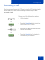
Using Timed Reminder Recall . . . . . . . . . . . . . . . . . . . . . . . 140
Using Attendant Recall . . . . . . . . . . . . . . . . . . . . . . . . . . . . . 141
Using Call Park . . . . . . . . . . . . . . . . . . . . . . . . . . . . . . . . . . . 141
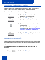
Recording a Calling Party Number . . . . . . . . . . . . . . . . . . . . 144
Displaying incoming calls . . . . . . . . . . . . . . . . . . . . . . . . . . . 144
Tracing a malicious call . . . . . . . . . . . . . . . . . . . . . . . . . . . . 145
Using Automatic Answerback . . . . . . . . . . . . . . . . . . . . . . . . 146
Using Call Pickup . . . . . . . . . . . . . . . . . . . . . . . . . . . . . . . . . 146
Using Call Waiting . . . . . . . . . . . . . . . . . . . . . . . . . . . . . . . . 148
Using Call Forward . . . . . . . . . . . . . . . . . . . . . . . . . . . . . . . . 150
Using Internal Call Forward . . . . . . . . . . . . . . . . . . . . . . . . . 151
Using Remote Call Forward . . . . . . . . . . . . . . . . . . . . . . . . . 152
Securing your IP Phone . . . . . . . . . . . . . . . . . . . . . . . . . . . . 154
Using the Call Join feature . . . . . . . . . . . . . . . . . . . . . . . . . . 156
7
Contents
Setting up a conference call . . . . . . . . . . . . . . . . . . . . . . . . . 156
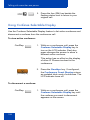
Using Conferee Selectable Display . . . . . . . . . . . . . . . . . . . 158
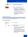
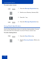
Using Group Call . . . . . . . . . . . . . . . . . . . . . . . . . . . . . . . . . 159
Using Make Set Busy . . . . . . . . . . . . . . . . . . . . . . . . . . . . . . 161
Call Deflect . . . . . . . . . . . . . . . . . . . . . . . . . . . . . . . . . . . . . . 161
Using AutoDial Transfer . . . . . . . . . . . . . . . . . . . . . . . . . . . . 163
Using the Buzz signal . . . . . . . . . . . . . . . . . . . . . . . . . . . . . . 164
Using Call Page Connect to make an announcement . . . . . 164
Using Centrex/Exchange Line Switchhook Flash . . . . . . . . . 165
Charging a call or charging a forced call . . . . . . . . . . . . . . . 165
Using Enhanced Override . . . . . . . . . . . . . . . . . . . . . . . . . . 168
Using Forced Camp-on feature . . . . . . . . . . . . . . . . . . . . . . 169
Overriding a busy signal . . . . . . . . . . . . . . . . . . . . . . . . . . . . 170
Using Privacy Release . . . . . . . . . . . . . . . . . . . . . . . . . . . . . 171
Using Radio Page . . . . . . . . . . . . . . . . . . . . . . . . . . . . . . . . . 172
Using Voice Call . . . . . . . . . . . . . . . . . . . . . . . . . . . . . . . . . . 174
Using the Personal Directory . . . . . . . . . . . . . . . . . . . . . . . . 175
Using the Callers List . . . . . . . . . . . . . . . . . . . . . . . . . . . . . . 178
Using the Redial List . . . . . . . . . . . . . . . . . . . . . . . . . . . . . . . 180
Using Virtual Office . . . . . . . . . . . . . . . . . . . . . . . . . . . . . . . . 182
Logging in to Virtual Office . . . . . . . . . . . . . . . . . . . . . . . 183
Using Virtual Office on your Remote IP Phone . . . . . . . 185
Using Virtual Office on your Office IP Phone . . . . . . . . . 187
Logging out of Virtual Office . . . . . . . . . . . . . . . . . . . . . . 189
Automatic log out from Virtual Office . . . . . . . . . . . . . . . 189
Emergency calls on your Remote IP Phone . . . . . . . . . 189
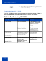
Troubleshooting Virtual Office . . . . . . . . . . . . . . . . . . . . 190
Using Media Gateway 1000B . . . . . . . . . . . . . . . . . . . . . . . . 192
Using Test Local Mode . . . . . . . . . . . . . . . . . . . . . . . . . 193
8
Contents
Using Resume Normal Mode . . . . . . . . . . . . . . . . . . . . . 193
Troubleshooting MG 1000B . . . . . . . . . . . . . . . . . . . . . . 194
Configuring Automatic Wake-Up . . . . . . . . . . . . . . . . . . . . . 195
Activating Message Registration . . . . . . . . . . . . . . . . . . . . . 197
Using Maid Identification . . . . . . . . . . . . . . . . . . . . . . . . . . . 198
Displaying Room Status . . . . . . . . . . . . . . . . . . . . . . . . . . . . 199
Using Record On Demand key . . . . . . . . . . . . . . . . . . . . . . . 202
Using SAVE key . . . . . . . . . . . . . . . . . . . . . . . . . . . . . . . 203
Other . . . . . . . . . . . . . . . . . . . . . . . . . . . . . . . . . . . . . . . . . . . 207
DenAn regulatory notice for Japan . . . . . . . . . . . . . . . . . . . . 208
Before you begin . . . . . . . . . . . . . . . . . . . . . . . . . . . . . . 210
Connecting the components of the IP Phone . . . . . . . . . 210
9
Contents
10
About the Nortel IP Phone 1165E
About the Nortel IP Phone 1165E
The IP Phone 1165E builds on the award-winning IP Phone 1100 Series
industrial design and offers a high resolution color display and new
graphical user interface elements that enhance the user experience. The
IP Phone 1165E provides easy access to multiple lines and call
processing features. It supports converged (voice and data) applications
through External Application Server APIs to provide productivity
enhancing applications and to enrich user experience with advanced
multimedia interaction. (See Note 1).
Experience the display capabilities by personalizing the background
image of the IP Phone 1165E display, and loading digital pictures into the
IP Phone to view a Digital Picture Slideshow when the IP Phone is idle.
The audio experience is enhanced through engineered audio tuning, and
supports wideband (see Note 2) with a newly-stylized handset that has
been softly contoured for additional comfort when using the handset.
Note 1: This feature requires an External Application Server.
Note 2: Wideband has dependencies on Nortel Communication
Platform support, including Communication Server 1000 and is
minimum-release dependent.
11
About the Nortel IP Phone 1165E
Basic features
Your IP Phone 1165E supports the following features:
•
up to sixteen line/feature keys with indicators using the Shift feature
•
four soft keys to provide easy access to features and call control
•
high resolution color display
•
high-quality handsfree speakerphone
•
wideband audio support for handset, headset, speaker, and
handsfree microphone
•
volume control keys for adjusting ringer, handsfree, handset, and
headset volume
•
seven specialized feature keys:
— Quit
— Directory
— Message/Inbox
— Shift/Outbox
— Services
— Copy
— Expand
•
five call-handling keys:
— Mute
— Handsfree
— Goodbye
— Headset
— Hold
•
two Gigabit Ethernet ports—for LAN and PC connections
•
integrated headset support for wired and wireless options including
USB and Bluetooth Wireless Technology
•
IEEE 802.3af PoE or local AC power options
12
About the Nortel IP Phone 1165E
•
hearing aid compatibility
•
USB port for connecting a USB keyboard, USB mouse, USB headset,
USB flash drive and powered hubs
•
USB access control (USB lock) that controls how the USB port on the
IP Phone 1165E can be used
•
support for Graphical External Application Server (GXAS) protocol
that enables External Application Server APIs to provide feature
functionality
•
support for the IP Phone 1100 Series Expansion Module to add keys
For information about using the Expansion Module, see the Expansion
Module for IP Phone 1100 Series User Guide (NN43130-101).
13
About the Nortel IP Phone 1165E
Telephone controls
Figure 1 on page 14 shows the IP Phone 1165E.
Figure 1: IP Phone 1165E
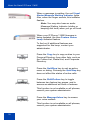
This section describes the controls on your IP Phone 1165E.
Context Sensitive Soft keys are located
below the display area. The LCD label above
each key changes, based on the active
feature. These keys are referred to as Soft
keys throughout this document.
14
About the Nortel IP Phone 1165E
When a triangle appears before a soft key
label, the feature is active.
Press the More... key to access the next
layer of soft keys.
The keys on either side of the LCD display
area are Self-labeled Line/Programmable
feature keys, with labels on the LCD. These
keys also function as line (DN) keys.
These keys are referred to as Line/ feature
keys throughout the remainder of this guide.
A steady LCD icon beside a line (DN) key
indicates that the line is active. A flashing
LCD icon indicates the line is on hold or the
feature is being programmed.
A steady LCD icon beside a feature key
indicates that the feature is active. A flashing
LCD icon indicates that the feature is being
programmed.
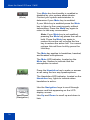
(Volume +)
(Volume -)
Use the Volume control buttons to adjust
the volume of the ringer, handset, headset,
speaker, and the Handsfree feature. Press
the top button to increase the volume, and
press the bottom button to decrease the
volume.
15
About the Nortel IP Phone 1165E
(Mute)
Your Mute key functionality is enabled or
disabled by your system administrator.
Contact your system administrator to
determine if your Mute key is enabled.
If your Mute key is enabled.press the Mute
key to listen to the receiving party without
transmitting. Press the Mute key again to
return to two-way conversation.
Note: If you Mute key is not enabled,
pressing the Mute key places the call on
hold. Press the Mute key again to
restore the active call or press the line
key to restore the active call. You cannot
retrieve this call from hold by press the
Hold key.
The Mute key applies to handsfree, handset,
and headset microphones.
The Mute LED indicator, located on the
Mute key, flashes to indicate that the
microphone is muted.
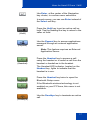
Press the Handsfree key to make or answer
a call using the two way speakerphone.
(Handsfree)
The Handsfree LED indicator, located on the
Handsfree key, lights to indicate when
handsfree is active.
Use the Navigation keys to scroll through
menus and lists appearing on the LCD
display screen.
(Navigation)
16
Use Up and Down to scroll up and down in
lists.
About the Nortel IP Phone 1165E
Use Enter, at the center of the Navigation
key cluster, to confirm menu selections.
In most menus, you can use Enter instead of
the Select soft key.
(Hold)
Press the Hold key to put an active call on
hold. Tap the flashing line key to return to the
caller on hold.
(Expand)
Use the Expand key to access applications
managed through an external application
server.
Note: This feature requires an External
Application Server.
(Headset)
Press the Headset key to answer a call
using the headset or to switch a call from the
handset or handsfree to the headset.
The Headset LED indicator, located on the
Headset key, lights to indicate that the
headset is in use.
(Headset)
(Headset)
(Goodbye)
Press the Headset key twice to open the
Bluetooth Setup menu.
If the Bluetooth wireless technology is not
enabled on your IP Phone, this menu is not
available.
Use the Goodbye key to terminate an active
call.
17
About the Nortel IP Phone 1165E
When a message is waiting, the red Visual
Alerter/Message Waiting indicator lights.
Also, when the ringer sounds, this indicator
flashes.
Note: You may also hear an audio
Message Waiting Indicator (stutter or
beeping dial tone) when you go off-hook.
When your IP Phone 1165E firmware is
being updated, the blue Feature Status
Lamp indicator flashes.
To find out if additional features are
supported for this lamp, contact your
administrator.
(Copy)
Press the Copy key to copy entries to your
Personal Directory from other lists, such as
the Callers List, Redial List, and Corporate
Directory.
(Quit)
Press the Quit/Stop key to exit an active
menu or dialog. Pressing the Quit/Stop key
does not affect the status of active calls.
(Shift/Outbox)
Press the Shift/Outbox key to toggle
between two feature key pages, and to
access an additional six lines or features.
This function is not available on all phones;
consult your system administrator.
(Msg/Inbox)
Press the Message/Inbox key to access
your voice mailbox.
This function is not available on all phones;
consult your system administrator.
18
About the Nortel IP Phone 1165E
(Directory)
(Services)
Press the Directory key to access directory
services.
Press the Services key, and then use the
navigation keys to access the following
items:
•
Telephone Options:
—
—
—
—
—
—
—
—
—
—
—
—
—
—
—
•
Volume adjustment...
Contrast adjustment
Language...
Date/Time
Display diagnostics
Local Dialpad Tone
Set Info
Diagnostics
Call Log Options
Ring type...
Call timer
On hook default path
Change FeatureKey label
Name Display Format
Live Dial Pad
Password Admin:
— Station Control Password
The Password Admin menu is not
available on all IP Phones. Consult your
system administrator.
•
Virtual Office Login and Virtual Office
Logout (if Virtual Office is configured)
— Press the Services key to exit from
any menu or menu item.
19
About the Nortel IP Phone 1165E
(Services)
Press the Services key twice to access the
Local Tools menu, and then use the Left /
Right navigation keys to access the following
items:
(Services)
•
Preferences
•
Diagnostics
•
Configuration
•
Locks
(Navigation Keys)
If you attempt to access the Local Tools
menu, and a dialog box appears prompting
you for a password, contact your system
administrator. Your system administrator can
establish a password for the Local Tools
menu.
Telephone display
The IP Phone 1165E provides a 4.1 inch (diagonal measured) color
QVGA TFT display, capable of displaying a QVGA 320 x 240 (width by
height) image. The graphics controller supports 24-bit color (16 million
colors).
Your IP Phone 1165E provides three display areas:
•
The upper display area provides labels for the eight line/ feature key
labels.
•
The middle display area contains information for items such as caller
number, caller name, Call Timer, feature prompt strings, user-entered
digits, date and time information, and IP Phone information.
•
The lower display area provides labels for the four soft keys.
Figure 2 on page 21 shows the IP Phone 1165E display area, including
the line/feature keys and soft keys.
20
About the Nortel IP Phone 1165E
Figure 2: IP Phone 1165E display area
Self-labeled line/programmable feature key labels appear beside the line
keys, and context-sensitive soft key labels appear directly above the soft
keys. Self-labeled means that the label next to the line/feature key is
presented from the call server automatically if a feature is programmed,
and can also be edited and changed by the user. Context-sensitive
means that the labels that appear above the soft keys present the
features that are available to the user at that time. The soft key labels
change depending on the active feature or the state of the call.
Self-labeled line/programmable feature keys are referred to as line/
feature keys and Context Sensitive Soft keys are referred to as soft keys
throughout this document.
21
About the Nortel IP Phone 1165E
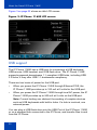
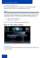
Figure 3 on page 22 shows an idle LCD screen.
Figure 3: IP Phone 1165E LCD screen
USB support
The IP Phone 1165E has a USB port for connecting a USB keyboard,
USB mouse, USB headset, and USB flash drive. The IP Phone 1165E
supports powered downstream 1.1-compliant USB hubs, including USB
2.0 hubs, if they offer USB 1.1-backwards compliancy.
There are two levels of power for the USB port.
•
When you power the IP Phone 1165E through Ethernet POE, the
IP Phone 1165E provides up to 100 mA at 5 volts for the USB port.
•
When you power the IP Phone 1165E through local AC power, the IP
Phone 1165E provides up to 500 mA at 5 volts on the USB port.
Note: Current limiting can obstruct the working of complex devices
such as USB keyboards with built-in hubs. If a hub is involved, use
external power.
You can plug a USB flash drive into the USB Port of the IP Phone 1165E
or on a powered hub connected to the IP Phone, and transfer files to and
from the IP Phone.
22
About the Nortel IP Phone 1165E
License Notification
Notify your system administrator if your IP Phone displays a message in a
pop-up window about the licensing feature or evaluation period. License
notification provides details to help diagnose why the features are
disabled on the IP Phone. You can press the Stop key or lift the handset
to close the window. The window redisplays every 24 hours at 1:00 AM
(default). The time and time frame can be configured when you provision
the IP Phone. For information about provisioning the IP Phones, see
Nortel Communication Server 1000 IP Phones Fundamentals (NN43001368).
Call features and Flexible Feature Codes
Some features are not available on all IP Phones. Call features and
Flexible Feature Codes (FFC) must be assigned to your IP Phone 1165E,
and supported by system software. Contact your system administrator to
configure these features and codes on your IP Phone 1165E.
Security features
The following security features are available on your IP Phone 1165E:
•
Encrypted calling
•
Station Control Password (SCPW)
Encrypted calling
Your IP Phone 1165E supports secure communication using SRTP
media encryption. If the feature is enabled, a security icon (q) appears on
the screen when your call is secured using SRTP media encryption.
Contact your system administrator to find out if this feature is available for
your use.
23
About the Nortel IP Phone 1165E
Station Control Password (SCPW)
Your Station Control Password (SCPW) enables the following security
features:
•
Electronic Lock to prevent others from making calls from your IP
Phone
•
password-protected IP Phone features (for example, Personal
Directory, Redial List, and Callers List)
Your system administrator defines your initial SCPW. Contact your
system administrator for detailed information.
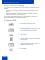
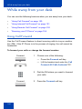
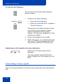
To change your SCPW:
1. Press the Services key once.
(Services)
2. Press the Up/Down keys to scroll, and
then highlight Password Admin.
3. Press Enter.
4. Use the dialpad to enter your password
at the prompt.
5. Press the Up/Down keys to scroll and
highlight New Password.
6. Press Enter.
24
About the Nortel IP Phone 1165E
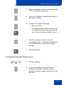
7. Use the dialpad to enter the new
password.
Select
8. Press the Select soft key to accept the
new password.
If you are locked out of your
IP Phone 1165E, or if you forget your
SCPW, contact your system
administrator.
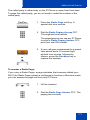
Note: The default configuration for Password Protection is off.
To turn Password Protection on or off:
1. Press the Directory key.
(Directory)
2. Press the Up/Down navigation keys to
scroll and highlight Change Protection
Mode.
3. Use the dialpad to enter your password
(if Password Protection is enabled).
Enter
4. Press the Enter key.
25
About the Nortel IP Phone 1165E
5. Press the Up/Down navigation keys to
scroll and highlight one of the following:
— Enable Password Protection
— Disable Password Protection
6. Choose one of the following soft keys:
Yes
No
or
Done
26
— Yes to accept the selection
— No to return to the Directory menu
7. Press the Done soft key.
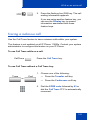
Entering and editing text
Entering and editing text
You can enter and edit text on your IP Phone 1165E using the following
methods:
•
“Entering text using the IP Phone dialpad” on page 27
•
“Entering text using the USB keyboard” on page 28
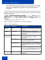
The use of any of these methods for text entry or editing depends on the
application. Table 1 shows the applications and input devices that you
can use for text entry.
Table 1: Application text entry
For:
Use:
Call Server-related applications
(for example, changing feature
key labels, adding personal
directory entries, or dialing)
Dialpad
Graphical applications
USB keyboard
Local Tools menu
USB keyboard
USB keyboard for numeric
entries only
Dialpad for numeric entries
Entering text using the IP Phone dialpad
You can use the dialpad to enter text when you use features such as
Personal Directory, Redial List, and Callers List. Use the dialpad in
conjunction with the soft keys.
For example, if you want to enter the letter A, press the number 2 key
once. If you want to enter the letter C, press the number 2 key three
times. No letters are associated with the number 1 or the 0 keys;
however, punctuation is associated with these keys.
27
Entering and editing text
Entering text using the USB keyboard
You can use the USB keyboard, when connected, to enter text in the tools
and graphical applications.
For number entry in IP Phone applications (for example, when dialing),
you can use the keyboard to enter digits (0 to 9), as well as * and #. Other
characters are ignored.
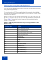
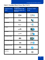
When on a call, you can use the function keys (f1, f2, f3, f4, f5, f6, f7, f8,
f9, f10, f11, f12, f13, f14, f15, f16, f17, f18, f19, and f20) to control the IP
Phone. Table 2 shows the function keys and their associated action
during IP Phone calls.
Table 2: USB keyboard function keys during IP Phone calls
(Part 1 of 2)
Function key
Action
f1
Go to Handsfree mode
f2
Go to Headset mode
f3
Place the current call on hold
f4
Mute the current call
f5
Volume up
f6
Volume down
f7
Copy
f8
Quit
f9
Services (Globe)
f10
Expand to PC
f11
DN/Feature key 0
f12
DN/Feature key 1
f13
DN/Feature key 2
28
Entering and editing text
Table 2: USB keyboard function keys during IP Phone calls
(Part 2 of 2)
Function key
Action
f14
DN/Feature key 3
f15
DN/Feature key 4
f16
DN/Feature key 5
f17
Soft key 1
f18
Soft key 2
f19
Soft key 3
f20
Soft key 4
0–9
0–9
A–Z
A–Z
a–z
a–z
Note: Contact your system administrator to see if USB keyboard
function keys are supported on your IP Phone 1165E.
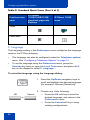
Editing text using the soft keys
You can use the softkeys, in conjunction with the dialpad, to easily edit
text when you use features such as Personal Directory, Redial List, and
Caller List.
To edit an entry in your Personal Directory, press the Directory key, and
select the desired entry from your Personal Directory.
To edit text with the soft keys:
1. Press the Edit soft key.
2. Press the Left/Right navigation keys to move through the text.
3. Select the appropriate editing soft key for the operation you want to
perform.
29
Entering and editing text
4. If the character you want is not visible, press the More... soft key to
access the next layer of soft keys.
5. To add non-alphanumeric symbols, press the Symbol soft key, and
perform one of the following:.
a. Press the Left/Right navigation keys to move to a specific
symbol and press the Choose soft key to select a symbol.
b. Press the Next soft key to exit without editing the text.
When you are editing text using the soft keys, various commands are
available on the softkeys to help you, as described in Table 3 on
page 30.
Table 3: Editing text using soft keys
Soft key
Description
Cancel
Cancel an action.
Choose
Select a non-alphanumeric symbol (available
only after the Symbol soft key is selected).
Clear
Clear the input field.
Case
Switch the next character to either uppercase or
lowercase.
Delete
Backspace one character.
Done/Select/Enter
Varies, depending on the state of your IP Phone.
More...
Access additional soft keys.
30
Virtual Private Network
Virtual Private Network
A Virtual Private Network (VPN) is a network that uses a public network
infrastructure, such as the Internet, to provide you with secure access to
the private network of your organization.
The IP Phone VPN feature allows you to connect to your organization’s
private network from a public or remote network. For example, you can
use your home public Internet connection to connect to your
organization’s private network.
This chapter describes the procedure to upgrade the software of your IP
Phone (if required) and configure the VPN on your IP Phone. An
installation wizard helps you perform the necessary steps.
Note: The Nortel Phone VPN Configuration Wizard uses the default
language of the operating system of your PC. If the language is not
supported by the wizard, the default wizard language is English.
Your system administrator provides you with all the necessary files you
require to configure your IP Phone for VPN, and helps you to resolve any
errors that occur during configuration.
Before you begin
Before you upgrade the IP Phone software and configure VPN on your IP
Phone, complete the following checklist.
•
Ensure that your PC is using one of the following operating systems:
— Windows XP
— Windows Vista
— Macintosh OS
•
Ensure that you received a copy of the provisioning files from your
network administrator. The following files should be included:
— Nortel Phone VPN Configuration Wizard.jar
— provisioning files (for example: system.prv)
31
Virtual Private Network
— .bin files (for example: 0625C7C.bin)
•
Java Virtual Machine (JVM) version 1.2 or later must be installed on
your PC. To check click Start-> Settings-> Control Panel-> Java to see if
JVM is installed on your machine and the version of it. If it is not
installed, contact your system administration to help you to install it.
To download the latest JVM, go to www.java.com.
•
Ensure that your PC has a firewall that allows incoming
communication to the following ports:
— UDP Port 69 (TFTP)
— TCP Port 80 (HTTP)
— UDP Port 49000
Note: The Nortel Phone VPN Configuration Wizard.jar file creates a
log.txt file during execution. This file is helpful to troubleshoot
problems you experience using the Nortel Phone VPN Configuration
Wizard.jar. The log.txt file is located in the same directory as
Nortel Phone VPN Configuration Wizard.jar.
Connecting your IP Phone
Before you connect your IP Phone to your PC, ensure that components of
your IP Phone are connected properly.
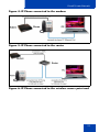
Connect your IP Phone using one of the following methods:
•
connect to your modem. See Figure 4 on page 33.
•
connect to your router. See Figure 5 on page 33.
•
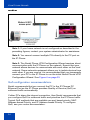
connect to your wireless access point and modem. See Figure 6 on
page 33.
32
Virtual Private Network
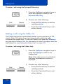
Figure 4: IP Phone connected to the modem
Figure 5: IP Phone connected to the router
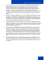
Figure 6: IP Phone connected to the wireless access point and
33
Virtual Private Network
modem
Note 1: If your home network is not configured as described in the
preceding figures, contact your system administrator for assistance.
Note 2: You cannot connect multiple PCs directly to the PC port on
the IP Phone.
Note 3: The Nortel Phone VPN Configuration Wizard requires direct
communication with the IP Phone on the network. Ensure that your
network allows devices to communicate with each other on the local
network. Some network equipment allows you to isolate devices from
each other. If you are unsure, it is recommended that you temporarily
connect your PC to the IP Phone to run the initial Nortel Phone VPN
Configuration Wizard. See Figure 4 on page 33.
QoS configuration recommendations
Nortel recommends that you connect the PC to the IP Phones PC
Ethernet Port as the IP Phone provides Quality of Service (QoS) on
outbound traffic automatically.
If other PCs share the internet connection, then Nortel recommends that
you configure QoS for outbound traffic and prioritize the IP Phone traffic.
Typical QoS methods that are available are port based priority, MAC
Address based Priority, and IP Address based Priority. To configure
QoS, see your router documentation.
34
Virtual Private Network
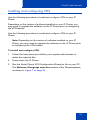
Installing and configuring VPN
Use the following procedure to install and configure VPN on your IP
Phone.
Depending on the version of software installed on your IP Phone, you
may need to upgrade the software on the IP Phone prior to configuring
the VPN feature.
Use the following procedure to install and configure VPN on your IP
Phone.
Note: Depending on the version of software installed on your IP
Phone, you may need to upgrade the software on the IP Phone prior
to configuring the VPN feature.
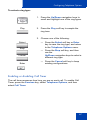
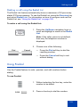
To install and configure VPN
1. Follow the instructions provided by your system administrator to
obtain the required files.
2. Power-down the IP Phone.
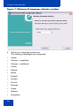
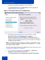
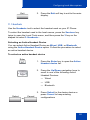
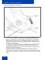
3. Run the Nortel Phone VPN Configuration Wizard.jar file on your PC.
The Welcome & language selection window of the Wizard appears,
as shown in Figure 7 on page 36.
35
Virtual Private Network
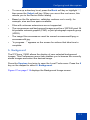
Figure 7: Welcome & language selection window
4. Select your language preference.
The following languages are supported:
•
Arabic
•
Chinese - simplified
•
Chinese - traditional
•
Czech
•
Danish
•
Dutch
•
English
•
Finnish
•
French
•
German
•
Greek
•
Hebrew
•
Hungarian
36
Virtual Private Network
•
Italian
•
Japanese - Katakana
•
Japanese - Kanji
•
Korean
•
Latvian
•
Norwegian
•
Polish
•
Portuguese
•
Russian
•
Spanish
•
Swedish
•
Turkish
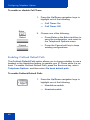
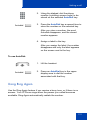
5. Click Next.
The Equipment Setup and VPN window appears, as shown in
Figure 8 on page 38.
37
Virtual Private Network
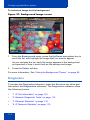
Figure 8: Equipment Setup and VPN window
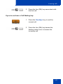
6. Verify that the modem, IP Phone, and PC are connected properly.
7. Disconnect any VPN connection currently running on your PC.
Confirm that your LAN Ethernet Port and PC Ethernet Port on the IP
Phone are connected correctly.
Note: Connect the IP Phone LAN Ethernet port, marked with the %
symbol on the back of the IP Phone to your network equipment only.
Connect only one PC (if applicable) to the PC Ethernet port, marked
with the ( symbol on the back of the IP Phone.
Note: Optional: Click More to read a description of VPN.
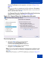
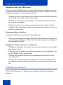
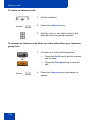
8. Click Next.
The Locate Data Files window appears, as shown in Figure 9 on
page 39.
38
Virtual Private Network
Figure 9: Locate Data Files
9. Click Browse to locate the provisioning files provided by your system
administrator, if the wizard was not able to locate the files.
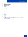
10. Click Next.
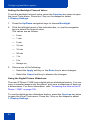
The Prepare Phone for Configuration window appears as shown in
Figure 10 on page 40.
39
Virtual Private Network
Figure 10: Prepare Phone for Configuration
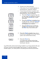
11. Power on your IP Phone.
Note: Depending on the current software version on the IP Phone,
“Listening Mode” may not be detected. If your IP Phone does not
enter “Listening Mode”, follow the steps below.
12. After you hear the chimes tune and the text NORTEL appears on the
IP Phone display screen, quickly press the following keys in order.
13. Verify that the IP Phone displays Listening Mode.
a. The IP Phone can take up to 60 seconds for “Listening Mode” to
appear in the display area.
If the IP Phone displays Listening Mode, click Yes and go to
Step 15.
OR
If the IP Phone does not display Listening Mode, click No.
40
Virtual Private Network
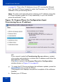
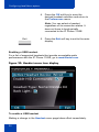
The Prepare Phone for Configuration (Try again) window
appears.
Figure 11: The Prepare Phone for Configuration (Try again)
a. Power off your IP Phone and power it back on again.
14. After you hear the chimes tune and the text NORTEL appears on the
IP Phone display screen, quickly press the following keys in order.
Note: The IP Phone can take up to 60 seconds for “Listening Mode”
to appear in the display area.
b. If the IP Phone displays Listening Mode, click Yes and go to
Step 15.
OR
If the IP Phone does not display Listening Mode, then your IP
Phone requires a software upgrade in order to proceed.
Click No to proceed to a software upgrade. Follow the next steps
41
Virtual Private Network
to perform a software upgrade on your IP Phone.
The Prepare Phone for Configuration window appears as
shown in Figure 12 on page 42.
Figure 12: Prepare Phone for Configuration
c.
Double-press the Services key on the IP Phone quickly.
Select the Network Configuration menu item.
Move the cursor to locate Provision: or (TFTP IP:) in the
Network Configuration menu, and then write down the existing
address of the provisioning server so you can refer to it after you
complete this procedure.
Note: If a password prompt dialog box appears, press Cancel. Wait
until your IP Phone display completes the “Starting DHCP…” screen,
then perform Step c again.
For information about entering and editing text in the Local menu, see
“Entering and editing text” on page 27.
d. If you are able to navigate to the Provision: or (TFTP IP:)
parameter, and edit this field, click Yes.
The Prepare Phone for Configuration (Input Provisioning
42
Virtual Private Network
Server IP address) window appears, as shown in Figure 14 on
page 44.
OR
If you are not able to navigate and edit the address in Provision:
or (TFTP IP:) in the Network Configuration menu, or you were not
able to edit this field, click No.
The Prepare Phone for Configuration (Alternate Provisioning
Server) window appears. See Figure 13 on page 43.
Figure 13: Prepare Phone for Configuration (Alternate
Provisioning Server)
e. Press the Auto soft key on the IP Phone.
Navigate to 12. Provisioning Server.
Clear the Provisioning Server check box.
f.
Press the Config soft key on the IP Phone.
Navigate to the Provision: item.
Note: If you can locate the existing provisioning server address, write
it down so you can refer to it after you complete this procedure, then
click Yes.
Observe the Provision: or (TFTP IP) address, as shown in Figure 14
43
Virtual Private Network
on page 44. This is the IP Address of your PC running the Wizard
tool. Use the IP Phone keypad to enter the Provision: or (TFTP IP)
address of the provisioning server.
Note: To enter a dot (period) when entering an IP address using the
IP Phone keypad, press the 1 key repeatedly, or you can doublepress the asterisk (*) key.
Figure 14: Prepare Phone for Configuration (Input
Provisioning Server IP address)
OR
If you cannot locate the Provisioning Server address, contact
your system administrator to obtain the IP address and follow the
administrator instructions.
Click No to return to the Prepare Phone for Configuration
window shown in Figure 12 on page 42.
g.
To reset the IP Phone and begin the software update, press the
Apply&Reset key on the IP Phone.
The progress bar displays the percent complete of the software
transfer.
h. Restart your IP Phone.
44
Virtual Private Network
i.
Click Next.
j.
Go back to Step 12 and repeat the steps.
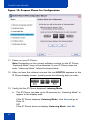
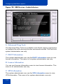
15. When the Autodiscover Phone window appears, as shown in
Figure 15 on page 46, click Autodiscover Phone to discover
connected IP Phones.
Note: Click Stop to stop the search.
The text “Searching for connected phones” displays while the
connected IP Phones are located. The text “Autodiscovery complete”
displays in the Nortel Phone VPN Configuration Wizard tool when the
search is finished.
If the search is successful, “Listening Mode: Connected” appears in
the IP Phone display area.
If the search is not successful, do the following
•
Ensure that the IP Phone continues to display “Listening
Mode: Listening…” during the Autodiscovery process. If
your IP Phone does not display this message, power down
the IP Phone and repeat the steps, starting with Step 11.
•
Ensure that UDP Port 49000 is not currently blocked by
your PC firewall.
•
Ensure that UDP Port 49000 is not already in use by
existing applications on your PC.
•
Review the log.txt file for additional information.
45
Virtual Private Network
Figure 15: Autodiscover Phone window
16. Click Next.
If more than one connected IP Phone was discovered, the
Autodiscover Phone (More than one phone was discovered)
window appears. See Figure 16 on page 47.
46
Virtual Private Network
Figure 16: Autodiscover Phone (More than one phone was
discovered)
a. Obtain the MAC address of the IP Phone for which you are
configuring the VPN. The MAC address is printed on a label
located on the back of the IP Phone.
b. Select the IP Phone to configure from the drop-down list.
c.
Click Next.
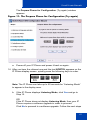
17. When the Configure phone window appears, as shown in Figure 17
on page 48, click Configure phone to initiate the provisioning
session that configures the VPN feature on the IP Phone.
47
Virtual Private Network
Figure 17: Configure Phone Window
The progress bar displays the percent complete of the provisioning file
transfer.
Configuring phone is displayed during the file transfer.
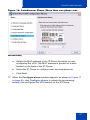
18. When Phone configuration complete is displayed, click Next.
The Confirmation & Finish window appears. See Figure 18 on page
49.
48
Virtual Private Network
Figure 18: Confirmation & Finish
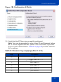
19. Verify that the IP Phone is successfully configured.
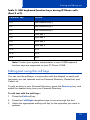
Note: You may be prompted to enter a User ID and Password before
the IP Phone registers with the system. This information is provided
by your system administrator. Table 4 on page 49 provides character
key mappings.
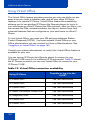
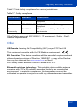
Table 4: Character key mappings (Part 1 of 2)
Key
Generates
0
0
1
_-.!@$%&+& ^\1
2
abcABC2
3
defDEF3
4
ghiGHI4
5
jklJKL5
49
Virtual Private Network
Table 4: Character key mappings (Part 2 of 2)
Key
Generates
6
mnoMNO6
7
pqrsPQRS7
8
RUVTUV8
9
wxyzWXYZ 9
*
., - + = ^ ; : ‘ \ “ *
#
{}|()<>[]#
a. Look for the following information on the IP Phone display:
— Date
— Time
— Type of call server
— Directory number
b. Lift the IP Phone handset and listen for a dial tone.
If the IP Phone is not configured successfully, ensure that the basic
requirements are met; repeat the steps in the Nortel Phone VPN
Configuration Wizard or contact your system administrator. For more
information about basic requirements, see “Before you begin” on
page 31.
50
Configuring Telephone Options
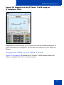
Configuring Telephone Options
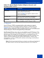
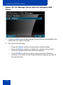
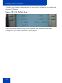
Your IP Phone 1165E Services menu lists the following submenus:
•
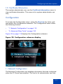
The Telephone Options menu enables you or your system
administrator to configure IP Phone preferences. The Telephone
Options menu offers the options shown in Figure 19 on page 51.
•
The Password Admin menu enables you or your system
administrator to change the Station Control Password (SCPW).
•
The Virtual Office Login and Test Local Mode (for branch office)
menus are listed when an IP Phone 1165E Class of Service is
configured for Virtual Office and branch office. (For more information,
see “Using Virtual Office” on page 182).
Note: The Password Admin, Virtual Office Login, and Test Local
Mode menus are not available on all systems. Consult your system
administrator to see if these features are available.
Figure 19: Telephone Options menu
Volume adjustment...
Call Log Options
Contrast adjustment
Ring type...
Language...
Call timer
Date/Time
On hook default path
Display diagnostics
Change Feature Key label
Local Dialpad Tone
Name Display Format
Set Info
Live Dial Pad
Diagnostics
51
Configuring Telephone Options
Using the Telephone Options menu
Use the Telephone Options menu to access the following:
•
“Adjusting the volume” on page 53
•
“Adjusting the display screen contrast” on page 54
•
“Selecting a language” on page 55
•
“Selecting date and time format” on page 56
•
“Accessing display diagnostics” on page 57
•
“Choosing a local dialpad tone” on page 57
•
“Viewing IP Phone information” on page 58
•
“Diagnostics” on page 59
•
“Configuring Call Log Options” on page 60
•
“Choosing a ring type” on page 66
•
“Enabling or disabling Call Timer” on page 67
•
“Enabling OnHook Default Path” on page 68
•
“Changing feature key labels” on page 69
•
“Configuring the name display format” on page 71
•
“Configuring Live Dial Pad” on page 72
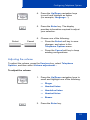
To use the Telephone Options menu:
1. Press the Services key.
(Services)
2. Press the Up/Down navigation keys to
scroll and highlight Telephone Options.
3. Press the Enter key.
52
Configuring Telephone Options
4. Press the Up/Down navigation keys
to scroll and highlight an option
(for example, Language…).
5. Press the Enter key. The display
provides information required to adjust
your selection.
6. Choose one of the following:
Select
Cancel
or
— Press the Select soft key to save
changes, and return to the
Telephone Options menu.
— Press the Cancel soft key to keep
existing configurations.
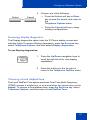
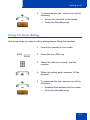
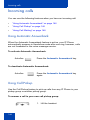
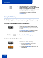
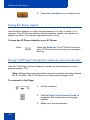
Adjusting the volume
To adjust the volume, press the Services key, select Telephone
Options, and then select Volume adjustment…
To adjust the volume:
1. Press the Up/Down navigation keys to
scroll and highlight one of the following:
— Ringer
— Handset listen
— Handsfree listen
— Headset listen
— Buzzer
2. Press the Enter key.
53
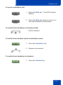
Configuring Telephone Options
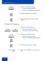
3. To increase the volume, press one of the
following three keys:
Up
— Up soft key
or
—
the Up navigation key
—
the Right navigation key
4. To decrease the volume, press one of
the following three keys:
Down
— Down soft key
— the Down navigation key
— the Left navigation key
5. Choose one of the following:
Select
Cancel
or
— Press the Select soft key or the
Enter key to save the volume level,
and return to the Telephone
Options menu.
— Press the Cancel soft key to keep
existing configurations.
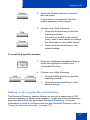
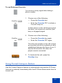
Adjusting the display screen contrast
To adjust the LCD screen contrast, press the Services key, select
Telephone Options, and then select Contrast adjustment.
You can also adjust the contrast using the Local Tools menu; Nortel
recommends that you use the control in the Telephone Options menu.
Note: If you have an Expansion Module for IP Phone 1100 Series
attached to your IP Phone, adjusting the IP Phone LCD screen
contrast also adjusts the display screen contrast for the Expansion
Module.
54
Configuring Telephone Options
To adjust the display screen contrast:
1. To increase the display contrast level,
press one of the following three keys:
Up
— Up soft key
— Up navigation key
— the Right navigation key
2. To decrease the display contrast level,
press one of the following three keys:
Down
— Down soft key
— the Down navigation key
— the Left navigation key
3. Choose one of the following:
Select
Cancel
or
— Press the Select soft key or the
Enter key to save the
changes, and return to the
Telephone Options menu.
— Press the Cancel soft key to keep
existing configurations.
Selecting a language
The display is available in multiple languages. To choose a language,
press the Services key, select Telephone Options, and then select
Language…
If the language setting is password-protected, you must enter a password
(SCPW) to change the language. If you enter an incorrect password, an
error message is displayed. If you enter an incorrect password more than
three times, the password functionality is locked. Contact your system
administrator to unlock the password.
55
Configuring Telephone Options
To select a language:
1. Press the Up/Down navigation keys to
scroll, and highlight the desired
language (for example, German
[Deutsche]).
Note: Some languages may not be
installed on your IP Phone. Contact your
system adminstrator for more
information about available languages.
2. Choose one of the following:
Select
Cancel
or
Enter
— Press the Select soft key or Enter
key to save the desired language,
and return to the Telephone
Options menu.
— Press the Cancel soft key to keep
existing configurations.
Selecting date and time format
Several date and time formats are available. Formats are based on the
12-hour and 24-hour clocks. To select the date and time format, press the
Services key, select Telephone Options, and then select Date/Time.
To select a date and time format:
1. Press the Up/Down navigation keys to
scroll and highlight the desired format.
Sample formats appear on the upperright side of the display area.
56
Configuring Telephone Options
2. Choose one of the following:
Select
— Press the Select soft key or Enter
key to save the format, and return to
the
Telephone Options menu.
Cancel
or
— Press the Cancel soft key to keep
existing configurations.
Accessing display diagnostics
The Display diagnostics option tests the IP Phone display screen and
indicator lights.To access Display diagnostics, press the Services key,
select Telephone Options, and then select Display diagnostics.
To use Display diagnostics:
1. Press the Up/Down navigation keys to
scroll through the list to view display
capabilities.
2. Press the soft key to the far right to
return to the Telephone Options menu.
Choosing a local dialpad tone
The Local DialPad Tone option produces Dual-Tone Multi-Frequency
(DTMF) sounds, a single tone, or no sound when you press a key on the
dialpad. To choose a local dialpad tone, press the Services key, select
Telephone Options, and then select Local DialPad Tone.
57
Configuring Telephone Options
To choose a local dialpad tone:
1. Press the Up/Down navigation keys to
scroll and highlight one of the following
dialpad tones:
— None to disable all tones
— Short Click to enable a single tone
for all keys
— DTMF to turn on a separate DTMF
tone for each key
2. Choose one of the following:
Select
Cancel
or
Enter
— Press the Select soft key or Enter
key to save the tone selection, and
return to the Telephone Options
menu.
— Press the Cancel soft key to keep
existing configurations.
Viewing IP Phone information
The Set Info option displays the following IP Phone-specific information:
•
General Info
•
Set IP Info
•
Ethernet Info
•
Server Info
•
Location Info
•
Encryption Info
To view IP Phone information, press the Services key, select Telephone
Options, and then select Set Info.
58
Configuring Telephone Options
To view IP Phone information:
1. Press the Up/Down navigation keys to
scroll through the list to view IP Phone
information.
Select
2.
Press the Select soft key or Enter key
to view the highlighted information
Enter
3. Press the Up/Down navigation keys to
scroll through the information.
Cancel
4. Press the Cancel soft key to return to
the previous menu.
Diagnostics
The Diagnostics option displays the following IP Phone-specific
information:
•
Diag Tools
•
EtherStats
•
IP Stats
•
RUDP Stats
•
QOS Stats
This menu is for administrator use only.
59
Configuring Telephone Options
Configuring Call Log Options
The Call Log Options screen displays the following items:
•
Incoming Calls
•
Preferred Name Match
•
Area Code Setup
Under Incoming Calls, the following can be selected:
•
Log Mode
•
New Call Indication
Use the Call Log Options screen to configure the following preferences:
•
“Configure the Incoming Calls – Log Mode” on page 60
•
“Configure the Incoming Call – New Call Indication” on page 62
•
“Configure Preferred Name Match” on page 63
•
“Configure Area Code Setup” on page 64
Configure the Incoming Calls – Log Mode
You can configure the Callers List to log all incoming calls including calls
while your phone is busy, or only unanswered calls. The default
configuration is Log All Calls.
To log only unanswered calls, press the Services key, select Telephone
Options, and then select Call Log Options from the menu.
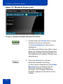
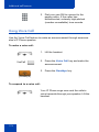
To select a log mode:
1. Highlight the Incoming Calls option and
press the Select soft key or Enter key.
2. Press the Up/Down navigation keys to
scroll and highlight the Log Mode
option.
60
Configuring Telephone Options
Select
3. Press the Select soft key or Enter key.
or
Enter
4. Press the Up/Down navigation keys to
highlight Log Unanswered Calls or Log
All Incoming Calls.
5. Choose one of the following:
Select
Cancel
or
Enter
— Press the Select soft key or Enter
key to save the configuration.
— Press the Cancel soft key to keep
existing configurations.
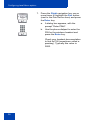
To log all incoming calls including calls while your IP Phone is busy, press
the Services key and select the Call Log Options from the Telephone
Options menu.
To log all incoming calls including calls while IP Phone is busy
6. Press the Up/Down navigation keys to
scroll and highlight the Incoming Calls
option.
Select
7. Press the Select soft key or Enter key.
61
Configuring Telephone Options
8. Press the Up/Down navigation keys to
scroll and highlight Log Calls if busy.
9. Choose one of the following:
Select
Cancel
or
— Press the Select soft key to save the
configuration.
— Press the Cancel soft key to keep
existing configurations.
Configure the Incoming Call – New Call Indication
You can configure your IP Phone 1165E to display a message to indicate
that a new incoming call was received. The default configuration is On. To
configure new call indication, press the Services key, select Telephone
Options, and then select Call Log Options.
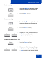
To configure New Call Indication:
1. Highlight the Incoming Calls option and
press the Select soft key or Enter key.
Select
or
Enter
2. Press the Up/Down navigation keys to
scroll and highlight New Call Indication.
62
Configuring Telephone Options
Select
3. Press the Select soft key or Enter key.
or
Enter
4. Press the Up/Down navigation keys to
scroll and highlight one of the following:
— New call indication off
— New call indication on
5. Choose one of the following:
Select
Cancel
or
Enter
— Press the Select soft key or Enter
key to save the configuration.
— Press the Cancel soft key to keep
existing configurations.
Configure Preferred Name Match
You can configure your IP Phone 1165E to display the name of the caller
as defined in your Personal Directory. The default configuration is Off. To
configure Preferred Name Match, press the Services key, select
Telephone Options, and then select Call Log Options.
To configure Preferred Name Match:
1. Press the Up/Down navigation keys to
scroll and highlight Preferred Name
Match.
2. Press the Select soft key.
63
Configuring Telephone Options
3. Press the Up/Down navigation keys to
scroll and highlight one of the following:
— Preferred name match on
— Preferred name match off
Select
4. Choose one of the following:
Enter
— Press the Select soft key or Enter
key to save the configuration.
Cancel
— Press the Cancel soft key to keep
existing configurations.
Configure Area Code Setup
Use the Area Code Setup menu to save up to three area codes. When
an incoming call arrives with an area code that matches one of the three
stored area codes, the incoming call number is reordered to display the
telephone number followed by the area code (as opposed to the area
code followed by the telephone number). This reordering is also
performed when you scroll through your Callers List.
To configure area codes, press the Services key, select Telephone
Options, and then select Call Log Options.
To configure default area codes (maximum of three):
1. Press the Up/Down navigation keys to
scroll and highlight Area Code Setup.
Select
64
2. Press the Select soft key.
Configuring Telephone Options
3. Press the Up/Down navigation keys to
scroll and highlight one of the following:
— Area Code # 1
— Area Code # 2
— Area Code # 3
Select
4. Press the Select soft key.
5. Use the dialpad to enter the area code at
the prompt.
Select
Enter
Cancel
6. Choose one of the following:
— Press Enter or the Select soft key to
save the configuration.
— Press the Cancel soft key to keep
the existing configurations.
Note: Refer to Table 3 on page 30 for
an explanation of other available soft
keys.
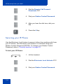
To edit area code display:
1. Press the Up/Down navigation keys to
scroll and highlight Area Code Setup.
65
Configuring Telephone Options
2. Press the Select soft key.
Select
3. Press the Up/Down navigation keys to
scroll and highlight one of the following:
— Area Code # 1
— Area Code # 2
— Area Code # 3
4. Press the Select soft key.
Select
5. Use the dialpad to edit the number.
Enter
6. Choose one of the following:
— Press the Select soft key or Enter
key to save the configuration.
Select
Cancel
or
— Press the Cancel soft key to keep
existing configurations.
Note: Refer to Table 3 on page 30 for
the explanation of other available soft
keys.
Choosing a ring type
The Ring type… option configures the IP Phone ring tone. To choose a
ring type, press the Services key, select Telephone Options, and then
select Ring type…
66
Configuring Telephone Options
To select a ring type:
1. Press the Up/Down navigation keys to
scroll and highlight one of the ring types.
Play
2. Press the Play soft key to sample the
ring tone.
3. Choose one of the following:
Select
Stop
Cancel
Enter
— Press the Select soft key or Enter
key to save the ring type, and return
to the Telephone Options menu.
— Press the Stop soft key, and then
use the
Up/Down navigation keys to select a
different ring type.
— Press the Cancel soft key to keep
existing configurations.
Enabling or disabling Call Timer
The call timer measures how long you are on each call. To enable Call
Timer, press the Services key, select Telephone Options, and then
select Call Timer.
67
Configuring Telephone Options
To enable or disable Call Timer:
1. Press the Up/Down navigation keys to
highlight one of the following:
— Call Timer: On
— Call Timer: Off
Enter
2. Choose one of the following:
Select
— Press Enter or the Select soft key to
save the configuration, and return to
the Telephone Options menu.
Cancel
— Press the Cancel soft key to keep
existing configurations.
Enabling OnHook Default Path
The OnHook Default Path option allows you to choose whether to use a
headset or the Handsfree feature to operate your IP Phone while it is onhook. To enable OnHook Default Path, press the Services key, select
Telephone Options, and then select On hook default path.
To enable OnHook Default Path:
1. Press the Up/Down navigation keys to
highlight one of the following:
— Handsfree enable
— Headset enable
68
Configuring Telephone Options
Enter
Select
2. Choose one of the following:
— Press the Select soft key or Enter
key to save the default path, and
return to the Telephone Options
menu.
Cancel
or
— Press the Cancel soft key to keep
existing configurations.
Changing feature key labels
The Change FeatureKey label option renames the label displayed next
to each feature key or restores the default labels to the keys (collectively
or individually). To rename feature key labels, press the Services key,
select Telephone Options, and then select Change FeatureKey label.
If the feature key label setting is password-protected, you must enter a
password (SCPW) to change the feature key label. If you enter an
incorrect password, an error message is displayed. If you enter an
incorrect password more than three times, the password functionality is
locked. Contact your system administrator to unlock the password.
Note: If a feature key is configured as an auto-dial key, the label does
not change if the auto-dial key configuration changes.
To rename the labels:
1. Select the Change FeatureKey label
option.
Enter
2.
Press Enter or the Select softkey.
Select
69
Configuring Telephone Options
3. Press the feature key that you are
changing.
2493
If you press a prime DN key, an error
message appears.
The error message that appears is
Enter
Can't chg PrimeDN key
In order to return from the menu from
this error message you need to press the
OK soft key or the Enter key.
Ok
4. Enter the new information for the feature
key label. To enter special characters,
press the Up navigation key. For
information about entering text, see
“Entering text using the IP Phone
dialpad” on page 27.
5. Choose one of the following:
Select
Cancel
or
— Press the Select soft key to save the
changes, and return to the
Telephone Options menu.
— Press the Cancel soft key to keep
existing configurations.
70
Configuring Telephone Options
To restore the default labels:
To restore feature key labels, press the Services key, select Telephone
Options, and then select Change FeatureKey label.
1. Use the Up/Down navigation keys to
scroll and highlight one of the following:
a. Restore all key labels
— Press the Select soft key or Enter
key.
— Press the Yes soft key to change all
feature keys to default values or No
to return to the previous menu.
b. Restore one key label
— Press the Select soft key.
— Press the feature key.
— Press the Yes soft key to change the
selected feature key label to the
default value or No to return to the
previous menu.
Note: If labels are changed to default
values, you cannot undo the change.
The label configurations must be
reentered.
Configuring the name display format
You can configure your IP Phone 1165E to display the name of the
incoming calling party in the following formats:
•
last name, first name
•
first name, last name
To configure name display format, press the Services key, select
Telephone Options, and then select Name Display Format.
71
Configuring Telephone Options
To configure name display format:
1. Press the Up/Down navigation keys to
scroll and highlight one of the following:
— last name, first name
— first name, last name
Enter
2. Choose one of the following:
— Press the Select soft key or Enter
key to save the configuration.
Select
— Press the Cancel soft key to keep
existing configurations.
Cancel
or
Configuring Live Dial Pad
The Live Dial Pad option activates the Primary DN key when you make a
call by dialing a phone number on the dialpad without picking up the
handset, or pressing the handsfree key.
To configure Live Dialpad, press the Services key, select Telephone
Options, and then select Live Dial Pad.
To configure Live Dial pad:
1. Press the Up/Down navigation keys to
scroll and highlight one of the following:
— Live Dial Pad: Off (Default)
— Live Dial Pad: On
72
Configuring Telephone Options
2. Choose one of the following:
Enter
— Press the Select soft key or Enter
key to save the configuration.
Select
Cancel
or
— Press the Cancel soft key to keep
existing configurations.
73
Configuring Local Menu options
Configuring Local Menu options
Note: Many of the options discussed in this section are for
administrator use only. Do not make any changes unless instructed
by an administrator.
Your system administrator can establish a password for the Local Tools
menu. When the password is enabled, a password prompt dialog box
appears when you attempt to access this menu. If this happens, contact
your system administrator.
Your IP Phone 1165E has both local and server-based options. Press the
Services key twice, or right-click the mouse on the idle screen to access
the Local Tools menu, which is organized into the following submenus
and can be scrolled through using the left or right navigation keys or the
USB mouse.
•
“Preferences submenu” on page 76
•
“Diagnostics” on page 114
•
“Configuration” on page 119
•
“Locks” on page 120
If a menu entry has a number in front of it, you can select that entry by
pressing the associated key on the dialpad. For example, in the Local
Tools' Preference menu, you can choose the Bluetooth Setup item by
pressing 4.
The function of some keys on the IP Phone varies, depending on the
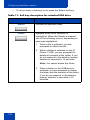
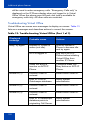
situation. The key functions in the menus are described in Table 5.
Table 5: Navigation key functions in the main menu
Key
Function
Left arrow
Navigates to the menu on the left.
Right arrow
Navigates to the menu on the right.
Up arrow
Moves the highlight bar up through the submenu
items.
74
Configuring Local Menu options
Table 5: Navigation key functions in the main menu
Key
Function
Down arrow
Moves the highlight bar down through the sub menu
items.
Enter or Select
softkey
Enter or Select softkey opens the submenu item.
Exit soft key
Exits the main menu and returns the Display to the
Telephony menu.
Table 6 describes the key functions in a dialog box.
Table 6: Navigation key functions in a dialog box
Key
Function
Enter
Opens the list of the highlighted item.
Up arrow
Scrolls the highlight bar up the list.
Down arrow
Scrolls the highlight bar up the list.
Select soft key
Selects the item.
Cancel soft
key
Cancels the selection.
Table 7 describes the key functions in the Edit mode.
Table 7: Navigation Key functions in the Edit mode
Key
Function
OK soft key or Enter
key
Saves the changes and closes the list.
Bkspc soft key
Backspaces a character.
Clear soft key
Clears the input.
Cancel soft key
Quits the list item edit without saving the
changes.
75
Configuring Local Menu options
Navigation using the USB mouse
If you are using a USB mouse, you can right-click the Telephony screen
to open the Local Tools menu, and then click an item to select it. You can
navigate through the menu items as follows:
•
Clicking the left or right arrows of the main menu moves the selection
of the main menu items to the left or right.
•
Clicking on a submenu item selects it, and causes a further dialog
box or menu to appear.
•
Clicking the label of a soft key triggers the function of the soft key.
•
Clicking in the blank space of the scroll bar above or below moves the
screen up and down.
Submenu dialog attributes
A submenu dialog box has the following attributes:
•
The top area displays a cookie crumb title that informs you where you
are in the menu structure. When the title is too long for the display, it
is truncated on the left.
Navigation using a mouse in a combo box
•
Clicking on the value of the item or the arrows of the box on the right
side opens the list.
•
If the item can be edited, the softkeys change to the edit softkeys; that
is, OK, BkSpc, Clear, and Cancel.
•
Clicking the left mouse button in the editable item moves the edit
cursor position.
•
Clicking the left mouse button on the arrows at the right side of the
box ends an edit (if editing), selects the current item, and closes the
list.
Preferences submenu
The Local Tools menu 1. Preferences submenu offers the following
choices:
76
Configuring Local Menu options
•
“1. Display Settings” on page 77
•
“2. Language” on page 88
•
“3. Headsets” on page 89
•
“4. Bluetooth” on page 93
•
“5. File Manager” on page 105
•
“6. Background” on page 113
1. Display Settings
The Display Settings menu provides control of the items related to the
display such as the contrast and brightness settings, the duration of the
backlight, the color theme used on the IP Phone, and the bolding of the
Expansion Module font. You can review the changes in the display before
saving them. The following table describes the items in the Display
Settings.
Table 8: Display Settings functions (Part 1 of 2)
Tool
Description
Contrast
Sets the contrast of the display.
Brightness
Sets the brightness of the display.
Backlight
Sets the duration for which the
backlight remains on when the IP
Phone is idle.
Slideshow
Sets the delay time for the slideshow to
begin after the IP Phone is idle.
Display Dim Enabled
When the backlight timer expires, the
display dims instead of turning
completely off.
Theme
Allows the selection of a predefined
theme for the display.
77
Configuring Local Menu options
Table 8: Display Settings functions (Part 2 of 2)
Tool
Description
Use Theme Background
The background image of the color
theme is used instead of a userprovided background. Uncheck this if
you want to use a user-provided
background.
Use Font Smoothing
Makes the font curves appear
smoother. Disabling this can improve
the appearance of some language’s
text on the display.
Use Outlined Font
Changes the telephony screen font of
the IP Phone to a white font with black
outline. Helps to make the text readable
when a user-provided background is
enabled.
GEM Bold Font
Controls whether the font in the
Expansion Module(s) (GEM) is bolded
or not.
Use Simple Icons
Changes the line or feature key icons to
ones similar to those on earlier IP
Phones.
Note: Changes you make to contrast in this menu are lost if the IP
Phone is reset. To avoid losing your changes, Nortel recommends
that you use the Contrast Adjustment control in the Telephone
Options menu.
Note: Changes to the GEM Bold Font or Use Simple Icons
checkboxes can cause the attached Expansion Modules (GEMs) to
reset after the Apply key is pressed. This is normal and allows the
Expansion Modules (GEMs) to refresh the display in a new format.
To adjust the display settings, press the Services key twice to open the
Local Tools menu. Press the 1 key on the dialpad to select
1. Display Settings.
78
Configuring Local Menu options
Using the Contrast or Brightness settings:
To use the contrast or brightness settings, press the Services key twice
to open the Local Tools menu. Press the 1 key on the dialpad to select
1. Display Settings.
Note: To increase the service life of the display:
– set the brightness below 3/4
– avoid using the “Always On” setting of the backlight timer value
1. Press the Up/Down navigation keys to choose one of the following:
— Contrast
— Brightness
2. Click the left/right arrow of the indication bar, or use the Left/Right
navigation keys to adjust the setting.
3. Choose one of the following:
— Press the Apply soft key to save changes.
— Press the Cancel soft key to dismiss the changes.
79
Configuring Local Menu options
Setting the Backlight Timeout Value:
To set the backlight timeout value, press the Services key twice to open
the Local Tools menu. Press the 1 key on the dialpad to select
1. Display Settings.
1. Press the Up/Down navigation keys to choose Backlight.
2. Click the left/right arrow of the indication bar, or use the navigation
keys to select the timeout value.
The values are as follows:
— 5 sec
— 1 min
— 5 min
— 10 min
— 15 min
— 30 min
— 1 hr
— 2 hr
— Always on
3. Choose one of the following:
— Select the Apply soft key or the Enter key to save changes.
— Select the Cancel soft key to dismiss the changes.
Using the Digital Picture Slideshow:
The new IP Phone 1165E has a digital picture slideshow feature. You can
copy or transfer images into the phone, and view a slideshow of them as
a screensaver. For more information, refer “Accessing the files on the IP
Phone 1165E” on page 105.
To use the digital picture slideshow feature, press the Services key twice
to open the Local Tools menu. Press the 1 key on the dialpad to select
1. Display Settings.
80
Configuring Local Menu options
1. Select the Slideshow settings using the Up/Down navigation keys or
the USB mouse.
2. Click the Left/Right arrow of the indication bar, or use the navigation
keys to select the timeout value.
The values are as follows:
— 1 min
— 5 min
— 10 min
— 15 min
— 30 min
— 1 hr
— 2 hr
— Off (default)
3. Choose one of the following:
— Select the Apply soft key or the Enter key to save changes.
— Select the Cancel soft key to dismiss the changes.
Using the Backlight Dim feature:
When Display Dim is enabled and the backlight timer expires, the
backlight dims to a low level instead of turning off completely.
To use the backlight dim feature, press the Services key twice to open
the Local Tools menu. Press the 1 key on the dialpad to select
1. Display Settings.
1. Select the Display Dim Enabled settings using the Up/Down
navigation keys or the USB mouse.
By default the check box is cleared.
2. Press the Enter key or use the USB mouse to toggle the check box.
3. Choose one of the following:
— Select the Apply soft key to save changes.
— Select the Cancel soft key to dismiss the changes.
81
Configuring Local Menu options
Setting a theme:
To set a theme, press the Services key twice to open the Local Tools
menu. Press the 1 key on the dialpad to select 1. Display Settings.
1. Select the Theme setting using the navigation keys or USB mouse.
2. Select a theme using the Left/Right navigation keys or the USB
mouse.
3. Choose one of the following:
— Select the Apply soft key to save changes.
— Select the Cancel soft key to dismiss the changes.
Note: You can select the colors of the soft key labels and text for a
user-provided background by selecting them from the themes and
they will be applied even though the theme is not selected.
Using the Background Theme:
To use the background theme, press the Services key twice to open the
Local Tools menu. Press the 1 key on the dialpad to select
1. Display Settings.
1. Select the Use Theme Background setting using the navigation
keys or USB mouse. By default, the check box is selected.
2. Use the Enter key or the USB mouse to clear or select the check box.
If you clear the check box, the IP Phone uses the image you have
selected or downloaded as the background of the IP Phone display. If
you select the check box, the IP Phone uses the color theme
background you have selected as the phone display background.
3. Choose one of the following:
— Select the Apply soft key to save changes.
— Select the Cancel soft key to dismiss the changes.
Using Font Smoothing:
To use the font smoothing, press the Services key twice to open the
Local Tools menu. Press the 1 key on the dialpad to select
1. Display Settings.
82
Configuring Local Menu options
1. Select the Use Font Smoothing setting using the Up or Down
navigation keys or USB mouse.
2. Use the Enter key or USB mouse to toggle the check box.
3. Choose one of the following:
— Select the Apply soft key to save changes.
— Select the Cancel soft key to dismiss the changes.
Using Outlined Font:
To use the outlined font, press the Services key twice to open the Local
Tools menu. Press the 1 key on the dialpad to select 1. Display Settings.
1. Select the Use Outlined Font setting using the navigation keys or
USB mouse.
2. Use the Enter key or USB mouse to toggle the check box.
3. Choose one of the following:
— Select the Apply soft key to save changes.
— Select the Cancel soft key to dismiss the changes.
Using the Expansion Module Bold Font:
Enabling this option bolds the font on the GEM display. Not bolding it may
make some text of language appear more clearly.
To use the Expansion Module bold font, press the Services key twice to
open the Local Tools menu. Press the 1 key on the dialpad to select
1. Display Settings.
1. Select the GEM Bold Font setting using the navigation keys or USB
mouse.
2. Use the Enter key or USB mouse to toggle the check box.
3. Choose one of the following:
— Select the Apply soft key to save changes.
— Select the Cancel soft key to dismiss the changes.
83
Configuring Local Menu options
Using the Simple Icons:
To change the type of icons, press the Services key twice to open the
Local Tools menu. Press the 1 key on the dialpad to select
1. Display Settings.
1. Select the Use Simple Icons setting using the navigation keys or
USB mouse.
2. Use the Enter key or USB mouse to toggle the check box:
— Enable check box to enable display of traditional icons on
Telephony screen.
— Clear check box to enable display of new icons on the telephony
screen.
3. Choose one of the following options:
— Select the Apply soft key to save the changes.
— Select the Cancel soft key to dismiss the changes.
Table 9 compares the new IP Phone 1165E icons to the simple icons.
Simple icons are listed under IP Phones 1120E/1140E/1150E graphical
grayscale displays column.
Table 9: Standard Nortel Icons (Part 1 of 5)
Free form icon
state
I-idle
U-Idle
I-Ring
84
IP Phones
1120E/1140E/1150E
graphical grayscale
displays
IP Phone 1165E
icons
Configuring Local Menu options
Table 9: Standard Nortel Icons (Part 2 of 5)
Free form icon
state
IP Phones
1120E/1140E/1150E
graphical grayscale
displays
IP Phone 1165E
icons
U-Ring
I-Active
U-Active
I-Hold
U-Hold
I-Group Listen
U-Group Listen
Feature Active
Feature
Inactive
85
Configuring Local Menu options
Table 9: Standard Nortel Icons (Part 3 of 5)
Free form icon
state
I-Hold Ringing
U Hold Ringing
Active Audio
Hold Audio
Home
Business
Extension
Number
Pager
Voice
86
IP Phones
1120E/1140E/1150E
graphical grayscale
displays
IP Phone 1165E
icons
Configuring Local Menu options
Table 9: Standard Nortel Icons (Part 4 of 5)
Free form icon
state
IP Phones
1120E/1140E/1150E
graphical grayscale
displays
IP Phone 1165E
icons
Fax
Email
Wireless
Internet
address
Set-to-Set
Message
Secured
Trash can
Inbox
Outbox
87
Configuring Local Menu options
Table 9: Standard Nortel Icons (Part 5 of 5)
Free form icon
state
IP Phones
1120E/1140E/1150E
graphical grayscale
displays
IP Phone 1165E
icons
Video
Other/Misc.
2. Language
The Language setting in the Preferences menu configures the language
used on the IP Phone display.
•
The language can also be configured under the Telephone options
menu. See “Configuring Telephone Options” on page 51.
•
To set the language using the Preferences menu, press the
Services key twice to open the Local Tools menu and press the 2
key on the dialpad to select 2. Language....
To select the language using the Language dialog:
1. Press the Up/Down navigation keys to
scroll and highlight the desired language
(for example, German [Deutsche]).
2. Choose one of the following:
OK
Cancel
or
— Press the OK soft key to save the
desired language, and return to the
Preferences menu.
— Press the Cancel soft key to keep
existing configurations.
88
Configuring Local Menu options
Exit
3. Press the Exit soft key to exit to the main
display.
3. Headsets
Use the Headsets tool to select the headset used on your IP Phone.
To select the headset used in the local menus, press the Services key
twice to open the Local Tools menu, and then press the 3 key on the
dialpad to select 3. Headsets...
Selecting an Active Headset Device
You can select Active Headset Device as Wired, USB, or Bluetooth
using the Active Headset Device option. Follow the procedure to select
an active headset device.
To select an active headset device
Enter
1. Press the Enter key to open the Active
Headset device list.
2. Press the Up/Down navigation keys to
scroll to one of the following Active
Headset Devices:
— Wired
— USB
— Bluetooth
Select
Cancel
or
3. Press Select for the desire device or
press Cancel to keep existing
configurations
89
Configuring Local Menu options
4. Press the OK soft key to save the
desired headset selection and return to
the Preferences menu.
Note: You can select a headset
regardless of its connection status. It
does not have to be physically
connected to the IP Phone 1165E.
Exit
5. Press the Exit soft key to exit to the main
display.
Enabling a USB headset
For a list of supported headsets that provide acceptable audio
performance with the IP Phone 1165E, go to www.Nortel.com.
Figure 20: Headset menu item display
To enable a USB headset
Making a change in the Headset menu page takes effect immediately.
90
Configuring Local Menu options
Note: Press the Apply button to make the changes permanent.
Press Exit to discard any changes.
1. Select USB from the Active Headset Device list.
2. Select the Enable HID Commands check box to provide full HID for
supported headsets.
Note: The following two steps applies only if the Nortel Headset
Adapter is connected. You can select the Headset Type only for the
Nortel USB Headset Adapters. If the Nortel USB Headset Adapter is
not detected, the Headset Type selection is disabled, and cannot be
modified.
3. Select the Headset type from the following list of headsets:
•
DuraPlus-B (GN Netcom DuraPlus Binaural Headset)
•
DuraPlus-M (GN Netcom DuraPlus Monaural Headset)
•
GN2020 (GN Netcom GN2020 NC Monaural Headset)
•
GN2100 (GN Netcom GN2100 Monaural Headset)
•
GN2115 (GN Netcom GN2115 ST Binaural Headset)
•
GN2117 (GN Netcom GN2117 ST Monaural Headset)
•
GN2125 (GN Netcom GN2125 NC Binaural Headset)
•
GN2220 (GN Netcom GN2220 NC Monaural Headset)
•
GN2225 (GN Netcom GN2225 NC Binaural Headset)
You can select and configure a headset type regardless of whether the
headset is plugged in or not to the Nortel USB Headset Adapter.
4. Select the Back Light check box to control the backlight on the Nortel
USB Headset Adapters. This check box is selected by default.
5. Press Apply to save the changes and return to the previous menu or
press Exit to discard any changes and return to the previous menu.
Limitations and advisories
•
USB headsets consume power from the USB port in order to operate.
The USB port on the IP Phone imposes a limit of only 100mA if PoE
(Power over Ethernet)-powered and 500 mA if local AC-powered. The
91
Configuring Local Menu options
limit of 100mA is sufficient to power the Nortel USB Headset
Adapters.
•
USB Audio support does not include stereo audio.
•
For the Nortel USB Adapters, it is a requirement that the firmware of
this device be V2.0.32 or later.
•
For the Algo 4900 USB ATA, it is a requirement that the firmware of
this device be v1.00.32 or later.
•
The Algo 4900 USB ATA is classified as a high-power device. It can
be powered directly by an 1165E IP Phone only if the phone is
powered by the AC Adapter. If the IP Phone is powered by PoE then
the Algo 4900 USB ATA must be connected through a powered USB
hub.
Nortel Mobile Headset Adapter properties
You can use the Nortel Mobile Headset Adapter to answer calls on the
IP Phone 1165E.
To access the Nortel Mobile Headset Adapter (MHA) properties (Headset
type and Backlight options), press the Services key twice to open Local
Tools and press the 3 key on the dialpad to select 3.Headsets....
Note: The Headset type and Backlight options can be modified only
when the MHA is attached.
Table 10 describes the features of the Nortel Mobile Headset Adapter.
Table 10: Nortel Mobile Headset Adaptor elements and
functions (Part 1 of 2)
Key
Function
Answer key
Press to answer an incoming call.
If there is no incoming call, the IP 1165E
handset selects a line, and you hear a dial
tone. This is also referred to as Off-hook.
Release/Goodbye key
92
This is also referred to as On-hook.
Configuring Local Menu options
Table 10: Nortel Mobile Headset Adaptor elements and
functions (Part 2 of 2)
Key
Function
Mute key
Press the Mute key to listen to the receiving
party without transmitting.
Press the Mute key again to return to twoway conversation.
Volume key
Use the Volume buttons to increase or
decrease the volume of the headset.
Backlight
The backlight illuminates when you connect
your headset to the IP Phone 1165E.
4. Bluetooth
Your IP Phone 1165E is equipped with a radio system to support
Bluetooth wireless technology enabled headsets. Double-press the
Headset key to open the Bluetooth Setup dialog box. You must be
familiar with the operation of the navigation keys to work in the Bluetooth
Setup dialog box. See the Navigation keys description.
The Bluetooth Setup menu entry is not available on all IP Phones. If the
Bluetooth Setup menu entry appears dimmed, or fails to open when you
double press the Headset key, the feature is not enabled on your IP
Phone. Before you can use a wireless headset with your IP Phone, the
feature must be enabled by the system administrator. Contact your
administrator to find out if Bluetooth wireless technology functionality is
available for your use.
Note: Nortel recommends that you not pair more than one headset of
the same model, as they have identical names in the Paired list.
93
Configuring Local Menu options
Figure 21: Bluetooth Setup screen
To pair a wireless headset with your IP Phone:
(Headset)
1. Double-press the Headset key to open
the Bluetooth Setup dialog box.
The Enable Bluetooth check box is
highlighted.
If the Bluetooth Setup menu fails to open
when you double press the Headset key,
Bluetooth wireless technology feature is
not enabled on your phone. Contact your
administrator.
2. Press the Enter key to activate
Bluetooth wireless technology.
A check mark is displayed on the Enable
Bluetooth item to indicate that the
Bluetooth wireless technology is
activated. The message “Bluetooth
Enabled” appears at the bottom of the
display.
94
Configuring Local Menu options
3. Put your Bluetooth wireless technology
headset in its pairing or search mode.
The procedure for doing this can be
different for each headset. Refer to the
documentation that accompanied your
headset, or contact the vendor.
95
Configuring Local Menu options
4. Search devices.
a. Ensure that your headset is in
Pairing or Search Mode.
b. Press the Right navigation key
twice, and highlight the Search
button, displayed next to the Search
Devices item.
c.
Press the Enter key.
The message "Searching…." appears. It
can take up to two minutes for the
search to complete.
If the search is successful, the message
"Search Completed Found Device(s)"
appears, and a list of devices that
support Bluetooth wireless technology
appears in the Found: list.
d. Choose one of the following:
— If the search is successful, proceed
to Step 5.
— If the search is not successful, the
message "Search completed. No
device found" appears. If this
happens, or if the headset times out
and exits search/pairing mode,
power off the headset, and repeat
Step 3 and Step 4.
If pairing is still unsuccessful, pair
the IP Phone to another wireless
headset, or contact the headset
vendor.
96
Configuring Local Menu options
Stop
5. When the name of your headset appears
in the Found: box, press the Stop soft
key or wait for the search to finish. When
the search is complete, the message
"Search Completed Found Device(s)"
appears.
6. Choose one of the following:
•
If the name of your headset appears in
the Found: box, proceed to Step 7.
•
If your headset is not displayed in the
Found: box, select your headset from
the list, as follows:
a. Press the Right navigation key one
or more times to highlight the
Found: box. Press the Enter key to
start the edit mode.
b. Press the Down navigation key to
open the Found: list. Press the Up/
Down navigation keys to scroll and
highlight your headset.
c.
Press the Enter key to select the
headset and close the list. Press the
Enter key to exit edit mode.
97
Configuring Local Menu options
7. Press the Right navigation key one or
more times to highlight the Pair button
(next to the Pair Device item) and press
the Enter key.
a. A dialog box appears, with the
prompt "Enter PIN#".
b. Use the phone dialpad to enter the
PIN for the wireless headset and
press the Enter key.
Check your headset documentation
to find its PIN (sometimes called a
passkey). Typically this value is
0000.
98
Configuring Local Menu options
8. Choose one of the following:
•
If the headset is successfully paired with
your IP Phone, proceed to Step 9. To
verify that the pairing was successful,
ensure that the headset appears in the
list next to the Paired: item. If pairing is
successful, the message "Pair
completed" also appears at the bottom
of the screen.
•
If the headset is not successfully paired
with your IP Phone, an error message
appears at the bottom of the screen. If
an error message appears:
— Confirm that the wireless headset is
still in search/pair mode.
— If the headset timed out and exited
search/pairing mode, put the
headset in pairing mode, as
discussed in Step 3 and Step 7.
— Check that you are using the correct
PIN and repeat Step 7.
99
Configuring Local Menu options
9. Choose one of the following:
•
If the name of your headset appears in
the Paired: box, proceed to Step 10.
•
If more than one device is paired, and
the one you wish to use is not shown in
the Paired: box, navigate to the one you
want, as follows:
a. Press the Right navigation key one
or more times to highlight the
Paired: box. Press the Enter key to
start the edit mode.
b. Press the Up/Down navigation keys
to open the list. Press the Up/Down
navigations key to scroll in the
Paired: list and highlight your
headset.
c.
100
Press the Enter key to select the
headset and close the list. Press the
Enter key to exit edit mode.
Configuring Local Menu options
10. Choose one of the following:
•
If only one headset is paired, proceed to
Step 11.
•
If more than one wireless headset is
paired, the first headset paired is
automatically made the active device. To
make a different headset active, do the
following.
— Press the Right navigation key one
or more times to highlight the Set
button (next to the Set Active Device
item).
— Press the Enter soft key.
The message "Set active: “device name”
appears. This means the headset
named is now the active headset and is
used when you press the headset key.
Exit
11. Press the Exit soft key to exit to the main
display. Changes are saved
automatically.
Dual Pairing Headsets
Take special care when using a "dual pairing" type of Bluetooth wireless
technology headset, which can be paired to its base as well as to the IP
Phone 1165E. If it is paired to both, the IP Phone 1165E is the second
device, and the following applies:
Press the headset "telephone" key:
•
If a single tone sounds, the headset is connected to the base.
•
If a double beep sounds, the headset is connected to the IP Phone
1165E.
101
Configuring Local Menu options
If the base is powered off, the headset is only paired to the IP Phone
1165E and pressing the "telephone" key connects you to the IP Phone
1165E.
Note: Unless you need to dual pair a headset, operating the headset
with the IP Phone 1165E is simpler if the headset is only used with its
charging-only base. The desktop IP Phone base should be powered
off if it is not in use.
Interaction with wired headsets
If you connect a Bluetooth wireless technology headset and a wired
headset to the same IP Phone 1165E, the “Use Bluetooth headset” item
switches between the wired headset and the Bluetooth headset. If you
select the “Use Bluetooth Headset” check box, the Bluetooth headset
provides the audio. If you clear the “Use Bluetooth Headset” check box,
the wired headset provides the audio.
The Bluetooth wireless technology headset can work only if it is within
range of the IP Phone; as the wireless headset approaches the edge of
its radio range, the audio quality degrades and radio interference noise
increases. When the wireless headset is in connecting range, the
Headset key controls the wireless headset, even if a wired headset is
attached. If a wireless headset moves out of connecting range, a special
beep sounds in the headset indicating the connection was lost.
When you do not want to use your Bluetooth wireless technology
headset
If a Bluetooth wireless technology headset is connected, and you want to
use the wired headset, you can switch between the two. It is not
necessary to unpair or disable the wireless headset.
You can switch between a wired and wireless headset and back again
either when the IP Phone is idle or during an active call.
To switch between a wired headset and a wireless headset:
(Headset)
102
1. Double-press the Headset key to open
the Bluetooth Setup dialog.
Configuring Local Menu options
2. Press the Left/Right navigation key to
select the “Use BT Headset” item.
3. Press the Enter key to toggle this option
on or off.
A check mark indicates that the wireless
headset is used. Clear the check mark to
use a wired headset. This option is on
(o) by default.
To unpair a wireless headset:
(Headset)
1. Double-press the Headset key to open
the Bluetooth Setup dialog box.
2. Press the Right navigation key to select
the Paired: item.
103
Configuring Local Menu options
3. Choose one of the following:
•
If the name of your headset appears in
the Paired box, proceed to Step 5.
•
If more than one device is paired, and
your headset is not already displayed in
the Paired box, do the following:
a. Press the Right navigation key one
or more times to highlight the Paired:
box. Press the Enter key to open
edit mode.
b. Press the Up/Down navigation keys
to open the list. Press the Up/Down
navigations key to scroll in the list
and highlight your headset.
c.
Press the Enter key to select the
headset and close the box. Press
the Enter key to exit edit mode.
4. Press the Right navigation key one or
more times to highlight the UnPair button
(next to the UnPair Device item).
5. Press the Enter key.
Your Bluetooth wireless technology
headset is unpaired and removed from
the Paired: item list.
Your Bluetooth wireless technology headset is no longer paired with your
IP Phone, and the wired headset can be used. To use the wireless
headset again, you must perform the pairing and activation procedure.
104
Configuring Local Menu options
5. File Manager
The File Manager menu item provides access to files on the IP Phone
1165E and access to files on the USB drive, if one is attached. The
screen that appears depends on whether a USB drive is attached.
If a USB drive is not attached, a screen appears that lets you browse the
contents of the file system on the IP Phone. From this screen you can
also delete files that are on the phone. For more information, see
“Accessing the files on the IP Phone 1165E” on page 105
If a USB device is attached, a screen appears that lets you browse the
contents of the file system on the IP Phone and an attached USB drive.
You can copy images to and from a USB drive to your IP Phone. You can
delete files from the IP Phone as well as from the USB drive when using
the file manager.
Accessing the files on the IP Phone 1165E
Use the following procedures to access the files on the IP Phone 1165E
or an attached USB device.
To access files without USB drive attached to the phone:
1. Select File Manager from the Preferences menu of the IP Phone
1165E.
2. Highlight the Phone directory and click the Select soft key.
105
Configuring Local Menu options
Figure 22: File Manager Device Selection dialog–no USB
device
3. Press the Up/Down navigations key to scroll the list, and highlight the
folder that you want to access.
4. Do one of the following:
— Press the Select soft key to access the selected folder.
— Press the Delete soft key to delete the contents of the folder.
Only the contents within the folder are deleted.
— Press the Back soft key to move up a level in the directory
structure or to return to the Device Selection dialog if you are at
the top directory.
106
Configuring Local Menu options
To access the file with USB drive attached to the phone
1. Select File Manager from the Preferences menu of the IP Phone
1165E. The screen shows the device selection dialog with the phone
and the USB device. See Figure 23 on page 107.
Figure 23: File Manager device selection dialog–with USB
device
2. Press the Up/Down navigations key to highlight the device (IP Phone
or USB drive) that you want to access.
3. Press the Select soft key to display the folders/files in the device.
4. Press the Up/Down navigation key to scroll through the list, and
highlight the files or directory that you want to access on the IP Phone
or the USB drive.
— To send a file to the phone from the USB drive, press the Send
soft key.To delete a file from the USB drive, highlight the file, and
press the Delete soft key.
— To move up a directory level on the device, press the Back soft
key or highlight “..”, then press the Select soft key. When you are
at the root menu, this returns you to the Device Selection dialog.
107
Configuring Local Menu options
— To move down a directory level, press the Select soft key.
Table 11: Soft key description for attached USB drive
Select
Access the selected folder.
Delete
Appears when file or directory is
highlighted. When the Delete is pressed,
one of the following occurs, depending on
what was highlighted:
1. When a file is selected, you are
prompted to delete the file.
2. When a folder is selected on the IP
Phone 1165E, you are prompted to
delete all contents of the folder. If you
do not respond to the deletion prompt,
deletion is canceled in 15 seconds.
Note: You cannot delete the folder.
3. When a folder on the USB drive is
selected, you are prompted to delete
the folder and the contents of the folder.
If you do not respond to the deletion
prompt, deletion is canceled in 15
seconds.
108
Configuring Local Menu options
Table 11: Soft key description for attached USB drive
Send
Appears only when a file is selected.
1. When a file on the USB drive is
selected, you can press Send to copy
this file to the IP Phone 1165E. The
destination folder is automatically
selected based on the type of file. For
example, JPG files are sent to the
Images folder on the IP Phone 1165E.
2. When a file on the IP Phone 1165E is
selected and no USB drive is attached,
an error displays on the screen.
Note: Copying files from one location
on the phone to another location on the
IP Phone 1165E is not supported.
3. When a file on the IP Phone 1165E is
selected while a USB drive is
connected, you can navigate to the
USB folder where you want to copy the
file.
Back
Navigates to the previous directory level.
Cancel
Cancels the operation and returns to the
prior dialog.
Sending a file from the phone to the USB drive
Use the following procedure to send a file from the phone to the USB
drive.
109
Configuring Local Menu options
To send a file from the phone to the USB drive
1. Press the Services key twice to open the Local Tools menu. Press
the 5 key on the dialpad to select File Manager from the
Preferences menu of the IP Phone 1165E.
The screen shows the folders and the USB devices on the phone.
See Figure 23 on page 107
2. Browse for and select the file on the phone that you want to send to
the USB drive.
3. Press Send.
The Select Destination screen opens. See Figure 24 on page 110.
Figure 24: Select Destination screen
4. Press OK to open the destination folder.
Or
Press Cancel to return to the previous screen.
5. Press the Up/Down navigation key to scroll through the list, and
highlight the directory on the USB drive where the files are to be
copied.
— To select the current location as the destination, press the Done
soft key.
110
Configuring Local Menu options
— To move up a directory level on the device,.press the Back soft
key or highlight “..”, then press the Select soft key.
Send Results
When the OK soft key is pressed, the IP Phone attempts to process the
selected file.
Figure 25 on page 111 shows a successful send operation.
Figure 25: Successful send operation
Figure 26 on page 112 shows an unsuccessful send operation.
111
Configuring Local Menu options
Figure 26: Failed send operation
Sending an image file from a USB drive to the phone
Use the following procedure to send an image file from the USB drive to
the phone.
1. Plug the USB flash drive into the phone's USB port.
2. Press the Services key twice to open the Local Tools menu. Press
the 5 key on the dialpad to select File Manager from the
Preferences menu.
3. Select the USB Flash Drive device and press the Enter key. The
device directories/files are displayed.
4. Browse to select the file your image and press the Send soft key. You
are prompted to send file.
5. Press the OK soft key at the confirmation prompt. The image file is
copied to the IP phone's Images directory.
6. A success message is displayed explaining that the file has been
copied. Press OK.
Additional information
This section provides additional information for the File Manager.
112
Configuring Local Menu options
•
To move up a directory level, press the Back soft key or highlight “..”,
then press the Select soft key. When you are at the root menu, this
returns you to the Device Select dialog
•
Based on the file extension, validation routines run to verify, for
example, size and free space available.
•
Files with unknown extensions are not supported.
•
The screensaver and background images must be a 320*240 pixel 24
bit portable network graphic (PNG) or joint photograph experts group
(JPEG).
•
The image files screensaver must be named screensaverN.png or
screensaverN.jpg.
•
“In progress…” appears on the screen for actions that take time to
complete.
6. Background
The IP Phone 1165E allows the display of user selected background
images. This Preferences menu item enables you to browse the currently
stored images and select the desired image.
Press the Services key twice to open the Local Tools menu. Press the 6
key on the dialpad to select 6. Background.
Figure 27 on page 114 displays the Background Image screen.
113
Configuring Local Menu options
To select an image for the background
Figure 27: Background Image screen
1. From the Background menu, press the Up/Down navigations key to
scroll the list, and highlight the image that you want to appear.
As you navigate the list, each file image appears in the background
as a preview of how it would look as the background image.
2. Press the Select soft key.
For more information, See “Using the Background Theme:” on page 82.
Diagnostics
To access the Diagnostics submenu, press the Services key twice and
then select the Diagnostics submenu. The Diagnostics submenu offers
the following choices:
•
“1. IP Set Information” on page 115
•
“2. Network Diagnostic Tools” on page 115
•
“3. Ethernet Statistics” on page 115
•
“4. IP Network Statistics” on page 115
114
Configuring Local Menu options
•
“5. USB Devices” on page 115
•
“6. Advanced Diag Tools” on page 118
•
“7. DHCP Information” on page 118
•
“8. License Information” on page 118
•
“9. VPN Information” on page 118
•
“10. Certificate Information” on page 119
Press the Return soft key at any time while working with tools in the Local
Diagnostics submenu to return to the Local Diagnostics submenu. Use
the Return key in this way to quickly gather information and run tests
without exiting and reentering the Local Tools menu. For example, you
can check the Ethernet Statistics, then press Return and enter the
Network Diagnostics Tools to ping an IP address.
1. IP Set Information
The Network Configuration tool is used to view reports about IP set and
DHCP operation. This tool is for administrator use only.
2. Network Diagnostic Tools
The Network Diagnostic Tools menu contains tools that are used to
diagnose network problems. This menu is for administrator use only.
3. Ethernet Statistics
The Ethernet Statistics tool is used to view reports about Ethernet
operation. This tool is for administrator use only.
4. IP Network Statistics
The IP Networks Statistics tool is used to view reports about network
operation. This tool is for administrator use only.
5. USB Devices
The USB Devices tool provides information about any Universal Serial
Bus (USB) devices that you connect to your phone. Your IP Phone 1165E
automatically detects USB devices when you connect them to the USB
port in the back of the IP Phone.
115
Configuring Local Menu options
To check USB device information, press the Services key twice to open
the Local Tools menu, press the 2 key on the dialpad to select
2. Local Diagnostics, and press the 5 key on the dialpad to select
5. USB Devices.
To check USB device information:
The screen displays information about
connected devices.
Cancel
1. Press the Cancel soft key to cancel to
the main display.
If the USB port has been disabled, no devices are enumerated and the
screen displays only that the USB port is disabled, even if USB devices
are connected.
Figure 28 on page 117 shows the IP Phone display when the USB port is
disabled.
116
Configuring Local Menu options
Figure 28: USB Devices—Port Disabled
If the USB port is enabled, then you can attach any USB 1.1 or 2.0compliant devices to the IP Phone, and the display shows what USB
devices are attached to the IP Phone, even if the device is not supported
by the IP Phone 1165E, or if the device type is locked. Locked devices do
not function on the IP Phone even if they are enumerated.Your
administrator selects what USB devices can be used on the IP Phone. If
certain USB devices are locked (that is, they cannot be used), then the
screen displays that information.
See Figure 29 on page 118 for information on the available locks.
117
Configuring Local Menu options
Figure 29: USB Devices—locked devices
6. Advanced Diag Tools
The Advanced Diag Tools are available to the Nortel support organization
to configure the auto recovery function and remote access. This tool is for
system administrator use only.
7. DHCP Information
The system administrator can use the DHCP Information menu to view
license information. This menu is for system administrator use only.
8. License Information
You can use License Information menu to view license information. This
menu is for administrator use only.
9. VPN Information
The system administrator can use the VPN Information menu to view
VPN information. This menu is for system administrator use only.
118
Configuring Local Menu options
10. Certificate Information
The system administrator can use the Certificate Information menu to
view certificate information. This menu is for system administrator use
only.
Configuration
To access the Configuration menu, press the Services key twice, and
then select the Configuration submenu. The Configuration menu offers
the following choices:
•
“1. Network Configuration” on page 119
•
“2. Advanced Diag Tools” on page 120
Figure 30 on page 119 displays the Configuration submenu.
Figure 30: Configuration submenu display
1. Network Configuration
The Network Configuration tool displays information that was configured
when the IP Phone was installed. This tool is for administrator use only.
119
Configuring Local Menu options
2. Advanced Diag Tools
The Advanced Diagnostics Tool allows you to configure advanced
diagnostic tools. This tool is for administrator use only.
Locks
Your system administrator can use the lock menu tool to protect the Local
Tools menu items from accidental or unwanted changes. This tool is for
administrator use only. The Locks menu offers the following choices:
•
“1. Lock menu” on page 120
•
“2. USB Locks” on page 121
Figure 31 on page 120 displays the Locks submenu.
Figure 31: Locks submenu display
1. Lock menu
The Lock menu allows the administrator to lock the access of some or all
local menu items.
120
Configuring Local Menu options
2. USB Locks
USB Access Control (USB Lock) defines how you can use the USB port
on the IP Phone. You can completely disable the USB port, or you can
enable the USB port for various devices.
If the USB Port is disabled, the USB host controller does not initialize and
USB devices are not enumerated. The USB Devices dialog shows only
that the USB port is disabled.
USB Lock status can be determined by accessing the Local Tools menu
and selecting Locks. This screen is accessed through the Locks menu by
selecting “USB Locks”. Only the system administrator can access this
menu item when either Full lock or Partial lock is active.
AutoProvision USB Locks
This check box decides whether the USB locks are manually controlled or
set by zero touch provisioning feature.
Enable USB Port
This check box allows you to enable or disable the USB port.
Lock USB Mouse
This check box allows you to lock or unlock the USB mouse support.
Lock USB Keyboard
This check box allows you to lock or unlock the USB keyboard support.
Lock USB Headset
This check box allows you to enable or disable the USB headset support.
Lock USB Flash Drive
This check box allows you to lock or unlock the USB flash drive support.
121
Making a call
Making a call
This section describes features associated with making a call. You can
make a call from your IP Phone 1165E using any of the following:
•
“Using Off-hook dialing” on page 122
•
“Using On-hook dialing” on page 123
•
“Using handsfree dialing” on page 124
•
“Using the Directory applications” on page 126
•
“Using Predial” on page 129
•
“Using AutoDial” on page 130
•
“Using Ring Again” on page 131
•
“Using Last Number Redial” on page 133
•
“Using Speed Call” on page 133
•
“Using System Speed Call” on page 134
•
“Using HotLine” on page 135
•
“Using intercom calling” on page 135
Using Off-hook dialing
Use these steps to make a call by lifting the handset before dialing:
1. Lift the handset.
2. Dial the number.
122
Making a call
3. To terminate the call, choose one of the
following:
— Return the handset to the cradle.
or
— Press the Goodbye key.
(Goodbye)
Using On-hook dialing
Use these steps to make a call by dialing before lifting the handset:
1. Leave the handset in the cradle.
2493
2. Press the line (DN) key.
3. When the dial tone sounds, dial the
number.
4. When the called party answers, lift the
handset.
5. To terminate the call, choose one of the
following:
or
— Replace the handset into the cradle.
— Press the Goodbye key.
(Goodbye)
123
Making a call
Using handsfree dialing
Use handsfree dialing to use a built-in microphone and speaker, or a
headset, instead of the handset. While on an active call, you can switch
between handset and handsfree mode.
1. Choose one of the following:
— Press the Handsfree key.
or
— If a headset is connected, press the
Headset key.
2. Dial the number.
To use a headset:
1. Ensure the headset is connected to the
headset jack or the handset jack.
2. Press the Headset key.
If you have a Bluetooth wireless
technology headset installed, you can
activate it by pressing the button on the
headset.
To discontinue a handsfree call:
Press the Goodbye key.
(Goodbye)
124
Making a call
To mute a handsfree call:
(Mute)
(Mute)
1. Press the Mute key. The LED indicator
flashes.
2. Press the Mute key again to return to a
two-way handsfree conversation.
To switch from handsfree to handset mode:
Lift the handset.
To switch from handset mode to handsfree mode:
1. Press the Handsfree key.
2. Replace the handset.
To switch from handsfree to headset:
1. Press the Headset key.
125
Making a call
To release a call:
(Goodbye)
1. Press the IP Phone Goodbye key or
press the button on the headset, if
equipped.
Using the Directory applications
You can make calls using the following Directory applications available on
your IP Phone 1165E.
•
“Making a call using the Corporate Directory” on page 126
•
“Making a call using the Personal Directory” on page 127
•
“Making a call using the Callers List” on page 128
•
“Making a call using the Redial List” on page 129
Making a call using the Corporate Directory
This feature is not available on all phones. Contact your system
administrator to find out if this feature is available for your use.
The Corporate Directory feature provides an alphabetical list of entries
using last names. You can search by name, view additional information
on each entry, and dial Corporate Directory numbers. To use the
Corporate Directory, press the Directory key and select Corporate
Directory.
To search for a specific number:
1. When prompted, use the dialpad to enter
the desired name in the last name,
first name format.
126
Making a call
Search
2. Press the Search soft key to find the
desired name.
If the search is successful, the first
match appears on the screen.
3. Choose one of the following:
— Press the Dial soft key to dial the
resulting number.
Dial
— If there is no match to the search
query, start a new search or change
the information in the initial search.
Cancel
— Press the Cancel soft key to exit
without dialing.
To scroll to a specific number:
1. Press the Up/Down navigation keys to
scroll and highlight a name in the
Corporate Directory.
2. Choose one of the following:
Dial
Cancel
or
— Press the Dial soft key to dial the
resulting number.
— Press the Cancel soft key to exit
without dialing.
Making a call using the Personal Directory
The Personal Directory feature allows you to store a maximum of 100
entries consisting of names and numbers. To use the Personal Directory,
press the Directory key and select Personal Directory. For more
information on how to configure and use the Personal Directory, refer to
“Using the Personal Directory” on page 175.
127
Making a call
To make a call using the Personal Directory:
1. Press the Up/Down navigation keys to
scroll and highlight a name in the
Personal Directory.
2. Choose one of the following:
Dial
Cancel
or
— Press the Dial soft key to dial the
resulting number.
— Press the Cancel soft key to exit
without dialing.
Making a call using the Callers List
The Callers List feature automatically stores up to a maximum of 100
callers. After 100 callers have been stored, each additional caller
overwrites the oldest entry. To use the Callers List, press the Directory
key and select Callers List. For information on how to configure and use
the Callers List, see “Using the Callers List” on page 178.
To make a call using the Callers List:
1. Press the Up/Down navigation keys to
scroll and highlight a name in the
Callers List.
Note: If the caller name is not defined,
then only the telephone number is
displayed.
2. Choose one of the following:
Dial
Cancel
or
— Press the Dial soft key to dial the
resulting number.
— Press the Cancel soft key to exit
without dialing.
128
Making a call
Making a call using the Redial List
The Redial List feature automatically stores a maximum of 20 previously
dialed IP Phone numbers. To use the Redial List, press the Directory key
and select Redial List. For information on how to configure and use the
Redial List, see “Using the Redial List” on page 180.
To make a call using the Redial List:
1. Press the Up/Down navigation keys to
scroll and highlight a name in the Redial
List.
Note: If the caller name is not defined,
then only the telephone number is
displayed.
2. Choose one of the following:
Dial
Cancel
or
— Press the Dial soft key to dial the
resulting number.
— Press the Cancel soft key to exit
without dialing.
Using Predial
Use the Predial feature to enter, preview, and edit numbers before
dialing.
To use Predial:
1. Without selecting the line key, enter the
number to be dialed.
2498
2. Press a line key to dial the number.
129
Making a call
3. Lift the Handset when the called party
answers or, if in handsfree mode, begin
to speak.
To edit a Predial number:
1. Use the dialpad to enter the number.
2. Choose one of the following:
Clear
— To erase all numbers, press the
Clear soft key. Re-enter the
numbers to be dialed.
Delete
or
— To change one number at a time,
press the Delete soft key to
backspace. Re-enter the number.
2498
3. Press a line key to dial the number.
Using AutoDial
Use the AutoDial feature to display, store, and automatically dial phone
numbers.
To store an AutoDial number:
Autodial
1. Without lifting the handset, press the
appropriate AutoDial key.
The screen displays the word Autodial
next to the appropriate key.
130
Making a call
2. Using the dialpad, dial the phone
number (including access code) to be
stored on the selected AutoDial key.
Autodial
3. Press the AutoDial key a second time to
store the number on the selected key.
After you store a number, the word
Autodial disappears, and the stored
number appears.
4. Assign a label to the key.
After you assign the label, the number
disappears and only the label appears
on the screen next to the key.
To use AutoDial:
1. Lift the handset.
Autodial
2. Press an AutoDial key in the upper
display area to dial the number
associated with that key.
Using Ring Again
Use the Ring Again feature if you receive a busy tone, or if there is no
answer. Your IP Phone rings when the person you called becomes
available. Ring Again automatically redials the number.
131
Making a call
To activate Ring Again:
1. Dial a number and receive a busy tone
or no answer.
2. Choose one of the following:
RingAgn
— Press the RingAgn soft key.
— Enter the Ring Again Activate FFC.
or
To call a Ring Again party when you receive notification:
1. After receiving the notification ring, lift
the handset, or, if you are using the
headset or in handsfree mode, go to
Step 2.
>RingAgn
2. Press the RingAgn soft key to
automatically dial the number.
To deactivate Ring Again before notification:
>RingAgn
or
132
Choose one of the following:
•
Press the RingAgn soft key a second
time.
•
Press the Ring Again Deactivate FFC.
Making a call
Using Last Number Redial
Use the Last Number Redial feature to automatically redial the last dialed
number.
To use Last Number Redial:
Choose one of the following:
— To redial using the handset:
a. Lift the handset.
b. Press the line (DN) key.
2498
or
— To redial without lifting the handset,
press the line (DN) key twice (the
last number dialed is automatically
redialed).
2498
Using Speed Call
Use the Speed Call feature to place internal and external calls by dialing a
one-, two-, or three-digit code to store, edit, and automatically dial
frequently called phone numbers.
To store a Speed Call number:
SpcCtl
1. Press the Speed Call Controller soft
key. The triangular icon flashes,
indicating programming mode.
133
Making a call
2. At the prompt:
— Enter a one-, two-, or three-digit
code (0-999).
— If required, dial the access code.
— Enter the phone number (internal,
external, or long-distance number).
SpcCtl
3. Press the Speed Call Controller soft
key again to save the code and number.
The flashing icon turns off.
To make a Speed Call:
1. Lift the handset.
SpcCtl
2. Press the Speed Call Controller soft
key.
3. Dial the Speed Call code to
automatically dial the number.
Using System Speed Call
Use the System Speed Call feature to dial Speed Call codes that override
dialing restrictions placed on your IP Phone.
134
Making a call
To make a System Speed Call:
1. Lift the handset.
2. Choose one of the following:
SScUsr
SScCtl
— Press the System Speed Call soft
key.
or
— Press the System Speed Call
Controller (SScCtl) soft key.
3. Dial the Speed Call code to
automatically dial the number.
Using HotLine
Use the HotLine feature to automatically dial a specific number.
To use HotLine:
Hotline
Press the HotLine soft key to automatically
dial the number.
Using intercom calling
Use the Intercom feature to call a member of your intercom group by
pressing the code assigned to each member.
135
Making a call
To make an intercom call:
1. Lift the handset.
Intrcm
2. Press the Intercom key.
3. Dial the one- or two-digit code for the
desired intercom group member.
To answer an intercom call while on a line other than your intercom
group line:
1. Choose one of the following keys:
(Hold)
or
(Goodbye)
Intrcm
136
— Press the Hold key to put the current
call on hold.
— Press the Goodbye key to end the
call.
2. Press the Intercom key and begin to
speak.
Answering a call
Answering a call
Each incoming call causes the IP Phone to ring, the LCD indicator beside
the line (DN) key to flash, and the Message Indicator lamp to flash.
To answer a call:
Choose one of the following four options:
•
Lift the handset.
•
Press the Handsfree button located on
the left side of the IP Phone.
•
Press the line (DN) key beside the LCD
indicator as it flashes.
•
Press the Headset key if a headset is
connected to your IP Phone.
or
or
or
137
While on an active call
While on an active call
You can use the following features during an active call:
•
“Placing a call on hold” on page 138
•
“Transferring a call” on page 139
•
“Using Timed Reminder Recall” on page 140
•
“Using Attendant Recall” on page 141
•
“Using Call Park” on page 141
•
“Recording a Calling Party Number” on page 144
•
“Displaying incoming calls” on page 144
•
“Tracing a malicious call” on page 145
Placing a call on hold
Use the Hold feature when you are talking on one line and another call
arrives on a second line. To retain the original call, put it on hold and then
answer the second call.
To place a call on hold:
Press the Hold key. The LCD indicator
flashes beside the line on hold.
(Hold)
Note: If Automatic Hold is enabled, the
active call is automatically put on hold
when you answer the second call.
To retrieve a call on hold:
Press the line (DN) key beside the flashing
LCD indicator.
138
While on an active call
Transferring a call
Use the Transfer feature to redirect a call to the appropriate person.
To transfer a call to a third party:
Trans
1. Press the Transfer soft key. The other
party is put on hold and a dial tone
sounds. The LCD indicator light flashes
steadily.
2. Dial the DN number to which you are
transferring the call or use the Personal
Directory, Redial List, or Callers List
to select a number to dial.
Trans
3. When that number rings or a person
answers, press the Transfer soft key to
connect the calling party.
To return to the original call if the transfer is incomplete:
If the person called is not available,
press the line (DN) key (next to the LCD
indicator) to reconnect to the original
call.
139
While on an active call
Using Timed Reminder Recall
Use the Timed Reminder Recall feature to receive a reminder tone when
a transferred call is not answered.
To use Timed Reminder Recall:
Trans
1. Press the Transfer soft key. The call is
put on hold.
2. Dial the number to which you are
transferring the call.
Trans
or
3. Choose one of the following to start the
recall timer:
— Press the Transfer soft key.
— Replace the handset before the
extension answers.
If the transfer is complete, the recall
timer stops.
If the transferred call is not answered, your IP Phone rings:
1. Lift the handset to reconnect to the
original caller.
140
While on an active call
Trans
2. Choose one of the following:
— Press the Transfer soft key and
repeat the transfer.
or
— If the transfer is picked up while you
are on the line, press the Goodbye
key to complete the transfer.
(Goodbye)
Using Attendant Recall
Use the Attendant Recall feature to contact an attendant during a call and
to connect the caller to the attendant.
To contact the attendant while on a call:
AttRcl
(Goodbye)
1. Press the Attendant Recall key and
stay on the line until the attendant
answers.
2. Press the Goodbye key. The caller
remains connected to the attendant.
Using Call Park
Use the Call Park feature to hold temporarily (park) and retrieve a call
from any IP Phone. Using Call Park does not tie up a line. When
configured network-wide, Call Park can be used across networks. A
System Park extension can be configured to automatically park most
calls.
141
While on an active call
To park a call on the System Park DN or your own DN:
Park
Park
During an active call, press the Park soft
key twice.
The call is parked on your DN unless a
System Park DN is enabled to
automatically park calls on the system.
To park a call on a DN other than the System Park DN or your
own DN:
Park
1. Press the Park soft key.
2. Dial the DN where you want to park the
call.
Park
3. Press the Park soft key.
To park a call using the SPRE code or FFC:
1. Choose one of the following:
Trans
Conf
or
— Press the Transfer soft key.
— Press the Conference soft key.
2. Dial the Call Park FFC.
142
While on an active call
3. To use an alternate DN from the System
Park DN or your own DN, dial the DN
where you want to park the call.
Otherwise, proceed to Step 4.
4. Choose one of the following:
Trans
Conf
or
— Press the Transfer soft key.
— Press the Conference soft key.
To retrieve a parked call:
1. Lift the handset.
Park
2. Press the Park soft key.
3. Dial the DN where you parked the call.
If a parked call is not retrieved within a
specified period of time, it rings back to
your IP Phone or to the attendant.
143
While on an active call
Recording a Calling Party Number
Use the Calling Party Number feature to record a caller number, or to
charge a call to an account number, during an established call.
To record a caller number for accounting purposes:
More...
1. Press the More… soft key after
answering the incoming call.
2. Press the CParty soft key.
CParty
Note: The caller is placed on hold.
3. Dial a charge account number or the
caller number.
Note: For information on using the
Charge soft key, see “Charging a call or
charging a forced call” on page 165.
CParty
4. Press the CParty soft key to return to the
call.
Displaying incoming calls
Use the Display feature to display a second incoming caller number and
name (if available) during an active call, without interfering with the call in
progress.
To view the information on an incoming call while on a call in
progress:
Display
144
1. Press the Display key.
While on an active call
2. Press the flashing line (DN) key. The call
waiting information appears.
If you are using another feature key, you
can use the Display key to access
information associated with those
feature keys.
Tracing a malicious call
Use the Call Trace feature to trace nuisance calls within your system.
This feature is not enabled on all IP Phone 1165Es. Contact your system
administrator to configure this feature on your IP Phone.
To use Call Trace while on a call:
Press the Call Trace key.
CallTrace
To use Call Trace without a Call Trace key:
1. Choose one of the following:
Trans
Conf
or
— Press the Transfer soft key.
— Press the Conference soft key.
2. Dial the SPRE code followed by 83 or
dial the Call Trace FFC to automatically
reconnect.
145
Incoming calls
Incoming calls
You can use the following features when you have an incoming call:
•
“Using Automatic Answerback” on page 146
•
“Using Call Pickup” on page 146
•
“Using Call Waiting” on page 148
Using Automatic Answerback
When the Automatic Answerback feature is active, your IP Phone
automatically answers in Handsfree mode after one ring; however, calls
are not forwarded to the voice message service.
To activate Automatic Answerback:
AutoAns
Press the Automatic Answerback key.
To deactivate Automatic Answerback:
AutoAns
Press the Automatic Answerback key
again.
Using Call Pickup
Use the Call Pickup feature to pick up calls from any IP Phone in your
pickup group or another pickup group.
To answer a call in your own call pickup group:
1. Lift the handset.
146
Incoming calls
Pickup
or
2. Choose one of the following:
— Press the Pickup key.
— Enter the Pickup Ringing Number
FFC.
To answer an incoming call in another call pickup group:
1. Lift the handset.
GrpPkp
2. Choose one of the following:
— Press the Group Pickup soft key.
— Enter the Pickup Group FFC.
3. Dial the pickup group number of the
ringing IP Phone.
To answer a call at a specific extension in any pickup group:
1. Lift the handset.
Pickup
or
2. Choose one of the following:
— Press the DN Pickup key.
— Enter the Pickup Directory
Number FFC.
147
Incoming calls
3. Dial the DN of the IP Phone that is
ringing (and that is not in your call pickup
group). If the pickup DN or group
number is invalid (an overflow burst tone
sounds and the screen displays
Goodbye and try again), press the
Goodbye key.
Using Call Waiting
The Call Waiting feature alerts you to an incoming call by producing a
tone. It also puts the current call on hold while you answer the new call.
To answer an incoming call while on another call:
(Hold)
1. When the incoming call tone sounds,
press the Hold key to put a current call
on hold.
If Automatic Hold is enabled, you do
not need to press the Hold key.
CallWait
2. Press the Call Waiting key.
To return to the first IP Phone call:
1. Choose one of the following:
(Hold)
or
(Goodbye)
148
— Press the Hold key to put the
second call on hold.
— Press the Goodbye key to end the
second call.
Incoming calls
2. Press the line (DN) key associated with
the first call.
If you do not have a Call Waiting key:
(Goodbye)
1. Press the Goodbye key to end the
current call.
2. Press the line (DN) key beside the
flashing status icon to answer the
incoming call.
149
While away from your desk
While away from your desk
You can use the following features when you are away from your desk:
•
“Using Call Forward” on page 150
•
“Using Internal Call Forward” on page 151
•
“Using Remote Call Forward” on page 152
•
“Securing your IP Phone” on page 154
Using Call Forward
Use the Call Forward feature to direct incoming calls to ring on another
line (DN). If the IP Phone is in the process of ringing, the call cannot be
forwarded.
To forward your calls or change the forward number:
Forward
1. Choose one of the following:
— Press the Forward soft key.
or
— Lift the handset and enter the Call
Forward All Calls Activate FFC.
2. Dial the DN where you want to forward
your calls.
Forward
150
3. Press the Forward soft key.
While away from your desk
To deactivate Call Forward:
Forward
or
Choose one of the following:
•
Press the Forward soft key.
•
Lift the handset and enter the Call
Forward All Calls Deactivate FFC.
To reinstate Call Forward to the same number:
Forward
Forward Press the Forward soft key twice.
Using Internal Call Forward
Use Internal Call Forward to accept only calls originating at internal DNs
to ring at another DN. Calls originating outside your IP Phone system still
ring at your IP Phone. Current incoming calls cannot be forwarded.
To forward internal calls:
IntForward
or
1. Choose one of the following:
— Press the Internal Call Forward
key.
— Lift the handset and enter the
Internal Call Forward Activate
FFC.
2. Dial the DN to which you are forwarding
your internal calls.
151
While away from your desk
IntForward
3. Press the Internal Call Forward key.
To deactivate Internal Call Forward:
Choose one of the following:
IntForward
or
— Press the Internal Call Forward
key.
— Lift the handset and enter the
Internal Call Forward Deactivate
FFC.
To reinstate Call Forward to the same number:
IntForward
Press the Internal Call Forward key twice.
IntForward
Using Remote Call Forward
Use the Remote Call Forward feature (from any IP Phone other than your
own) to forward calls to any IP Phone.
To activate Remote Call Forward:
1. Lift the handset.
2. If you are calling from an IP Phone
outside the system, dial your direct
system access number and wait for the
dial tone.
152
While away from your desk
3. Dial the Remote Call Forward Activate
FFC to activate the feature.
4. Dial your Station Control Password. A
dial tone sounds.
5. Choose one of the following:
— Dial your DN.
or
— To forward calls to the previous call
forward phone number, press the #
key. (Do not perform Steps 6 and 7.)
6. Dial the number to which you are
forwarding calls. If calls are forwarded to
an invalid number, a fast busy signal
sounds.
7. Press the # key.
To deactivate Remote Call Forward:
1. Lift the handset.
2. If you are calling from an IP Phone
outside the system, dial the direct
system access number and wait for the
dial tone.
153
While away from your desk
3. Dial the Remote Call Forward
Deactivate FFC.
4. Dial your Station Control Password.
5. After you hear the dial tone, dial your
DN.
6. Press the # key.
Securing your IP Phone
Use the Electronic Lock feature to prevent others from making calls from
your IP Phone. The Electronic Lock feature is controlled using your
Station Control Password (SCPW). To change your Station Control
Password, refer to “Security features” on page 23.
To lock your IP Phone:
1. Lift the handset.
2. Dial the Electronic Lock Activate FFC.
3. Dial your Station Control Password.
154
While away from your desk
4. Choose one of the following:
(Goodbye)
or
— If dialing locally, press the Goodbye
key.
— If dialing the FCC remotely, dial your
DN.
To unlock your IP Phone:
1. Lift the handset.
2. Dial the Electronic Lock Deactivate
FFC.
3. Dial your Station Control Password.
4. Choose one of the following:
(Goodbye)
or
— If dialing locally, press the Goodbye
key.
— If dialing the FCC remotely, dial your
DN.
155
Talking with more than one person
Talking with more than one person
Use the following features to enable conversations between more than
two people:
•
“Using the Call Join feature” on page 156
•
“Setting up a conference call” on page 156
•
“Using Conferee Selectable Display” on page 158
•
“Using Group Call” on page 159
Using the Call Join feature
Use the Call Join feature to connect a call to a current active call. This
connection creates a conference between the two callers and yourself.
To connect a call on hold (on a different line) to your current call:
Conf
1. Press the Conference soft key.
2. Press the line key that has the number of
the caller you want to connect to your
current call.
Conf
3. Press the Conference soft key to join
the person on hold to your conversation.
Setting up a conference call
Use the Conference feature to set up a conference call for a maximum of
three or six people, including yourself. The maximum number of people
the conference feature supports depends on the configuration of your IP
Phone.
156
Talking with more than one person
To set up a conference call:
Conf
1. While on a call, press the Conference
soft key to place the party on hold. You
hear a dial tone.
2. Dial the number of the person you want
to add to the conference call. You can
talk privately to the person you are
adding at this time.
Note: Instead of dialing a number, you
can press the Directory key, and use
the Corporate Directory or Personal
Directory, Redial List, and Callers List
to find and dial the number of the person
you want to add to the conference call.
Conf
3. Press the Conference soft key a second
time to conference all parties together.
Note: You can talk to either party
privately, press the Incalls key to talk to
the originator or press the Conf key to
talk to the transfer number. Alternating
between these two keys alternates
between the two parties. This needs to
be done before pressing the Conf key
twice.This also assumes AHA CLS Automatic Hold, is enabled on the
handset.
If the person you attempt to add to the conference is unavailable:
1. Press the Goodbye key.
(Goodbye)
157
Talking with more than one person
2. Press the line (DN) key beside the
flashing status icon to return to your
original call.
Using Conferee Selectable Display
Use the Conferee Selectable Display feature to list active conferees and
disconnect a conferee from the conference call.
To view active conferees:
ConfDsp
1. While on a conference call, press the
Conferee Selectable Display key to
turn on the LCD indicator. Each key
press changes the screen to show a
different active conferee.
This action has no effect on the display
of other IP Phones involved in the
conference.
(Goodbye)
2. Press the Goodbye key. If configured,
the Conference Count Display returns
an updated total count of conferees. The
LCD indicator turns off.
To disconnect a conferee:
ConfDsp
158
1. While on a conference call, press the
Conferee Selectable Display key until
the conferee you want to disconnect
appears on the screen.
Talking with more than one person
2. Press the DN key on which the
conference call is established.
3. Choose one of the following:
(Goodbye)
— For a single conferee, press the
Goodbye key. If configured, the
Conference Count Display returns
an updated total count of conferees.
The LCD indicator turns off.
— For multiple conferees, repeat Steps
1 and 2 until all conferees are
disconnected. Then press the
Goodbye key.
Using Group Call
Use the Group Call feature to automatically call members of a predefined
group, one at a time, until all members answer.
To call group members:
1. Lift the handset.
GrpCl
2. Press the Group Call key or enter the
Group Call FFC.
— The feature automatically calls all
group members. The icon flashes
until all members answer.
— The phone numbers of the group
members appear on the display as
they answer. When the last person
answers, the Group Call indicator
lights steadily.
159
Talking with more than one person
— When a person in your group is on a
conference call or another group
call, they are not connected to your
group call.
— After everyone in the group has
answered, only the person who
made the group call can put the call
on hold.
To answer a group call:
1. Lift the handset. Note the following about
notification tones:
— If you are on a call and receive three
10-second tones, this is the
notification of a group call on your
current extension.
— If you are on a call on another line
when a group call is made, you
receive a long tone through the
handset or speaker.
— If you are already on a conference
call or another group call, you do not
receive notification of a group call.
To end a group call:
Press the Goodbye key.
(Goodbye)
160
Note: When the person who made the
group call disconnects, the call
terminates for all members of the group.
However, the members of the group call
can disconnect from the call and not
affect other members on the call.
Working without interruption
Working without interruption
This section describes features that provide uninterrupted work time.
Using Make Set Busy
Use the Make Set Busy feature to make your IP Phone appear busy to all
callers.
To activate Make Set Busy:
MakeSetBsy
Choose one of the following:
— Press the Make Set Busy key.
or
— Lift the handset and enter the Make
Set Busy Activate FFC.
To deactivate Make Set Busy:
MakeSetBsy
or
Choose one of the following:
— Press the Make Set Busy key a
second time to deactivate the
feature.
— Lift the handset and enter the Make
Set Busy Deactivate FFC.
Call Deflect
If Call Deflect is configured on your IP Phone, you can press the Deflect
feature key to deflect your call if your IP Phone rings and you do not want
to answer the call. The call may be forwarded to your voice mail or to
another telephone number, depending on your system configuration.
161
Working without interruption
Contact your system administrator to learn which treatment is configured
for your IP Phone.
Figure 32: Call Deflect key
If you press the Deflect key and no special call treatment has been
configured, your caller receives a busy signal.
162
Additional call features
Additional call features
Contact your system administrator to determine if the following call
features are available on your IP Phone.
•
“Using AutoDial Transfer” on page 163
•
“Using the Buzz signal” on page 164
•
“Using Call Page Connect to make an announcement” on page 164
•
“Using Centrex/Exchange Line Switchhook Flash” on page 165
•
“Charging a call or charging a forced call” on page 165
•
“Using Enhanced Override” on page 168
•
“Using Forced Camp-on feature” on page 169
•
“Overriding a busy signal” on page 170
•
“Using Privacy Release” on page 171
•
“Using Radio Page” on page 172
•
“Using Voice Call” on page 174
Using AutoDial Transfer
Use the AutoDial Transfer feature to transmit digits through your AutoDial
key to the Central Office after a Trunk Switchhook Flash. You must be on
a Central Office/Exchange (CO) trunk call from or to a CO that offers
Centrex or exchange line-type features.
To use AutoDial Transfer when picking up an incoming trunk call:
CentrexSHF
Autodial
1. Press the Centrex Switchhook Line
Flash key and wait for an interrupted dial
tone.
2. Press the AutoDial key to call the
number desired.
163
Additional call features
3. Press the Goodbye key to end the call.
(Goodbye)
Using the Buzz signal
Use the Buzz feature to notify another person of a call, a visitor, or a
request. Two IP Phones that are linked together enable one person to
signal the other. The person signaled hears a buzz.
To buzz the IP Phone linked to your IP Phone:
Buzz
Press the Buzz key.The IP Phone linked to
your IP Phone buzzes as long as you press
the key.
Using Call Page Connect to make an announcement
Use the Call Page Connect feature to make an announcement over a
paging system. 162
Note: A Page key on an attendant console overrides and disconnects
the IP Phones. The IP Phones must reaccess the page trunk.
To connect to Call Page:
1. Lift the handset.
2. Dial the Page Trunk Access Code to
complete the connection to the page
system.
3. Make your announcement.
164
Additional call features
4. Press the Goodbye key.
(Goodbye)
Using Centrex/Exchange Line Switchhook Flash
Use the Centrex/Exchange Line Switchhook Flash feature during an
established call to use a Centrex service, such as Call Transfer or ThreeWay Calling.
To use Centrex/Exchange Line Switchhook Flash:
CentrexSHF
1. While on a call, press the Centrex Line
Switchhook Flash key. A special dial
tone sounds.
2. Dial the codes for your custom Centrex
feature.
3. Press the Goodbye key to end the call.
(Goodbye)
Charging a call or charging a forced call
Use the Call Charge feature to charge a call to a specific account. The
Forced Charge feature charges long-distance calls from an IP Phone
restricted to local calls.
To charge a local or long-distance call to an account before you dial:
1. Lift the handset.
165
Additional call features
Charge
2. Choose one of the following:
— Press the Charge soft key.
— Dial the Call Detail Recording FFC.
3. Dial the charge account number.
4. When the dial tone sounds, dial the
number.
To charge a call in progress:
1. Choose one of the following:
Trans
Conf
or
Charge
— Press the Transfer soft key.
— Press the Conference soft key.
2. Choose one of the following:
— Press the Charge soft key.
or
— Dial the Call Detail Recording FFC.
3. Dial the charge account number.
2498
166
4. Press the line (DN) key to return to the
call.
Additional call features
To charge a call to an account when you transfer a call:
Trans
Charge
1. Press the Transfer soft key. The call is
placed on hold.
2. Choose one of the following:
— Press the Charge soft key.
or
— Dial the Call Detail Recording FFC.
3. Dial the charge account number.
4. After the dial tone, dial the number to
which you are transferring the call.
Trans
5. Press the Transfer soft key when you
hear the IP Phone ring.
You can talk privately to the person at
the transfer number before you press the
Transfer soft key.
To charge a call to an account when you add someone to a
conference call:
Conf
1. Press the Conference soft key. The call
is placed on hold.
167
Additional call features
Charge
2. Choose one of the following:
— Press the Charge soft key.
or
— Dial the Call Detail Recording FFC.
3. Dial the charge account number.
4. Dial the number of the person you want
to add to the conference.
Conf
5. Press the Conference soft key.
Note: You can talk to either party
privately, press the Incalls key to talk to
the originator or press the Conf key to
talk to the transfer number. Alternating
between these two keys alternates
between the two parties. This needs to
be done before pressing the Conf key
twice.This also assumes AHA CLS Automatic Hold, is enabled on the
handset.
Using Enhanced Override
Use the Enhanced Override feature to override an active call after you
attempt a Forced Camp-on. Use Enhanced Override to make a call or a
consultation call, such as placing a call on hold and calling another party.
168
Additional call features
To use Enhanced Override:
You receive a busy signal after dialing a
phone number.
1. Choose one of the following:
EnhOvr
or
— Press the Override key.
— Enter the Override FFC to initiate a
Forced Camp-on.
If either person on the call disconnects at
this time, you receive an overflow (fast
busy or engaged) signal.
2. Choose one of the following:
EnhOvr
or
— Press the Override key again.
— Enter the Override FFC again.
The other two people on the call receive
an override tone and a conference call is
established between the three of you. If
anyone disconnects, the other two
people remain connected.
(Goodbye)
3. To terminate the call, press the
Goodbye key.
Using Forced Camp-on feature
Use the Forced Camp-on feature to automatically ring another IP Phone
(internal or external) immediately after that IP Phone disconnects from its
current call.
169
Additional call features
To use Forced Camp-on:
You receive a busy signal after dialing a
phone number.
1. Choose one of the following:
EnhOvr
or
— Press the Override key.
— Enter the Override FFC to initiate a
Forced Camp-on.
The person you called receives a tone.
You receive a ring signal or a busy
signal, depending on the options
chosen. You are now camped-on to the
number you dialed.
2. Return the handset to the cradle.
3. When the person you called finishes the
call, your IP Phone automatically dials
the number and both IP Phones ring.
Answering a call camped-on to your extension:
When your IP Phone rings, lift the
handset.
You can program your IP Phone for
either Camp-on or Call Waiting, but not
both.
Overriding a busy signal
Use the Override feature to override a busy signal and interrupt another
call.
170
Additional call features
To override a busy signal:
1. You receive a busy signal after dialing a
phone number.
2. Choose one of the following:
— Press the Override key.
EnhOvr
or
(Goodbye)
— Enter the Override FFC. The people
in the targeted call receive a tone for
approximately 1 second. After the
Override feature joins you to the call,
a short tone repeats every 16
seconds.
3. To terminate the call, press the
Goodbye key.
Using Privacy Release
Use the Privacy Release feature to enable one or more people who share
your DN to join a call.
To use Privacy Release in an established state:
PrvRls
Press the Privacy Release soft key
during a call. People can join the call by
pressing the shared number (DN) key on
their IP Phone (Multiple Appearance DN
feature).
171
Additional call features
Using Radio Page
Use the Radio Page feature to page a person and stay on the line until
they answer. The paged person answers the call after entering a special
Page Meet-me code from any IP Phone.
To use Automatic Preselection (Meet-me page):
1. Lift the handset.
2. Dial the Radio Paging Access FFC.
The paging tone sounds (two beeps
followed by a dial tone).
3. Dial the number of the party you want to
page. After dialing, the ringback tone
sounds.
The paged person can use any IP Phone
to enter a Radio Paging Answer FFC,
plus their own DN number.
(Goodbye)
or
4. If your call goes unanswered for a preset
time period and a 15-second highpitched tone sounds followed by silence,
press the Goodbye key or replace the
handset.
To use Automatic Post-selection:
172
Additional call features
The called party is either busy on the IP Phone or away from their desk.
To page the called party, you do not need to redial the number of the
called party.
RadPag
1. Press the Radio Page soft key. A
special dial tone sounds.
2. Dial the Radio Paging Access FFC.
The ringback tone sounds.
The paged person can use any IP Phone
to enter a Radio Paging Answer FFC,
plus their own DN number.
(Goodbye)
or
3. If your call goes unanswered for a preset
time period and a 15-second highpitched tone sounds, followed by
silence, press the Goodbye key or
replace the handset.
To answer a Radio Page:
If you carry a Radio Pager, a page indicates that someone dialed your
DN. If the Radio Page system is configured to function in Meet-me mode,
you can answer the page call from any IP Phone.
1. Lift the handset.
2. Dial the Radio Page Answer FFC. The
paging tone sounds.
173
Additional call features
3. Dial your own DN to connect to the
paging caller. If the caller has
disconnected, a steady high-pitched
(number unavailable) tone sounds.
Using Voice Call
Use the Voice Call feature to make an announcement through someone
else’s IP Phone speaker.
To make a voice call:
1. Lift the handset.
VceCall
2. Press the Voice Call key and make the
announcement.
3. Press the Goodbye key.
(Goodbye)
To respond to a voice call:
Your IP Phone rings once and the caller's
voice transmits through your speaker. Lift the
handset.
174
Additional phone features
Additional phone features
The following features are described in this section:
•
“Using the Personal Directory” on page 175
•
“Using the Callers List” on page 178
•
“Using the Redial List” on page 180
•
“Using Virtual Office” on page 182
•
“Using Media Gateway 1000B” on page 192
Using the Personal Directory
Use the Personal Directory feature to create and store up to 100 directory
entries. A Personal Directory entry can contain:
•
last name (up to 24 characters)
•
first name (up to 24 characters)
•
phone numbers (up to 31 characters)
To use the Personal Directory, press the Directory key and select
Personal Directory.
To add an entry:
Add
1. Press the Add soft key.
If the message Directory is full appears,
delete one or more entries to add a new
entry.
2. Use the dialpad to enter the name.
175
Additional phone features
Next
3. Press the Next soft key.
4. Use the dialpad to enter the phone
number.
5. Do one of the following:
Done
Cancel
or
— Press the Done soft key to save the
new entry.
— Press the Cancel soft key to return
to the Add screen.
To edit an entry:
1. Press the Up/Down navigation keys to
scroll and highlight the desired entry.
Edit
2. Press the Edit soft key and perform your
edits.
3. Choose one of the following:
Done
Cancel
or
— Press the Done soft key to save the
changes.
— Press the Cancel soft key to return
to the Personal Directory without
saving your changes.
176
Additional phone features
To delete an entry:
1. Press the Up/Down navigation keys to
scroll and highlight the desired entry.
Delete
2. Press the Delete soft key.
3. Choose one of the following:
Confirm
Cancel
or
— Press the Confirm soft key to delete
the entry.
— Press the Cancel soft key to return
to the Personal Directory without
deleting the entry.
To search for an entry:
1. Press the Up/Down navigation keys to
scroll and highlight the desired entry.
2. Choose one of the following:
Dial
Cancel
or
— Press the Dial soft key to dial the
resulting number.
— Press the Cancel soft key to exit
without dialing.
177
Additional phone features
Using the Callers List
The Callers List feature logs all incoming calls. The Callers List can store
up to 100 entries. When the list is full, the system overwrites the oldest
entry. Use the Callers List feature to review missed calls and to dial calls.
The Callers List contains:
•
the caller’s last and first name (if available)
•
the DN of the caller
•
the time and date of the call
•
the number of times the caller called
Note: If the caller name is not defined, then only the telephone
number is displayed.
Entries in the Callers List are sorted by the time the call arrived.
The appearance of names in the Callers List depends on the
configuration of Preferred Name Match. If Preferred Name Match is
activated on your IP Phone, the Calling Party Name Display (CPND)
appears according to the configuration settings on your IP Phone. If
Preferred Name Match is off, the CPND appears according to the system
configuration.
To access the Callers List, press the Directory key and select Callers
List. If password control is enabled, you must enter your SCPW at the
prompt.
178
Additional phone features
To dial an entry:
1. Press the Up/Down navigation keys to
scroll and highlight the desired entry.
Dial
2. Press the Dial soft key.
To delete an entry:
1. Press the Up/Down navigation keys to
scroll and highlight the desired entry.
Delete
2. Press the Delete soft key.
3. Choose one of the following:
Confirm
Cancel
or
— Press the Confirm soft key to delete
the entry.
— Press the Cancel soft key to return
to the Personal Directory without
deleting the entry.
179
Additional phone features
To delete the entire Callers List:
Delete
1. Press the Delete soft key.
2. Choose one of the following soft keys:
Yes
No
or
— Yes to delete the entire Callers List
— No to return to the previous screen
Using the Redial List
The Redial List feature logs all outgoing calls. Redial List can store up to
20 entries. When the list is full, the system overwrites the oldest entry.
Use the Redial List feature to review calls made, and to redial previously
dialed calls. The Redial List contains:
•
the last and first names of the dialed party (if available)
•
the DN of the dialed party
•
the time and date of the last dialed occurrence
Note: If the caller name is not defined, then only the telephone
number is displayed.
Entries in the Redial List are sorted by the time the call was received.
The appearance of names in the Redial List depends on the configuration
of Preferred Name Match. If Preferred Name Match is activated on your
IP Phone, the Calling Party Name Display (CPND) appears according to
the configuration settings on your IP Phone. If Preferred Name Match is
off, the CPND appears according to the system configuration.
To access Redial List, press the Directory key and select Redial List. If
password control is enabled, you must enter your SCPW at the prompt.
180
Additional phone features
To dial an entry:
1. Press the Up/Down navigation keys to
scroll and highlight the desired entry.
Dial
2. Press the Dial soft key.
To delete an entry:
1. Press the Up/Down navigation keys to
scroll and highlight the desired entry.
Delete
2. Press the Delete soft key.
3. Choose one of the following soft keys:
Yes
No
or
— Yes to delete the entry
— No to return to the previous screen
To delete the entire Redial List:
Delete
1. Press the Delete soft key.
2. Choose one of the following soft keys:
Yes
No
or
— Yes to delete the entire Redial List
— No to return to the previous screen
181
Additional phone features
Using Virtual Office
The Virtual Office feature provides a service you can use while you are
away from your desk to transfer calls, and all your office IP Phone
features, to a remote IP Phone. Virtual Office makes this possible by
allowing you to use another IP Phone (the Remote phone) to log in to
your own home or office IP Phone (the Office phone). After you log in, you
can access the DNs, autodial numbers, key layout, feature keys, and
voicemail features that are configured on your own home or office IP
Phone.
To use Virtual Office, you need your DN and preconfigured Station
Control Password (SCPW). You must activate Virtual Office on your
Office phone before you can connect to it from a Remote phone. See
“Logging in to Virtual Office” on page 183.
Consult your system administrator to verify if the Virtual Office feature is
available for your use.
You can use an IP Phone as a Remote phone to connect to your
IP Phone 1165E even if it is a different IP Phone model. Table 12 shows
the IP Phones on which you can use Virtual Office to connect to your
IP Phone 1165E.
Table 12: Virtual Office connection availability
Using IP Phone
Possible to log in to the
1165E?
IP Phone 2001
Yes, with restrictions
IP Phone 2002
Yes, with restrictions
IP Phone 2004
Yes, with restrictions
IP Audio Conference Phone 2033
Yes, with restrictions
IP Softphone 2050
Yes, with restrictions
IP Phone 2007
Yes, with restrictions
IP Phone 1210
Yes, with restrictions
182
Additional phone features
Table 12: Virtual Office connection availability
Using IP Phone
Possible to log in to the
1165E?
IP Phone 1220
Yes, with restrictions
IP Phone 1230
Yes
IP Phone 1110
Yes, with restrictions
IP Phone 1120E
Yes, with restrictions
IP Phone 1140E
Yes, with restrictions
IP Phone 1150E
No
IP Phone 1165E
Yes
Logging in to Virtual Office
If the IP Phone is configured for Virtual Office, the Virtual soft key is
displayed, as shown in Figure 33 on page 184.
183
Additional phone features
Figure 33: Virtual soft key
To activate Virtual Office on your Office IP Phone from your Remote
IP Phone:
Virtual
1. Press the Virtual soft key.
2. At the prompt, enter your user ID.
3. Press Enter.
4. At the prompt, enter the home Station
Control Password (SCPW).
If the user ID is not found locally, the
message Locating Remote Server appears.
After three failed login attempts, wait for 1
hour before attempting to log in again, or
contact your system administrator to reset
your password. For more information see,
“Security features” on page 23.
184
Additional phone features
A successful login transfers all the features, time, date, and tones to your
Remote IP Phone from your Office IP Phone. Your Virtual Office session
expires after a fixed period of time, (determined by your system
administrator).
Using Virtual Office on your Remote IP Phone
Because the display characteristics, including size, vary from one IP
Phone model to the next, your Office IP Phone 1165E display is different
on each Remote phone.
Figure 34 on page 185 shows an IP Phone 1165E logged in as a Remote
phone to an IP Phone 1165E Office phone. All the features appear as
they do on your Office IP Phone 1165E.
Figure 34: Logged in to an IP Phone 1165E
Figure 35 on page 186 shows an IP Phone 1120E logged in as a Remote
phone to an IP Phone 1165E Office phone. Fewer display lines are
available on the 1120E, so the display provides less information.
185
Additional phone features
Figure 35: Logged in to an IP Phone 1165E using an
IP Phone 1120E
47678
45726
42888
41963
User: 41963
Trans
Conf
Forward
More...
Figure 36 on page 187 shows an IP Softphone 2050 logged in as a
Remote phone to an IP Phone 1165E Office phone. In this case, the
information display is arranged in a different fashion, but all the
information is visible at one time.
186
Additional phone features
Figure 36: Logged in to an IP Phone 1165E using an
IP Softphone 2050
Regardless of what model of IP Phone you use as a Remote phone, a
User information line appears, which lists the number of your Office IP
Phone.
Using Virtual Office on your Office IP Phone
Figure 37 on page 188 shows the IP Phone 1165E display when the
phone is logged out due to remote access.
187
Additional phone features
Figure 37: Office phone displays the message Logged Out
When activated for Virtual Office by a remote IP Phone, your Office IP
Phone is logged out and no longer operational. If this is the case when
you return to your office, you can disconnect the remote login and regain
control of your Office phone. If you do not disconnect the remote login,
your Virtual Office session expires after a fixed period of time, determined
by your system administrator.
188
Additional phone features
To regain operation of a IP Phone being used for Virtual Office:
Choose one of the following:
— To completely disconnect your
Office IP Phone from the Remote IP
Phone:
Home
a. Press the Home key.
b. Enter your User ID and password
(this logs the Office IP Phone back
on to your office network).
or
Vrtual
— Press the Virtual soft key to log in to
another IP Phone, and your IP
Phone becomes a Remote IP
Phone.
Logging out of Virtual Office
To log out of Virtual Office, press the Virtual soft key.
Automatic log out from Virtual Office
Your remove Virtual Office IP Phone may be configured to automatically
log out of Virtual Office after a predetermined period of inactivity. When
automatic logout is about to occur, the following message is displayed on
the IP Phone: “Logout phone now?”
Press Yes to allow the IP Phone to log out of Virtual Office or press No to
remain logged in to Virtual Office and reset the IDLE timer. If not key is
pressed, the IP Phone logs out of Virtual Office.
Emergency calls on your Remote IP Phone
If you make an emergency call while logged in to Virtual Office on a
Remote IP Phone, the call is placed to the local emergency service, not to
your home office emergency service.
Note: Some IP Phones are configured as Virtual Office-only
telephones are have no assigned DN. However, these IP Phones can
189
Additional phone features
still be used to make emergency calls. “Emergency Calls only” is
displayed on the IP Phone display when not logged in to Virtual
Office. When the phone goes off-hook, dial tone is available for
emergency calls only. All other calls are restricted.
Troubleshooting Virtual Office
Virtual Office can cause error messages to display on-screen. Table 13
lists error messages and describes actions to correct the causes.
Table 13: Troubleshooting Virtual Office (Part 1 of 3)
Displayed
message
Probable cause
Actions
Remote IP Phone is
active (not idle).
Wait for remote IP
Phone to become idle
and try again.
ACD is logged in.
Log out of ACD IP
Phone before initiating
Virtual Office from
another IP Phone.
Make Set Busy is
inactive on ACD IP
Phone.
Configure Make Set
Busy active on ACD IP
Phone.
Incorrect User ID
entered.
Enter correct User ID.
User ID is not in
Gatekeeper database.
Notify system
administrator.
Invalid ID (2)
Incorrect User ID
entered.
Enter correct User ID.
Invalid ID (3)
Incorrect User ID
entered.
Enter correct User ID.
User ID in Gatekeeper
database points to
originating Call Server.
Notify system
administrator.
Busy, try again
Invalid ID (1)
190
Additional phone features
Table 13: Troubleshooting Virtual Office (Part 2 of 3)
Displayed
message
Probable cause
Actions
Locked from
Login
Three failed attempts to
enter the correct
Station Control
Password.
Wait one hour for the
lock to clear
automatically, or notify
system administrator to
clear lock.
Permission
Denied (1)
Remote IP Phone has
no Station Control
Password.
Notify system
administrator.
Permission
Denied (3)
Incorrect User ID
entered.
Enter correct User ID.
Remote IP Phone has
no Station Control
Password.
Notify system
administrator.
Incorrect User ID
entered.
Enter correct User ID.
Attempt to log in to a
remote
IP Phone 1120E, IP
Phone 1140E, or
IP Softphone 2050 from
an IP Phone 1165E
(some restrictions
apply).
Go to an
IP Phone 1120E, IP
Phone 1140E, or
IP Softphone 2050 and
try again, or consult
your local system
administrator.
Incorrect User ID
entered.
Enter correct User ID.
Incorrect Station
Control Password
entered.
Select Retry, and try
again with the correct
Station Control
Password.
Permission
Denied (4)
Permission
Denied (6)
191
Additional phone features
Table 13: Troubleshooting Virtual Office (Part 3 of 3)
Displayed
message
Probable cause
Actions
Server
Unreachable (1)
Network problem.
Notify system
administrator if the
problem persists.
Server
Unreachable (2)
Network problem.
Notify system
administrator if the
problem persists.
VOUD
configured on TN
Remote IP Phone does
not have VOUA Class
of Service.
Notify the system
administrator.
Using Media Gateway 1000B
The Media Gateway 1000B (MG 1000B) provides a means of extending
CS1000 features to one or more remotely located branch offices using
the Branch Office feature. A branch office is a remote location in the
network where IP Phones, PSTN access, and TDM IP Phones are
located. Contact your system administrator to see if these functions are
available for your use.
The Media Gateway 1000B (MG 1000B) IP Phone can operate in Normal
or Local Mode.
Normal Mode
The IP Phone registers with the Main Office and receives IP Phone
services from the Main Office. At any time while using Normal Mode, you
can check Local Mode functionality (make and receive calls) by enabling
Local Mode and returning to Normal Mode. After testing, you can return to
Normal Mode (see “Using Resume Normal Mode” on page 193) or wait
for 10 minutes.
Local Mode
If the WAN connection goes down, the IP Phone loses communication
with the Main Office TPS. It then registers with the MG 1000B and
receives IP Phone services from the MG 1000B. Features such as
192
Additional phone features
Personal Directory, Redial List, and Callers List are not available when
operating in Local Mode. When in Local Mode, the IP Phone displays the
message LOCAL MODE.
Using Test Local Mode
Use Test Local Mode to check Local Mode functionality (make and
receive IP Phone calls). Test Local Mode is useful when provisioning has
changed for an IP Phone on an MG 1000B Controller.
1. Press the Services key.
(Services)
2. Press the Up/Down navigation keys to
scroll and highlight Test Local Mode.
3. Press Enter (the IP Phone resets and
registers back to the branch office).
Using Resume Normal Mode
Use the Resume Normal Mode command to return to Normal Mode after
testing survival functionality. If you do not use the Resume Normal Mode
command after testing, the IP Phone automatically returns to Normal
Mode in 10 minutes.
1. Press the Services key.
(Services)
2. Press the Up/Down navigation keys to
scroll and highlight Resume Normal
Mode.
193
Additional phone features
3. Press Enter (the IP Phone registers back
to the main office).
Troubleshooting MG 1000B
The MG 1000B can cause error messages to display on-screen. Table 14
lists error messages and describes actions to correct the causes.
Table 14: Troubleshooting MG 1000B
Display message
Probable cause
Actions
Local Mode
Test Local Mode.
Press the Services
key, and then select
Resume Normal
Mode.
Network problem.
Contact system
administrator if
problem persists.
Gatekeeper unable to
find end point from
Branch User ID.
Notify system
administrator.
Branch User ID not
found in any
equipped Terminal
Number (TN).
Notify system
administrator.
Local Mode
Invalid ID (1)
Local Mode
Invalid ID (2)
194
Using Hospitality features
Using Hospitality features
Hospitality features are intended for hotel operations.
Configuring Automatic Wake-Up
Use the Automatic Wake-Up feature to receive a timed reminder call.
From your IP Phone, you can program the system to automatically place
a call to you at a predetermined time. When you answer the call, recorded
music plays for up to 30 seconds, followed by a prerecorded
announcement or the attendant.
To enter the time for an Automatic Wake-Up call:
1. Lift the handset.
2. Dial the Automatic Wake-Up Request
FFC.
3. Dial the Automatic Wake-Up time in a
24-hour time format (hhmm). A tone
sounds to confirm your entered time.
To enter the time in a 24-hour time
format, enter the hours followed by the
minutes. For example, to set the time to
7:30 a.m., enter 0730; to set it to 9:45
p.m., enter 2145.
4. Press the Goodbye key.
(Goodbye)
195
Using Hospitality features
To cancel an Automatic Wake-Up call:
1. Lift the handset.
2. Dial the Automatic Wake-Up Quit FFC.
3. Press the Goodbye key.
(Goodbye)
To verify the time for the Automatic Wake-Up call:
1. Lift the handset.
2. Dial the Automatic Wake-Up Verify
FFC.
3. Dial the Automatic Wake-Up time in a
24-hour time format (hhmm). If your
query matches the preset time, a
confirmation tone sounds.
To enter the time in a 24-hour time
format, enter the hours followed by the
minutes. For example, to set the time to
7:30 a.m., enter 0730; to set it to 9:45
p.m., enter 2145.
4. Press the Goodbye key.
(Goodbye)
196
Using Hospitality features
Activating Message Registration
Use the Message Registration feature to read, change, or reset meters
that log your hotel phone calls.
To read meters:
MRK
1. Press the Message Registration key.
2. Dial the room Directory Number (DN).
MRK
3. Press the Message Registration key.
To change a meter:
MRK
1. Press the Message Registration key.
2. Dial the room Directory Number (DN).
3. Dial the correct meter count.
4. Press the * key.
5. Press the Message Registration key.
197
Using Hospitality features
To reset a meter to zero:
MRK
1. Press the Message Registration key.
2. Dial the room Directory Number (DN).
3. Press the * key.
MRK
4. Press the Message Registration key.
Using Maid Identification
Use the Maid Identification feature to track the cleaning status of rooms.
The maid enters the information from the IP Phone in each room.
To enter cleaning status:
RMK
1. Press the Room Status key.
2. Dial the Directory Number (DN) for the
room.
198
Using Hospitality features
3. Dial one of the following cleaning status
codes:
1 = Cleaning requested
2 = Cleaning in progress
3 = Room cleaned
4 = Room passed inspection
5 = Room failed inspection
6 = Cleaning skipped
The interrupted dial tone sounds.
4. Press the * key.
5. Dial the Maid ID. If you dial the wrong
Maid ID, press the * key and redial the
ID.
RMK
6. Press the Room Status key.
Displaying Room Status
Use the Room Status feature to display the status of a room using the
Display Module.
To display the status of a room:
RMK
1. Press the Room Status key.
199
Using Hospitality features
2. Dial the Directory Number (DN) for the
room. The DN appears followed by a
two-digit code.
The first digit indicates the occupancy
status:
0 = Room vacant
1 = Room occupied
The second digit indicates the cleaning
status of the room:
1 = Cleaning requested
2 = Cleaning in progress
3 = Room cleaned
4 = Room passed inspection
5 = Room failed inspection
6 = Cleaning skipped
RMK
3. Press the Room Status key.
Changing the status of a room:
RMK
200
1. Press the Room Status key.
Using Hospitality features
2. Dial the Directory Number (DN) for the
room. The DN appears followed by a
two-digit code.
The first digit indicates the occupancy
status:
0 = Room vacant
1 = Room occupied
The second digit indicates the cleaning
status of the room:
1 = Cleaning requested
2 = Cleaning in progress
3 = Room cleaned
4 = Room passed inspection
5 = Room failed inspection
6 = Cleaning skipped
3. Dial the status code for the room. A
three-digit code appears. The first digit
indicates the occupancy status, the
second is the previous cleaning status,
and the third is the new status.
RMK
4. Press the Room Status key.
201
Accessing External Server Applications
Accessing External Server Applications
Use External Server Applications to access a variety of applications
directly from your IP Phone 1165E.
To find out what features and services are available, contact your system
administrator. Depending on what is available on your system, your
phone can provide information; for example, local news and weather,
stock market information, or traffic reports.
For more information about the External Server Applications, consult the
Nortel IP Phone External Server Applications User Guide.
Using Record On Demand key
If this feature is enabled, you can use the Record on Demand (ROD)
feature key to record your telephone conversation.
Press the ROD key to start or stop the call recording. This key is
associated with the active user ID and is displayed only if a call is active.
The ROD key blinks while it is connecting to the call recording application,
and is lit when the call is recording.
The ROD key is displayed in the following scenarios:
•
Normal operation - Press the ROD key during an active call to record
the call.
•
Call Recording (CR) application in ROD Mode - Press the ROD key
during an active call to record the call
•
Bulk Recording - For an active call or unregistered DN/Position ID,
call recording is initiated even though the ROD key is not pressed.
1. Press the ROD key during an active call.
202
Accessing External Server Applications
2. To stop the call recording, press the
ROD key again.
Using SAVE key
Use the SAVE feature key to save the recording of an active call. This key
is associated with the active user ID and is operational only if a call is
active.
The SAVE key is displayed in the following scenarios:
•
Normal operations - If the SAVE key is pressed during an active call,
the call is saved.
•
CR application in Bulk Record + Save everything mode - Recorded
conversation is saved at the end of the call. If the SAVE key is
pressed, then the call is not saved.
•
CR application in Bulk Record + Delete everything mode - Recorded
conversation is deleted at the end of the call. If the SAVE key is
pressed, then the call is saved.
The SAVE key lamp status depends on the status of the call recording. If
the call is to be saved, then the lamp is lit.
1. Press the ROD key during an active call.
2. To stop the call recording, press the
ROD key again.
3. Press the SAVE key to save the
conversation.
203
Flexible Feature Codes (FFCs)
Flexible Feature Codes (FFCs)
Use Table 15 to track the FFCs assigned by your system administrator.
Table 15: Flexible Feature Codes
FFC
204
Feature
FFC
Feature
Automatic Wake-Up
Activate
Make Set Busy Activate
Automatic Wake-Up
Deactivate
Make Set Busy Deactivate
Automatic Wake-Up
Verify
Malicious Call Trace
Call Detail Recording
Charge Account
Override
Call Forward All Calls
Activate
Pickup Ringing Number
Call Forward All Calls
Deactivate
Pickup Directory Number
Call Park
Pickup Group
Electronic Lock
Activate
Radio Paging Access
Electronic Lock
Deactivate
Radio Paging Answer
Group Call
Remote Call Forward Activate
Internal Call Forward
Activate
Remote Call Forward
Deactivate
Internal Call Forward
Deactivate
RingAgain Activate
RingAgain Deactivate
Virtual Office Terminal Log Off
Station Control
Password Change
Virtual Office Terminal Log On
Regulatory and safety information
Regulatory and safety information
This equipment has been tested and found to comply with the limits for a
Class B digital device, pursuant to part 15 of the FCC Rules. These limits
are designed to provide reasonable protection against harmful
interference in a residential installation. This equipment generates, uses
and can radiate radio frequency energy and, if not installed and used in
accordance with the instructions, may cause harmful interference to radio
communications. However, there is no guarantee that interference will not
occur in a particular installation. If this equipment does cause harmful
interference to radio or television reception, which can be determined by
turning the equipment off and on, the user is encouraged to try to correct
the interference by one or more of the following measures:
•
Reorient or relocate the receiving antenna.
•
Increase the separation between the equipment and receiver.
•
Connect the equipment into an outlet on a circuit different from that to
which the receiver is connected.
•
Consult the dealer or an experienced radio/ TV technician for help.
Note: The user should not make changes or modifications not
expressly approved by Nortel Networks. Any such changes could
void the user’s authority to operate the equipment
This Class B digital apparatus complies with Canadian ICES-003. Cet
appareil numérique de la classe B est conforme à la norme NMB-003 du
Canada.
Warnings:
•
This is a Class B product. In a domestic environment this product can
cause radio interference in which case the user must take adequate
measures.
•
Operation is subject to the following two conditions: (1) this device
may not cause interference, and (2) this device must accept any
interference, including interference that may cause undesired
operation of the device.
•
Privacy of communications may not be ensured when using this
IP Phone.
•
This equipment complies with FCC radiation exposure limits set forth
for an uncontrolled environment. This equipment should be installed
205
Regulatory and safety information
and operated with a minimum distance of 20cm between the radiator
and your body (excluding the handset). This transmitter must not be
colocated or operated in conjunction with any other antenna or
transmitter.
To prevent radio interference to the licensed service, this device must be
operated indoors only and should be kept away from windows to provide
maximum shielding.
Table 16 lists EMC compliance for various jurisdictions.
Table 16: EMC compliance
Jurisdiction Standard
Description
United
States
FCC CFR 47 Part Class B Emissions: FCC Rules for
15
Radio Frequency Devices (see Notes
1 and 2)
Canada
ICES-003
Class B Emissions: InterferenceCausing Equipment Standard: Digital
Apparatus
European
Community
EN 55022
Class B Emissions: Information
technology equipment - Radio
disturbance
EN 55024
Information technology equipment Immunity characteristics
Limits and methods of measurement
EN 61000-3-2
Limits for harmonic current emissions
(equipment input current <= 16 A per
phase)
EN 61000-3-3
Limitation of voltage fluctuations and
flicker in low-voltage supply systems
for equipment with rated current <= 16
A
VCCI
Regulations for voluntary control
measures.
Japan
206
Regulatory and safety information
Table 17 lists Safety compliance for various jurisdictions.
Table 17: Safety compliance
Jurisdiction
Standard
Description
United States
UL 60950-1
Canada
CSA 60950-1-03 Safety of Information Technology
Equipment
European
Community
EN 60950-1
Safety of Information Technology
Equipment
ITE equipment - Safety - Part 1: General
requirements
Other Safety Approvals: IEC 60950-1: ITE equipment - Safety - Part 1:
General requirements.
Other
US/Canada: Hearing Aid Compatibility (HAC) as per FCC Part 68
This equipment complies with the CE Marking requirements.
EU Countries: This device complies with the essential requirements and
other relevant provisions of Directive 1999/5/EC. A copy of the Declaration may be obtained from www.nortel.com or Nortel
250 Sidney Street Belleville Ontario Canada K8P 3Z3.
Bluetooth wireless technology: This portable device with its antenna
complies with FCCs RF radiation exposure limits for an uncontrolled
environment. To maintain compliance, this transmitter must not be
collocated or operate in conjunction with any other antenna or transmitter.
207
Regulatory and safety information
DenAn regulatory notice for Japan
208
Appendix: Connecting the components
Appendix: Connecting the components
Following figure shows connections on the IP Phone 1165E.
Figure 38: IP Phone 1165E connections
WARNING
Ensure that the protective rubber cap on the Accessory
Expansion Module port is in place when the port is not in
use. Connecting anything other than the proper
Expansion Module for IP Phone 1100 Series connector
to this port can cause damage to the IP Phone.
209
Appendix: Connecting the components
Before you begin
CAUTION
Damage to Equipment
Ensure you only plug your IP Phone 1165E into a
100BaseT Ethernet jack. Plugging your IP Phone
1165E into anything other than a 100BaseT Ethernet
jack will result severe damage to the IP Phone.
CAUTION
Your IP Phone 1165E is designed for use in an
indoor environment only.
Connecting the components of the IP Phone
WARNING
Your IP Phone 1165E is shipped with the base locked in
position. To avoid damaging your IP Phone, pull up on
the wall-mount lever, located just under the Handsfree
key, to release the base and gently rotate the base
away from the IP Phone.
210
Appendix: Connecting the components
Figure 39: Release the IP Phone 1165E from the stand
Use the following steps to connect the components of your IP Phone.
1. Remove the stand cover. Pull upward on the center catch as
indicated in preceding figure and remove the stand cover. The cable
routing tracks are now accessible.
211
Appendix: Connecting the components
Figure 40: Remove the stand cover
2. Your IP Phone 1165E can be powered by standard IEEE 802.3af
Power over Ethernet or by AC power To use Power over Ethernet,
where power is delivered from the Ethernet Switch over the LAN
cabling infrastructure to the phone (IEEE 802.3af), additional use of
AC power is not advised.
To use local AC power, the approved global power supply (NTYS17)
is separately orderable from Nortel. A standard IEC cable, with
country-specific plug, is also required for use with the global power
supply for local AC powering.
To use local power, connect the global power supply to the AC
adapter jack in the bottom of the IP Phone. Form a small bend in the
cable, and then thread the adapter cord through the channels in the
stand.
212
Appendix: Connecting the components
3. Install the handset. Connect the end of the handset cable with the
short straight section into the handset. Connect the end of the
handset cable with the long straight section to the back of the IP
Phone, using the RJ-9 handset jack handset jack marked with the
symbol +. Form a small bend in the cable, and then thread the
handset cord through the channels in the stand so that it exits behind
the handset on the right side, in the Handset cord exit in the stand
base.
4. Install the headset (optional). If you are installing a headset, plug the
connector into the RJ-9 headset jack marked with the symbol ) on
the back of the IP Phone, and thread the headset cord along with the
handset cord through the channels in the stand, so that the headset
cord exits the channel marked with the symbol ).
5. Install the Ethernet cable. Connect one end of the supplied Ethernet
cable to the back of your IP Phone using the RJ-45 connector marked
with the symbol % and thread the network cable through the channel
marked with the symbol %.
6. If you are connecting your PC through the IP Phone, you require a
second CAT-5e or CAT6 cable. Only one cable is included with the
IP Phone 1165E package. Install the Ethernet cable connecting the
PC to the IP Phone (optional). Connect one end of the PC Ethernet
cable to your IP Phone using the RJ-45 connector marked with the
symbol ( and thread it through the channel marked with the symbol
(. Connect the other end to the LAN connector on the back of your
PC.
7. Install additional cables. If applicable, plug in optional USB devices.
Connect the Ethernet cable to the LAN Ethernet connection. If you
are using a global power supply, plug the global power supply into an
AC outlet.
213
Appendix: Connecting the components
Figure 41: Cable routing tracks and mounting holes
8. Wall-mount your IP Phone (optional). Your IP Phone 1165E can be
mounted either by: (Method A) using the mounting holes on the
bottom of the IP Phone stand, or (Method B) using a traditional-style
wall-mount box with RJ-45 connector and 15-cm (6-inch) CAT5e
cable (not provided).
Complete steps 1-7, as needed, before you wall-mount your IP
Phone:
Method A: Press the wall-mount lever, and pull the IP Phone away
from the stand. Using the stand cover (the part you removed in step
1), mark the wall-mount holes by pressing the bottom of the stand
cover firmly against the wall in the location where you wish to install
the IP Phone. Four small pins on the bottom of the stand cover make
marks on the wall. Use the marks as a guideline for installing the wallmount screws (not provided). Install the screws so that they protrude
3 mm (1/8 inch) from the wall, and then install the IP Phone stand
mounting holes over the screw heads. You may need to remove the
IP Phone from the wall to adjust the lower screws. When the lower
214
Appendix: Connecting the components
screws are snug, install the IP Phone on the mounting screws, and
then tighten the top screws.
Method B: Attach a 15-cm (6-inch) CAT5e cable (not supplied),
position the stand over the mounting rivets, and slide the IP Phone
down the wall so that the rivets fit into the slots on the stand.
9. Replace the stand cover. Ensure that all cables are neatly routed and
press the stand cover into place until you hear a click.
10. Put the IP Phone in the wall-mount position. If you wall-mounted your
IP Phone, put it in the wall-mount position by holding the Tilt Lever
and pressing the IP Phone towards the base until the IP Phone is
parallel with the base. Release the Tilt Lever and continue to push the
IP Phone towards the base until you hear an audible click. Ensure the
IP Phone is securely locked in position.
215
Appendix: Connecting the components
216
Terms you should know
Terms you should know
Calling Party Name Display
Information appearing on the LCD display screen, such as the
caller’s name and phone number. The system must have CPND
enabled.
Category 5 (Cat5)
Cable and associated connecting hardware capable of
transmitting at speeds up to 100 MHz, used by 10BaseT,
100BaseT4, 100BaseTX.
Category 5e (Cat5e)
Most Cat5 cable manufactured after 1996 also supports
1000BaseT (GigE) installations, and is designated Cat 5e. Cat5e
cable normally has four pairs of copper wire.
Category 6 (Cat6)
Cable and associated connecting hardware capable of
transmitting at speeds up to 200 MHz. Designed specifically to
support 1000BaseT (GigE), it is also compatible with 10BaseT,
100BaseT4, and 100BaseTX installations. The cable normally
has four pairs of copper wire.
Communication Server 1000
Your office communication system.
Context-sensitive soft keys
A set of keys programmed by your system administrator. These
four keys, located directly below the display area, have four
programmable layers. These keys are also used to configure
parameters in the Telephone Options menu.
Date/time display
The current date and time when the IP Phone is in an idle state.
217
Terms you should know
Directory Number (DN)
A number consisting of one to seven digits for an IP Phone, and
also known as an extension number.
Feature display
An area that shows status information about the feature in use. It
also displays the name and status of the active session.
Feature Status Lamp indicator
An LCD or an LED that indicates a data message, contact, or
feature status by a flash, wink, steady on, or off.
Fixed key
The hard-labeled keys on your IP Phone.
Flexible Feature Codes (FFCs)
Specialized codes entered using the dialpad that enable features
(for example, Ring Again).
Goodbye key
A fixed key used to end an active call.
Indicator
An LCD or an LED that indicates the status of a feature by the
flash, wink, steady on, or off.
Information display
Any display of call activity, lists, prompts, and status of calls. If the
text message exceeds the available display area, a scroll arrow
icon indicates that you must use the scroll keys to view the
remaining text.
Interrupted dial tone
A broken or pulsed dial tone that sounds when you access some
features on your IP Phone.
218
Terms you should know
Message/Inbox
A fixed key on your IP Phone 1165E that connects to your voice
messaging system when the key is pressed.
Navigation keys
Keys used to scroll through menus and lists appearing on the
LCD display screen.
Off-hook
Any line selected to make a call or receive an incoming call.
The term off-hook is applied whether (a) the end user lifts up the
handset, (b) the end user presses a line key, (c) the call is
automatically answered at the IP Phone, or (d) a line is
automatically selected for an outgoing call.
Paging tone
A special tone (two beeps followed by dial tone) that sounds
when you use the Radio Paging feature.
Power over Ethernet (PoE)
Power over Ethernet (PoE) technology is used for wired Ethernet
LANs (local area networks). It allows electrical current, necessary
for the operation of devices, to be carried by data cables.
Ringback/ring tone
A sound indicating that a call you have made is ringing at its
destination.
Services key
A fixed key used to access options such as Telephone Options,
Password Admin, Virtual Office Login, Virtual Office Logout, Test
Local Mode, and Resume Normal Mode.
219
Terms you should know
Self-labeled line programmable feature keys
The keys on either side of the LCD display area are self-labeled
line/programmable feature keys, with labels on the LCD. These
keys functions as line (DN) keys.
Shared Directory Number
A DN (extension) that is shared by two or more persons.
Special Prefix code (SPRE)
Special codes entered using the dialpad, followed by a two-digit
access code, that enable features (for example, Call Forward All
Calls requires entry of SPRE code + 74).
Special dial tone
The three consecutive tones followed by dial tone that you hear
when accessing IP Phone features.
Station Control Password (SCPW)
Enables security features on your IP Phone to prevent others
from making calls from your IP Phone and to prevent access to
protected features (for example, Remote Call Forward).
Status Messages
A message displayed to inform the user of important information.
A right arrow appears if more than one Status Message is
present. Examples of Status Messages include: Message
Waiting, All Lines Forwarded to: 6453, Do Not Disturb On, Ring
Again active, and Ringer is OFF.
System or Switch
Your office communication system.
Switchhook
A button on which the handset presses down, disconnecting your
call when you replace the handset. The handset (when lifted)
220
Terms you should know
releases the switchhook, and you either answer an incoming call
or you receive a dial tone to make a call.
User interface
Screen displays that interact with the end user as a result of an
action or event.
Visual Alerter/Message Waiting indicator
An LCD or an LED that flashes to indicate that a message is
waiting or when the ringer is on.
221
Terms you should know
222
Index
Index
A
About the IP Phone 2004 11, 209,
217
Active headset device 89
Advanced Diagnostic Tool 120
Answer a call 137
Attendant Recall 141
AutoDial 130
AutoDial Transfer 163
Automatic Answerback 146
Automatic Wake-Up 195
B
Background image 82
Backlight dim 81
Backlight timeout value 80
Buzz signal 164
C
Call features 23
Call Forward 150
Call Join 156
Call Page Connect 164
Call Park 141
Call party information 217
Call Pickup 146
Call timer 69
Call Waiting 148
Callers List 128
Calling Party Number 144
Camp-on, Forced 169
Centrex/Exchange Line Switchhook Flash 165
Change feature key labels 69
Charge a call or charge a forced
call 165
Conferee Selectable Display and
Disconnect 158
Conference call 156
Configuration 119
Configure area code setup 64
Configure call log options 74
Configure Callers List log 60
Configure Name Display format 66
Configure New Call indication 62
Configure Preferred Name Match
63
Connect the components 51
Context-sensitive soft keys 14, 217
Contrast adjustment 54
Copy key 18
Corporate Directory 126
D
Date/time display 217
Date/Time format 56
Directory applications 126
Directory key 19
Directory Number 218
disconnect a conferee 158
Display incoming calls 144
Display settings 77
DN 218
223
Index
E
Internal Call Forward 151
Electronic Lock 154
Interrupted dial tone 218
Encrypted calling 23
Enhanced Override 168
L
Enter key 17
Language 88
Entering and editing text 27
Language display 55
Expand key 17
Last Number Redial 133
Expansion Module bold font 83
Line (DN) key 15
External server applications 202
Local Diagnostics 115
Local Dialpad Tone 57
F
Local Menu options 74
Feature display 218
Local Mode 192
Fixed key 218
Flexible Feature Code (FFC) 218
M
Flexible Feature Codes 23
Maid Identification 198
Flexible Feature Codes (FFCs)
204
Make Set Busy 161
Font smoothing 82
Media Gateway 1000B 192
Malicious Call Trace 145
Meet - me page 172
G
Message (Inbox) key 18
Goodbye key 17, 218
Message key 219
Group Call 159
Message Registration 197
Message waiting indicator 18, 221
H
More key 15
Handsfree dialing 124
Mute key 16
Headset key 17
Headsets 89
N
Hold key 17
Navigation keys 16, 219
Hospitality features 195
Network Configuration 119
Normal Mode 192
I
Nortel Mobile Headset Adapter 92
Indicator status 218
Information display 218
O
Intercom call 135
Off-hook 219
224
Index
Onhook Default Path 68
Self-labeled line/programmable
feature keys 15
On-hook dialing 123
Services key 19, 219
Outline Font 83
Shared Directory Numbers 220
Override a busy signal 170
Shift/Outbox key 18
Off-hook dialing 122
Speaker key 16
P
Special dial tone 220
Paging tone 219
Special Prefix code (SPRE) 220
Personal Directory 127
Speed Call 133
Place a call on hold 138
Predial feature 129
Station Control Password (SCPW)
24, 220
Privacy Release 171
Status Messages 220
Switchhook 220
Q
Quit/Stop key 18
System or Switch 220
T
R
Telephone controls 14
Radio Page 172
Telephone display 20
Record a Calling Party Number
144
Telephone Options 51, 52
Redial List 127, 129
Theme 82
Regulatory and safety information
205
Timed Reminder Recall 140
Remote Call Forward 152
Types of icons 84
Test Local Mode 193
Transfer a call 139
Resume Normal Mode 193
Ring Again 131
U
Ring type 69
USB headsets 90
Ringback/ring tone 219
USB keyboard
Room Status 199
function keys 28
User Interface 221
S
Screensave 80
V
Secure your telephone 154
Virtual Office 182
Security features 23
Virtual Office login 183
225
Index
Virtual Office logout 189
Virtual Office on your Remote telephone 185
Voice Call 174
Volume adjustment 53
Volume control bar 15
226
Nortel Communication Server 1000
IP Phone 1165E
User Guide
Copyright © 2010, Nortel Networks. All Rights Reserved
LEGAL NOTICE
While the information in this document is believed to be accurate and
reliable, except as otherwise expressly agreed to in writing, NORTEL
PROVIDES THIS DOCUMENT “AS IS” WITHOUT WARRANTY OR
CONDITION OF ANY KIND EITHER EXPRESS OR IMPLIED. The
information and/or products described in this document are subject to
change without notice.
Nortel, the Nortel logo, the Globemark, SL-1, Meridian 1, and Succession
are trademarks of Nortel Networks.
The Bluetooth word mark and logos are owned by the Bluetooth SIG, Inc.
and any use of such marks by Nortel Networks is under license.
All other trademarks are the property of their respective owners.
Publication Number: NN43101-102
Document Release: Standard 02.02
Date: July 2010
Sourced in Canada
To provide feedback or report a problem in this document,
go to www.nortel.com/documentfeedback.
www.nortel.com