1
Part No. 212160-B
November 2001
4401 Great America Parkway
Santa Clara, CA 95054
Reference for the
Business Policy Switch 2000
Command Line Interface
Release 2.0
2
Copyright © 2001 Nortel Networks
All rights reserved. November 2001.
The information in this document is subject to change without notice. The statements, configurations, technical data, and
recommendations in this document are believed to be accurate and reliable, but are presented without express or implied
warranty. Users must take full responsibility for their applications of any products specified in this document. The
information in this document is proprietary to Nortel Networks NA Inc.
The software described in this document is furnished under a license agreement and may be used only in accordance
with the terms of that license. The software license agreement is included in this document.
Trademarks
Autotopology, BayStack, BaySecure, Business Policy Switch 2000, Nortel Networks, the Nortel Networks logo,
Optivity, Optivity Policy Services, Preside, and Quick2Config are trademarks of Nortel Networks.
Microsoft, MS, MS-DOS, Windows, and Windows NT are registered trademarks of Microsoft Corporation.
Java is a trademark of Sun Microsystems, Inc.
Acrobat and Adobe are trademarks of Adobe Systems, Inc.
All other trademarks and registered trademarks are the property of their respective owners.
Restricted rights legend
Use, duplication, or disclosure by the United States Government is subject to restrictions as set forth in subparagraph
(c)(1)(ii) of the Rights in Technical Data and Computer Software clause at DFARS 252.227-7013.
Notwithstanding any other license agreement that may pertain to, or accompany the delivery of, this computer software,
the rights of the United States Government regarding its use, reproduction, and disclosure are as set forth in the
Commercial Computer Software-Restricted Rights clause at FAR 52.227-19.
Statement of conditions
In the interest of improving internal design, operational function, and/or reliability, Nortel Networks Inc. reserves the
right to make changes to the products described in this document without notice.
Nortel Networks Inc. does not assume any liability that may occur due to the use or application of the product(s) or
circuit layout(s) described herein.
Portions of the code in this software product may be Copyright © 1988, Regents of the University of California. All
rights reserved. Redistribution and use in source and binary forms of such portions are permitted, provided that the above
copyright notice and this paragraph are duplicated in all such forms and that any documentation, advertising materials,
and other materials related to such distribution and use acknowledge that such portions of the software were developed
by the University of California, Berkeley. The name of the University may not be used to endorse or promote products
derived from such portions of the software without specific prior written permission.
SUCH PORTIONS OF THE SOFTWARE ARE PROVIDED “AS IS” AND WITHOUT ANY EXPRESS OR IMPLIED
WARRANTIES, INCLUDING, WITHOUT LIMITATION, THE IMPLIED WARRANTIES OF MERCHANTABILITY
AND FITNESS FOR A PARTICULAR PURPOSE.
In addition, the program and information contained herein are licensed only pursuant to a license agreement that contains
restrictions on use and disclosure (that may incorporate by reference certain limitations and notices imposed by third
parties).
212160-B
3
USA requirements only
Federal Communications Commission (FCC) Compliance Notice: Radio Frequency Notice
Note: This equipment has been tested and found to comply with the limits for a Class A digital device, pursuant to
Part 15 of the FCC rules. These limits are designed to provide reasonable protection against harmful interference when
the equipment is operated in a commercial environment. This equipment generates, uses, and can radiate radio frequency
energy. If it is not installed and used in accordance with the instruction manual, it may cause harmful interference to
radio communications. Operation of this equipment in a residential area is likely to cause harmful interference, in which
case users will be required to take whatever measures may be necessary to correct the interference at their own expense.
European requirements only
EN 55 022 statement
This is to certify that the Nortel Networks Business Policy Switch 2000 is shielded against the generation of radio
interference in accordance with the application of Council Directive 89/336/EEC, Article 4a. Conformity is declared by
the application of EN 55 022 Class A (CISPR 22).
Warning: This is a Class A product. In a domestic environment, this product may cause radio interference, in which
case, the user may be required to take appropriate measures.
Achtung: Dieses ist ein Gerät der Funkstörgrenzwertklasse A. In Wohnbereichen können bei Betrieb dieses Gerätes
Rundfunkstörungen auftreten, in welchen Fällen der Benutzer für entsprechende Gegenmaßnahmen verantwortlich ist.
Attention: Ceci est un produit de Classe A. Dans un environnement domestique, ce produit risque de créer des
interférences radioélectriques, il appartiendra alors à l’utilisateur de prendre les mesures spécifiques appropriées.
AEC Declaration of Conformity
This product conforms (or these products conform) to the provisions of the R&TTE Directive 1999/5/EC.
Reference for the Business Policy Switch 2000 Command Line Interface
4
Japan/Nippon requirements only
Voluntary Control Council for Interference (VCCI) statement
Taiwan requirements
Bureau of Standards, Metrology and Inspection (BSMI) Statement
Canada requirements only
Canadian Department of Communications Radio Interference Regulations
This digital apparatus (Business Policy Switch 2000) does not exceed the Class A limits for radio-noise emissions from
digital apparatus as set out in the Radio Interference Regulations of the Canadian Department of Communications.
Règlement sur le brouillage radioélectrique du ministère des Communications
Cent appareil numérique (Business Policy Switch 2000) respecte les limites de bruits radioélectriques visant les
appareils numériques de classe A prescrites dans le Règlement sur le brouillage radioélectrique du ministère des
Communications du Canada.
Nortel Networks Inc. software license agreement
This Software License Agreement (“License Agreement”) is between you, the end-user (“Customer”) and Nortel
Networks Corporation and its subsidiaries and affiliates (“Nortel Networks”). PLEASE READ THE FOLLOWING
CAREFULLY. YOU MUST ACCEPT THESE LICENSE TERMS IN ORDER TO DOWNLOAD AND/OR USE THE
SOFTWARE. USE OF THE SOFTWARE CONSTITUTES YOUR ACCEPTANCE OF THIS LICENSE
AGREEMENT. If you do not accept these terms and conditions, return the Software, unused and in the original shipping
container, within 30 days of purchase to obtain a credit for the full purchase price.
“Software” is owned or licensed by Nortel Networks, its parent or one of its subsidiaries or affiliates, and is copyrighted
and licensed, not sold. Software consists of machine-readable instructions, its components, data, audio-visual content
(such as images, text, recordings or pictures) and related licensed materials including all whole or partial copies. Nortel
Networks grants you a license to use the Software only in the country where you acquired the Software. You obtain no
212160-B
5
rights other than those granted to you under this License Agreement. You are responsible for the selection of the
Software and for the installation of, use of, and results obtained from the Software.
1. Licensed Use of Software. Nortel Networks grants Customer a nonexclusive license to use a copy of the Software
on only one machine at any one time or to the extent of the activation or authorized usage level, whichever is applicable.
To the extent Software is furnished for use with designated hardware or Customer furnished equipment (“CFE”),
Customer is granted a nonexclusive license to use Software only on such hardware or CFE, as applicable. Software
contains trade secrets and Customer agrees to treat Software as confidential information using the same care and
discretion Customer uses with its own similar information that it does not wish to disclose, publish or disseminate.
Customer will ensure that anyone who uses the Software does so only in compliance with the terms of this Agreement.
Customer shall not a) use, copy, modify, transfer or distribute the Software except as expressly authorized; b) reverse
assemble, reverse compile, reverse engineer or otherwise translate the Software; c) create derivative works or
modifications unless expressly authorized; or d) sublicense, rent or lease the Software. Licensors of intellectual property
to Nortel Networks are beneficiaries of this provision. Upon termination or breach of the license by Customer or in the
event designated hardware or CFE is no longer in use, Customer will promptly return the Software to Nortel Networks or
certify its destruction. Nortel Networks may audit by remote polling or other reasonable means to determine Customer’s
Software activation or usage levels. If suppliers of third party software included in Software require Nortel Networks to
include additional or different terms, Customer agrees to abide by such terms provided by Nortel Networks with respect
to such third party software.
2. Warranty. Except as may be otherwise expressly agreed to in writing between Nortel Networks and Customer,
Software is provided “AS IS” without any warranties (conditions) of any kind. NORTEL NETWORKS DISCLAIMS
ALL WARRANTIES (CONDITIONS) FOR THE SOFTWARE, EITHER EXPRESS OR IMPLIED, INCLUDING,
BUT NOT LIMITED TO THE IMPLIED WARRANTIES OF MERCHANTABLITITY AND FITNESS FOR A
PARTICULAR PURPOSE AND ANY WARRANTY OF NON-INFRINGEMENT. Nortel Networks is not obligated to
provide support of any kind for the Software. Some jurisdictions do not allow exclusion of implied warranties, and, in
such event, the above exclusions may not apply.
3. Limitation of Remedies. IN NO EVENT SHALL NORTEL NETWORKS OR ITS AGENTS OR SUPPLIERS BE
LIABLE FOR ANY OF THE FOLLOWING: a) DAMAGES BASED ON ANY THIRD PARTY CLAIM; b) LOSS OF,
OR DAMAGE TO, CUSTOMER’S RECORDS, FILES OR DATA; OR c) DIRECT, INDIRECT, SPECIAL,
INCIDENTAL, PUNITIVE, OR CONSEQUENTIAL DAMAGES (INCLUDING LOST PROFITS OR SAVINGS),
WHETHER IN CONTRACT, TORT OR OTHERWISE (INCLUDING NEGLIGENCE) ARISING OUT OF YOUR
USE OF THE SOFTWARE, EVEN IF NORTEL NETWORKS, ITS AGENTS OR SUPPLIERS HAVE BEEN
ADVISED OF THEIR POSSIBILITY. The forgoing limitations of remedies also apply to any developer and/or supplier
of the Software. Such developer and/or supplier is an intended beneficiary of this Section. Some jurisdictions do not
allow these limitations or exclusions and, in such event, they may not apply.
4.
General
a) If Customer is the United States Government, the following paragraph shall apply: All Nortel Networks Software
available under this License Agreement is commercial computer software and commercial computer software
documentation and, in the event Software is licensed for or on behalf of the United States Government, the respective
rights to the software and software documentation are governed by Nortel Networks standard commercial license in
accordance with U.S. Federal Regulations at 48 C.F.R. Sections 12.212 (for non-Odd entities) and 48 C.F.R. 227.7202
(for Odd entities).
b) Customer may terminate the license at any time. Nortel Networks may terminate the license if Customer fails to
comply with the terms and conditions of this license. In either event, upon termination, Customer must either return the
Software to Nortel Networks or certify its destruction.
c) Customer is responsible for payment of any taxes, including personal property taxes, resulting from Customer’s use
of the Software. Customer agrees to comply with all applicable laws including all applicable export and import laws and
regulations.
d)
Neither party may bring an action, regardless of form, more than two years after the cause of the action arose.
Reference for the Business Policy Switch 2000 Command Line Interface
6
e) The terms and conditions of this License Agreement form the complete and exclusive agreement between Customer
and Nortel Networks.
f) This License Agreement is governed by the laws of the country in which Customer acquires the Software. If the
Software is acquired in the United States, then this License Agreement is governed by the laws of the state of New York.
212160-B
7
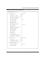
Contents
Preface . . . . . . . . . . . . . . . . . . . . . . . . . . . . . . . . . . . . . . . . . . . . . . . . . . . . . . 21
About this guide . . . . . . . . . . . . . . . . . . . . . . . . . . . . . . . . . . . . . . . . . . . . . . . . . . . . . . 21
Before you begin . . . . . . . . . . . . . . . . . . . . . . . . . . . . . . . . . . . . . . . . . . . . . . . . . . . . . 21
Text conventions . . . . . . . . . . . . . . . . . . . . . . . . . . . . . . . . . . . . . . . . . . . . . . . . . . . . . 22
Related publications . . . . . . . . . . . . . . . . . . . . . . . . . . . . . . . . . . . . . . . . . . . . . . . . . . . 23
How to get help . . . . . . . . . . . . . . . . . . . . . . . . . . . . . . . . . . . . . . . . . . . . . . . . . . . . . . 24
Chapter 1
CLI Basics. . . . . . . . . . . . . . . . . . . . . . . . . . . . . . . . . . . . . . . . . . . . . . . . . . . . 25
Stacking compatibility . . . . . . . . . . . . . . . . . . . . . . . . . . . . . . . . . . . . . . . . . . . . . . . . . . 26
Software version 2.0 compatibility with BayStack 450 switches . . . . . . . . . . . . . . . . . 27
New features . . . . . . . . . . . . . . . . . . . . . . . . . . . . . . . . . . . . . . . . . . . . . . . . . . . . . . . . 28
CLI command modes . . . . . . . . . . . . . . . . . . . . . . . . . . . . . . . . . . . . . . . . . . . . . . . . . . 29
Port numbering . . . . . . . . . . . . . . . . . . . . . . . . . . . . . . . . . . . . . . . . . . . . . . . . . . . . . . . 32
Port numbering in standalone mode . . . . . . . . . . . . . . . . . . . . . . . . . . . . . . . . . . . 32
Port numbering in stacked mode . . . . . . . . . . . . . . . . . . . . . . . . . . . . . . . . . . . . . . 33
IP notation . . . . . . . . . . . . . . . . . . . . . . . . . . . . . . . . . . . . . . . . . . . . . . . . . . . . . . . . . . 34
Accessing the CLI . . . . . . . . . . . . . . . . . . . . . . . . . . . . . . . . . . . . . . . . . . . . . . . . . . . . 35
Setting the CLI password . . . . . . . . . . . . . . . . . . . . . . . . . . . . . . . . . . . . . . . . . . . . . . . 38
cli password command . . . . . . . . . . . . . . . . . . . . . . . . . . . . . . . . . . . . . . . . . . . . . 38
Getting help . . . . . . . . . . . . . . . . . . . . . . . . . . . . . . . . . . . . . . . . . . . . . . . . . . . . . . . . . 39
Basic navigation . . . . . . . . . . . . . . . . . . . . . . . . . . . . . . . . . . . . . . . . . . . . . . . . . . . . . . 39
General navigation commands . . . . . . . . . . . . . . . . . . . . . . . . . . . . . . . . . . . . . . . 40
Keystroke navigation . . . . . . . . . . . . . . . . . . . . . . . . . . . . . . . . . . . . . . . . . . . . . . . 41
help command . . . . . . . . . . . . . . . . . . . . . . . . . . . . . . . . . . . . . . . . . . . . . . . . . . . . 42
no command . . . . . . . . . . . . . . . . . . . . . . . . . . . . . . . . . . . . . . . . . . . . . . . . . . . . . 42
default command . . . . . . . . . . . . . . . . . . . . . . . . . . . . . . . . . . . . . . . . . . . . . . . . . . 43
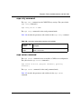
logout command . . . . . . . . . . . . . . . . . . . . . . . . . . . . . . . . . . . . . . . . . . . . . . . . . . 43
Reference for the Business Policy Switch 2000 Command Line Interface
8
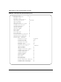
Contents
enable command . . . . . . . . . . . . . . . . . . . . . . . . . . . . . . . . . . . . . . . . . . . . . . . . . . 43
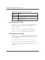
configure command . . . . . . . . . . . . . . . . . . . . . . . . . . . . . . . . . . . . . . . . . . . . . . . . 44
interface command . . . . . . . . . . . . . . . . . . . . . . . . . . . . . . . . . . . . . . . . . . . . . . . . 44
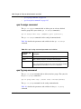
disable command . . . . . . . . . . . . . . . . . . . . . . . . . . . . . . . . . . . . . . . . . . . . . . . . . 45
end command . . . . . . . . . . . . . . . . . . . . . . . . . . . . . . . . . . . . . . . . . . . . . . . . . . . . 45
exit command . . . . . . . . . . . . . . . . . . . . . . . . . . . . . . . . . . . . . . . . . . . . . . . . . . . . 45
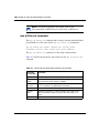
Managing basic system information . . . . . . . . . . . . . . . . . . . . . . . . . . . . . . . . . . . . . . . 46
show sys-info command . . . . . . . . . . . . . . . . . . . . . . . . . . . . . . . . . . . . . . . . . . . . 46
show cpu-utilization command . . . . . . . . . . . . . . . . . . . . . . . . . . . . . . . . . . . . . . . 47
show memory-utilization command . . . . . . . . . . . . . . . . . . . . . . . . . . . . . . . . . . . . 48
show stack-info command . . . . . . . . . . . . . . . . . . . . . . . . . . . . . . . . . . . . . . . . . . . 49
renumber unit command . . . . . . . . . . . . . . . . . . . . . . . . . . . . . . . . . . . . . . . . . . . . 49
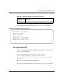
Managing MAC address forwarding database table . . . . . . . . . . . . . . . . . . . . . . . . . . 50
show mac-address-table command . . . . . . . . . . . . . . . . . . . . . . . . . . . . . . . . . . . . 50
mac-address-table aging-time command . . . . . . . . . . . . . . . . . . . . . . . . . . . . . . . 52
default mac-address-table aging-time command . . . . . . . . . . . . . . . . . . . . . . . . . 53
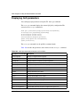
Displaying and setting stack operational mode . . . . . . . . . . . . . . . . . . . . . . . . . . . . . . 53
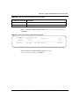
show stack-oper-mode command . . . . . . . . . . . . . . . . . . . . . . . . . . . . . . . . . . . . . 54
stack oper-mode command . . . . . . . . . . . . . . . . . . . . . . . . . . . . . . . . . . . . . . . . . . 54
Chapter 2
General CLI commands . . . . . . . . . . . . . . . . . . . . . . . . . . . . . . . . . . . . . . . . . 57
Setting the terminal . . . . . . . . . . . . . . . . . . . . . . . . . . . . . . . . . . . . . . . . . . . . . . . . . . . 58
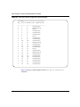
show terminal command . . . . . . . . . . . . . . . . . . . . . . . . . . . . . . . . . . . . . . . . . . . . 58
default terminal command . . . . . . . . . . . . . . . . . . . . . . . . . . . . . . . . . . . . . . . . . . . 58
terminal command . . . . . . . . . . . . . . . . . . . . . . . . . . . . . . . . . . . . . . . . . . . . . . . . . 59
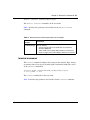
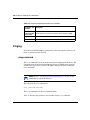
Pinging . . . . . . . . . . . . . . . . . . . . . . . . . . . . . . . . . . . . . . . . . . . . . . . . . . . . . . . . . . . . . 60
ping command . . . . . . . . . . . . . . . . . . . . . . . . . . . . . . . . . . . . . . . . . . . . . . . . . . . . 60
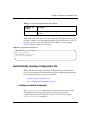
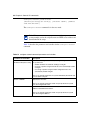
Automatically loading configuration file . . . . . . . . . . . . . . . . . . . . . . . . . . . . . . . . . . . . 61
configure network command . . . . . . . . . . . . . . . . . . . . . . . . . . . . . . . . . . . . . . . . . 61
show config-network command . . . . . . . . . . . . . . . . . . . . . . . . . . . . . . . . . . . . . . . 63
Assigning and clearing IP addresses . . . . . . . . . . . . . . . . . . . . . . . . . . . . . . . . . . . . . . 63
ip address command . . . . . . . . . . . . . . . . . . . . . . . . . . . . . . . . . . . . . . . . . . . . . . . 64
no ip address command . . . . . . . . . . . . . . . . . . . . . . . . . . . . . . . . . . . . . . . . . . . . 65
ip default-gateway command . . . . . . . . . . . . . . . . . . . . . . . . . . . . . . . . . . . . . . . . . 65
212160-B
Contents
9
no ip default-gateway command . . . . . . . . . . . . . . . . . . . . . . . . . . . . . . . . . . . . . . 66
show ip command . . . . . . . . . . . . . . . . . . . . . . . . . . . . . . . . . . . . . . . . . . . . . . . . . 67
Assigning and clearing IP addresses for specific units . . . . . . . . . . . . . . . . . . . . . . . . 68
ip address unit command . . . . . . . . . . . . . . . . . . . . . . . . . . . . . . . . . . . . . . . . . . . 68
no ip address unit command . . . . . . . . . . . . . . . . . . . . . . . . . . . . . . . . . . . . . . . . . 69
default ip address unit command . . . . . . . . . . . . . . . . . . . . . . . . . . . . . . . . . . . . . . 70
Setting Telnet access . . . . . . . . . . . . . . . . . . . . . . . . . . . . . . . . . . . . . . . . . . . . . . . . . . 71
show telnet-access command . . . . . . . . . . . . . . . . . . . . . . . . . . . . . . . . . . . . . . . . 71
telnet-access command . . . . . . . . . . . . . . . . . . . . . . . . . . . . . . . . . . . . . . . . . . . . . 72
no telnet-access command . . . . . . . . . . . . . . . . . . . . . . . . . . . . . . . . . . . . . . . . . . 73
default telnet-access command . . . . . . . . . . . . . . . . . . . . . . . . . . . . . . . . . . . . . . . 74
Setting server for Web-based management . . . . . . . . . . . . . . . . . . . . . . . . . . . . . . . . 74
web-server . . . . . . . . . . . . . . . . . . . . . . . . . . . . . . . . . . . . . . . . . . . . . . . . . . . . . . . 75
no web-server . . . . . . . . . . . . . . . . . . . . . . . . . . . . . . . . . . . . . . . . . . . . . . . . . . . . 75
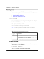
Setting boot parameters . . . . . . . . . . . . . . . . . . . . . . . . . . . . . . . . . . . . . . . . . . . . . . . . 75
boot command . . . . . . . . . . . . . . . . . . . . . . . . . . . . . . . . . . . . . . . . . . . . . . . . . . . . 76
ip bootp server command . . . . . . . . . . . . . . . . . . . . . . . . . . . . . . . . . . . . . . . . . . . 77
stack bootp-mac-addr-type command . . . . . . . . . . . . . . . . . . . . . . . . . . . . . . . . . . 77
no ip bootp server command . . . . . . . . . . . . . . . . . . . . . . . . . . . . . . . . . . . . . . . . . 78
default ip bootp server command . . . . . . . . . . . . . . . . . . . . . . . . . . . . . . . . . . . . . 78
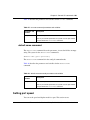
Setting TFTP parameters . . . . . . . . . . . . . . . . . . . . . . . . . . . . . . . . . . . . . . . . . . . . . . . 79
show tftp-server command . . . . . . . . . . . . . . . . . . . . . . . . . . . . . . . . . . . . . . . . . . 79
tftp-server command . . . . . . . . . . . . . . . . . . . . . . . . . . . . . . . . . . . . . . . . . . . . . . . 80
no tftp-server command . . . . . . . . . . . . . . . . . . . . . . . . . . . . . . . . . . . . . . . . . . . . . 80
copy config tftp command . . . . . . . . . . . . . . . . . . . . . . . . . . . . . . . . . . . . . . . . . . . 80
copy tftp config command . . . . . . . . . . . . . . . . . . . . . . . . . . . . . . . . . . . . . . . . . . . 81
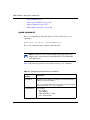
Upgrading software . . . . . . . . . . . . . . . . . . . . . . . . . . . . . . . . . . . . . . . . . . . . . . . . . . . 82
download command . . . . . . . . . . . . . . . . . . . . . . . . . . . . . . . . . . . . . . . . . . . . . . . 82
Observing LED indications . . . . . . . . . . . . . . . . . . . . . . . . . . . . . . . . . . . . . . . . . . 84
Upgrading software images . . . . . . . . . . . . . . . . . . . . . . . . . . . . . . . . . . . . . . . . . . 85
Displaying interfaces . . . . . . . . . . . . . . . . . . . . . . . . . . . . . . . . . . . . . . . . . . . . . . . . . . 88
show interfaces command . . . . . . . . . . . . . . . . . . . . . . . . . . . . . . . . . . . . . . . . . . . 88
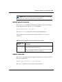
Setting SNMP parameters . . . . . . . . . . . . . . . . . . . . . . . . . . . . . . . . . . . . . . . . . . . . . . 90
snmp-server command . . . . . . . . . . . . . . . . . . . . . . . . . . . . . . . . . . . . . . . . . . . . . 91
no snmp-server command . . . . . . . . . . . . . . . . . . . . . . . . . . . . . . . . . . . . . . . . . . . 92
Reference for the Business Policy Switch 2000 Command Line Interface
10
Contents
snmp trap link-status command . . . . . . . . . . . . . . . . . . . . . . . . . . . . . . . . . . . . . . . 93
no snmp trap link-status command . . . . . . . . . . . . . . . . . . . . . . . . . . . . . . . . . . . . 93
default snmp trap link-status command . . . . . . . . . . . . . . . . . . . . . . . . . . . . . . . . . 94
Setting the system event log . . . . . . . . . . . . . . . . . . . . . . . . . . . . . . . . . . . . . . . . . . . . 95
show logging . . . . . . . . . . . . . . . . . . . . . . . . . . . . . . . . . . . . . . . . . . . . . . . . . . . . . 95
set logging . . . . . . . . . . . . . . . . . . . . . . . . . . . . . . . . . . . . . . . . . . . . . . . . . . . . . . . 96
no set logging . . . . . . . . . . . . . . . . . . . . . . . . . . . . . . . . . . . . . . . . . . . . . . . . . . . . 97
default set logging . . . . . . . . . . . . . . . . . . . . . . . . . . . . . . . . . . . . . . . . . . . . . . . . . 97
clear logging command . . . . . . . . . . . . . . . . . . . . . . . . . . . . . . . . . . . . . . . . . . . . . 97
Displaying port statistics . . . . . . . . . . . . . . . . . . . . . . . . . . . . . . . . . . . . . . . . . . . . . . . . 98
show port-statistics command . . . . . . . . . . . . . . . . . . . . . . . . . . . . . . . . . . . . . . . . 98
clear-stats command . . . . . . . . . . . . . . . . . . . . . . . . . . . . . . . . . . . . . . . . . . . . . . 100
Enabling or disabling a port . . . . . . . . . . . . . . . . . . . . . . . . . . . . . . . . . . . . . . . . . . . . 100
shutdown command . . . . . . . . . . . . . . . . . . . . . . . . . . . . . . . . . . . . . . . . . . . . . . 100
no shutdown command . . . . . . . . . . . . . . . . . . . . . . . . . . . . . . . . . . . . . . . . . . . . 101
Naming ports . . . . . . . . . . . . . . . . . . . . . . . . . . . . . . . . . . . . . . . . . . . . . . . . . . . . . . . 102
name command . . . . . . . . . . . . . . . . . . . . . . . . . . . . . . . . . . . . . . . . . . . . . . . . . . 102
no name command . . . . . . . . . . . . . . . . . . . . . . . . . . . . . . . . . . . . . . . . . . . . . . . 102
default name command . . . . . . . . . . . . . . . . . . . . . . . . . . . . . . . . . . . . . . . . . . . . 103
Setting port speed . . . . . . . . . . . . . . . . . . . . . . . . . . . . . . . . . . . . . . . . . . . . . . . . . . . 103
speed command . . . . . . . . . . . . . . . . . . . . . . . . . . . . . . . . . . . . . . . . . . . . . . . . . 104
default speed command . . . . . . . . . . . . . . . . . . . . . . . . . . . . . . . . . . . . . . . . . . . 105
duplex command . . . . . . . . . . . . . . . . . . . . . . . . . . . . . . . . . . . . . . . . . . . . . . . . . 105
default duplex command . . . . . . . . . . . . . . . . . . . . . . . . . . . . . . . . . . . . . . . . . . . 106
Enabling Autopology . . . . . . . . . . . . . . . . . . . . . . . . . . . . . . . . . . . . . . . . . . . . . . . . . 107
autotopology command . . . . . . . . . . . . . . . . . . . . . . . . . . . . . . . . . . . . . . . . . . . . 108
no autotopology command . . . . . . . . . . . . . . . . . . . . . . . . . . . . . . . . . . . . . . . . . 108
default autotopology command . . . . . . . . . . . . . . . . . . . . . . . . . . . . . . . . . . . . . . 108
Enabling flow control . . . . . . . . . . . . . . . . . . . . . . . . . . . . . . . . . . . . . . . . . . . . . . . . . 109
flowcontrol command . . . . . . . . . . . . . . . . . . . . . . . . . . . . . . . . . . . . . . . . . . . . . . 109
no flowcontrol command . . . . . . . . . . . . . . . . . . . . . . . . . . . . . . . . . . . . . . . . . . . 110
default flowcontrol command . . . . . . . . . . . . . . . . . . . . . . . . . . . . . . . . . . . . . . . . 110
Enabling rate-limiting . . . . . . . . . . . . . . . . . . . . . . . . . . . . . . . . . . . . . . . . . . . . . . . . . 111
show rate-limit command . . . . . . . . . . . . . . . . . . . . . . . . . . . . . . . . . . . . . . . . . . . 111
rate-limit command . . . . . . . . . . . . . . . . . . . . . . . . . . . . . . . . . . . . . . . . . . . . . . . 112
212160-B
Contents
11
no rate-limit command . . . . . . . . . . . . . . . . . . . . . . . . . . . . . . . . . . . . . . . . . . . . . 113
default rate-limit command . . . . . . . . . . . . . . . . . . . . . . . . . . . . . . . . . . . . . . . . . 114
Chapter 3
Security . . . . . . . . . . . . . . . . . . . . . . . . . . . . . . . . . . . . . . . . . . . . . . . . . . . . . 115
Using the IP manager list . . . . . . . . . . . . . . . . . . . . . . . . . . . . . . . . . . . . . . . . . . . . . . 115
show ipmgr command . . . . . . . . . . . . . . . . . . . . . . . . . . . . . . . . . . . . . . . . . . . . . 116
ipmgr command for management system . . . . . . . . . . . . . . . . . . . . . . . . . . . . . . 117
no ipmgr command for management system . . . . . . . . . . . . . . . . . . . . . . . . . . . 118
ipmgr command for source IP address . . . . . . . . . . . . . . . . . . . . . . . . . . . . . . . . 119
no ipmgr command for source IP address . . . . . . . . . . . . . . . . . . . . . . . . . . . . . . 119
Using MAC address security . . . . . . . . . . . . . . . . . . . . . . . . . . . . . . . . . . . . . . . . . . . 120
show mac-security command . . . . . . . . . . . . . . . . . . . . . . . . . . . . . . . . . . . . . . . 120
show mac-security mac-da-filter command . . . . . . . . . . . . . . . . . . . . . . . . . . . . . 121
mac-security command . . . . . . . . . . . . . . . . . . . . . . . . . . . . . . . . . . . . . . . . . . . . 122
mac-security mac-address-table address command . . . . . . . . . . . . . . . . . . . . . . 123
mac-security security-list command . . . . . . . . . . . . . . . . . . . . . . . . . . . . . . . . . . 124
no mac-security command . . . . . . . . . . . . . . . . . . . . . . . . . . . . . . . . . . . . . . . . . 125
no mac-security mac-address-table command . . . . . . . . . . . . . . . . . . . . . . . . . . 125
no mac-security security-list command . . . . . . . . . . . . . . . . . . . . . . . . . . . . . . . . 126
mac-security command for specific ports . . . . . . . . . . . . . . . . . . . . . . . . . . . . . . 126
mac-security mac-da-filter command . . . . . . . . . . . . . . . . . . . . . . . . . . . . . . . . . 127
Using EAPOL-based security . . . . . . . . . . . . . . . . . . . . . . . . . . . . . . . . . . . . . . . . . . . 128
show eapol command . . . . . . . . . . . . . . . . . . . . . . . . . . . . . . . . . . . . . . . . . . . . . 128
eapol command . . . . . . . . . . . . . . . . . . . . . . . . . . . . . . . . . . . . . . . . . . . . . . . . . . 129
eapol command for modifying parameters . . . . . . . . . . . . . . . . . . . . . . . . . . . . . 129
Using RADIUS authentication . . . . . . . . . . . . . . . . . . . . . . . . . . . . . . . . . . . . . . . . . . 131
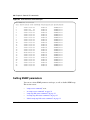
show radius-server command . . . . . . . . . . . . . . . . . . . . . . . . . . . . . . . . . . . . . . . 131
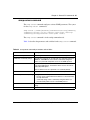
radius-server command . . . . . . . . . . . . . . . . . . . . . . . . . . . . . . . . . . . . . . . . . . . . 132
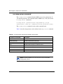
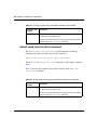
no radius-server command . . . . . . . . . . . . . . . . . . . . . . . . . . . . . . . . . . . . . . . . . 133
Chapter 4
Spanning Tree, MLT, and Port-Mirroring . . . . . . . . . . . . . . . . . . . . . . . . . . 135
Using spanning tree . . . . . . . . . . . . . . . . . . . . . . . . . . . . . . . . . . . . . . . . . . . . . . . . . . 135
show spanning-tree command . . . . . . . . . . . . . . . . . . . . . . . . . . . . . . . . . . . . . . 136
Reference for the Business Policy Switch 2000 Command Line Interface
12
Contents
spanning-tree stp create command by STG . . . . . . . . . . . . . . . . . . . . . . . . . . . . 139
spanning-tree stp delete command by STG . . . . . . . . . . . . . . . . . . . . . . . . . . . . 140
spanning-tree stp enable command by STG . . . . . . . . . . . . . . . . . . . . . . . . . . . . 140
spanning-tree stp disable command by STG . . . . . . . . . . . . . . . . . . . . . . . . . . . 141
spanning-tree command by STG . . . . . . . . . . . . . . . . . . . . . . . . . . . . . . . . . . . . . 142
default spanning-tree command by STG . . . . . . . . . . . . . . . . . . . . . . . . . . . . . . . 143
spanning-tree add-vlan command . . . . . . . . . . . . . . . . . . . . . . . . . . . . . . . . . . . . 143
spanning-tree remove-vlan command . . . . . . . . . . . . . . . . . . . . . . . . . . . . . . . . . 144
spanning-tree command by port . . . . . . . . . . . . . . . . . . . . . . . . . . . . . . . . . . . . . 145
default spanning-tree command by port . . . . . . . . . . . . . . . . . . . . . . . . . . . . . . . 146
no spanning-tree command by port . . . . . . . . . . . . . . . . . . . . . . . . . . . . . . . . . . . 147
Using MLT . . . . . . . . . . . . . . . . . . . . . . . . . . . . . . . . . . . . . . . . . . . . . . . . . . . . . . . . . 148
show mlt command . . . . . . . . . . . . . . . . . . . . . . . . . . . . . . . . . . . . . . . . . . . . . . . 148
mlt command . . . . . . . . . . . . . . . . . . . . . . . . . . . . . . . . . . . . . . . . . . . . . . . . . . . . 149
no mlt command . . . . . . . . . . . . . . . . . . . . . . . . . . . . . . . . . . . . . . . . . . . . . . . . . 150
Using port-mirroring . . . . . . . . . . . . . . . . . . . . . . . . . . . . . . . . . . . . . . . . . . . . . . . . . . 151
show port-mirroring command . . . . . . . . . . . . . . . . . . . . . . . . . . . . . . . . . . . . . . . 151
port-mirroring command . . . . . . . . . . . . . . . . . . . . . . . . . . . . . . . . . . . . . . . . . . . 151
no port-mirroring command . . . . . . . . . . . . . . . . . . . . . . . . . . . . . . . . . . . . . . . . . 153
Chapter 5
VLANs and IGMP . . . . . . . . . . . . . . . . . . . . . . . . . . . . . . . . . . . . . . . . . . . . . 155
Increased VLAN support . . . . . . . . . . . . . . . . . . . . . . . . . . . . . . . . . . . . . . . . . . . . . . 155
Configuring and displaying VLANs . . . . . . . . . . . . . . . . . . . . . . . . . . . . . . . . . . . . . . . 156
show vlan interface info command . . . . . . . . . . . . . . . . . . . . . . . . . . . . . . . . . . . 157
show vlan interface vids command . . . . . . . . . . . . . . . . . . . . . . . . . . . . . . . . . . . 158
vlan mgmt command . . . . . . . . . . . . . . . . . . . . . . . . . . . . . . . . . . . . . . . . . . . . . . 159
default vlan mgmt command . . . . . . . . . . . . . . . . . . . . . . . . . . . . . . . . . . . . . . . . 160
vlan create command . . . . . . . . . . . . . . . . . . . . . . . . . . . . . . . . . . . . . . . . . . . . . 160
vlan delete command . . . . . . . . . . . . . . . . . . . . . . . . . . . . . . . . . . . . . . . . . . . . . 162
no vlan command . . . . . . . . . . . . . . . . . . . . . . . . . . . . . . . . . . . . . . . . . . . . . . . . 163
vlan name command . . . . . . . . . . . . . . . . . . . . . . . . . . . . . . . . . . . . . . . . . . . . . . 163
auto-pvid command . . . . . . . . . . . . . . . . . . . . . . . . . . . . . . . . . . . . . . . . . . . . . . . 164
no auto-pvid command . . . . . . . . . . . . . . . . . . . . . . . . . . . . . . . . . . . . . . . . . . . . 164
vlan ports command . . . . . . . . . . . . . . . . . . . . . . . . . . . . . . . . . . . . . . . . . . . . . . 165
212160-B
Contents
13
vlan members command . . . . . . . . . . . . . . . . . . . . . . . . . . . . . . . . . . . . . . . . . . . 166
show vlan mac-address command . . . . . . . . . . . . . . . . . . . . . . . . . . . . . . . . . . . 166
vlan mac-address command . . . . . . . . . . . . . . . . . . . . . . . . . . . . . . . . . . . . . . . . 167
no vlan mac-address command . . . . . . . . . . . . . . . . . . . . . . . . . . . . . . . . . . . . . 168
Displaying multicast membership . . . . . . . . . . . . . . . . . . . . . . . . . . . . . . . . . . . . . . . . 168
show vlan multicast membership command . . . . . . . . . . . . . . . . . . . . . . . . . . . . 169
Using IGMP snooping . . . . . . . . . . . . . . . . . . . . . . . . . . . . . . . . . . . . . . . . . . . . . . . . 170
show vlan igmp command . . . . . . . . . . . . . . . . . . . . . . . . . . . . . . . . . . . . . . . . . . 170
vlan igmp command . . . . . . . . . . . . . . . . . . . . . . . . . . . . . . . . . . . . . . . . . . . . . . 171
default vlan igmp command . . . . . . . . . . . . . . . . . . . . . . . . . . . . . . . . . . . . . . . . . 172
Chapter 6
Policy-enabled networks and QoS . . . . . . . . . . . . . . . . . . . . . . . . . . . . . . . 173
Displaying QoS parameters . . . . . . . . . . . . . . . . . . . . . . . . . . . . . . . . . . . . . . . . . . . . 174
Resetting . . . . . . . . . . . . . . . . . . . . . . . . . . . . . . . . . . . . . . . . . . . . . . . . . . . . . . . . . . 185
qosagent reset-default command . . . . . . . . . . . . . . . . . . . . . . . . . . . . . . . . . . . . 185
Configuring COPS . . . . . . . . . . . . . . . . . . . . . . . . . . . . . . . . . . . . . . . . . . . . . . . . . . . 186
qosagent server-control command . . . . . . . . . . . . . . . . . . . . . . . . . . . . . . . . . . . 186
show cops retry command . . . . . . . . . . . . . . . . . . . . . . . . . . . . . . . . . . . . . . . . . . 187
show cops server command . . . . . . . . . . . . . . . . . . . . . . . . . . . . . . . . . . . . . . . . 187
show cops stats command . . . . . . . . . . . . . . . . . . . . . . . . . . . . . . . . . . . . . . . . . 188
cops retry command . . . . . . . . . . . . . . . . . . . . . . . . . . . . . . . . . . . . . . . . . . . . . . 191
cops server command . . . . . . . . . . . . . . . . . . . . . . . . . . . . . . . . . . . . . . . . . . . . . 191
default cops retry command . . . . . . . . . . . . . . . . . . . . . . . . . . . . . . . . . . . . . . . . 192
default cops server command . . . . . . . . . . . . . . . . . . . . . . . . . . . . . . . . . . . . . . . 192
no cops server command . . . . . . . . . . . . . . . . . . . . . . . . . . . . . . . . . . . . . . . . . . 193
Configuring QoS interface groups . . . . . . . . . . . . . . . . . . . . . . . . . . . . . . . . . . . . . . . 193
qos if-assign command . . . . . . . . . . . . . . . . . . . . . . . . . . . . . . . . . . . . . . . . . . . . 194
qos if-group command . . . . . . . . . . . . . . . . . . . . . . . . . . . . . . . . . . . . . . . . . . . . . 194
qos if-assign-list command . . . . . . . . . . . . . . . . . . . . . . . . . . . . . . . . . . . . . . . . . 195
Configuring DSCP and 802.1p and queue associations . . . . . . . . . . . . . . . . . . . . . . 196
qos egressmap command . . . . . . . . . . . . . . . . . . . . . . . . . . . . . . . . . . . . . . . . . . 196
qos ingressmap command . . . . . . . . . . . . . . . . . . . . . . . . . . . . . . . . . . . . . . . . . 197
qos queue-set-assignment command . . . . . . . . . . . . . . . . . . . . . . . . . . . . . . . . . 198
Configuring QoS filters and filter groups . . . . . . . . . . . . . . . . . . . . . . . . . . . . . . . . . . 198
Reference for the Business Policy Switch 2000 Command Line Interface
14
Contents
qos ip-filter command . . . . . . . . . . . . . . . . . . . . . . . . . . . . . . . . . . . . . . . . . . . . . 199
qos ip-filter-set command . . . . . . . . . . . . . . . . . . . . . . . . . . . . . . . . . . . . . . . . . . 200
qos l2-filter command . . . . . . . . . . . . . . . . . . . . . . . . . . . . . . . . . . . . . . . . . . . . . 201
qos l2-filter-set command . . . . . . . . . . . . . . . . . . . . . . . . . . . . . . . . . . . . . . . . . . 203
Configuring QoS actions . . . . . . . . . . . . . . . . . . . . . . . . . . . . . . . . . . . . . . . . . . . . . . 204
qos action command . . . . . . . . . . . . . . . . . . . . . . . . . . . . . . . . . . . . . . . . . . . . . . 204
Configuring QoS meters . . . . . . . . . . . . . . . . . . . . . . . . . . . . . . . . . . . . . . . . . . . . . . . 205
qos meter command . . . . . . . . . . . . . . . . . . . . . . . . . . . . . . . . . . . . . . . . . . . . . . 205
Configuring QoS shapers . . . . . . . . . . . . . . . . . . . . . . . . . . . . . . . . . . . . . . . . . . . . . . 206
qos shaper command . . . . . . . . . . . . . . . . . . . . . . . . . . . . . . . . . . . . . . . . . . . . . 207
Gathering QoS statistics . . . . . . . . . . . . . . . . . . . . . . . . . . . . . . . . . . . . . . . . . . . . . . 208
qosagent police-statistics command . . . . . . . . . . . . . . . . . . . . . . . . . . . . . . . . . . 208
Configuring QoS policies . . . . . . . . . . . . . . . . . . . . . . . . . . . . . . . . . . . . . . . . . . . . . . 209
qos policy command . . . . . . . . . . . . . . . . . . . . . . . . . . . . . . . . . . . . . . . . . . . . . . 209
Reordering packets . . . . . . . . . . . . . . . . . . . . . . . . . . . . . . . . . . . . . . . . . . . . . . . . . . 211
qosagent packet-reordering command . . . . . . . . . . . . . . . . . . . . . . . . . . . . . . . . 211
Appendix A
Command List . . . . . . . . . . . . . . . . . . . . . . . . . . . . . . . . . . . . . . . . . . . . . . . 213
Index . . . . . . . . . . . . . . . . . . . . . . . . . . . . . . . . . . . . . . . . . . . . . . . . . . . . . . . 225
212160-B
15
Figures
Figure 1
CLI command mode hierarchy . . . . . . . . . . . . . . . . . . . . . . . . . . . . . . . . . 30
Figure 2
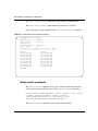
BPS 2000 banner . . . . . . . . . . . . . . . . . . . . . . . . . . . . . . . . . . . . . . . . . . . 36
Figure 3
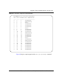
Main Menu for BPS 2000 console interface . . . . . . . . . . . . . . . . . . . . . . . 37
Figure 4
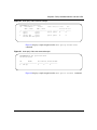
help command output in privExec mode . . . . . . . . . . . . . . . . . . . . . . . . . 42
Figure 5
show sys-info command output . . . . . . . . . . . . . . . . . . . . . . . . . . . . . . . . 47
Figure 6
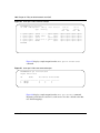
show cpu-utilization command output . . . . . . . . . . . . . . . . . . . . . . . . . . . 48
Figure 7
show memory-utilization command output . . . . . . . . . . . . . . . . . . . . . . . . 49
Figure 8
show stack-info command output . . . . . . . . . . . . . . . . . . . . . . . . . . . . . . . 49
Figure 9
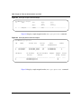
show mac-address-table command output . . . . . . . . . . . . . . . . . . . . . . . . 52
Figure 10
show stack-oper-mode command output . . . . . . . . . . . . . . . . . . . . . . . . . 54
Figure 11
show terminal command output . . . . . . . . . . . . . . . . . . . . . . . . . . . . . . . . 58
Figure 12
ping command responses . . . . . . . . . . . . . . . . . . . . . . . . . . . . . . . . . . . . 61
Figure 13
show config-network command . . . . . . . . . . . . . . . . . . . . . . . . . . . . . . . . 63
Figure 14
show ip command output . . . . . . . . . . . . . . . . . . . . . . . . . . . . . . . . . . . . . 68
Figure 15
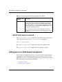
Telnet icon on Device Manager toolbar . . . . . . . . . . . . . . . . . . . . . . . . . . 71
Figure 16
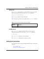
show telnet-access command output . . . . . . . . . . . . . . . . . . . . . . . . . . . . 72
Figure 17
show tftp-server command output . . . . . . . . . . . . . . . . . . . . . . . . . . . . . . 79
Figure 18
download message . . . . . . . . . . . . . . . . . . . . . . . . . . . . . . . . . . . . . . . . . . 84
Figure 19
show interfaces names command output . . . . . . . . . . . . . . . . . . . . . . . . . 89
Figure 20
show interfaces command output . . . . . . . . . . . . . . . . . . . . . . . . . . . . . . . 90
Figure 21
show logging command output . . . . . . . . . . . . . . . . . . . . . . . . . . . . . . . . . 96
Figure 22
show port-statistics command output . . . . . . . . . . . . . . . . . . . . . . . . . . . . 99
Figure 23
show rate-limit command output . . . . . . . . . . . . . . . . . . . . . . . . . . . . . . . 112
Figure 24
show ipmgr command output . . . . . . . . . . . . . . . . . . . . . . . . . . . . . . . . . 117
Figure 25
show mac-security command output . . . . . . . . . . . . . . . . . . . . . . . . . . . 121
Figure 26
show mac-security mac-da-filter command output . . . . . . . . . . . . . . . . . 122
Figure 27
show radius-server command output . . . . . . . . . . . . . . . . . . . . . . . . . . . 132
Figure 28
show spanning-tree command output by port . . . . . . . . . . . . . . . . . . . . 138
Figure 29
show spanning-tree command output for spanning tree group . . . . . . . 139
Reference for the Business Policy Switch 2000 Command Line Interface
16
Figures
Figure 30
show mlt command output . . . . . . . . . . . . . . . . . . . . . . . . . . . . . . . . . . . 149
Figure 31
show port-mirroring command output . . . . . . . . . . . . . . . . . . . . . . . . . . . 151
Figure 32
show vlan interface info output . . . . . . . . . . . . . . . . . . . . . . . . . . . . . . . . 158
Figure 33
show vlan interface vids output . . . . . . . . . . . . . . . . . . . . . . . . . . . . . . . 159
Figure 34
show vlan mac-address command output . . . . . . . . . . . . . . . . . . . . . . . 167
Figure 35
show vlan multicast membership command output . . . . . . . . . . . . . . . . 170
Figure 36
show vlan igmp command output . . . . . . . . . . . . . . . . . . . . . . . . . . . . . . 171
Figure 37
show qos interface-groups command output . . . . . . . . . . . . . . . . . . . . . 175
Figure 38
show qos interface-assignments command output . . . . . . . . . . . . . . . . . 176
Figure 39
show qos if-assign-lists command output . . . . . . . . . . . . . . . . . . . . . . . . 177
Figure 40
show qos egressmap command output . . . . . . . . . . . . . . . . . . . . . . . . . 178
Figure 41
show qos ingressmap command output . . . . . . . . . . . . . . . . . . . . . . . . . 178
Figure 42
show qos ip-filters command output . . . . . . . . . . . . . . . . . . . . . . . . . . . . 179
Figure 43
show qos ip-filter-sets command output . . . . . . . . . . . . . . . . . . . . . . . . . 179
Figure 44
show qos l2-filters command output . . . . . . . . . . . . . . . . . . . . . . . . . . . . 180
Figure 45
show qos l2-filter-sets command output . . . . . . . . . . . . . . . . . . . . . . . . . 180
Figure 46
show qos actions command output . . . . . . . . . . . . . . . . . . . . . . . . . . . . 181
Figure 47
show qos meters command output . . . . . . . . . . . . . . . . . . . . . . . . . . . . . 181
Figure 48
show qos shapers command output . . . . . . . . . . . . . . . . . . . . . . . . . . . . 182
Figure 49
show qos policies command output . . . . . . . . . . . . . . . . . . . . . . . . . . . . 182
Figure 50
show qos queue-sets command output . . . . . . . . . . . . . . . . . . . . . . . . . 183
Figure 51
show qos queue-set-assignments command output . . . . . . . . . . . . . . . 184
Figure 52
show qos agent command output . . . . . . . . . . . . . . . . . . . . . . . . . . . . . . 184
Figure 53
show qos statistics command output . . . . . . . . . . . . . . . . . . . . . . . . . . . 185
Figure 54
show cops retry command output . . . . . . . . . . . . . . . . . . . . . . . . . . . . . . 187
Figure 55
show cops server command output . . . . . . . . . . . . . . . . . . . . . . . . . . . . 188
Figure 56
show cops stats command output (1 of 2) . . . . . . . . . . . . . . . . . . . . . . . 189
Figure 57
show cops stats command output (2 of 2) . . . . . . . . . . . . . . . . . . . . . . . 190
212160-B
17
Tables
Table 1
Command mode prompts and entrance/exit commands . . . . . . . . . . . . . 31
Table 2
cli password command parameters and variables . . . . . . . . . . . . . . . . . . 39
Table 3
Keystroke navigation . . . . . . . . . . . . . . . . . . . . . . . . . . . . . . . . . . . . . . . . 41
Table 4
configure command parameters and variables . . . . . . . . . . . . . . . . . . . . . 44
Table 5
interface command parameters and variables . . . . . . . . . . . . . . . . . . . . . 45
Table 6
show mac-address-table command parameters and variables . . . . . . . . 51
Table 7
mac-address-table aging-time command parameters and variables . . . . 53
Table 8
stack oper-mode command parameters and variables . . . . . . . . . . . . . . . 55
Table 9
default terminal command parameters and variables . . . . . . . . . . . . . . . . 59
Table 10
terminal command parameters and variables . . . . . . . . . . . . . . . . . . . . . . 60
Table 11
ping command parameters and variables . . . . . . . . . . . . . . . . . . . . . . . . . 61
Table 12
configure network command parameters and variables . . . . . . . . . . . . . . 62
Table 13
ip address command parameters and variables . . . . . . . . . . . . . . . . . . . . 64
Table 14
no ip address command parameters and variables . . . . . . . . . . . . . . . . . 65
Table 15
ip default-gateway command parameters and variables . . . . . . . . . . . . . 66
Table 16
show ip command parameters and variables . . . . . . . . . . . . . . . . . . . . . . 67
Table 17
ip address unit command parameters and variables . . . . . . . . . . . . . . . . 69
Table 18
no ip address command parameters and variables . . . . . . . . . . . . . . . . . 69
Table 19
default ip address unit command parameters and variables . . . . . . . . . . 70
Table 20
telnet-access command parameters and variables . . . . . . . . . . . . . . . . . 73
Table 21
no telnet-access command parameters and variables . . . . . . . . . . . . . . . 74
Table 22
web-server command parameters and variables . . . . . . . . . . . . . . . . . . . 75
Table 23
boot command parameters and variables . . . . . . . . . . . . . . . . . . . . . . . . 76
Table 24
ip bootp server command parameters and variables . . . . . . . . . . . . . . . . 77
Table 25
stack boot-mac-addr-type command parameters and variables . . . . . . . . 78
Table 26
tftp-server command parameters and variables . . . . . . . . . . . . . . . . . . . . 80
Table 27
copy config tftp command parameters and variables . . . . . . . . . . . . . . . . 81
Table 28
copy tftp config command parameters and variables . . . . . . . . . . . . . . . . 81
Table 29
download command parameters and variables . . . . . . . . . . . . . . . . . . . . 83
Reference for the Business Policy Switch 2000 Command Line Interface
18
Tables
Table 30
LED Indications during the software download process . . . . . . . . . . . . . 84
Table 31
show interfaces command parameters and variables . . . . . . . . . . . . . . . 88
Table 32
snmp-server command parameters and variables . . . . . . . . . . . . . . . . . . 91
Table 33
no snmp-server command parameters and variables . . . . . . . . . . . . . . . 92
Table 34
snmp trap link-status command parameters and variables . . . . . . . . . . . 93
Table 35
no snmp trap link-status command parameters and variables . . . . . . . . . 94
Table 36
default snmp trap link-status command parameters and variables . . . . . 94
Table 37
show logging command parameters and variables . . . . . . . . . . . . . . . . . 95
Table 38
set logging command parameters and values . . . . . . . . . . . . . . . . . . . . . 96
Table 39
clear logging command parameters and values . . . . . . . . . . . . . . . . . . . . 98
Table 40
show port-statistics command parameters and variables . . . . . . . . . . . . . 98
Table 41
clear-stats command parameters and variables . . . . . . . . . . . . . . . . . . . 100
Table 42
shutdown command parameters and variables . . . . . . . . . . . . . . . . . . . 101
Table 43
no shutdown command parameters and variables . . . . . . . . . . . . . . . . . 101
Table 44
name command parameters and variables . . . . . . . . . . . . . . . . . . . . . . 102
Table 45
no name command parameters and variables . . . . . . . . . . . . . . . . . . . . 103
Table 46
default name command parameters and variables . . . . . . . . . . . . . . . . . 103
Table 47
speed command parameters and variables . . . . . . . . . . . . . . . . . . . . . . 104
Table 48
default speed command parameters and variables . . . . . . . . . . . . . . . . 105
Table 49
duplex command parameters and variables . . . . . . . . . . . . . . . . . . . . . . 106
Table 50
default duplex command parameters and variables . . . . . . . . . . . . . . . . 107
Table 51
flowcontrol command parameters and variables . . . . . . . . . . . . . . . . . . 109
Table 52
no flowcontrol command parameters and variables . . . . . . . . . . . . . . . . 110
Table 53
default flowcontrol command parameters and variables . . . . . . . . . . . . 111
Table 54
rate-limit command parameters and variables . . . . . . . . . . . . . . . . . . . . 113
Table 55
no rate-limit command parameters and variables . . . . . . . . . . . . . . . . . . 113
Table 56
default rate-limit command parameters and variables . . . . . . . . . . . . . . 114
Table 57
ipmgr command for system management parameters and variables . . . 118
Table 58
no ipmgr command for management system parameters and variables 118
Table 59
ipmgr command for source IP addresses parameters and variables . . . 119
Table 60
no ipmgr command for source IP addresses parameters and variables 120
Table 61
show mac-security command parameters and variables . . . . . . . . . . . . 121
Table 62
mac-security command parameters and values . . . . . . . . . . . . . . . . . . . 123
Table 63
mac-security mac-address-table address command parameters
and values . . . . . . . . . . . . . . . . . . . . . . . . . . . . . . . . . . . . . . . . . . . . . . . 124
212160-B
Tables
19
Table 64
mac-security security-list command parameters and values . . . . . . . . . 125
Table 65
no mac-security mac-address-table command parameters and values . 126
Table 66
no mac-security security-list command parameters and values . . . . . . . 126
Table 67
mac-security command for a single port parameters and variables . . . . 127
Table 68
mac-security mac-da-filter command parameters and values . . . . . . . . 128
Table 69
eapol command parameters and variables . . . . . . . . . . . . . . . . . . . . . . . 129
Table 70
eapol command for modifying parameters and variables . . . . . . . . . . . . 130
Table 71
radius-server command parameters and variables . . . . . . . . . . . . . . . . 132
Table 72
show spanning-tree command parameters and variables . . . . . . . . . . . 137
Table 73
spanning-tree stp create command parameters and variables . . . . . . . . 140
Table 74
spanning-tree stp delete command parameters and variables . . . . . . . . 140
Table 75
spanning-tree stp enable command parameters and variables . . . . . . . 141
Table 76
spanning-tree stp disable command parameters and variables . . . . . . . 141
Table 77
spanning-tree command by STG parameters and variables . . . . . . . . . 142
Table 78
default spanning-tree command by STG parameters and variables . . . 143
Table 79
spanning-tree add-vlan command parameters and variables . . . . . . . . . 144
Table 80
spanning-tree remove-vlan command parameters and variables . . . . . . 145
Table 81
spanning-tree command by port parameters and variables . . . . . . . . . . 146
Table 82
default spanning-tree command by port parameters and variables . . . . 147
Table 83
no spanning-tree command by port parameters and variables . . . . . . . 148
Table 84
show mlt command parameters and variables . . . . . . . . . . . . . . . . . . . . 149
Table 85
mlt command parameters and variables . . . . . . . . . . . . . . . . . . . . . . . . . 150
Table 86
no mlt command parameters and variables . . . . . . . . . . . . . . . . . . . . . . 150
Table 87
port-mirroring command parameters and variables . . . . . . . . . . . . . . . . 152
Table 88
show vlan command interface info parameters and variables . . . . . . . . 157
Table 89
show vlan command interface vids parameters and variables . . . . . . . . 159
Table 90
vlan mgmt command parameters and variables . . . . . . . . . . . . . . . . . . 160
Table 91
vlan create command parameters and variables . . . . . . . . . . . . . . . . . . 161
Table 92
vlan delete command parameters and variables . . . . . . . . . . . . . . . . . . 163
Table 93
no vlan command parameters and variables . . . . . . . . . . . . . . . . . . . . . 163
Table 94
vlan name command parameters and variables . . . . . . . . . . . . . . . . . . 164
Table 95
vlan ports command parameters and variables . . . . . . . . . . . . . . . . . . . 165
Table 96
vlan members command parameters and variables . . . . . . . . . . . . . . . . 166
Table 97
show vlan mac-address command parameters and variables . . . . . . . . 167
Table 98
vlan mac-address command parameters and variables . . . . . . . . . . . . . 168
Reference for the Business Policy Switch 2000 Command Line Interface
20
Tables
Table 99
no vlan mac-address command parameters and variables . . . . . . . . . . 168
Table 100
show vlan multicast membership command parameters and variables . 169
Table 101
show igmp command parameters and variables . . . . . . . . . . . . . . . . . . 171
Table 102
vlan igmp command parameters and variables . . . . . . . . . . . . . . . . . . . 172
Table 103
default vlan igmp command parameters and variables . . . . . . . . . . . . . 172
Table 104
show qos command parameters and variables . . . . . . . . . . . . . . . . . . . 174
Table 105
qosagent server-control command parameters and variables . . . . . . . . 186
Table 106
cops retry command parameters and variables . . . . . . . . . . . . . . . . . . . 191
Table 107
cops server command parameters and variables . . . . . . . . . . . . . . . . . . 192
Table 108
default cops server command parameters and variables . . . . . . . . . . . . 193
Table 109
no cops server command parameters and variables . . . . . . . . . . . . . . . 193
Table 110
qos if-assign command parameters and variables . . . . . . . . . . . . . . . . . 194
Table 111
qos if-group command parameters and variables . . . . . . . . . . . . . . . . . 195
Table 112
qos if-assign-list command parameters and variables . . . . . . . . . . . . . . 195
Table 113
qos egressmap command parameters and variables . . . . . . . . . . . . . . . 197
Table 114
qos ingressmap command parameters and variables . . . . . . . . . . . . . . 197
Table 115
qos queue-set-assignment command parameters and variables . . . . . . 198
Table 116
qos ip-filter command parameters and variables . . . . . . . . . . . . . . . . . . 199
Table 117
qos ip-filter-set command parameters and variables . . . . . . . . . . . . . . . 200
Table 118
qos l2-filter command parameters and variables . . . . . . . . . . . . . . . . . . 201
Table 119
qos l2-filter-set command parameters and variables . . . . . . . . . . . . . . . 203
Table 120
qos action command parameters and variables . . . . . . . . . . . . . . . . . . 204
Table 121
qos meter command parameters and variables
Table 122
qos shaper command parameters and variables . . . . . . . . . . . . . . . . . . 207
Table 123
qosagent police-statistics command parameters and variables . . . . . . . 208
. . . . . . . . . . . . . . . . . . 206
Table 124
qos policy command parameters and variables
Table 125
qosagent packet-reordering command parameters and variables . . . . . 211
Table 126
CLI command list . . . . . . . . . . . . . . . . . . . . . . . . . . . . . . . . . . . . . . . . . . 213
212160-B
. . . . . . . . . . . . . . . . . . 209
21
Preface
The Nortel Networks* Business Policy Switch 2000* command line interface
(CLI) is one tool used to configure and manage a Business Policy Switch 2000.
The CLI allows you to set up, configure, and manage your BPS 2000.
You can also use the Java* Device Manager graphical user interface (GUI), the
Web-based management system GUI, and the console interface (CI) menus to
configure and manage the switch. For more information on these management
systems, refer to Reference for the Business Policy Switch 2000 Management
Software Version 2.0, Using Web-based Management for the Business Policy
Switch 2000 Software Version 2.0, and Using the Business Policy Switch 2000
Software Version 2.0.
For general information on using and configuring the BPS 2000, refer to Using
the Business Policy Switch 2000 Software Version 2.0.
About this guide
This guide provides information about using the features and capabilities of the
CLI to manage switching operations in the BPS 2000, as well as a complete list of
CLI commands.
Before you begin
This guide is intended for network administrators with the following background:
•
•
•
Basic knowledge of networks, bridging, and IP
Familiarity with networking concepts and terminology
Basic knowledge of network topologies
Reference for the Business Policy Switch 2000 Command Line Interface
22 Preface
Before using this guide, you must complete the procedures discussed in the
Business Policy Switch 2000 Installation Instructions.
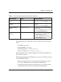
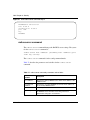
Text conventions
angle brackets (< >)
Indicate that you choose the text to enter based on the
description inside the brackets. Do not type the
brackets when entering the command.
Example: If the command syntax is
ip default-gateway <XXX.XXX.XXX.XXX>,
you enter
ip default-gateway 192.32.10.12
braces ({})
Indicate required elements in syntax descriptions
where there is more than one option. You must choose
only one of the options. Do not type the braces when
entering the command.
Example: If the command syntax is:
http-server {enable|disable}
the options for are enable or disable.
brackets ([ ])
Indicate optional elements in syntax descriptions. Do
not type the brackets when entering the command.
Example: If the command syntax is:
show ip [bootp],
you can enter either:
show ip or show ip bootp.
plain Courier
text
Indicates command syntax and system output.
Example:
TFTP Server IP Address:
212160-B
192.168.100.15
vertical line |
Separates choices for command keywords and
arguments. Enter only one of the choices. Do not type
the vertical line when entering the command.
Example: If the command syntax is:
cli password <serial|telnet>,
you must enter either cli password serial or
cli password telnet, but not both.
H.H.H.
Enter a MAC address in this format
(XXXX.XXXX.XXXX).
Preface 23
Related publications
For more information about managing or using Business Policy Switch 2000,
refer to the following publications:
•
•
•
•
•
•
•
•
•
•
•
•
•
•
•
•
•
Release Notes for the Business Policy Switch 2000 Software Version 2.0 (part
number 210676-F)
Installing the Business Policy Switch 2000 (part number 209319-A)
Using the Business Policy Switch 2000 Software Version 2.0
(part number 208700-C)
Getting Started with the Business Policy Switch 2000 Management Software
Operations (part number 209321-A)
Reference for the Business Policy Switch 2000 Management Software Version
2.0 (part number 209322-C)
Using Web-based Management for the Business Policy Switch 2000 Software
Version 2.0 (part number 209570-C)
Installing Media Dependent Adapters (MDAs) (part number 302403-H)
Installing Gigabit Interface Converters and Small Form Factor Pluggable
Interface Converters (part number 312865-B)
Installing and Administering Optivity Quick2Config 2.2
(part number 207809-B)
Using the Optivity Quick2Config 2.2 Client Software (part number 207810-B)
Configuring Business Policy Switches with Optivity Quick2Config 2.2
(part number 311208-A Rev 00)
Release Notes for Optivity Quick2Config 2.2 for Business Policy Switch 2000
2.2.1 (part number 310621-A)
Installing Optivity Policy Services (part number 306972-E Rev 00)
Managing Policy Information in Optivity Policy Services
(part number 306969-F Rev 00)
Release Notes for Optivity Policy Services Version 2.0.1
(part number 306975-F Rev 00)
Task Map - Installing Optivity Policy Services Product Family
(part number 306976-E Rev 00)
Known Anomalies for Optivity Policy Services Version 2.0
(part number 306974-E Rev 00)
Reference for the Business Policy Switch 2000 Command Line Interface
24 Preface
You can print selected technical manuals and release notes free, directly from the
Internet. Go to the www.nortelnetworks.com/documentation URL. (The product
family for the BPS 2000 is Data and Internet.) Find the product for which you
need documentation. Then locate the specific category and model or version for
your hardware or software product. Use Adobe* Acrobat Reader* to open the
manuals and release notes, search for the sections you need, and print them on
most standard printers. Go to Adobe Systems at the www.adobe.com URL to
download a free copy of the Adobe Acrobat Reader.
Additionally, you can obtain printed books from Fatbrain.com. Contact
Fatbrain.com to order a printed book at http://www1.fatbrain.com/documentation/
nortel.
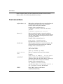
How to get help
If you purchased a service contract for your Nortel Networks product from a
distributor or authorized reseller, contact the technical support staff for that
distributor or reseller for assistance.
If you purchased a Nortel Networks service program, contact one of the following
Nortel Networks Technical Solutions Centers:
Technical Solutions Center
Telephone
Europe, Middle East, and Africa
(33) (4) 92-966-968
North America
(800) 4NORTEL or (800) 466-7835
Asia Pacific
(61) (2) 9927-8800
China
(800) 810-5000
Additional information about the Nortel Networks Technical Solutions Centers is
available from the www.nortelnetworks.com/help/contact/global URL.
An Express Routing Code (ERC) is available for many Nortel Networks products
and services. When you use an ERC, your call is routed to a technical support
person who specializes in supporting that product or service. To locate an ERC for
your product or service, go to the http://www130.nortelnetworks.com/cgi-bin/
eserv/common/essContactUs.jsp URL.
212160-B
Preface 25
Reference for the Business Policy Switch 2000 Command Line Interface
26 Preface
212160-B
25
Chapter 1
CLI Basics
You can manage the BPS 2000 with a number of tools. You can use either
graphical user interface (GUI), the Java Device Manager (DM) or the Web-based
management system. You can use the console interface (CI menus), or you can use
the command line interface (CLI). (For more information on using the DM, refer
to Reference for the Business Policy Switch 2000 Management Software Version
2.0. For more information on using the Web-based management system, refer to
Using Web-based Management for the Business Policy Switch 2000 Software
Version 2.0. For more information on using the CI menus, refer to Using the
Business Policy Switch 2000 Software Version 2.0.
The BPS 2000 command line interface (CLI) is a management tool that provides
methods for configuring, managing, and monitoring the operational functions of
the switch. You access the CLI through a direct connection to the switch console
port, or remotely using Telnet. For a complete, alphabetical list of CLI commands,
refer to Appendix A.
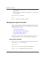
You can use the CLI interactively, or you can load and execute CLI “scripts.” CLI
scripts are loaded in one of the following ways:
•
•
•
By entering the configure network command.
By manually loading the script in the console menu.
By automatically loading the script at boot-up
This chapter discusses the following CLI topics:
•
•
•
•
•
“Stacking compatibility,” next
“Software version 2.0 compatibility with BayStack 450 switches” on page 27
“CLI command modes” on page 29
“Port numbering” on page 32
“IP notation” on page 34
Reference for the Business Policy Switch 2000 Command Line Interface
26 Chapter 1 CLI Basics
•
•
•
•
•
•
•
“Accessing the CLI” on page 35
“Setting the CLI password” on page 38
“Getting help” on page 39
“Basic navigation” on page 39
“Managing basic system information” on page 46
“Managing MAC address forwarding database table” on page 50
“Displaying and setting stack operational mode” on page 53
Stacking compatibility
You can stack the BPS 2000 up to 8 units high. There are two types of stacks:
•
•
Pure BPS 2000—This stack has only BPS 2000 switches. It is sometimes
referred to as a pure stack. The stack operational mode for this type of stack is
Pure BPS 2000 Mode.
Hybrid—This stack has a combination of BPS 2000 switches and BayStack*
450 and/or BayStack 410 switches. It is sometimes referred to as a mixed
stack. The stack operational mode for this type of stack is Hybrid Mode.
When you work with the BPS 2000 in standalone mode, you should ensure that
the stack operational mode shows Pure BPS 2000 Mode, and does not show
Hybrid Mode.
All BPS 2000 switches in the stack must be running the identical version of
software, and all the BayStack switches must be running the identical version of
software.
When you are working with a mixed stack, you must ensure that the
Interoperability Software Version Numbers (ISVN) are identical. That is, the
ISVN number for the BayStack 450 switch and BayStack 410 switch must have
the same ISVN as the BPS 2000. If the ISVNs are not the same, the stack does not
operate.
In sum, the stacking software compatibility requirements are as follows:
•
212160-B
Pure BPS 2000 stack—All units must be running the same software version.
Chapter 1 CLI Basics 27
•
•
Pure BayStack 450 stack—All units must be running the same software
version.
Hybrid stack:
— All BPS 2000 units must be running the same software version.
— All BayStack 410 units must be running the same software version.
— All BayStack 450 units must be running the same software version.
— All software versions must have the identical ISVN.
Refer to Appendix B of Using the Business Policy Switch 2000 Software Version
2.0 for complete information on interoperability and compatibility between the
BPS 2000 and BayStack switches.
Software version 2.0 compatibility with BayStack 450
switches
The BPS 2000 software version 2.0 is compatible with BayStack 450 software
version 4.1.
When you are using a local console to access the BPS 2000 software version 2.0
features with a Hybrid, or mixed, stack (BPS 2000 and BayStack 450 and 410
switches in the same stack), you must plug your local console into a BPS 2000
unit.
To find out which version of the BPS 2000 software is running, use the console
interface (CI) menus or the Web-based management system:
•
•
CI menus—From the main menu of the console, choose Systems
Characteristics menu. The software currently running is displayed in
sysDescr.
Web-based management system—Open the System Information page, which
is under Administration on the main menu. The software currently running is
displayed in the sysDescription field.
Reference for the Business Policy Switch 2000 Command Line Interface
28 Chapter 1 CLI Basics
You can use 256 port-, protocol-, and MAC SA-based VLANs for the stack with a
Pure BPS 2000 stack running software version 1.2. (The maximum number of
MAC SA-based VLANs available is 48). If you are working with a mixed, or
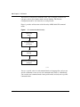
hybrid, stack, you can use 64 VLANs for the entire stack. When you change from
a Pure BPS 2000 Stack mode to a Hybrid Stack mode:
•
•
If you have up to 64 VLANs on the Pure BPS 2000 Stack, they will be
retained when you change to a Hybrid Stack.
If you have more than 64 VLANs on the Pure BPS 2000 Stack, you will lose
them all. The Hybrid Stack will return to the default VLAN configuration.
Also, a mixed, or hybrid, stack does not support multiple Spanning Tree Groups
(STG). You have a single instance of STG when working with a mixed stack.
•
•
If you have up to 64 VLANs on the Pure BPS 2000 Stack, they will be
retained when you change to a Hybrid Stack.
If you have more than 64 VLANs on the Pure BPS 2000 Stack, you will lose
them all. The Hybrid Stack will return to the default VLAN configuration.
Also, a mixed, or hybrid, stack does not support multiple Spanning Tree Groups
(STG). You have a single instance of STG when working with a mixed stack.
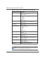
New features
The following new features that you can access through Web-based management
have been introduced to the BPS 2000 software since version 1.2:
•
212160-B
Introduced with software version 2.0
— Support for BPS 2000-1GT, BPS 2000-2GT, and BPS 2000-2GE MDAs
— Portlist command more inclusive (refer to “Port numbering” on page 32)
— Rate shaping for QoS networks (refer to Chapter 6)
— Expanded COPS commands (refer to Chapter 6)
— Port naming (refer to Chapter 2)
— MAC destination address (DA) filtering (refer to Chapter 3)
— IP for each unit in the stack (refer to Chapter 2)
Chapter 1 CLI Basics 29
— Configurable VID for tagged BPDU with multiple spanning tree groups
(refer to Chapter 4)
— Specifying multiple VLANs for QoS in a single layer 2 filter (refer to
Chapter 6)
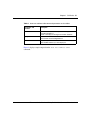
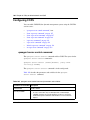
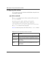
CLI command modes
Most CLI commands are available only under a certain command mode. The BPS
2000 has the following four command modes:
•
•
•
•
User EXEC
Privileged EXEC
Global Configuration
Interface Configuration
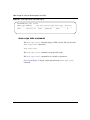
The User EXEC mode is the default mode; it is also referred to as exec. This
command mode is the initial mode of access upon first powering-up the BPS
2000. In this command mode, the user can access only a subset of the total CLI
commands; however, the commands in this mode are available while the user is in
any of the other four modes. The commands in this mode are those you would
generally need, such as ping and logout.
Commands in the Privileged EXEC mode are available to all other modes but the
User EXEC mode. The commands in this mode allow you to perform basic
switch-level management tasks, such as downloading the software image, setting
passwords, and booting the BPS 2000. The Privileged EXEC mode is also
referred to as privExec mode.
The last two command modes allow you to change the configuration of the BPS
2000. Changes made in these command modes are immediately applied to the
switch configuration and saved to NVRAM.
The Global Configuration commands allow you to set and display general
configurations for the switch, such as the IP address, SNMP parameters, the
Telnet access, and VLANs. The Global Configuration mode is also referred to as
config mode.
Reference for the Business Policy Switch 2000 Command Line Interface
30 Chapter 1 CLI Basics
The Interface Configuration commands allow you to configure parameters for
each port, such as speed, duplex mode, and rate-limiting. The Interface
Configuration mode is also referred to as config-if mode.
Figure 1 provides an illustration of the hierarchy of BPS 2000 CLI command
modes.
Figure 1 CLI command mode hierarchy
User Exec
(exec)
Privileged EXEC
(privExec)
Global Configuration
(config)
Interface Configuration
(config-if)
10194EA
You see a specific value for each command mode at the prompt line, and you use
specific commands to enter or exit each command mode (Table 1). Additionally,
you can only enter command modes from specific modes and only exit to specific
command modes.
212160-B
Chapter 1 CLI Basics 31
Table 1 Command mode prompts and entrance/exit commands
Command mode
Prompt
Enter/exit command
User EXEC
(exec)
BPS2000>
•
•
Privileged EXEC
(privExec)
BPS2000#
•
Default mode, automatically enter
logout or exit to quit CLI
enable to enter from User EXEC
mode
Global Configuration
(config)
BPS2000(config)#
•
logout or exit to quit CLI
•
configure to enter from Privileged
EXEC mode
logout to quit CLI; end or exit to
exit to Privileged EXEC mode
•
Interface Configuration
(config-if)
BPS2000(config-if)#
•
•
interface Fast Ethernet
{<portnum>|all} to enter from
Global Configuration mode
logout to quit CLI; end to exit to
Privileged EXEC mode; exit to exit to
Global Configuration mode
The prompt displays the switch name, BPS2000, and the current CLI command
mode:
•
•
•
•
User EXEC—BPS2000>
Privileged EXEC—BPS2000#
Global Configuration—BPS2000(config)#
Interface Configuration—BPS2000(config-if)#
Refer to Appendix A, for a complete, alphabetical list of all CLI commands and
where they are explained.
The initial command mode in CLI depends on your access level when you logged
into the BPS 2000 CI menus:
•
•
With no password protection, you enter the CLI in userExec mode, and use
the enable command to move to the privExec command mode.
If you logged into the CI menus with read-only access, you enter the CLI in
userExec mode and cannot access any other CLI command modes.
Reference for the Business Policy Switch 2000 Command Line Interface
32 Chapter 1 CLI Basics
•
If you logged into the CI menus with read-write access, you enter the CLI in
privExec mode and use the commands to move to the other command modes.
Port numbering
The BPS 2000 operates either in standalone mode or in stack mode. The BPS
2000 has 24 10/100 Mb/s ports on the front, as well as an uplink slot that allows
you to attach a media dependent adapter (MDA). The MDAs available for the
uplink can have up to 4 ports. Thus, you have a maximum of 28 ports on one BPS
2000.
In stack mode, the BPS 2000 operates either in Pure BPS 2000 Stack mode or in
Hybrid Stack mode. The Hybrid Stack mode is when you are working with a
combination of the BayStack 450 or 410 switches and BPS 2000 switches in one
stack. When you are working with a standalone BPS 2000, ensure that the
operational mode is set for Pure BPS 2000 Stack. (Refer to “show
stack-oper-mode command” on page 54 and “stack oper-mode command” on
page 54 for information on operational mode commands.)
B
Note: Beginning with software version 2.0, the variable portlist replaces
the use the variable portnum, or port-num, and all for ports. The CLI is
backward-compatible, so all commands in the previous release continue
to function properly.
The CLI uses the variable <portlist> when a command specifies one or more
ports for the command. The format of the variable <portlist> is different if
you are working with a standalone BPS 2000 or with a stack (either Pure BPS
2000 Stack or Hybrid Stack).
Port numbering in standalone mode
Ensure that the operational mode is set for the Pure BPS 2000 Stack mode when
you are working with a standalone BPS 2000.
In standalone mode, use the <portlist> variable in the following formats:
212160-B
Chapter 1 CLI Basics 33
•
•
•
•
•
A single port number—an integer between 1 through 28
— Example: 7 means port 7
A range of port numbers—a pair of port numbers between 1 and 28 separated
by a dash
— Example: 1-3 means ports 1, 2, and 3
— Example: 5-27 means all ports from port 5 through port 27
A list of port numbers and/or port ranges, separated by commas
— Example: 1,3,7 means ports 1, 3, and 7
— Example: 1-3,9-11 means ports 1, 2, 3, 9, 10, and 11
— Example: 1,3-5,9-11,15 means ports 1, 3, 4, 5, 9, 10, 11, and 15
none means no ports (not case-sensitive)
all means all the ports on the standalone BPS 2000, including any MDA
ports (not case-sensitive)
You can also use the unit/port convention discussed in “Port numbering in stacked
mode,” next, with a standalone BPS 2000 as long as the unit number is always 1.
Port numbering in stacked mode
In stacked mode, either Pure BPS 2000 Stack mode or Hybrid Stack Mode, use
the <portlist> variable to represent the number of the unit within the stack,
followed by a forward slash (/), followed by port number(s). The unit numbers
will always be integers between 1 and 8, and the port numbers will always be
integers between 1 and 28. You can also use none to indicate none of the ports in
the stack or all to indicate all of the ports in the stack.
In stacked mode, use the <portlist> variable in the following formats:
•
•
A single port number—an integer for the unit, followed by /, and an integer
for the port number
— Example: 1/7 means unit 1 port 7
— Example: 3/24 means unit 3, port 24
A range of port numbers—an integer for the unit, followed by /, and integers
for the port number between 1 and 28 separated by a dash
— Example: 1/1-3 means unit 1, ports 1, 2, and 3
— Example: 3/5-27 means unit 3, port 5 through port 27
Reference for the Business Policy Switch 2000 Command Line Interface
34 Chapter 1 CLI Basics
•
•
•
•
•
A unit with no ports specified—an integer for the unit, followed by /, and the
word none (not case-sensitive)
— 3/none means unit 3 with no ports
A unit with all ports specified—an integer for the unit, followed by /, and the
word all (not case-sensitive)
— 3/all means unit 3 with all ports
A list of port numbers, port ranges, and/or units with all ports or no ports—
using the unit/port format—separated by commas
— Example: 1/1,2/3,3/7 means unit 1 port 1; unit 2, port 3; and unit 3,
port 7
— Example: 1/1-3,3/9-11 means unit 1, ports 1, 2, 3; and unit 3, ports 9,
10, and 11
— Example: 1/1,4/3-5,5/9-11,7/15 means unit 1, port 1; unit 4, ports
3, 4, 5; unit 5, ports 9, 10, 11; and unit 7, port 15
— Example: 1/3,3/ALL,4/NONE means unit 1, port 3; unit 3, all ports; and
unit 4, no ports
none means no ports in the stack (not case-sensitive)
all means all the ports in the stack, including all MDA ports (not
case-sensitive)
To view the unit numbers in the stack, issue the show stack-info command
(“show stack-info command” on page 49). You must be in the Privileged EXEC
(privExec) mode to issue this command.
Refer to Using the Business Policy Switch 2000 Software Version 2.0 guide, for
more information on numbering units within the stack.
IP notation
You enter IP addresses and subnet masks in one of the following two ways in the
CLI. You can always enter an IP address in dotted decimal notation
(XXX.XXX.XXX.XXX), specifying both the IP address and the subnet mask in
dotted-decimal notation.
212160-B
Chapter 1 CLI Basics 35
Or, when you are specifying both an IP address and a netmask, you may
alternatively enter XXX.XXX.XXX.XXX/0-32, where XXX.XXX.XXX.XXX is
the IP address in dotted-decimal notation and the value 0-32 specifies the number
of bits starting from the left in the mask (for example, a value of 8 is 255.0.0.0).
Accessing the CLI
You access the CI menus using Telnet or a a direct connection to the switch from a
terminal or personal computer (PC). You can use any terminal or PC with a
terminal emulator as the CLI command station. Be sure the terminal has the
following features:
•
•
•
•
9600 bits per second (b/s), 8 data bits, 1 stop bit, no parity, no flow control
Serial terminal-emulation program such as Terminal or Hyperterm for
Windows NT* or Hyperterm for Windows* 95 or Windows 98
Cable and connector to match the male DTE connector (DB-9) on the BPS
2000 console port, with the DCE/DTE switch on the switch management
module set to DTE
VT100 Arrows checked in the Terminal Preferences window under Terminal
Options, and Block Cursor unchecked; VT-100/ANSI checked under
Emulation
To access the CLI:
1
When you access the BPS 2000, the banner appears (Figure 2).
Reference for the Business Policy Switch 2000 Command Line Interface
36 Chapter 1 CLI Basics
Figure 2 BPS 2000 banner
********************************************************
* Nortel Networks
* Copyright (c) 1996,2000,2001
* All Rights Reserved
* Business Policy Switch 2000
* Ver: HW:AB3
FW:1.1.0.1
SW:v2.0.0.00
ISVN:2
***************************************************************
Enter Ctrl-Y to begin.
2
212160-B
Press [Ctrl]+Y, and the Main Menu appears on the console screen (Figure 3)
with the top line highlighted.
Chapter 1 CLI Basics 37
Figure 3 Main Menu for BPS 2000 console interface
Business Policy Switch 2000 Main Menu
IP Configuration/Setup...
SNMP Configuration...
System Characteristics...
Switch Configuration...
Display Hardware Units...
Spanning Tree Configuration...
Applications Remote Access Setup...
TELNET Configuration...
Software Download...
Configuration File...
Display System Log
Reset
Reset to Default Settings
Command Line Interface
Logout
Use arrow keys to highlight option, press <Return> or <Enter> to
select option.
3
Using the Down Arrow key, scroll down to Command Line Interface, and
press [Enter]. The CLI cursor appears:
BPS2000>
The > sign at the end of the name of the switch indicates that the CLI opens in
User EXEC mode. Refer to “CLI command modes” on page 29, to select the
command mode you want to use (and are authorized to use).
Reference for the Business Policy Switch 2000 Command Line Interface
38 Chapter 1 CLI Basics
Setting the CLI password
You can set passwords using the cli password command for selected types of
access using the CLI, Telnet, or RADIUS security.
For more information on Telnet access, refer to Chapter 3. For more information
on using RADIUS security with the CLI, refer to Chapter 3.
cli password command
The cli password is in two forms and performs the following functions for
either the switch of the entire stack:
•
•
Changes the password for access through the serial console port and Telnet
Specifies changing the password for serial console port or Telnet access and
whether to authenticate password locally or with the RADIUS server
The syntax for the cli password commands are:
cli password {switch|stack} {ro|rw} <WORD> <WORD>
cli password {switch|stack} {serial|telnet}
{none|local|radius}
The cli password command is in the config command mode.
Table 2 describes the parameters and variables for the cli password command.
212160-B
Chapter 1 CLI Basics 39
Table 2 cli password command parameters and variables
Parameters and
variables
switch|stack
Description
Specifies you are modifying the settings on the switch or on the
stack.
Note: If you omit this parameter, the system modifies the
information for the current mode.
ro|rw
Specifies you are modifying the read-only (ro) password or the
read-write (rw) password.
<WORD>
<WORD>
Enter your username for the first variable, and your password for
the second variable.
serial|telnet
Specifies you are modifying the password for serial console
access or for Telnet access.
none|local|radius
Specifies the password you are modifying:
• none—disables the password
• local—use the locally defined password for serial console or
Telnet access
• radius—use RADIUS authentication for serial console or Telnet
access
Getting help
When you navigate through the CLI, online help is available at all levels. Entering
a portion of the command, space, and a question mark (?) at the prompt results in
a list of all options for that command.
Refer to “help command” on page 42 for more information about the specific
types of online help.
Basic navigation
This section discusses basic navigation around the CLI and between the command
modes. As you see, the CLI incorporates various shortcut commands and
keystrokes to simplify its use. The following topics are covered in this section:
Reference for the Business Policy Switch 2000 Command Line Interface
40 Chapter 1 CLI Basics
•
•
•
•
•
•
•
•
•
•
•
•
“General navigation commands,” next
“Keystroke navigation” on page 41
“help command” on page 42
“no command” on page 42
“default command” on page 43
“logout command” on page 43
“enable command” on page 43
“configure command” on page 44
“interface command” on page 44
“disable command” on page 45
“end command” on page 45
“exit command” on page 45
General navigation commands
When you enter ? at any point in the CLI session, the system retrieves help
information for whatever portion of the command you entered thus far. Refer to
“help command” on page 42 for more information.
The system records the last command in a CLI session. However, the last
command is not saved across reboots.
Add the word no to the beginning of most CLI configuration commands to clear
or remove the parameters of the actual command. For example, when you enter
the command ip stack address 192.32.154.126, you set the IP stack
address. However, when you enter no ip stack address, the system returns
the IP address to zero. Refer to Appendix A for an alphabetical list of no
commands.
Add the word default to the beginning of most CLI configuration commands
returns the parameters of the actual command to the factory default values. Refer
to Appendix A for an alphabetical list of default commands.
When you enter a portion of the command and the [Tab] key, the system finds the
first unambiguous match of a command and displays that command. For example,
if you enter down+[Tab], the system displays download.
212160-B
Chapter 1 CLI Basics 41
Keystroke navigation
You change the location of the cursor using the key combinations shown in
Table 3.
Table 3 Keystroke navigation
Key combination
Function
[Ctrl]+A
Start of line
[Ctrl]+B
Back 1 character
[Ctrl]+C
Abort command
[Ctrl]+D
Delete the character indicated by the cursor
[Ctrl]+E
End of line
[Ctrl]+F
Forward 1 character
[Ctrl]+H
Delete character left of cursor (Backspace key)
[Ctrl]+I &
Command/parameter completion
[Ctrl]+K & [Ctrl]+R
Redisplay line
[Ctrl]+N or [Down arrow]
Next history command
[Ctrl]+P or [Up arrow]
Previous history command
[Ctrl]+T
Transpose characters
[Ctrl]+U
Delete entire line
[Ctrl]+W
Delete word left of cursor
[Ctrl]+X
Delete all characters to left of cursor
[Ctrl]+z
Exit Global Configuration mode (to Privileged EXEC
mode)
?
Context-sensitive help
[Esc]+c & [Esc]+u
Capitalize character at cursor
[Esc]+l
Change character at cursor to lowercase
[Esc]+b
Move back 1 word
[Esc]+d
Delete 1 word to the right
[Esc]+f
Move 1 word forward
Reference for the Business Policy Switch 2000 Command Line Interface
42 Chapter 1 CLI Basics
help command
The help command is in all command modes and displays a brief message about
using the CLI help system. The syntax for the help command is:
help
The help command has no parameters or variables.
Figure 4 shows the output from the help command.
Figure 4 help command output in privExec mode
BPS2000#help
Help may be requested at any point in a command by entering
a question mark ’?’. If nothing matches, the help list will
be empty and you must backup until entering a ’?’ shows the
available options.
Two styles of help are provided:
1. Full help is available when you are ready to enter a command argument
(e.g. ’show ?’) and describes each possible argument.
2. Partial help is provided when an abbreviated argument is entered and you
want to know what arguments match the input (e.g. ’show pr?’.)
no command
The no command is always used as a prefix to a configuration command, and it
negates the action performed by that command. The effect of the no command is
to remove or to clear the configuration controlled by the specified command.
Various no commands are in the config and config-if command modes.
Refer to Appendix A for an alphabetical listing of all no commands.
Note: Not all configuration commands support the no prefix
command.
212160-B
Chapter 1 CLI Basics 43
default command
The default command is always used as a prefix to a configuration command,
and it restores the configuration parameters to default values. The default values
are specified by each command.
Refer to Appendix A for an alphabetical listing of all default commands.
Note: Not all commands support the default prefix command.
logout command
The logout command logs you out of the CLI session and returns you to the
Main Menu of the console interface (CI) menus (Figure 3). The syntax for the
logout command is:
logout
The logout command is in all command modes.
The logout command has no parameters or variables.
enable command
The enable command changes the command mode from User EXEC to privExec
mode. The syntax for the enable command is:
enable
The enable command is in the exec command mode.
The enable command has no parameters or variables.
Reference for the Business Policy Switch 2000 Command Line Interface
44 Chapter 1 CLI Basics
Note: You must have read-write access to the BPS 2000 switch to be
able to use the enable command.
configure command
The configure command moves you to the Global Configuration (config)
command mode and identifies the source for the configuration commands. The
syntax for the configure command is:
configure {terminal|network|memory}
The configure command is in the privExec command mode.
Table 4 describes the parameters and variables for the configure command.
Table 4 configure command parameters and variables
Parameters and
variables
Description
terminal|network| Specifies the source for the configuration commands for the BPS 2000:
memory
• terminal—allows you to enter config mode to enter configuration
commands
• network—allows you to set up parameters for auto-loading a script
at boot-up or for loading and executing a script immediately
• memory—not supported on BPS 2000
interface command
The interface command moves you to the Interface Configuration (config-if)
command mode. The syntax for the interface command is:
interface FastEthernet {<portlist>}
The interface command is in the config command mode.
212160-B
Chapter 1 CLI Basics 45
Table 5 describes the parameters and variables for the interface command.
Table 5 interface command parameters and variables
Parameters
and variables
Description
<portlist>
Specifies the portlist you want to be affected by all the commands
issued in the config-if command mode.
disable command
The disable command returns you to the User EXEC (exec) command mode.
The syntax for the disable command is:
disable
The disable command is in the privExec command mode.
The disable command has no parameters or variables.
end command
The end command moves you to the priv Exec mode from either the Global
Configuration (config) mode or the Interface Configuration (config-if) mode.
The syntax for the end command is:
end
The end command has no parameters or variables.
exit command
The exit command moves you around the command modes:
•
In User EXEC (exec) and Privileged EXEC (privExec) command modes,
exit allows you to quit the CLI session.
Reference for the Business Policy Switch 2000 Command Line Interface
46 Chapter 1 CLI Basics
•
•
In Global Configuration (config) mode, exit moves you back to the privExec
command mode.
In Interface Configuration (config-if) command mode, exit moves you back
to the config mode.
The syntax for the exit command is:
exit
The exit command has no parameters or variables.
Managing basic system information
This section shows you how to view basic system information, such as the current
software version and the stack mode; you can renumber the units within a stack.
The following topics are covered:
•
•
•
•
•
“show sys-info command,” next
“show cpu-utilization command” on page 47
“show memory-utilization command” on page 48
“show stack-info command” on page 49
“renumber unit command” on page 49
Refer to Using the Business Policy Switch 2000 Software Version 2.0, for more
information on the operation of the stack mode, including unit numbering.
show sys-info command
The show sys-info command displays the current system characteristics. The
syntax for the show sys-info command is:
show sys-info
The show sys-info command is in the privExec command mode.
The show sys-info command has no parameters or variables.
212160-B
Chapter 1 CLI Basics 47
Figure 5 displays sample output from the show sys-info command.
Figure 5 show sys-info command output
BPS2000#show sys-info
Operation Mode:
Switch
MAC Address:
01-6C-0F-8C-01-2E
Reset Count:
16
Last Reset Type: Power Cycle
Power Status:
Primary Power
Local MDA Type:
None
sysDescr:
Business Policy Switch 2000
HW:AB3
FW:1.1.0.1
SW:v2.0.0.01 ISVN:2
sysObjectID:
1.3.6.1.4.1.45.3.40.1
sysUpTime:
6 days, 11:14:22
sysServices:
3
sysContact:
Jane Doe
sysName:
Engineering
sysLocation:
sylvan6-2
To change the system contact, name, or location, refer to the snmp-server
command in Chapter 2.
show cpu-utilization command
The show cpu-utilization command displays the percentage of the CPU
utilized from system boot-up and in the last 10 seconds, 1 minute, 10, minutes, 60
minutes, and 24 hours. The syntax for the show cpu-utilization command
is:
show cpu-utilization
The show cpu-utilization command is in the privExec command mode.
The show cpu-utilization command has no parameters or variables.
Figure 6 displays sample output from the show cpu-utilization command.
Reference for the Business Policy Switch 2000 Command Line Interface
48 Chapter 1 CLI Basics
Figure 6 show cpu-utilization command output
BPS2000#show cpu-utilization
From System Boot-Up: 36 %
Last 10 Seconds:
38 %
Last 1 Minute:
37 %
Last 10 Minutes:
36 %
Last 60 Minutes:
36 %
Last 24 Hours:
show memory-utilization command
The show memory-utilization command displays the percentage of
available memory, as well as the lowest memory available at any time since the
last boot-up. The syntax for the show memory-utilization command is:
show memory-utilization
The show memory-utilization command is in the privExec command mode.
The show memory-utilization command has no parameters or variables.
Figure 6 displays sample output from the show memory-utilization
command.
212160-B
Chapter 1 CLI Basics 49
Figure 7 show memory-utilization command output
BPS2000#show memory-utilization
Available: 71 %
Low Mark:
68 %
show stack-info command
The show stack-info command displays the current stack information, which
includes unit numbers, MDA and cascade attachments, and software version for
all units. The syntax for the show stack-info command is:
show stack-info
The show stack-info command is in the privExec command mode.
The show stack-info command has no parameters or variables.
Figure 8 displays sample output from the show stack-info command.
Figure 8 show stack-info command output
BPS2000#show stack-info
Unit # Switch Model
MDA Model Cascade MDA SW Version
---------------------------------------------------------1
BPS 2000
None
None
v2.0.0.01
renumber unit command
The renumber unit command changes the unit number of each switch in the
stack. The syntax for the renumber unit command is:
renumber unit
The renumber unit command is in the config command mode.
Reference for the Business Policy Switch 2000 Command Line Interface
50 Chapter 1 CLI Basics
The renumber unit command has no parameters or variables.
Note: This command does not take effect until you reset the stack.
Managing MAC address forwarding database table
This section shows you how to view the contents of the MAC address forwarding
database table, as well as setting the age-out time for the addresses. The following
topics are covered:
•
•
•
“show mac-address-table command,” next
“mac-address-table aging-time command” on page 52
“default mac-address-table aging-time command” on page 53
show mac-address-table command
The show mac-address-table command displays the current contents of the
MAC address forwarding database table. The syntax for the show
mac-address-table command is:
show mac-address-table [vid <1-4094>] [aging-time] [address
<H.H.H>]
The show mac-address-table command is in the privExec command mode.
Table 6 describes the parameters and variables for the show
mac-address-table command.
212160-B
Chapter 1 CLI Basics 51
Table 6 show mac-address-table command parameters and variables
Parameters and
variables
Description
vid <1-4094>
Enter the number of the VLAN you want to display the
forwarding database of.
Default is to display the management VLAN’s database.
aging-time
Displays the time in seconds after which an unused entry is
removed from the forwarding database.
address <H.H.H>
Displays a specific MAC address if it exists in the database.
Enter the MAC address you want displayed.
Figure 9 displays sample output from the show mac-address-table
command.
Reference for the Business Policy Switch 2000 Command Line Interface
52 Chapter 1 CLI Basics
Figure 9 show mac-address-table command output
BPS2000#show mac-address-table
MAC Address
Port
MAC Address
----------------- ----- ----------------00-60-fd-f8-68-48 2/2
00-80-2d-8c-2e-3f
00-80-2d-8f-66-de 2/2
00-80-2d-ca-93-57
00-90-27-3a-b4-be 2/2
00-90-27-9c-6e-78 2/2
00-a0-c9-04-ed-52
00-a0-cc-39-bf-39 2/2
00-a0-cc-5a-eb-17 2/2
00-a0-cc-5b-b2-9c
00-a0-cc-65-57-a8 2/2
00-a0-cc-d0-bd-f0
00-a0-cc-d1-4c-f8 2/2
00-a0-cc-d1-75-48
00-a0-cc-d1-7a-24 2/2
00-b0-d0-3d-ea-7a 2/2
00-b0-d0-b7-8e-f9
00-c0-4f-0e-d4-21 2/2
00-c0-4f-0e-d8-ce
00-c0-4f-40-5a-4d 2/2
00-c0-4f-6a-b8-8f
00-c0-4f-6a-b8-a1 2/2
00-c0-4f-8e-1f-18
00-c0-4f-8e-20-45 2/2
00-d0-09-4f-bf-18
00-d0-09-5b-06-81 2/2
00-e0-7b-10-1c-0a
00-e0-7b-10-1c-0b 2/2
BPS2000#
Port
----2/2
2/2
2/2
2/2
2/2
2/2
2/2
2/2
2/2
2/2
2/2
mac-address-table aging-time command
The mac-address-table aging-time command sets the time that the switch
retains unseen MAC addresses. The syntax for the mac-address-table
aging-time command is:
mac-address-table aging-time <time>
The mac-address-table aging-time command is in the config command
mode.
Table 7 describes the parameters and variables for the mac-address-table
aging-time command.
212160-B
Chapter 1 CLI Basics 53
Table 7 mac-address-table aging-time command parameters and variables
Parameters
and
variables
time
Description
Enter the aging time in seconds that you want for MAC
addresses before they are flushed.
default mac-address-table aging-time command
The default mac-address-table aging-time command sets the time that
the switch retains unseen MAC addresses to 300 seconds. The syntax for the
default mac-address-table aging-time command is:
default mac-address aging-time
The default mac-address-table aging-time command is in the config
command mode.
The default mac-address-table aging-time command has no parameters
or variables.
Displaying and setting stack operational mode
This section shows you how to view and set the stack operational mode. The
following topics are covered:
•
•
“show stack-oper-mode command,” next
“stack oper-mode command” on page 54
Refer to Using the Business Policy Switch 2000 Software Version 2.0 for more
information on the stack operation, including features requiring specific
operational modes and adding switches to the stack.
Reference for the Business Policy Switch 2000 Command Line Interface
54 Chapter 1 CLI Basics
show stack-oper-mode command
The show stack-oper-mode command displays the current operational mode
of the stack and the mode set for the next switch reboot. The display shows either:
•
Pure BPS 2000 Stack
or
•
Hybrid Stack
The syntax for the show stack-oper-mode command is:
show stack-oper-mode
The show stack-oper-mode command is in the privExec command mode.
The show stack-oper-mode command has no parameters or variables.
Figure 10 displays sample output from the show stack-oper-mode command.
Figure 10 show stack-oper-mode command output
BPS2000#show stack-oper-mode
Current Operational Mode: Pure BPS 2000 Stack
Next Boot Operational Mode: Pure BPS 2000 Stack
stack oper-mode command
The stack oper-mode command allows you to set the stack operational mode,
which becomes active at the next reboot of the switch or stack. The syntax for the
stack oper-mode command is:
stack oper-mode {bps2000|hybrid}
The stack oper-mode command is in the config command mode.
Table 8 describes the parameters and variables for the stack oper-mode
command.
212160-B
Chapter 1 CLI Basics 55
Table 8 stack oper-mode command parameters and variables
Parameters and
variables
bps2000|hybrid
Description
Sets the stack operational mode for the next boot:
• bps2000—Pure BPS 2000 Stack mode. This means only
BPS 2000 switches either standalone or in a stack.
• hybrid—Hybrid Stack mode. This means a mixture of BPS
2000 and BayStack 450 or 410 switches in a stack.
Note: You must reboot the system for the stack operation mode you
entered in the CLI to take effect.
Reference for the Business Policy Switch 2000 Command Line Interface
56 Chapter 1 CLI Basics
212160-B
57
Chapter 2
General CLI commands
In the BPS 2000, the Command Line Interface (CLI) commands allows you to
display and modify the switch configuration while the switch is operating.
This chapter includes information about general switch maintenance, such as
setting up access parameters, upgrading the software, and setting the speed. This
chapter covers the following topics:
•
•
•
•
•
•
•
•
•
•
•
•
•
•
•
•
•
•
•
“Setting the terminal,” next
“Pinging” on page 60
“Assigning and clearing IP addresses” on page 63
“Assigning and clearing IP addresses for specific units” on page 68
“Setting Telnet access” on page 71
“Setting server for Web-based management” on page 74
“Setting boot parameters” on page 75
“Setting TFTP parameters” on page 79
“Upgrading software” on page 82
“Displaying interfaces” on page 88
“Setting SNMP parameters” on page 90
“Setting the system event log” on page 95
“Displaying port statistics” on page 98
“Enabling or disabling a port” on page 100
“Naming ports” on page 102
“Setting port speed” on page 103
“Enabling Autopology” on page 107
“Enabling flow control” on page 109
“Enabling rate-limiting” on page 111
Reference for the Business Policy Switch 2000 Command Line Interface
58 Chapter 2 General CLI commands
Setting the terminal
You can view the terminal settings, set them to default settings, or customize the
terminal settings.This sections covers:
•
•
•
“show terminal command,” next
“default terminal command” on page 58
“terminal command” on page 59
show terminal command
The show terminal command displays the current serial port information,
which includes connection speed, as well as the terminal width and length in
number of characters. The syntax for the show terminal command is:
show terminal
The show terminal command is in the exec command mode.
The show terminal command has no parameters or variables.
Figure 11 displays the output from the show terminal command.
Figure 11 show terminal command output
BPS2000#show terminal
Terminal speed: 9600
Terminal width: 79
Terminal length: 23
BPS2000#
default terminal command
The default terminal command configures default settings for the terminal.
These settings are transmit and receive speeds, terminal length, and terminal
width. The syntax for the default terminal command is:
212160-B
Chapter 2 General CLI commands 59
default terminal {speed|width|length}
The default terminal command is in the exec mode.
Table 9 describes the parameters and variables for the default terminal
command.
Table 9 default terminal command parameters and variables
Parameters and
variables
speed|width|length
Description
Sets the defaults
• speed—transmit and receive baud rates for the terminal;
default is 9600 baud
• width—width of the terminal display; default is 79 characters
• length—Length of the terminal display; default is 24 characters
terminal command
The terminal command configures the settings for the terminal. These settings
are transmit and receive speeds, terminal length, and terminal width. The syntax
of the terminal command is:
terminal speed {2400|4800|9600|19200|38400}|length
<1-132>|width <1-132>
The terminal command is in the exec mode.
Table 10 describes the parameters and variables for the terminal command.
Reference for the Business Policy Switch 2000 Command Line Interface
60 Chapter 2 General CLI commands
Table 10 terminal command parameters and variables
Parameters and
variables
Description
speed
Sets the transmit and receive baud rates for the terminal. You can
{2400|4800|9600| set the speed at one of the five options shown; default is 9600.
19200|38400}
length
Sets the length of the terminal display in characters; default is 24.
width
Sets the width of the terminal displaying characters; default 79.
Pinging
To ensure that the BPS 2000 has connectivity to the network, ping a device you
know is connected to this network.
ping command
The ping command tests the network connection to another network device. The
command sends an Internet Control Message Protocol (ICMP) packet from the
switch to the target device. The local IP address must be set before issuing the
ping command.
Note: Refer to “Assigning and clearing IP addresses” on page 63 for
information on setting IP addresses.
The syntax for the ping command is:
ping <XXX.XXX.XXX.XXX>
The ping command is in the exec command mode.
Table 11 describes the parameters and variables for the ping command.
212160-B
Chapter 2 General CLI commands 61
Table 11 ping command parameters and variables
Parameters and
variables
XXX.XXX.XXX.XXX
Description
Specify the IP address of the target device in dotted-decimal
notation.
If the device receives the packet, it sends a ping reply. When the switch receives
the reply, it displays a message indicating that the specified IP address is alive. If
no reply is received, a message indicates that the address is not responding.
Figure 12 displays sample ping responses.
Figure 12 ping command responses
BPS2000#ping 10.10.40.29
Host is reachable
BPS2000#ping 10.10.41.29
Host is not reachable
Automatically loading configuration file
This section discusses how to download a configuration file when the system
boots. You use standard CLI commands to modify the configuration file you want
to download. This section covers these commands:
•
•
“configure network command,” next
“show config-network command” on page 63
configure network command
The configure network command allows you to load and execute a script
immediately and to configure parameters to automatically download a
configuration file when you reboot the switch or stack. The syntax for the
configure network command is:
Reference for the Business Policy Switch 2000 Command Line Interface
62 Chapter 2 General CLI commands
configure network [load-on-boot
{disable|use-bootp|use-config}] [filename <WORD>] [address
<XXX.XXX.XXX.XXX>]
The configure network command is in the exec mode.
Note: When you enter configure network with no parameters, the
system prompts you for the script file name and TFTP server address and
then downloads the script.
Table 12 describes the parameters and variables for the configure network
command.
Table 12 configure network command parameters and variables
Parameters and variables
Description
load-on-boot
{disable|use-bootp|use-config
Specifies the settings for automatically loading a configuration file when
the system boots:
• disable—disables the automatic loading of config file
• use-boot—specifies using the BootP file as the automatically loaded
config file
• use-config—specifies using the ASCII configuration file as the
automatically loaded config file
Note: If you omit this parameter, the system immediately downloads and
runs the ASCII config file.
filename <WORD>
Specifies the file name.
Note: If you omit this parameter and do not specify BootP, the system
uses the configured file name.
address <XXX.XXX.XXX.XXX> Specifies the TFTP server from which to load the file. Enter the IP
address in dotted-decimal notation.
Note: If you omit this parameter and do not specify BootP, the system
uses the configured address.
212160-B
Chapter 2 General CLI commands 63
Note: When you specify the file name or address, these parameters will
be changed at the next reboot, even if you do not specify load-on-boot.
show config-network command
The show config-network command displays information regarding the
automatic loading of the configuration file, including the current status of this
feature, the file name, the TFTP server address, and the status of the previous
automatic configuration command. The syntax for the show config-network
command is:
show config-network
The show config-network command is in the privExec mode.
The show config-network command has no parameters or values.
The output for the show config-network command is shown in Figure 13,
Figure 13 show config-network command
BPS2000(config)#show config-network
Auto-Load Configuration On Boot: Disabled
Configuration Filename:
TFTP Server IP Address: 192.168.100.15
Last Auto Configuration Status: Passed
Assigning and clearing IP addresses
Using the CLI, you can assign IP addresses and gateway addresses, clear these
addresses, and view configured IP addresses. This section covers these topics:
•
•
•
“ip address command,” next
“no ip address command” on page 65
“ip default-gateway command” on page 65
Reference for the Business Policy Switch 2000 Command Line Interface
64 Chapter 2 General CLI commands
•
•
“no ip default-gateway command” on page 66
“show ip command” on page 67
ip address command
The ip address command sets the IP address and subnet mask for the switch or
a stack. The syntax for the ip address command is:
ip address [stack|switch] <XXX.XXX.XXX.XXX> [netmask
<XXX.XXX.XXX.XXX>]
The ip address command is in the config command mode.
If you do not enter either the stack or switch parameter, the system automatically
modifies the stack IP address when in stack mode and modifies the switch IP
address when in standalone mode.
Table 13 describes the parameters and variables for the ip address command.
Table 13 ip address command parameters and variables
Parameters and
variables
stack|switch
Description
Sets the stack the IP address and netmask or the switch IP
address and netmask.
XXX.XXX.XXX.XXX Enter IP address in dotted decimal notation; netmask is optional.
netmask
Set the IP subnet mask for the stack or switch.
Note: When you change the IP address or subnet mask, you may lose
connection to Telnet and the Web.
212160-B
Chapter 2 General CLI commands 65
no ip address command
The no ip address command clears the IP address and subnet mask. This
command sets the IP address and subnet mask for a switch or a stack to all zeros
(0). The syntax for the no ip address command is:
no ip address {stack|switch}
The no ip address command is in the config command mode.
Table 14 describes the parameters and variables for the no ip address
command.
Table 14 no ip address command parameters and variables
Parameters and
variables
stack|switch
Description
Zeroes out the stack IP address and subnet mask for the switch IP
address and subnet mask.
Note: When you change the IP address or subnet mask, you may lose
connection to Telnet and the Web.You also disable any new Telnet
connection, and you must connect to the serial console port to configure
a new IP address.
ip default-gateway command
The ip default-gateway command sets the IP default gateway address for a
switch or a stack to use. The syntax for the ip default-gateway command is:
ip default-gateway <XXX.XXX.XXX.XXX>
The ip default-gateway command is in the config command mode.
Reference for the Business Policy Switch 2000 Command Line Interface
66 Chapter 2 General CLI commands
Table 15 describes the parameters and variables for the ip default-gateway
command.
Table 15 ip default-gateway command parameters and variables
Parameters and
variables
Description
XXX.XXX.XXX.XXX Enter the dotted-decimal IP address of the default IP gateway.
Note: When you change the IP gateway, you may lose connection to
Telnet and the Web.
no ip default-gateway command
The no ip default-gateway command sets the IP default gateway address to
zeros (0). The syntax for the no ip default-gateway command is:
no ip default-gateway
The no ip default-gateway command is in the config command mode.
The no ip default-gateway command has no parameters or variables.
Note: When you change the IP gateway address, you may lose
connection to Telnet and the Web.You also may disable any new Telnet
connection be required to connect to the serial console port to configure
a new IP gateway address.
212160-B
Chapter 2 General CLI commands 67
show ip command
The show ip command displays the IP configurations, specifically BootP mode,
stack address, switch address, subnet mask, and gateway address.This command
displays the these parameters for what is configured, what is in use, and the last
BootP. The syntax for the show ip command is:
show ip [bootp] [default-gateway] [address [stack|switch]]
The show ip command is in the exec command mode. If you do not enter any
parameters, this command displays all the IP-related configuration information.
Table 16 describes the parameters and variables for the show ip command.
Table 16 show ip command parameters and variables
Parameters and
variables
Description
bootp
Displays BootP-related IP information.
default-gateway
Displays the IP address of the default gateway.
address
Displays the current IP address.
stack|switch
Specifies current IP address of the stack or the switch.
Figure 14 displays a sample output of the show ip command.
Reference for the Business Policy Switch 2000 Command Line Interface
68 Chapter 2 General CLI commands
Figure 14 show ip command output
BPS2000>show ip
BootP Mode: BootP Disabled
Configured
--------------Stack IP Address: 10.10.40.29
Switch IP Address: 0.0.0.0
Subnet Mask:
255.255.255.0
Default Gateway:
10.10.40.1
BPS2000>
In Use
Last BootP
--------------- --------------10.10.40.29
0.0.0.0
0.0.0.0
255.255.255.0
0.0.0.0
10.10.40.1
0.0.0.0
Assigning and clearing IP addresses for specific units
Beginning with software version 2.0, you can assign IP addresses for specific
units within a stack. This section covers these topics:
•
•
•
“ip address unit command,” next
“no ip address unit command” on page 69
“default ip address unit command” on page 70
ip address unit command
The ip address unit command sets the IP address and subnet mask for a
specific unit in the stack. The syntax for the ip address unit command is:
ip address unit <1-8> A.B.C.D]
The ip address unit command is in the config command mode.
Table 17 describes the parameters and variables for the ip address unit
command.
212160-B
Chapter 2 General CLI commands 69
Table 17 ip address unit command parameters and variables
Parameters and
variables
Description
unit <1-8>
Sets the unit you are assigning an IP address.
A.B.C.D
Enter IP address in dotted decimal notation.
Note: When you change the IP address or subnet mask, you may lose
connection to Telnet and the Web.
no ip address unit command
The no ip address unit command sets the IP address for the specified unit in
a stack to all zeros (0). The syntax for the no ip address unit command is:
no ip address unit <1-8>
The no ip address unit command is in the config command mode.
Table 18 describes the parameters and variables for the no ip address unit
command.
Table 18 no ip address command parameters and variables
Parameters and
variables
Description
unit <1-8>
Zeroes out the IP address for the specified unit.
Reference for the Business Policy Switch 2000 Command Line Interface
70 Chapter 2 General CLI commands
Note: When you change the IP address or subnet mask, you may lose
connection to Telnet and the Web.You also disable any new Telnet
connection, and you must connect to the serial console port to configure
a new IP address.
default ip address unit command
The default ip address unit command sets the IP address for the specified
unit in a stack to all zeros (0). The syntax for the default ip address unit
command is:
default ip address unit <1-8>
The default ip address unit command is in the config command mode.
Table 19 describes the parameters and variables for the default ip address
unit command.
Table 19 default ip address unit command parameters and variables
Parameters and
variables
Description
unit <1-8>
Zeroes out the IP address for the specified unit.
Note: When you change the IP gateway, you may lose connection to
Telnet and the Web.
212160-B
Chapter 2 General CLI commands 71
Setting Telnet access
You can also access the CLI through a Telnet session. To access the CLI remotely,
the management port must have an assigned IP address and remote access must be
enabled. You can log on to the switch using Telnet from a terminal that has access
to the BPS 2000.
To open a Telnet session from Device Manager, click on the Telnet icon on the
toolbar (Figure 15) or click Action > Telnet on the Device Manager toolbar.
Figure 15 Telnet icon on Device Manager toolbar
Note: Multiple users can access the CLI system simultaneously, through
the serial port, Telnet, and modems. The maximum number of
simultaneous users is four plus one each at the serial port for a total of 12
users on the stack. All users can configure simultaneously.
You can view the Telnet allowed IP addresses and settings, change the settings, or
disable the Telnet connection. This section covers the following topics:
•
•
•
•
“show telnet-access command,” next
“telnet-access command” on page 72
“no telnet-access command” on page 73
“default telnet-access command” on page 74
show telnet-access command
The show telnet-access command displays the current settings for Telnet
access. The syntax for the show telnet-access command is:
show telnet-access
Reference for the Business Policy Switch 2000 Command Line Interface
72 Chapter 2 General CLI commands
The show telnet-access command is in the privExec command mode.
The show telnet-access command has no parameters or variables.
Figure 16 displays sample output from the show telnet-access command.
Figure 16 show telnet-access command output
BPS2000#show telnet-access
TELNET Access:
Enabled
Login Timeout:
1 minute(s)
Login Retries:
3
Inactivity Timeout: 15 minute(s)
Event Logging:
All
Allowed Source IP Address Allowed Source Mask
------------------------- ------------------0.0.0.0
0.0.0.0
255.255.255.255
255.255.255.255
255.255.255.255
255.255.255.255
255.255.255.255
255.255.255.255
255.255.255.255
255.255.255.255
255.255.255.255
255.255.255.255
255.255.255.255
255.255.255.255
255.255.255.255
255.255.255.255
255.255.255.255
255.255.255.255
255.255.255.255
255.255.255.255
BPS2000#
telnet-access command
The telnet-access command allows you to configure the Telnet connection
used to manage the switch. The syntax for the telnet-access command is:
telnet-access [enable|disable] [login-timeout <1-10>] [retry
<1-100>] [inactive-timeout <0-60>] [logging
{none|access|failures|all}] [source-ip <1-10>
<XXX.XXX.XXX.XXX>[mask <XXX.XXX.XXX.XXX>]]
The telnet-access command is in the config command mode.
212160-B
Chapter 2 General CLI commands 73
Table 20 describes the parameters and variables for the telnet-access
command.
Table 20 telnet-access command parameters and variables
Parameters and variables
Description
enable|disable
Enables or disables Telnet connections.
login-timeout <1-10>
Specifies the time in minutes you want to wait between initial Telnet
connection and accepted password before closing the Telnet
connection; enter an integer between 1 and 10.
retry <1-100>
Specifies the number of times the user can enter an incorrect
password before closing the connection; enter an integer between 1
and 100.
inactive timeout <0-60>
Specifies in minutes how long to wait before closing an inactive
session; enter an integer between 0 and 60.
logging {none|access|failures|all]
Specifies what types of events you want to save in the event log:
• none—do not save access events in the log
• access—save access events in the log
• failure—save failed access events in the log
• all—save all access events in the log
[source-ip <1-10>
<XXX.XXX.XXX.XXX>[mask
<XXX.XXX.XXX.XXX>]
Specifies the source IP address from which connections are
allowed. Enter the IP address either as an integer or in
dotted-decimal notation. Specifies the subnet mask from which
connections are allowed; enter IP mask in dotted-decimal notation.
Note: These are the same source IP addresses as in the IP
Manager list. For more information on the IP Manager list, refer to
Chapter 3.
no telnet-access command
The no telnet-access command allows you to disable the Telnet connection.
The syntax for the no telnet-access command is:
no telnet-access [source-ip [<1-10>]]
The no telnet-access command is in the config mode.
Table 21 describes the parameters and variables for the no telnet-access
command.
Reference for the Business Policy Switch 2000 Command Line Interface
74 Chapter 2 General CLI commands
Table 21 no telnet-access command parameters and variables
Parameters and
variables
source-ip [<1-10>]
Description
Disables the Telnet access.
When you do not use the optional parameter, the source-ip list is
cleared, meaning the 1st index is set to 0.0.0.0./0.0.0.0. and the
2nd to 10th indexes are set to 255.255.255.255/255.255.255.255.
When you do specify a source-ip value, the specified pair is set to
255.255.255.255/255.255.255.255.
Note: These are the same source IP addresses as in the IP
Manager list. For more information on the IP Manager list, refer to
Chapter 3.
default telnet-access command
The default telnet-access command sets the Telnet settings to the default
values. The syntax for the default telnet-access command is:
default telnet-access
The default telnet-access command is in the config command mode.
The default telnet-access command has no parameters or values.
Setting server for Web-based management
You can enable or disable the Web server to use for the Web-based management
system. Refer to Using Web-based Management for the Business Policy Switch
2000 Software Version 2.0 for information on the Web-based management system.
This section discusses the following commands:
•
•
212160-B
“web-server,” next
“no web-server” on page 75
Chapter 2 General CLI commands 75
web-server
The web-server command enables or disables the Web server that you use for
Web-based management. The syntax for the web-server command is:
web-server {enable|disable}
The web-server command is in the config mode
Table 22 describes the parameters and variables for the web-server command.
Table 22 web-server command parameters and variables
Parameters and
variables
Description
enable|disable
Enables or disables the Web server.
no web-server
The no web-server command disables the Web server that you use for
Web-based management. The syntax for the no web-server command is:
no web-server
The no web-server command is in the config mode.
The no web-server command has no parameters or values.
Setting boot parameters
You can reboot the switch or stack and configure BootP. The topics covered in this
section are:
•
•
“boot command,” next
“ip bootp server command” on page 77
Reference for the Business Policy Switch 2000 Command Line Interface
76 Chapter 2 General CLI commands
•
•
•
“stack bootp-mac-addr-type command” on page 77
“no ip bootp server command” on page 78
“default ip bootp server command” on page 78
boot command
The boot command performs a soft-boot of the switch or stack. The syntax for
the boot command is:
boot [default] [unit <unitno>]
The boot command is in the privExec command mode.
Table 23 describes the parameters and variables for the boot command.
Table 23 boot command parameters and variables
Parameters
and
variables
Description
default
Restores switch or stack to factory-default settings after rebooting.
unit <unitno>
Specifies which unit of the stack will be rebooted. This command is
available only in stack mode. Enter the unit number of the switch you
want to reboot.
Note: When you reset to factory defaults, the switch or stack retains the
stack operational mode, last reset count, and reason for last reset; these
three parameters are not defaulted to factory defaults.
212160-B
Chapter 2 General CLI commands 77
ip bootp server command
The ip bootp server command configures BootP on the current instance of
the switch or server. The syntax for the ip bootp server command is:
ip bootp server {last|needed|disable|always}
The ip bootp server command is in the config command mode.
Table 24 describes the parameters and variables for the ip bootp server
command.
Table 24 ip bootp server command parameters and variables
Parameters and
variables
Description
last|needed|disable| Specifies when to use BootP:
always
• last—use BootP or the last known address
• needed—use BootP only when needed
• disable—never use BootP
• always—Always use BootP
stack bootp-mac-addr-type command
The stack bootp-mac-addr-type command allows you to choose which
MAC address is used for BootP operation when running in a stack. This option is
available only on a stack consisting of all BPS 2000 that is set for stack
operational mode of Pure BPS 2000 Stack. The syntax for the stack
bootp-mac-address-type command is:
stack bootp-mac-addr-type {base-unit|stack}
The stack bootp-mac-addr-type command is in the config command mode.
Table 25 describes the parameters and variables for the stack
boot-mac-addr-type command.
Reference for the Business Policy Switch 2000 Command Line Interface
78 Chapter 2 General CLI commands
Table 25 stack boot-mac-addr-type command parameters and variables
Parameters and
variables
base-unit|stack
Description
Specifies location of BootP MAC address:
• base-unit—use the base unit MAC address for BootP
• stack—use the stack MAC address for BootP
no ip bootp server command
The no ip bootp server command disables the BootP server. The syntax for
the no ip bootp server command is:
no ip bootp server
The no ip bootp server command is in the config command mode.
The no ip bootp server command has no parameters or values.
default ip bootp server command
The default ip bootp server command disables the BootP server. The
syntax for the default ip bootp server command is:
default ip bootp server
The default ip bootp server command is in the config command mode.
The default ip bootp server command has no parameters or values.
212160-B
Chapter 2 General CLI commands 79
Setting TFTP parameters
You can display the IP address of the TFTP server, assign an IP address you want
to use for a TFTP server, copy a configuration file to the TFTP server, or copy a
configuration file from the TFTP server to the switch to use to configure the
switch. This section covers:
•
•
•
•
•
“show tftp-server command,” next
“tftp-server command” on page 80
“no tftp-server command” on page 80
“copy config tftp command” on page 80
“copy tftp config command” on page 81
show tftp-server command
The show tftp-server command displays the IP address of the server used for
all TFTP-related transfers. The syntax for the show tftp-server command is:
show tftp-server
The show tftp-server command is in the privExec command mode.
The show tftp-server command has no parameters or variables.
Figure 17 displays a sample output of the show tftp-server command.
Figure 17 show tftp-server command output
BPS2000#show tftp-server
TFTP Server IP address : 192.168.100.15
BPS2000#
Reference for the Business Policy Switch 2000 Command Line Interface
80 Chapter 2 General CLI commands
tftp-server command
The tftp-server command assigns the address for the stack or switch to use for
TFTP services. The syntax of the tftp-server command is:
tftp-server <XXX.XXX.XXX.XXX>
The tftp-server command is in the config command mode.
Table 26 describes the parameters and variables for the tftp-server command.
Table 26 tftp-server command parameters and variables
Parameters and
variables
XXX.XXX.XXX.XXX
Description
Enter the dotted-decimal IP address of the server you want to
use for TFTP services.
no tftp-server command
The no tftp-server command clears the TFTP server IP address to 0.0.0.0. The
syntax of the no tftp-server command is:
no tftp-server
The no tftp-server command is in the config command mode.
The no tftp-server command has no parameters or values.
copy config tftp command
The copy config tftp command copies the current configuration file onto the
TFTP server. The syntax for the copy config tftp command is:
copy config tftp [address <XXX.XXX.XXX.XXX>] filename <WORD>
The copy config tftp command is in the privExec command mode.
212160-B
Chapter 2 General CLI commands 81
Table 27 describes the parameters and variables for the copy config tftp
command.
Table 27 copy config tftp command parameters and variables
Parameters and
variables
Description
address
Specifies the TFTP server IP address; enter in dotted-decimal
notation.
filename <WORD>
Specifies that you want to copy the configuration file onto the TFTP
server. Enter the name you want the configuration file to have on
the TFTP server.
copy tftp config command
The copy tftp config command retrieves the system configuration file from
the TFTP server and uses the retrieved information as the current configuration on
the system.The syntax for the copy tftp config command is:
copy tftp config [address <XXX.XXX.XXX.XXX>] filename <WORD>
The copy tftp config command is in the privExec command mode.
Table 28 describes the parameters and variables for the copy tftp config
command.
Table 28 copy tftp config command parameters and variables
Parameters and
variables
Description
address
<XXX.XXX.XXX.XXX>
Specifies the TFTP server IP address; enter in dotted-decimal
notation.
filename <WORD>
Enter the name of the configuration file you want to copy from
the TFTP server.
Reference for the Business Policy Switch 2000 Command Line Interface
82 Chapter 2 General CLI commands
Upgrading software
You can download the BPS 2000 software image that is located in non-volatile
flash memory. To download the BPS 2000 software image, a properly configured
Trivial File Transfer Protocol (TFTP) server must be present in your network, and
the policy switch must have an IP address. To learn how to configure the switch or
stack IP address, refer to “Assigning and clearing IP addresses” on page 63.
Caution: Do not interrupt power to the device during the software
download process. A power interruption can corrupt the firmware image.
This section covers the following topics:
•
•
•
“download command,” next
“Observing LED indications” on page 84
“Upgrading software images” on page 85
download command
The download command upgrades the software for the BPS 2000. You can
upgrade both the software image and the diagnostics image. If you upgrade to a
stack configuration, the entire stack will be upgraded, and the new image is loaded
onto every unit of the stack.
Note: The system resets after downloading a new image.
The syntax for the download command is:
download [address <ip>] {image <image-name> [bs450-image
<image-name>]|diag <filename>}
The download command is in the privExec command mode.
212160-B
Chapter 2 General CLI commands 83
Note: Beginning with software version 2.0, you can use the download
command without parameters. The system displays the most recently
used TFTP serve IP address and file name; if you still want to use these,
press [Enter] You can also change these.
Table 29 describes the parameters and variables for the download command.
Table 29 download command parameters and variables
Parameters and
variables
Description
address <ip>
Specifies the TFTP server you want to use.
Note: If this parameter is omitted, the system goes to the server
specified by the tftp-server command.
image
<image-name>
Enter the name of the BPS 2000 software image you want to
download.
bs450-image
<image-name>
Enter the name of the BayStack 450 software image you want to
download.
diag <filename>
Enter the name of the BPS 2000 diagnostics image you want to
download.
The software download process automatically completes without user
intervention. The process erases the contents of flash memory and replaces it with
a new software image. Take care not to interrupt the download process until after
it runs to completion (the process can take up to 10 minutes, depending on
network conditions).
When the download process is complete, the switch automatically resets and the
new software image initiates a self-test. The system returns a message after
successfully downloading a new image. Figure 18 displays a sample output of the
download command.
Reference for the Business Policy Switch 2000 Command Line Interface
84 Chapter 2 General CLI commands
Figure 18 download message
Download Image [/]
Saving Image [-]
Finishing Upgrading Image
During the download process, the Business Policy Switch is not operational. You
can monitor the progress of the download process by observing the LED
indications.
Observing LED indications
Table 30 describes the LED indications during the software download process.
Note: When you upgrade the software in a mixed stack, or Hybrid Stack
operational mode, all the BU LEDs on all BPS 2000 units may light or
blink. you may disregard these lights at this time.
Table 30 LED Indications during the software download process
Phase
Description
LED Indications
1
The switch downloads the new
software image.
100 Mb/s port status LEDs (ports 18 to 24 only): The LEDs begin
to turn on in succession beginning with port 24, which indicates the
progress of the download process. When LEDs 18 to 24 are all on,
the switch has received the new software image successfully.
2
The switch erases the flash memory. 100 Mb/s port status LEDs (ports 1 to 12 only): The LEDs begin
to turn on in succession beginning with port 1, which indicates that
various sectors of the switch’s flash memory are being erased. When
LEDs 1 to 12 are all on, the switch’s flash memory has been erased.
212160-B
Chapter 2 General CLI commands 85
Table 30 LED Indications during the software download process (continued)
Phase
Description
LED Indications
3
The switch programs the new
software image into the flash
memory.
100 Mb/s port status LEDs (ports 1 to 8 only): The LEDs begin to
turn on in succession beginning with port 1, which indicates that the
new software image is being programmed into the switch’s flash
memory. When LEDs 1 to 8 are all on, the new software image has
been programmed successfully into the switch’s flash memory.
4
The switch resets automatically.
After the reset completes, the new software image initiates the
switch self-test, which comprises various diagnostic routines and
subtests.
The LEDs display various patterns to indicate that the subtests are in
progress.
Upgrading software images
You follow a different procedure depending if you are using a Pure BPS 2000
stack or a Hybrid stack.
The stacking software compatibility requirements are as follows:
•
•
•
Pure BPS 2000 stack—All units must be running the same software version.
Pure BayStack 450 stack—All units must be running the same software
version.
Hybrid stack:
— All BPS 2000 units must be running the same software version.
— All BayStack 410 units must be running the same software version.
— All BayStack 450 units must be running the same software version.
— All software versions must have the identical ISVN.
This section discusses the following topics:
•
•
“Upgrading software in a Pure BPS 2000 stack,” next
“Upgrading software in a Hybrid stack” on page 86
Upgrading software in a Pure BPS 2000 stack
To download, or upgrade, software in a Pure BPS 2000 stack:
1
Enter download [address <ip>] image bps2000.img.
Reference for the Business Policy Switch 2000 Command Line Interface
86 Chapter 2 General CLI commands
The system resets and opens to the BPS2000 banner. Refer to “Accessing the
CLI” on page 35 to return to the CLI.
2
Enter download [address <ip>] diag bps2000diags.bin.
The system resets and opens to the BPS2000 banner. Refer to “Accessing the
CLI” on page 35 to return to the CLI.
However, if you are currently using software version 1.0, 1.0.1, or 1.1, you must
upgrade to software version 1.1.1 before upgrading to version 2.0.
Upgrading software in a Hybrid stack
The physical order of the units and the unit numbering in the Hybrid stack does
not affect the upgrading process at all. In addition, the cabling order regarding
upstream/downstream neighbors does not affect the process.
Before you attempt to download new software (or upgrade software) to a Hybrid
(mixed) stack, you must ensure that the Interoperability Software Version
Numbers (ISVN) are identical. That is, the ISVN number for the BayStack 450
switch and BayStack 410 switch must have the same ISVN as the BPS 2000. If the
ISVNs are not the same, the stack does not operate. The ISVNs and the
accompanying software release are:
•
•
ISVN 1
— BayStack 410 or Bay Stack 450—version 3.1
— BPS 2000—versions 1.0 and 1.0.1
ISVN 2
— BayStack 410 or BayStack 450—versions 4.0 and 4.1
— BPS 2000—versions 1.1, 1.1.1, 1.2, and 2.0
This section describe the steps for the following software upgrades:
•
•
212160-B
“Upgrading software when ISVN is 2,” next
“Upgrading software when ISVN is 1” on page 87
Chapter 2 General CLI commands 87
Upgrading software when ISVN is 2
To upgrade a Hybrid stack to BPS 2000 software version 2.0 when the ISVN
numbers of the units are 2:
1
Enter download [address <ip>] image bps2000.img.
The system resets and opens to the BPS2000 banner. Refer to “Accessing the
CLI” on page 35 to return to the CLI.
2
Enter download [address <ip>] diag bps2000diags.bin.
The system resets and opens to the BPS2000 banner. Refer to “Accessing the
CLI” on page 35 to return to the CLI.
However, if you are currently using software version 1.0, 1.0.1, or 1.1, you must
upgrade to software version 1.1.1 before upgrading to version 2.0.
Upgrading software when ISVN is 1
To upgrade a Hybrid stack to BPS 2000 software version 2.0 when the ISVN
numbers of the units are 1:
1
Enter download [address <ip>] image bps2000.img bs450-image
bs450.img.
Note: If you do not download both the BPS 2000 and BayStack 410/450
images simultaneously, the stack may not form.
The system resets and opens to the BPS2000 banner. Refer to “Accessing the
CLI” on page 35 to return to the CLI.
2
Enter download [address <ip>] bs450-image bs450.img.
The system resets and opens to the BPS2000 banner. Refer to “Accessing the
CLI” on page 35 to return to the CLI.
3
Enter download [address <ip>] diag bps2000diags.bin.
Reference for the Business Policy Switch 2000 Command Line Interface
88 Chapter 2 General CLI commands
The system resets and opens to the BPS2000 banner. Refer to “Accessing the
CLI” on page 35 to return to the CLI.
4
Validate that the ISVN on both the BPS 2000 and the BayStack are 2.
Displaying interfaces
You can view the status of all interfaces on the switch or stack, including
MultiLink Trunk membership, link status, autonegotiation, and speed.
show interfaces command
The show interfaces command displays the current configuration and status
of all interfaces. The syntax for the show interfaces command is:
show interfaces [names] [<portlist>]
The show interfaces command is in the exec command mode.
Table 31 describes the parameters and variables for the show interfaces
command.
Table 31 show interfaces command parameters and variables
Parameters and
variables
names <portlist>
Description
Displays the interface names; enter specific ports if you want to
see only those.
Figure 19 displays a sample output of the show interfaces names command.
212160-B
Chapter 2 General CLI commands 89
Figure 19 show interfaces names command output
BPS2000 SW 2.0 in SC2-02 LAB>show interfaces names 1-3
Port Name
---- ---------------------------------------------------------------1
LabBldg4
2
Testing
3
Floor1Bldg2
Figure 20 displays a sample output of the show interfaces command without
the names variable.
Reference for the Business Policy Switch 2000 Command Line Interface
90 Chapter 2 General CLI commands
Figure 20 show interfaces command output
BPS2000#show interfaces
Port Trunk Status Link LinkTrap
---- ----- ------ ---- -------1
enable Down On
2
enable Up
On
3
enable Down On
4
enable Down On
5
enable Down On
6
enable Down On
7
enable Down On
8
enable Down On
9
enable Down On
10
enable Down On
11
enable Down On
12
enable Down On
13
enable Down On
14
enable Down On
15
enable Down On
16
disableDown On
17
enable Down On
18
enable Down On
19
enable Down On
20
enable Down On
21
enable Down On
22
enable Down On
23
enable Down On
24
enable Down On
Autonegotiation
--------------Enabled
Enabled
Enabled
Enabled
Enabled
Enabled
Enabled
Enabled
Enabled
Enabled
Enabled
Enabled
Enabled
Enabled
Enabled
Enabled
Enabled
Enabled
Enabled
Enabled
Enabled
Enabled
Enabled
Enabled
Speed Duplex
-----------100Mbs/Full
100Mbs/Full
100Mbs/Full
100Mbs/Full
100Mbs/Full
100Mbs/Full
100Mbs/Full
100Mbs/Full
100Mbs/Full
100Mbs/Full
100Mbs/Full
100Mbs/Full
100Mbs/Full
100Mbs/Full
100Mbs/Full
100Mbs/Full
100Mbs/Full
100Mbs/Full
100Mbs/Full
100Mbs/Full
100Mbs/Full
100Mbs/Full
100Mbs/Full
100Mbs/Full
Setting SNMP parameters
You can set various SNMP parameters and traps, as well as disable SNMP traps.
This section covers:
•
•
•
•
•
212160-B
“snmp-server command,” next
“no snmp-server command” on page 92
“snmp trap link-status command” on page 93
“no snmp trap link-status command” on page 93
“default snmp trap link-status command” on page 94
Chapter 2 General CLI commands 91
snmp-server command
The snmp-server command configures various SNMP parameters. The syntax
for the snmp-server command is:
snmp-server {{enable|disable}|authentication-trap|community
<community-string> [ro|rw] contact <text>|host <host-ip>
<community-string>|location <text>|name <text>}
The snmp-server command is in the config command mode.
Table 32 describes the parameters and variables for the snmp-server command.
Table 32 snmp-server command parameters and variables
Parameters and variables
Description
authentication-trap
Enables generation of SNMP authentication failure traps.
community <community-string>
Changes the read-only (ro) or read-write (rw) community strings for
SNMP v1 and SNMPv2c access. Enter a community string that
works as a password and permits access to the SNMP protocol.
ro|rw
Specifies read-only or read-write access. Stations with ro access can
only retrieve MIB objects, and stations with rw access can retrieve
and modify MIB objects.
Note: If neither ro nor rw is specified, ro is assumed (default).
contact <text>
Specifies the SNMP sysContact value; enter an alphanumeric string.
host <host-ip> <community-string> Configures an SNMP trap destination:
• host-ip—enter a dotted-decimal IP address of a host that will be
the trap destination
• community-string—enter a community string that works as a
password and permits access to the SNMP protocol
location <text>
Specifies the SNMP sysLocation value; enter an alphanumeric
string.
name <text>
Specifies the SNMP sysName value; enter an alphanumeric string.
Reference for the Business Policy Switch 2000 Command Line Interface
92 Chapter 2 General CLI commands
no snmp-server command
The no snmp-server command disables SNMP or clears the configuration. If
you omit the parameters, this command disables SNMP access. The syntax for the
no snmp-server command is:
no snmp-server [authentication-trap|community [ro|rw]
contact|host [<host-ip> <community-string>]|location |name]
The no snmp-server command is in the config command mode.
Table 33 describes the parameters and variables for the snmp-server command.
Table 33 no snmp-server command parameters and variables
Parameters and variables
Description
enable|disable
With no parameters, disables SNMP access.
authentication-trap
Disables authentication failure traps.
community
Disables the community string.
ro|rw
Disables either read-only or read-write access.
contact <text>
Clears the SNMP sysContact value.
host <host-ip> <community-string> Removes an SNMP trap destination or all destinations.
location
Clears the SNMP sysLocation value.
name
Clears the SNMP sysName value
Note: Disabling SNMP access will also lock you out of the DM
management system.
212160-B
Chapter 2 General CLI commands 93
snmp trap link-status command
The snmp trap link-status command enables the linkUp/linkDown traps
for the port. The syntax of the command is:
snmp trap link-status [port <portlist>]
The snmp trap link-status command is in the config-if command mode.
Table 34 describes the parameters and variables for the snmp trap
link-status command.
Table 34 snmp trap link-status command parameters and variables
Parameters and
variables
port <portlist>
Description
Specifies the port numbers to enable the linkUp/linkDown traps on.
Enter the port numbers or all.
Note: If you omit this parameter, the system uses the port number
you specified in the interface command.
no snmp trap link-status command
The no snmp trap link-status command disables the linkUp/linkDown
traps for the port. The syntax of the command is:
no snmp trap link-status [port <portlist>]
The no snmp trap link-status command is in the config-if command mode.
Table 35 describes the parameters and variables for the no snmp trap
link-status command.
Reference for the Business Policy Switch 2000 Command Line Interface
94 Chapter 2 General CLI commands
Table 35 no snmp trap link-status command parameters and variables
Parameters and
variables
port <portlist>
Description
Specifies the port numbers to disable the linkUp/linkDown traps
on. Enter the port numbers or all.
Note: If you omit this parameter, the system uses the port number
you specified in the interface command.
default snmp trap link-status command
The default snmp trap link-status command disables the linkUp/
linkDown traps for the port. The syntax of the command is:
default snmp trap link-status [port <portlist>]
The default snmp trap link-status command is in the config-if command
mode.
Table 36 describes the parameters and variables for the default snmp trap
link-status command.
Table 36 default snmp trap link-status command parameters and variables
Parameters and
variables
port <portlist>
Description
Specifies the port numbers to disable the linkUp/linkDown traps
on. Enter the port numbers or all.
Note: If you omit this parameter, the system uses the port number
you specified in the interface command.
212160-B
Chapter 2 General CLI commands 95
Setting the system event log
You can set the system event log to log different levels of events. This section
covers:
•
•
•
•
•
“show logging,” next
“set logging” on page 96
“no set logging” on page 97
“default set logging” on page 97
“clear logging command” on page 97
show logging
The show logging command displays the current contents of the system event
log. The syntax for the show logging command is:
show logging [critical] [serious] [informational]
The show logging command is in the privExec command mode.
Table 37 describes the parameters and variables for the show logging
command.
Table 37 show logging command parameters and variables
Parameters and
variables
Description
critical
Displays critical log messages.
serious
Displays serious log messages.
informational
Displays informational log messages.
Figure 21 shows the output of the show logging informational command.
Reference for the Business Policy Switch 2000 Command Line Interface
96 Chapter 2 General CLI commands
Figure 21 show logging command output
BPS2000#show logging informational
Type Unit Time
Index
Src
---- ---- ----------- --------- --I
1
00:00:01:52 1
I
1
00:00:01:52 2
I
1
00:00:01:57 3
I
1
00:00:01:57 4
I
1
00:00:01:57 5
I
1
00:00:01:57 6
Message
------Warm Start Trap
Enterprise Specific Trap
Link Up Trap
Link Up Trap
Link Up Trap
Link Up Trap
set logging
The set logging command configures the system settings for the system event
log. The syntax for the set logging command is:
set logging [enable|disable] [level
critical|serious|informational] [nv-level
critical|serious|informational|none]
The set logging command is in the config command mode.
Table 38 describes the parameters and variables for the set logging command.
Table 38 set logging command parameters and values
Parameters and variables
Description
enable|disable
Enables or disables the event log (default is enabled).
level critical|serious|informational
Specifies the level of logging stored in DRAM.
nv-level critical|serious|informational|none
Specifies the level of logging stored in NVRAM.
212160-B
Chapter 2 General CLI commands 97
no set logging
The no set logging command disables the system event log. The syntax for the
no set logging command is:
no set logging
The no set logging command is in the config command mode.
The no set logging command has no parameters or values.
default set logging
The default set logging command configures the system settings as the
factory default settings for the system event log. The syntax for the default set
logging command is:
default set logging
The default set logging command is in the config command mode.
The default set logging command has no parameters or values.
clear logging command
The clear logging command clears all log messages in DRAM. The syntax for
the clear logging command is:
clear logging [nv]
The clear logging command is in the privExec command mode.
Table 39 shows the parameters and values for the clear logging command.
Reference for the Business Policy Switch 2000 Command Line Interface
98 Chapter 2 General CLI commands
Table 39 clear logging command parameters and values
Parameters and values
Description
nv
Clears all log messages in both DRAM and NVRAM.
Displaying port statistics
You can display the statistics for a port for both received and transmitted traffic.
This section covers:
•
•
“show port-statistics command,” next
“clear-stats command” on page 100
show port-statistics command
The show port-statistics command displays the statistics for the port on
both received and transmitted traffic. The syntax for the show
port-statistics command is:
show port-statistics [port <portlist>]
The show port-statistics command is in the config-if command mode.
Table 40 describes the parameters and variables for the show
port-statistics command.
Table 40 show port-statistics command parameters and variables
Parameters and
variables
port <portlist>
Description
Specifies the port numbers to configure to display statistics on;
enter the port numbers.
Note: If you omit this parameter, the system uses the port number
you specified in the interface command.
212160-B
Chapter 2 General CLI commands 99
Figure 22 displays sample output from the show port-statistics command.
Figure 22 show port-statistics command output
BPS2000(config-if)#show port-statistics
Received
Packets:
0
Multicasts:
0
Broadcasts:
0
TotalOctets:
0
Lost Packets:
0
Packets 64 bytes:
0
65-127 bytes:
0
128-255 bytes:
0
256-511 bytes:
0
512-1023 bytes: 0
1024-1518 bytes: 0
FCS Errors:
0
Undersized Packets:
0
Oversized Packets:
0
Filtered Packets:
0
Flooded PAckets:
0
Frame Errors:
0
Transmitted
Packets:
0
Multicasts:
0
Broadcasts:
0
TotalOctets:
0
Packets 64 bytes:
0
65-127 bytes:
0
128-255 bytes:
0
256-511 bytes:
0
512-1023 bytes: 0
1024-1518 bytes: 0
Collisions:
0
Single Collisions:
0
Multiple Collisions:
0
Excessive Collisions:
0
Deferred Packets:
0
Late Collisions:
0
Reference for the Business Policy Switch 2000 Command Line Interface
100 Chapter 2 General CLI commands
clear-stats command
The clear-stats command clears all statistical information for the specified
port. All counters are set to zero (0). The syntax for the clear-stats command
is:
clear-stats [port <portlist>]
The clear-stats command is in the config-if command mode.
Table 41 describes the parameters and variables for the clear-stats command.
Table 41 clear-stats command parameters and variables
Parameters and
variables
port <portlist>
Description
Specifies the port numbers to clear of statistical information; enter
the port numbers.
Note: If you omit this parameter, the system uses the port number
you specified in the interface command.
Enabling or disabling a port
You can enable or disable a port using the CLI. This section covers the following
commands:
•
•
“shutdown command,” next
“no shutdown command” on page 101
shutdown command
The shutdown command disables the port. The syntax for the shutdown
command is:
shutdown [port <portlist>]
212160-B
Chapter 2 General CLI commands 101
The shutdown command is in the config-if command mode.
Table 42 describes the parameters and variables for the shutdown command.
Table 42 shutdown command parameters and variables
Parameters and
variables
port <portlist>
Description
Specifies the port numbers to shut down or disable. Enter the port
numbers you want to disable.
Note: If you omit this parameter, the system uses the port number
you specified in the interface command.
no shutdown command
The no shutdown command enables the port. The syntax for the no shutdown
command is:
no shutdown [port <portlist>]
The no shutdown command is in the config-if command mode.
Table 42 describes the parameters and variables for the no shutdown command.
Table 43 no shutdown command parameters and variables
Parameters and
variables
port <portlist>
Description
Specifies the port numbers to enable. Enter the port numbers you
want to disable.
Note: If you omit this parameter, the system uses the port number
you specified in the interface command.
Reference for the Business Policy Switch 2000 Command Line Interface
102 Chapter 2 General CLI commands
Naming ports
You can name a port using the CLI. This section covers the following commands:
•
•
•
“name command,” next
“no name command” on page 102
“default name command” on page 103
name command
The name command allows you to name ports or to change the name. The syntax
for the name command is:
name [port <portlist>] <LINE>
The name command is in the config-if command mode.
Table 44 describes the parameters and variables for the name command.
Table 44 name command parameters and variables
Parameters and
variables
Description
port <portlist>
Specifies the port numbers to name.
Note: If you omit this parameter, the system uses the port number
you specified in the interface command.
<LINE>
Enter up to 26 alphanumeric characters.
no name command
The no name command clears the port names; it resets the field to an empty string.
The syntax for the no name command is:
no name [port <portlist>]
The no name command is in the config-if command mode.
212160-B
Chapter 2 General CLI commands 103
Table 45 describes the parameters and variables for the no name command.
Table 45 no name command parameters and variables
Parameters and
variables
Description
port <portlist>
Specifies the port numbers to clear of names.
Note: If you omit this parameter, the system uses the port number
you specified in the interface command.
default name command
The default name command clears the port names; it resets the field to an empty
string. The syntax for the default name command is:
default name [port <portlist>]
The default name command is in the config-if command mode.
Table 46 describes the parameters and variables for the default name
command.
Table 46 default name command parameters and variables
Parameters and
variables
Description
port <portlist>
Specifies the port numbers to clear of names.
Note: If you omit this parameter, the system uses the port number
you specified in the interface command.
Setting port speed
You can set the speed and duplex mode for a port. This section covers:
Reference for the Business Policy Switch 2000 Command Line Interface
104 Chapter 2 General CLI commands
•
•
•
•
“speed command,” next
“default speed command” on page 105
“duplex command” on page 105
“default duplex command” on page 106
speed command
The speed command sets the speed of the port. The syntax for the speed
command is:
speed [port <portlist>] {10|100|1000|auto}
The speed command is in the config-if command mode.
Note: You cannot enable autonegotiation on fiber optic ports. You
cannot disable autonegotiation on the BPS2000 1-GT and BPS2000
2-GT MDA ports.
Table 47 describes the parameters and variables for the speed command.
Table 47 speed command parameters and variables
Parameters and
variables
port <portlist>
Description
Specifies the port numbers to configure the speed. Enter the port
numbers you want to configure.
Note: If you omit this parameter, the system uses the port number
you specified in the interface command.
10|100|1000|auto
212160-B
Sets speed to:
• 10—10 Mb/s
• 100—100 Mb/s
• 1000—1000 Mb/s or 1 GB/s
• auto—autonegotiation
Chapter 2 General CLI commands 105
Note: When you set the port speed for autonegotiation, ensure that the
other side of the link is also set for autonegotiation.
default speed command
The default speed command sets the speed of the port to the factory default
speed. The syntax for the default speed command is:
default speed [port <portlist>]
The default speed command is in the config-if command mode.
Table 47 describes the parameters and variables for the default speed
command.
Table 48 default speed command parameters and variables
Parameters and
variables
port <portlist>
Description
Specifies the port numbers to set the speed to factory default.
Enter the port numbers you want to set.
Note: If you omit this parameter, the system uses the port number
you specified in the interface command.
duplex command
The duplex command specifies the duplex operation for a port. The syntax for
the duplex command is:
duplex [port <portlist>] {full|half|auto}
The duplex command is in the config-if command mode.
Reference for the Business Policy Switch 2000 Command Line Interface
106 Chapter 2 General CLI commands
Note: You cannot enable autonegotiation on fiber optic ports. You
cannot disable autonegotiation on the BPS2000 1-GT and BPS2000
2-GT MDA ports.
Table 49 describes the parameters and variables for the duplex command.
Table 49 duplex command parameters and variables
Parameters and
variables
port <portlist>
Description
Specifies the port number to configure the duplex mode. Enter the
port number you want to configure, or all to configure all ports
simultaneously.
Note: If you omit this parameter, the system uses the port number
you specified in the interface command.
full|half|auto
Sets duplex to:
• full—full-duplex mode
• half—half-duplex mode
• auto—autonegotiation
Note: When you set the duplex mode for autonegotiation, ensure that
the other side of the link is also set for autonegotiation.
default duplex command
The default duplex command sets the duplex operation for a port to the factory
default duplex value. The syntax for the default duplex command is:
default duplex [port <portlist>]
The default duplex command is in the config-if command mode.
212160-B
Chapter 2 General CLI commands 107
Table 49 describes the parameters and variables for the default duplex
command.
Table 50 default duplex command parameters and variables
Parameters and
variables
port <portlist>
Description
Specifies the port numbers to reset the duplex mode to factory
default values. Enter the port numbers you want to configure, or all
to configure all ports simultaneously. The default value is
autonegotiation.
Note: If you omit this parameter, the system uses the port number
you specified in the interface command.
Note: You cannot enable autonegotiation on fiber optic ports. You
cannot disable autonegotiation on the BPS2000 1-GT and BPS2000
2-GT MDA ports.
Enabling Autopology
You can enable the Optivity* Autopology* protocol using the CLI. Refer to the
www.nortelnetworks.com/documentation URL for information on Autopology.
(The product family for Optivity and Autotopology is Data and Internet.). This
section covers the following commands:
•
•
•
“autotopology command,” next
“no autotopology command” on page 108
“default autotopology command” on page 108
Reference for the Business Policy Switch 2000 Command Line Interface
108 Chapter 2 General CLI commands
autotopology command
The autotopology command enables the Autotopology protocol. The syntax for
the autotopology command is:
autotopology
The autotopology command is in the config command mode.
The autotopology command has no parameters or values.
no autotopology command
The no autotopology command disables the Autotopology protocol. The
syntax for the no autotopology command is:
no autotopology
The no autotopology command is in the config command mode.
The no autotopology command has no parameters or values.
default autotopology command
The default autotopology command enables the Autotopology protocol. The
syntax for the default autotopology command is:
default autotopology
The default autotopology command is in the config command mode.
The default autotopology command has no parameters or values.
212160-B
Chapter 2 General CLI commands 109
Enabling flow control
If you use a Gigabit Ethernet MDA with the BPS 2000, you control traffic on this
port using the flowcontrol command. This section covers the following
commands:
•
•
•
“flowcontrol command,” next
“no flowcontrol command” on page 110
“default flowcontrol command” on page 110
flowcontrol command
The flowcontrol command is used only on Gigabit Ethernet ports and controls
the traffic rates during congestion. The syntax for the flowcontrol command is:
flowcontrol [port <portlist>]
{asymmetric|symmetric|auto|disable}
The flowcontrol command is in the config-if mode.
Table 51 describes the parameters and variables for the flowcontrol command.
Table 51 flowcontrol command parameters and variables
Parameters and
variables
Description
port <portlist>
Specifies the port numbers to configure for flow control.
Note: If you omit this parameter, the system uses the port
number you specified in the interface command.
asymmetric|symmetric| Sets the mode for flow control:
auto|disable
• asymmetric—enables the local port to perform flow control
on the remote port
• symmetric—enables the local port to perform flow control
• auto—sets the port to automatically determine the flow
control mode (default)
• disable—disables flow control on the port
Reference for the Business Policy Switch 2000 Command Line Interface
110 Chapter 2 General CLI commands
no flowcontrol command
The no flowcontrol command is used only on Gigabit Ethernet ports and
disables flow control. The syntax for the no flowcontrol command is:
no flowcontrol [port <portlist>]
The no flowcontrol command is in the config-if mode.
Table 52 describes the parameters and variables for the no flowcontrol
command.
Table 52 no flowcontrol command parameters and variables
Parameters and
variables
Description
port <portlist>
Specifies the port numbers to disable flow control.
Note: If you omit this parameter, the system uses the port
number you specified in the interface command.
default flowcontrol command
The default flowcontrol command is used only on Gigabit Ethernet ports
and sets the flow control to auto, which automatically detects the flow control.
The syntax for the default flowcontrol command is:
default flowcontrol [port <portlist>]
The default flowcontrol command is in the config-if mode.
Table 52 describes the parameters and variables for the default flowcontrol
command.
212160-B
Chapter 2 General CLI commands 111
Table 53 default flowcontrol command parameters and variables
Parameters and
variables
Description
port <portlist>
Specifies the port numbers to default to auto flow control.
Note: If you omit this parameter, the system uses the port
number you specified in the interface command.
Enabling rate-limiting
You can limit the percentage of multicast traffic, or broadcast traffic, or both using
the CLI. For more information on rate-limiting, refer to Using the Business Policy
Switch 2000 Software Version 2.0.
This section covers:
•
•
•
•
“show rate-limit command,” next
“rate-limit command” on page 112
“no rate-limit command” on page 113
“default rate-limit command” on page 114
show rate-limit command
The show rate-limit command displays the rate-limiting settings and
statistics. The syntax for the show rate-limit command is:
show rate-limit
The show rate-limit command is in the privExec command mode.
The show rate-limit command has no parameters or variables.
Figure 23 displays sample output from the show rate-limit command.
Reference for the Business Policy Switch 2000 Command Line Interface
112 Chapter 2 General CLI commands
Figure 23 show rate-limit command output
BPS2000#show rate-limit
Unit/Port Packet Type
--------- ----------1/1
None
1/2
None
1/3
None
1/4
None
1/5
None
1/6
None
1/7
None
1/8
None
1/9
None
1/10
None
1/11
None
1/12
None
1/13
None
1/14
None
1/15
None
1/16
None
Limit
----0%
0%
0%
0%
0%
0%
0%
0%
0%
0%
0%
0%
0%
0%
0%
0%
Last 5 Minutes
-------------0.0%
0.0%
0.0%
0.0%
0.0%
0.0%
0.0%
0.0%
0.0%
0.0%
0.0%
0.0%
0.0%
0.0%
0.0%
0.0%
Last Hour
--------0.0%
0.0%
0.0%
0.0%
0.0%
0.0%
0.0%
0.0%
0.0%
0.0%
0.0%
0.0%
0.0%
0.0%
0.0%
0.0%
Last 24 Hours
------------0.0%
0.0%
0.0%
0.0%
0.0%
0.0%
0.0%
0.0%
0.0%
0.0%
0.0%
0.0%
0.0%
0.0%
0.0%
0.0%
rate-limit command
The rate-limit command configures rate-limiting on the port. The syntax for
the rate-limit command is:
rate-limit [port <portlist>] {multicast <pct>|broadcast
<pct>|both <pct>}
The rate-limit command is in the config-if command mode.
Table 54 describes the parameters and variables for the rate-limit command.
212160-B
Chapter 2 General CLI commands 113
Table 54 rate-limit command parameters and variables
Parameters and values
Description
port <portlist>
Specifies the port numbers to configure for rate-limiting.
Enter the port numbers you want to configure.
Note: If you omit this parameter, the system uses the port
number you specified in the interface command.
multicast <pct>|broadcast <pct>|both <pct>
Applies rate-limiting to the type of traffic. Enter an integer
between 1 and 10 to set the rate-limiting percentage:
• multicast—applies rate-limiting to multicast packets
• broadcast—applies rate-limiting to broadcast packets
• both—applies rate-limiting to both multicast and
broadcast packets
no rate-limit command
The no rate-limit command disables rate-limiting on the port. The syntax for
the no rate-limit command is:
no rate-limit [port <portlist>]
The no rate-limit command is in the config-if command mode.
Table 55 describes the parameters and variables for the no rate-limit
command.
Table 55 no rate-limit command parameters and variables
Parameters and
variables
port <portlist>
Description
Specifies the port numbers to disable for rate-limiting. Enter the
port numbers you want to disable.
Note: If you omit this parameter, the system uses the port number
you specified in the interface command.
Reference for the Business Policy Switch 2000 Command Line Interface
114 Chapter 2 General CLI commands
default rate-limit command
The default rate-limit command restores the rate-limiting value for the
specified port to the default setting. The syntax for the default rate-limit
command is:
default rate-limit [port <portlist>]
The default rate-limit command is in the config-if command mode.
Table 56 describes the parameters and variables for the default rate-limit
command.
Table 56 default rate-limit command parameters and variables
Parameters and
variables
port <portlist>
Description
Specifies the port numbers to reset rate-limiting to factory default.
Enter the port numbers you want to set rate-limiting to default on.
Note: If you omit this parameter, the system uses the port number
you specified in the interface command.
212160-B
115
Chapter 3
Security
This chapter describes the security commands available with the CLI. There are
four types of security available on the BPS 2000:
•
•
•
•
“Using the IP manager list,” next
“Using MAC address security” on page 120
“Using EAPOL-based security” on page 128
“Using RADIUS authentication” on page 131
Refer to Using the Business Policy Switch 2000 Software Version 2.0 for more
information on these security features, as well as using the console interface (CI)
menus. Refer to Using Web-based Management for the Business Policy Switch
2000 Software Version 2.0 for information on configuring these features using the
Web-based management system, and refer to Reference for the Business Policy
Switch 2000 Management Software Version 2.0 for information on configuring
with the DM.
Using the IP manager list
When enabled, the IP manager list determines which source IP addresses are
allowed access to the BPS 2000. No other source IP addresses have access to the
switch. You configure the IP manager list using the following commands:
•
•
•
•
•
“show ipmgr command,” next
“ipmgr command for management system” on page 117
“no ipmgr command for management system” on page 118
“ipmgr command for source IP address” on page 119
“no ipmgr command for source IP address” on page 119
Reference for the Business Policy Switch 2000 Command Line Interface
116 Chapter 3 Security
show ipmgr command
The show ipmgr command displays whether Telnet, SNMP, and Web access are
enabled; whether the IP manager list is being used to control access to Telnet,
SNMP, and the Web-based management system; and the current IP manager list
configuration. The syntax for the show ipmgr command is:
show ipmgr
The show ipmgr command is in the privExec command mode.
The show ipmgr command has no parameters or variables.
Figure 24 displays sample output from the show ipmgr command.
212160-B
Chapter 3 Security 117
Figure 24 show ipmgr command output
BPS2000#show ipmgr
TELNET Access: Enabled
SNMP Access:
Enabled
WEB Access:
Enabled
TELNET IP List Access Control: Enabled
SNMP IP List Access Control:
Enabled
WEB IP List Access Control:
Enabled
Allowed Source IP Address Allowed Source Mask
------------------------- ------------------0.0.0.0
0.0.0.0
255.255.255.255
255.255.255.255
255.255.255.255
255.255.255.255
255.255.255.255
255.255.255.255
255.255.255.255
255.255.255.255
255.255.255.255
255.255.255.255
255.255.255.255
255.255.255.255
255.255.255.255
255.255.255.255
255.255.255.255
255.255.255.255
255.255.255.255
255.255.255.255
ipmgr command for management system
The ipmgr command for the management systems enables the IP manager list
for Telnet, SNMP, or HTTP access. The syntax for the ipmgr command for the
management systems is:
ipmgr {telnet|snmp|http}
The ipmgr command for the management systems is in the config mode.
Table 57 describes the parameters and variables for the ipmgr command.
Reference for the Business Policy Switch 2000 Command Line Interface
118 Chapter 3 Security
Table 57 ipmgr command for system management parameters and variables
Parameters and
variables
telnet|snmp|web
Description
Enables IP manager list checking for access to various management
systems:
• telnet—provides list access using Telnet access
• snmp—provides list access using SNMP, including the DM
• web—provides list access using the Web-based management
system
no ipmgr command for management system
The no ipmgr command disables the IP manager list for Telnet, SNMP, or HTTP
access. The syntax for the no ipmgr command for the management systems is:
no ipmgr {telnet|snmp|http}
The no ipmgr command is in the config mode.
Table 58 describes the parameters and variables for the no ipmgr command.
Table 58 no ipmgr command for management system parameters and variables
Parameters and
variables
telnet|snmp|web
212160-B
Description
Disables IP manager list checking for access to various management
systems:
• telnet—disables list check for Telnet access
• snmp—disables list check for SNMP, including the DM
• web—disables list check for the Web-based management system
Chapter 3 Security 119
ipmgr command for source IP address
The ipmgr command for source IP addresses allows you to enter the source IP
addresses or address ranges that you allow to access the switch or the stack. The
syntax for the ipmgr command for source IP addresses is:
ipmgr {source-ip <1-10> <XXX.XXX.XXX.XXX> [mask
<XXX.XXX.XXX.XXX>]}
The ipmgr command for the source IP addresses is in the config mode
Table 57 describes the parameters and variables for the ipmgr command for the
source IP addresses
Table 59 ipmgr command for source IP addresses parameters and variables
Parameters and variables
Description
source-ip <1-10>
Specifies the source IP address from which access is
<XXX.XXX.XXX.XXX>[mask allowed. Enter the IP address either as an integer or in
<XXX.XXX.XXX.XXX>]
dotted-decimal notation. Specifies the subnet mask from
which access is allowed; enter IP mask in dotted-decimal
notation.
no ipmgr command for source IP address
The no ipmgr command for source IP addresses disables access for the specified
source IP addresses or address ranges and denies them access to the switch or the
stack. The syntax for the no ipmgr command for source IP addresses is:
no ipmgr {source-ip [<1-10>]}
The no ipmgr command for the source IP addresses is in the config mode
Table 60 describes the parameters and variables for the no ipmgr command for
the source IP addresses.
Reference for the Business Policy Switch 2000 Command Line Interface
120 Chapter 3 Security
Table 60 no ipmgr command for source IP addresses parameters and variables
Parameters and variables
Description
source-ip [<1-10>]
When you specify an option, it sets the IP address and
mask for the specified entry to 255.255.255.255 and
255.255.255.255.
When you omit the optional parameter, it resets the list to
factory defaults.
Using MAC address security
You configure the BaySecure* application using MAC addresses with the
following commands:
•
•
•
•
•
•
•
•
•
•
“show mac-security command,” next
“show mac-security mac-da-filter command” on page 121
“mac-security command” on page 122
“mac-security mac-address-table address command” on page 123
“mac-security security-list command” on page 124
“no mac-security command” on page 125
“no mac-security mac-address-table command” on page 125
“no mac-security security-list command” on page 126
“mac-security command for specific ports” on page 126
“mac-security mac-da-filter command” on page 127
show mac-security command
The show mac-security command displays configuration information for the
BaySecure application. The syntax for the show mac-security command is:
show mac-security {config|mac-address-table [address
<macaddr>]|port|security-lists}
The show mac-security command is in the privExec command mode.
212160-B
Chapter 3 Security 121
Table 61 describes the parameters and variables for the show mac-security
command.
Table 61 show mac-security command parameters and variables
Parameters and
variables
Description
config
Displays general BaySecure configuration.
mac-address-table
[address <macaddr>]
Displays contents of BaySecure table of allowed MAC
addresses:
• address—specifies a single MAC address to display;
enter the MAC address
port
Displays the BaySecure status of all ports.
security-lists
Displays port membership of all security lists.
Figure 25 displays sample output from the show mac-security command.
Figure 25 show mac-security command output
BPS2000#show mac-security config
MAC Address Security: Disabled
MAC Address Security SNMP-Locked: Disabled
Partition Port on Intrusion Detected: Disabled
DA Filtering on Intrusion Detected: Disabled
Generate SNMP Trap on Intrusion: Disabled
Current Learning Mode: Disabled
Learn by Ports:
show mac-security mac-da-filter command
The show mac-security mac-da-filter command displays configuration
information for filtering MAC destination addresses (DAs). You can filter packets
from up to 10 MAC DAs. The syntax for the show mac-security
mac-da-filter command is:
show mac-security mac-da-filter
Reference for the Business Policy Switch 2000 Command Line Interface
122 Chapter 3 Security
The show mac-security mac-da-filter command is in the privExec
command mode.
The show mac-security mac-da-filter command has no parameters or
variables.
Figure 25 displays sample output from the show mac-security
mac-da-filter command.
Figure 26 show mac-security mac-da-filter command output
BPS2000#show mac-security mac-da-filter
Index Mac Address
_____ _________________
1
00-60-AF-00-12-30
mac-security command
The mac-security command modifies the BaySecure configuration. The syntax
for the mac-security command is:
mac-security [disable|enable] [filtering {enable|disable}]
[intrusion-detect {enable|disable|forever}] [intrusion-timer
<1-65535>] [learning-ports <portlist>] [learning
{enable|disable}] [snmp-lock {enable|disable}] [snmp-trap
{enable|disable}]
The mac-security command is in the config command mode.
Table 62 describes the parameters and variables for the mac-security
command.
212160-B
Chapter 3 Security 123
Table 62 mac-security command parameters and values
Parameters and variables
Description
disable|enable
Disables or enables MAC address-based security.
filtering {enable|disable}
Enables or disables destination address (DA) filtering on intrusion
detected.
intrusion-detect
{enable|disable|forever}
Specifies partitioning of a port when an intrusion is detected:
• enable—port is partitioned for a period of time
• disabled—port is not partitioned on detection
• forever—port is partitioned until manually changed
intrusion-timer <1-65535>
Specifies, in seconds, length of time a port is partitioned when an
intrusion is detected; enter the number of you want.
learning-ports <portlist>
Specifies MAC address learning. Learned addresses are added
to the table of allowed MAC addresses. Enter the ports you want
to learn; it can be a single port, a range of ports, several ranges,
all, or none.
learning {enable|disable}
Specifies MAC address learning:
• enable—enables learning by ports
• disable—disables learning by ports
snmp-lock {enable|disable}
Enables or disables a lock on SNMP write-access to the
BaySecure MIBs.
snmp-trap {enable|disable}
Enables or disables trap generation upon intrusion detection.
mac-security mac-address-table address command
The mac-security mac-address-table address command assigns either
a specific port or a security list to the MAC address. This removes any previous
assignment to the specified MAC address and creates an entry in the BaySecure
table of allowed MAC addresses. The syntax for the mac-security
mac-address-table address command is:
mac-security mac-address-table address <H.H.H.> {port
<portlist>|security-list <1-32>}
Reference for the Business Policy Switch 2000 Command Line Interface
124 Chapter 3 Security
Note: In this command, portlist must specify only a single port
The mac-security mac-address-table address command is in the
config command mode.
Table 63 describes the parameters and variables for the mac-security
mac-address-table address command.
Table 63 mac-security mac-address-table address command parameters and values
Parameters and variables
Description
<H.H.H>
Enter the MAC address in the form of H.H.H.
port <portlist>|security-list <1-32>
Enter the port number or the security list number.
mac-security security-list command
The mac-security security-list command assigns a list of ports to a
security list. The syntax for the mac-security security-list command is:
mac-security security-list <1-32> <portlist>
The mac-security security-list command is in the config command
mode.
Table 63 describes the parameters and variables for the mac-security
security-list command.
212160-B
Chapter 3 Security 125
Table 64 mac-security security-list command parameters and values
Parameters and variables
Description
<1-32>
Enter the number of the security list you want to use.
<portlist>
Enter a list or range of port numbers.
no mac-security command
The no mac-security command disables MAC source address-based security.
The syntax for the no mac-security command is:
no mac-security
The no mac-security command is in the config command mode.
The no mac-security command has no parameters or values.
no mac-security mac-address-table command
The no mac-security mac-address-table command clears entries from
the MAC address security table. The syntax for the no mac-security
mac-address-table command is:
no mac-security mac-address-table {address <H.H.H.> |port
<portlist>|security-list <1-32>}
The no mac-security mac-address-table command is in the config
command mode.
Table 63 describes the parameters and variables for the no mac-security
mac-address-table command.
Reference for the Business Policy Switch 2000 Command Line Interface
126 Chapter 3 Security
Table 65 no mac-security mac-address-table command parameters and values
Parameters and variables
Description
address <H.H.H>
Enter the MAC address in the form of H.H.H.
port <portlist>
Enter a list or range of port numbers.
security-list <1-32>
Enter the security list number.
no mac-security security-list command
The no mac-security security-list command clears the port membership
of a security list. The syntax for the no mac-security security-list
command is:
no mac-security security-list <1-32>
The no mac-security security-list command is in the config command
mode.
Table 66 describes the parameters and variables for the no mac-security
security-list command.
Table 66 no mac-security security-list command parameters and values
Parameters
and variables
Description
<1-32>
Enter the number of the security list you want to clear.
mac-security command for specific ports
The mac-security command for specific ports configures the BaySecure status
of specific ports. The syntax for the mac-security command for specific ports
is:
mac-security [port <portlist>] {disable|enable|learning}
212160-B
Chapter 3 Security 127
The mac-security command for specific ports is in the config-if command
mode
Table 67 describes the parameters and variables for the mac-security
command for specific ports.
Table 67 mac-security command for a single port parameters and variables
Parameters and variables
Description
port <portlist>
Enter the port numbers.
disable|enable|learning
Directs the specific port:
• disable—disables BaySecure on the specified port
and removes the port from the list of ports for which
MAC address learning is being performed
• enable—enables BaySecure on the specified port
and removes the port from the list of ports for which
MAC address learning is being performed
• learning—disables BaySecure on the specified port
and adds these port to the list of ports for which MAC
address learning is being performed
mac-security mac-da-filter command
The mac-security mac-da-filter command allows you to filter packets
from up to 10 specified MAC DAs. You also use this command to delete such a
filter and then receive packets from the specified MAC DA. The syntax for the
mac-security mac-da-filter command is:
mac-security mac-da-filter {add|delete}<H.H.H.>
The mac-security mac-da-filter command is in the config command
mode.
Table 68 describes the parameters and variables for the mac-security
mac-da-filter command.
Reference for the Business Policy Switch 2000 Command Line Interface
128 Chapter 3 Security
Table 68 mac-security mac-da-filter command parameters and values
Parameters and variables
Description
{add|delete} <H.H.H>
Add or delete the specified MAC address; enter the MAC
address in the form of H.H.H.
Note: Ensure that you do not enter the MAC address of the management
unit.
Using EAPOL-based security
You configure the security based on the Extensible Authentication Protocol over
LAN (EAPOL) using the following CLI commands:
•
•
•
“show eapol command,” next
“eapol command” on page 129
“eapol command for modifying parameters” on page 129
show eapol command
The show eapol command displays the status of the EAPOL-based security. The
syntax for the show eapol command is:
show eapol
The show eapol command is in the privExec command mode.
The show eapol command has no parameters or variables.
The show eapol command displays the current status of the EAPOL
parameters.
212160-B
Chapter 3 Security 129
eapol command
The eapol command enables or disables EAPOL-based security. The syntax of
the eapol command is:
eapol {disable|enable}
The eapol command is in the config command mode.
Table 69 describes the parameters and variables for the eapol command.
Table 69 eapol command parameters and variables
Parameters and variables
Description
disable|enable
Disables or enables EAPOL-based security.
eapol command for modifying parameters
The eapol command for modifying parameters modifies EAPOL-based security
parameters for a specific port. The syntax of the eapol command for modifying
parameters is:
eapol [port <portlist>] [init] [status
authorized|unauthorized|auto] [traffic-control in-out|in]
[re-authentication enable|disable]
[re-authentication-interval <num>]
[re-authentication-period <1-604800>] [re-authenticate]
[quiet-interval <num>] [transmit-interval <num>]
[supplicant-timeout <num>] [server-timeout
<num>][max-request <num>]
The eapol command for modifying parameters is in the config-if command
mode.
Reference for the Business Policy Switch 2000 Command Line Interface
130 Chapter 3 Security
Table 70 describes the parameters and variables for the eapol command for
modifying parameters
Table 70 eapol command for modifying parameters and variables
Parameters and variables
Description
port <portllist>
Specifies the ports to configure for EAPOL; enter the port numbers you
want.
Note: If you omit this parameter, the system uses the port number
specified when you issued the interface command.
init
Re-initiates EAP authentication.
status
authorized|unauthorized|auto
Specifies the EAP status of the port:
• authorized—port is always authorized
• unauthorized—port is always unauthorized
• auto—port authorization status depends on the result of the EAP
authentication
traffic-control in-outIin
Sets the level of traffic control:
• in-out—if EAP authentication fails, both ingressing and egressing
traffic are blocked
• in—if EAP authentication fails, only ingressing traffic is blocked
re-authentication
enable|disable
Enables or disables re-authentication.
re-authentication-interval
<num>
Enter the number of seconds you want between re-authentication
attempts; range is 1 to 604800.
Use either this variable or the re-authentication-period variable; do not
use both variables because the two variables control the same setting.
re-authentication-period
<1-604800>
Enter the number of seconds you want between re-authentication
attempts.
Use either this variable or the re-authentication-interval variable; do not
use both variables because the two variables control the same setting.
re-authenticate
Specifies an immediate re-authentication.
quiet-interval <num>
Enter the number of seconds you want between an authentication failure
and the start of a new authentication attempt; range is 1 to 65535.
transmit-interval <num>
Specifies a waiting period for response from supplicant for EAP
Request/Identity packets. Enter the number of seconds you want to wait;
range is 1-65535.
supplicant-timeout <num>
Specifies a waiting period for response from supplicant for all EAP
packets except EAP Request/Identity packets. Enter the number of
seconds you want to wait; range is 1-65535.
212160-B
Chapter 3 Security 131
Table 70 eapol command for modifying parameters and variables
Parameters and variables
Description
server-timeout <num>
Specifies a waiting period for response from the server. Enter the number
of seconds you want to wait; range is 1-65535
max-request <num>
Enter the number of times to retry sending packets to supplicant.
Using RADIUS authentication
Using a the RADIUS protocol and a server, you can configure the BPS 2000 for
authentication. With the CLI system, you use the following commands:
•
•
•
“show radius-server command,” next
“radius-server command” on page 132
“no radius-server command” on page 133
show radius-server command
The show radius-server command displays the RADIUS server
configuration. The syntax for the show radius-server command is:
show radius-server
The show radius-server command is in the privExec command mode.
The show radius-server command has no parameters or variables.
Figure 27 displays sample output from the show radius-server command.
Reference for the Business Policy Switch 2000 Command Line Interface
132 Chapter 3 Security
Figure 27 show radius-server command output
BPS2000#show radius-server
host: 0.0.0.0
Secondary-host: 0.0.0.0
port: 1645
key:
BPS2000#
radius-server command
The radius-server command changes the RADIUS server settings. The syntax
for the radius-server command is:
radius-server host <address> [secondary-host <address>] port
<num> key <string>
The radius-server command is in the config command mode.
Table 71 describes the parameters and variables for the radius-server
command.
Table 71 radius-server command parameters and variables
Parameters and
variables
212160-B
Description
host <address>
Specifies the primary RADIUS server. Enter the IP address of the
RADIUS server.
secondary-host
<address>
Specifies the secondary RADIUS server Enter the IP address of
the secondary RADIUS server.
port <num>
Enter the port number of the RADIUS server.
key <string>
Specifies a secret text string that is shared between the switch and
the RADIUS server. Enter the secret string, which is an
alphanumeric string up to 16 characters.
Chapter 3 Security 133
no radius-server command
The no radius-server command clears the RADIUS server settings. The
syntax for the no radius-server command is:
no radius-server
The no radius-server command is in the config command mode.
The no radius-server command has no parameters or values.
Reference for the Business Policy Switch 2000 Command Line Interface
134 Chapter 3 Security
212160-B
135
Chapter 4
Spanning Tree, MLT, and Port-Mirroring
This chapter describes how to configure the Spanning Tree Protocol, spanning
tree groups, Multi-Link Trunking (MLT), and port-mirroring. This chapter covers
the following topics:
•
•
•
“Using spanning tree,” next
“Using MLT” on page 148
“Using port-mirroring” on page 151
Refer to the Using the Business Policy Switch 2000 Software Version 2.0 for more
information on multiple spanning tree groups, spanning tree, MLT, and
port-mirroring, as well as configuration directions using the console interface (CI)
menus. Refer to Using Web-based Management for the Business Policy Switch
2000 Software Version 2.0 for information on configuring these features using the
Web-based management system, and refer to Reference for the Business Policy
Switch 2000 Management Software Version 2.0 for configuration information for
the DM.
Using spanning tree
Note: For detailed information on spanning tree parameters, spanning
tree groups, and configuration guidelines, refer to Using the Business
Policy Switch 2000 Software Version 2.0.
Reference for the Business Policy Switch 2000 Command Line Interface
136 Chapter 4 Spanning Tree, MLT, and Port-Mirroring
With the BPS 2000 with software version 1.2, you can configure multiple
spanning tree groups (STGs). (Multiple spanning tree groups are available only
when the Stack Operational Mode is set to Pure BPS 2000 Stack.) The CLI allows
you to configure spanning tree groups, to add or remove VLANs to the spanning
tree groups, and to configure the usual spanning tree parameters and FastLearn.
This section covers the following topics:
•
•
•
•
•
•
•
•
•
•
•
•
“show spanning-tree command,” next
“spanning-tree stp create command by STG” on page 139
“spanning-tree stp delete command by STG” on page 140
“spanning-tree stp enable command by STG” on page 140
“spanning-tree stp disable command by STG” on page 141
“spanning-tree command by STG” on page 142
“default spanning-tree command by STG” on page 143
“spanning-tree add-vlan command” on page 143
“spanning-tree remove-vlan command” on page 144
“spanning-tree command by port” on page 145
“default spanning-tree command by port” on page 146
“no spanning-tree command by port” on page 147
Note: When you omit the spanning tree group parameter (stp <1-8>) in
the any of the spanning tree commands, the commands operate on the
default spanning tree group (spanning tree group 1).
show spanning-tree command
The show spanning-tree command displays spanning tree configuration
information that is specific to either the spanning tree group or to the port. The
syntax for the show spanning-tree command is:
show spanning-tree [stp <1-8>] {config|port}
The show spanning-tree command is in the privExec command mode,
212160-B
Chapter 4 Spanning Tree, MLT, and Port-Mirroring 137
Table 72 describes the parameters and variables for the show spanning-tree
command.
Table 72 show spanning-tree command parameters and variables
Parameters and
variables
Description
stp <1-8>
Displays specified spanning tree group configuration; enter
the number of the group you want displayed.
config|port
Displays spanning tree configuration for:
• config—the specified (or default) spanning tree group
• port—the ports within the spanning tree group
Figure 28 displays sample output from the show spanning-tree command for
the default spanning tree group (STP1). Figure 29 shows the spanning tree
parameters by port.
Reference for the Business Policy Switch 2000 Command Line Interface
138 Chapter 4 Spanning Tree, MLT, and Port-Mirroring
Figure 28 show spanning-tree command output by port
BPS2000#show spanning-tree stp 1 port
Unit
---1
1
1
1
1
1
1
1
1
1
1
1
1
1
1
1
1
1
1
1
1
1
1
1
212160-B
Port Trunk
---- ----1
2
3
4
5
6
7
8
9
10
11
12
13
14
15
16
17
18
19
20
21
22
23
24
Participation
--------------Normal Learning
Normal Learning
Normal Learning
Normal Learning
Normal Learning
Normal Learning
Normal Learning
Normal Learning
Normal Learning
Normal Learning
Normal Learning
Normal Learning
Normal Learning
Normal Learning
Normal Learning
Normal Learning
Normal Learning
Normal Learning
Normal Learning
Normal Learning
Normal Learning
Normal Learning
Normal Learning
Normal Learning
Priority
-------128
128
128
128
128
128
128
128
128
128
128
128
128
128
128
128
128
128
128
128
128
128
128
128
Path Cost
--------10
10
10
10
10
10
10
10
10
10
10
10
10
10
10
10
10
10
10
10
10
10
10
10
State
---------Forwarding
Forwarding
Forwarding
Forwarding
Forwarding
Forwarding
Forwarding
Forwarding
Forwarding
Forwarding
Forwarding
Forwarding
Forwarding
Forwarding
Forwarding
Forwarding
Forwarding
Forwarding
Forwarding
Forwarding
Forwarding
Forwarding
Forwarding
Forwarding
Chapter 4 Spanning Tree, MLT, and Port-Mirroring 139
Figure 29 show spanning-tree command output for spanning tree group
BPS2000#show spanning-tree config
Bridge Priority:
8000
Designated Root:
8000000342f6de21
Root Port:
2
Root Path Cost:
30
Hello Time:
2 seconds
Maximum Age Time:
20 seconds
Forward Delay:
15 seconds
Bridge Hello Time:
2 seconds
Bridge Maximum Age Time: 20 seconds
Bridge Forward Delay:
15 seconds
spanning-tree stp create command by STG
Note: For guidelines for configuring STGs, VLANs, and MLTs, refer to
Chapter 1 of the Using the Business Policy Switch 2000 Software Version
2.0.
The spanning-tree stp create command allows you to create a spanning
tree group. The syntax for the spanning-tree stp create command is:
spanning-tree stp <1-8> create
The spanning-tree stp create command is in the config command mode.
Table 73 describes the parameters and variables for the spanning-tree stp
create command.
Reference for the Business Policy Switch 2000 Command Line Interface
140 Chapter 4 Spanning Tree, MLT, and Port-Mirroring
Table 73 spanning-tree stp create command parameters and variables
Parameters and
variables
<1-8>
Description
Enter the number of the spanning tree group you are creating
(STG ID). You cannot create the default spanning tree group,
which is number 1.
spanning-tree stp delete command by STG
The spanning-tree stp delete command allows you to delete a spanning
tree group. The syntax for the spanning-tree stp delete command is:
spanning-tree stp <1-8> delete
The spanning-tree stp delete command is in the config command mode.
Table 74 describes the parameters and variables for the spanning-tree stp
delete command.
Table 74 spanning-tree stp delete command parameters and variables
Parameters and
variables
<1-8>
Description
Enter the number of the spanning tree group you are deleting
(STG ID). You cannot delete the default spanning tree group,
which is number 1.
spanning-tree stp enable command by STG
The spanning-tree stp enable command allows you to enable a spanning
tree group. The syntax for the spanning-tree stp enable command is:
spanning-tree stp <1-8> enable
The spanning-tree stp enable command is in the config command mode.
212160-B
Chapter 4 Spanning Tree, MLT, and Port-Mirroring 141
Table 75 describes the parameters and variables for the spanning-tree stp
enable command.
Table 75 spanning-tree stp enable command parameters and variables
Parameters and
variables
<1-8>
Description
Enter the number of the spanning tree group you want to enable
(STG ID). You cannot enable the default spanning tree group,
which is number 1; it is always enabled.
spanning-tree stp disable command by STG
The spanning-tree stp disable command allows you to disable a
spanning tree group. The syntax for the spanning-tree stp disable
command is:
spanning-tree stp <1-8> disable
The spanning-tree stp disable command is in the config command mode.
Table 76 describes the parameters and variables for the spanning-tree stp
disable command.
Table 76 spanning-tree stp disable command parameters and variables
Parameters and
variables
<1-8>
Description
Enter the number of the spanning tree group you want to disable
(STG ID). You cannot disable the default spanning tree group,
which is number 1d.
Reference for the Business Policy Switch 2000 Command Line Interface
142 Chapter 4 Spanning Tree, MLT, and Port-Mirroring
spanning-tree command by STG
The spanning-tree command by STG sets STP values by STG. The syntax for
the spanning-tree command by STG is:
spanning-tree [stp <1-8>] [forward-time <4-30>] [hello-time
<1-10>] [max-age <6-40>] [priority <0-65535>] [tagged-bpdu
{enable|disable}] [tagged-bpdu-vid <1-4094]
The spanning-tree command by STG is in the config command mode.
Table 77 describes the parameters and variables for the spanning-tree
command by STG.
Table 77 spanning-tree command by STG parameters and variables
212160-B
Parameters and
variables
Description
stp <1-8>
Specifies the spanning tree group you want; enter the STG ID.
forward-time <4-30>
Enter the forward time of the STG in seconds; range is 4-30.
Default value is 15.
hello-time <1-10>
Enter the hello time of the STG in seconds; range is 1-10.
Default value is 2.
max-age <6-40>
Enter the max-age of the STG in seconds; range is 6-40.
Default value is 20.
priority <0-65535>
Enter the priority of the STG in seconds; range is 0-65535.
Default value is 0x8000.
tagged-bpdu
{enable|disable}
Allows you to set the BPDU as tagged or untagged.
Default value for spanning tree group 1 (default group) is
untagged; the default for the other groups is tagged.
tagged-bpdu-vid
<1-4094>
Allows you to set the VLAN ID (VID) for the tagged BPDU.
Default value is 4001-4008 for STG 1-8, respectively.
Chapter 4 Spanning Tree, MLT, and Port-Mirroring 143
default spanning-tree command by STG
The default spanning-tree command by STG restores the default spanning
tree values for the spanning tree group. The syntax for the default
spanning-tree command by STG is:
default spanning-tree [stp <1-8>] [forward-time]
[hello-time] [max-age] [priority] [tagged-bpdu]
The default spanning-tree command by STG is in the config command
mode.
Table 78 describes the parameters and variables for the default
spanning-tree command by STG.
Table 78 default spanning-tree command by STG parameters and variables
Parameters and
variables
Description
stp <1-8>
Disables the spanning tree group; enter the STG ID.
forward-time
Sets the forward time to default value—15 seconds.
hello-time
Sets the hello time to default value—2 seconds.
max-age
Sets the maximum age time to default value—20 seconds.
priority
Sets the priority to default value—0x8000.
tagged-bpdu
Sets the tagging to default value. Default value for spanning tree
group 1 (default group) is untagged; the default for the other
groups is tagged.
spanning-tree add-vlan command
Note: Beginning with software version 2.0, you use the
spanning-tree add-vlan command to move and VLAN from one
spanning tree group to another group. You no longer must remove the
VLAN from the first group.
Reference for the Business Policy Switch 2000 Command Line Interface
144 Chapter 4 Spanning Tree, MLT, and Port-Mirroring
The spanning-tree add-vlan command allows you to add a VLAN to a
specified spanning tree group. The syntax for the spanning-tree add-vlan
command is:
spanning-tree [stp <1-8>] add-vlan <1-4094>
The spanning-tree add-vlan command by port is in the config command
mode.
Table 79 describes the parameters and variables for the spanning-tree
add-vlan command.
Table 79 spanning-tree add-vlan command parameters and variables
Parameters and
variables
stp <1-8>
Description
Specifies the spanning tree group you want to add the VLAN to;
enter the STG ID.
Note: If you omit this parameter, the system uses the default
spanning tree group, 1.
add-vlan <1-4094>
Enter the VLAN you want to add to the spanning tree group.
Note: VLAN 1 is always in spanning tree group 1.
spanning-tree remove-vlan command
The spanning-tree remove-vlan command allows you to remove a VLAN
from a specified spanning tree group. The syntax for the spanning-tree
remove-vlan command is:
spanning-tree [stp <1-8>] remove-vlan <1-4094>
212160-B
Chapter 4 Spanning Tree, MLT, and Port-Mirroring 145
The spanning-tree remove-vlan command by port is in the config
command mode.
Table 80 describes the parameters and variables for the spanning-tree
remove-vlan command.
Table 80 spanning-tree remove-vlan command parameters and variables
Parameters and
variables
stp <1-8>
Description
Specifies the spanning tree group you want to remove the VLAN
from; enter the STG ID.
Note: If you omit this parameter, the system uses the default
spanning tree group, 1.
remove-vlan
<1-4094>
Enter the VLAN you want to remove from the spanning tree
group.
Note: You cannot remove VLAN 1 from spanning tree group 1.
spanning-tree command by port
Note: For guidelines for configuring STGs, VLANs, and MLTs, refer to
Chapter 1 of the Using the Business Policy Switch 2000 Software Version
2.0.
Reference for the Business Policy Switch 2000 Command Line Interface
146 Chapter 4 Spanning Tree, MLT, and Port-Mirroring
The spanning-tree command by port sets Spanning Tree Protocol (STP) and
multiple spanning tree group (STG) participation for the ports within the specified
spanning tree group. The syntax for the spanning-tree command by port is:
spanning-tree [port <portlist>] [stp <1-8>] [learning
{disable|normal|fast}] [cost <1-65535>] [priority <0-255>]
The spanning-tree command by port is in the config-if command mode.
Table 81 describes the parameters and variables for the spanning-tree
command by port.
Table 81 spanning-tree command by port parameters and variables
Parameters and
variables
port <portlist>
Description
Enables spanning tree for the specified port or ports; enter port
or ports you want enabled for spanning tree.
Note: If you omit this parameter, the system uses the port
number you specified when you issued the interface
command.
stp <1-8>
Specifies the spanning tree group you want; enter the STG ID.
learning
{disable|normal|fast}
Specifies the STP learning mode:
• disable—disables FastLearn mode
• normal—changes to normal learning mode
• fast—enables FastLearn mode
cost <1-65535>
Enter the path cost of the spanning tree; range is 1-.65535.
priority <0-255>
Enter the priority value of the spanning tree; range is 0-255.
default spanning-tree command by port
The default spanning-tree command by port sets the spanning tree values
for the ports within the specified spanning tree group to the factory default
settings. The syntax for the default spanning-tree command by port is:
default spanning-tree [port <portlist>] [stp <1-8>]
[learning] [cost] [priority]
212160-B
Chapter 4 Spanning Tree, MLT, and Port-Mirroring 147
The default spanning-tree command by port is in the config-if command
mode.
Table 82 describes the parameters and variables for the default
spanning-tree command by port.
Table 82 default spanning-tree command by port parameters and variables
Parameters and
variables
port <portlist>
Description
Enables spanning tree for the specified port or ports; enter port
or ports you want set to factory spanning tree default values.
Note: If you omit this parameter, the system uses the port
number you specified when you issued the interface
command.
stp <1-8>
Specifies the spanning tree group you want to set to factory
default value; enter the STG ID. This command places the port
into the default STG.
Default value for STG is 1.
learning
Sets the spanning tree learning mode to factory default value.
Default value for learning is normal mode.
cost
Sets the path cost to factory default value.
Default value for path cost depends on the type of port.
priority
Sets the priority to factory default value.
Default value for the priority is 0x8000.
no spanning-tree command by port
The no spanning-tree command by port disables spanning tree for a port in a
specific spanning tree group. The syntax for the no spanning-tree command
by port is:
no spanning-tree [port <portlist>] [stp <1-8>]
The no spanning-tree command by port is in the config-if command mode.
Reference for the Business Policy Switch 2000 Command Line Interface
148 Chapter 4 Spanning Tree, MLT, and Port-Mirroring
Table 83 describes the parameters and variables for the no spanning-tree
command by port.
Table 83 no spanning-tree command by port parameters and variables
Parameters and
variables
port <portlist>
Description
Disables spanning tree for the specified port or ports; enter port
or ports you want enabled for STP.
Note: If you omit this parameter, the system uses the port
number you specified when you issued the interface
command.
stp <1-8>
Disables the port in the specified spanning tree group; enter the
STG ID.
Using MLT
Note: For guidelines for configuring STGs, VLANs, and MLTs, refer to
Chapter 1 of the Using the Business Policy Switch 2000 Software Version
2.0.
You configure Multi-Link Trunking (MLT) using the following commands:
•
•
•
“show mlt command,” next
“mlt command” on page 149
“no mlt command” on page 150
show mlt command
The show mlt command displays the Multi-Link Trunking (MLT) configuration
and utilization. The syntax for the show mlt command is:
show mlt [utilization <1-6>]
212160-B
Chapter 4 Spanning Tree, MLT, and Port-Mirroring 149
The show mlt command is in the privExec command mode.
Table 84 describes the parameters and variables for the show mlt command.
Table 84 show mlt command parameters and variables
Parameters and
variables
utilization <1-6>
Description
Displays the utilization of the specified enabled MLT(s) in
percentages.
Figure 30 displays sample output from the show mlt command.
Figure 30 show mlt command output
BPS2000#show mlt
Trunk Name
Members
STP Learning
Mode Status
----- ----------- ------------------- -------------------1
Trunk #1
Normal
Basic
Disabled
2
Trunk #2
Normal
Basic
Disabled
3
Trunk #3
Normal
Basic
Disabled
4
Trunk #4
Normal
Basic
Disabled
5
Trunk #5
Normal
Basic
Disabled
6
Trunk #6
Normal
Basic
Disabled
BPS2000#
mlt command
The mlt command configures a Multi-Link Trunk (MLT). The syntax for the mlt
command is:
mlt <id> [name <trunkname>] [enable|disable] [member
<portlist>]
The mlt command is in the config command mode.
Table 85 describes the parameters and variables for the mlt command.
Reference for the Business Policy Switch 2000 Command Line Interface
150 Chapter 4 Spanning Tree, MLT, and Port-Mirroring
Table 85 mlt command parameters and variables
Parameters and
variables
Description
id
Enter the trunk ID; range is 1 to 6.
name <trunkname> Specifies a text name for the trunk; enter up to 16 alphanumeric
characters.
enable|disable
Enables or disables the trunk.
member <portlist>
Enter the ports that you want as members of the trunk.
Note: You can modify an MLT when it is enabled or disabled.
no mlt command
The no mlt command disables a Multi-Link Trunk (MLT), clearing all the port
members. The syntax for the no mlt command is:
no mlt [<id>]
The no mlt command is in the config command mode.
Table 86 describes the parameters and variables for the no mlt command.
Table 86 no mlt command parameters and variables
Parameters and
variables
<id>
212160-B
Description
Enter the trunk ID to disable the trunk and to clear the port
members of the specified trunk.
Chapter 4 Spanning Tree, MLT, and Port-Mirroring 151
Using port-mirroring
You use port-mirroring to monitor traffic. Refer to Using the Business Policy
Switch 2000 Software Version 2.0 for configuration guidelines for port-mirroring.
This section covers the following commands:
•
•
•
“show port-mirroring command,” next
“port-mirroring command” on page 151
“no port-mirroring command” on page 153
show port-mirroring command
The show port-mirroring command displays the port-mirroring
configuration. The syntax for the show port-mirroring command is:
show port-mirroring
The show port-mirroring command is in the privExec command mode.
The show port-mirroring command has no parameters or variables.
Figure 31 displays sample output from the show port-mirroring command.
Figure 31 show port-mirroring command output
BPS2000(config)#show port-mirroring
Monitoring Mode: Xrx ( -> Port X )
Monitor Port:
1/3
Port X:
1/1
port-mirroring command
The port-mirroring command sets the port-mirroring configuration. The
syntax of the port-mirroring command is:
Reference for the Business Policy Switch 2000 Command Line Interface
152 Chapter 4 Spanning Tree, MLT, and Port-Mirroring
port-mirroring mode
{disable |
Xrx monitor-port <portlist> mirror-port-X <portlist>|
Xtx monitor-port <portlist> mirror-port-X <portlist>|
XrxOrXtx monitor-port <portlist> mirror-port-X <portlist>
mirror-port-Y <portlist>|
XrxOrYtx monitor-port <portlist> mirror-port-X <portlist>
mirror-port-Y <portlist>|
XrxYtx monitor-port <portlist> mirror-port-X <portlist>
mirror-port-Y <portlist>|
XrxYtxOrYrxXtx monitor-port <portlist> mirror-port-X
<portlist> mirror-port-Y <portlist>|
Asrc monitor-port <portlist> mirror-MAC-A <macaddr>|
Adst monitor-port <portlist> mirror-MAC-A <macaddr>|
AsrcOrAdst monitor-port <portlist> mirror-MAC-A <macaddr>|
AsrcBdst monitor-port <portlist> mirror-MAC-A <macaddr>
mirror-MAC-B <macaddr>|
AsrcBdstOrBsrcAdst monitor-port <portlist> mirror-MAC-A
<macaddr> mirror-MAC-B <macaddr>}
Note: In this command, portlist must specify only a single port
The port-mirroring command is in the config command mode.
Table 87 describes the parameters and variables for the port-mirroring
command.
Table 87 port-mirroring command parameters and variables
Parameters and
variables
Description
disable
Disables port-mirroring.
monitor-port
Specifies the monitor port.
mirror-port-X
Specifies the mirroring port X.
mirror-port-Y
Specifies the mirroring port Y.
mirror-MAC-A
Specifies the mirroring MAC address A.
mirror-MAC-B
Specifies the mirroring MAC address B.
212160-B
Chapter 4 Spanning Tree, MLT, and Port-Mirroring 153
Table 87 port-mirroring command parameters and variables (continued)
Parameters and
variables
Description
portlist
Enter the port numbers.
Xrx
Mirror packets received on port X.
Xtx
Mirror packets transmitted on port X.
XrxOrXtx
Mirror packets received or transmitted on port X.
XrxYtx
Mirror packets received on port X and transmitted on port Y.
Note: Do not use this mode for mirroring broadcast and multicast traffic.
XrxYtxOrXtxYrx
Mirror packets received on port X and transmitted on port Y or packets received on
port Y and transmitted on port X.
Note: Do not use this mode for mirroring broadcast and multicast traffic.
macaddr
Enter the MAC address in format H.H.H.
Asrc
Mirror packets with source MAC address A.
Adst
Mirror packets with destination MAC address A.
AsrcOrAdst
Mirror packets with source or destination MAC address A.
AsrcBdst
Mirror packets with source MAC address A and destination MAC address B.
AsrcBdstOrBsrcAdst
Mirror packets with source MAC address A and destination MAC address B or
packets with source MAC address B and destination MAC address A.
no port-mirroring command
The no port-mirroring command disables port-mirroring. The syntax of the
no port-mirroring command is:
no port-mirroring
The no port-mirroring command is in the config command mode.
The no port-mirroring command has no parameters or variables.
Reference for the Business Policy Switch 2000 Command Line Interface
154 Chapter 4 Spanning Tree, MLT, and Port-Mirroring
212160-B
155
Chapter 5
VLANs and IGMP
This chapter describes how to configure virtual LANs and IGMP snooping
parameters. This chapter covers the following topics:
•
•
•
•
“Increased VLAN support,” next
“Configuring and displaying VLANs” on page 156
“Displaying multicast membership” on page 168
“Using IGMP snooping” on page 170
Refer to the Using the Business Policy Switch 2000 Software Version 2.0 for more
information on VLANs, IGMP snooping, and multicast groups, as well as
configuration directions using the console interface (CI) menus. Refer to Using
Web-based Management for the Business Policy Switch 2000 Software Version 2.0
for information on configuring these features using the Web-based management
system, and refer to Reference for the Business Policy Switch 2000 Management
Software Version 2.0 for configuration information for the DM.
Increased VLAN support
With software version 1.2, the BPS 2000 supports up to 256 VLANs. You can
configure as many as 255 protocol-based VLANs, with up to 14 different
protocols. To find out which version of the BPS 2000 software is running, use the
show sys-info command in the privExec command mode The software
currently running is displayed in the sysDescr field.
You can use 256 port-, protocol-, and MAC SA-based VLANs for the stack with a
Pure BPS 2000 stack running software version 1.2. (The maximum number of
MAC SA-based VLANs available is 48). If you are working with a mixed, or
hybrid, stack, you can use 64 VLANs for the entire stack. When you change from
a Pure BPS 2000 Stack mode to a Hybrid Stack mode:
Reference for the Business Policy Switch 2000 Command Line Interface
156 Chapter 5 VLANs and IGMP
•
•
If you have up to 64 VLANs on the Pure BPS 2000 Stack, they will be
retained when you change to a Hybrid Stack.
If you have more than 64 VLANs on the Pure BPS 2000 Stack, you will lose
them all. The Hybrid Stack will return to the default VLAN configuration.
Also, a mixed, or hybrid, stack does not support multiple Spanning Tree Groups
(STG). You have a single instance of STG when working with a mixed stack.
Note: Ensure that stack operational mode is set to Pure BPS 2000, and
not Hybrid. The standalone or stack of BPS 2000 switches must be
operating in Pure BPS 2000 Stack mode. Refer to Chapter 1 for
information on displaying and setting the stack operational mode.
Configuring and displaying VLANs
You configure and display VLANs using a variety of command modes, depending
on whether you are working with ports, protocol-based VLANs, or MAC source
address-based VLANs. You can also enable or disable the automatic PVID
feature. This section covers the following topics:
•
•
•
•
•
•
•
•
•
•
•
•
•
212160-B
“show vlan interface info command,” next
“show vlan interface vids command” on page 158
“vlan mgmt command” on page 159
“default vlan mgmt command” on page 160
“vlan create command” on page 160
“vlan delete command” on page 162
“no vlan command” on page 163v
“vlan name command” on page 163
“auto-pvid command” on page 164
“no auto-pvid command” on page 164
“vlan ports command” on page 165
“vlan members command” on page 166
“show vlan mac-address command” on page 166
Chapter 5 VLANs and IGMP 157
•
•
“vlan mac-address command” on page 167
“no vlan mac-address command” on page 168
Refer to Appendix A for an alphabetical list of the VLAN commands.
Note: For guidelines for configuring VLANs, spanning tree groups, and
MLTs, refer to Chapter 1 of the Using the Business Policy Switch 2000
Software Version 2.0.
show vlan interface info command
The show vlan interface info command displays VLAN settings associated
with a port, including tagging information, PVID number, priority, and filtering
information for tagged, untagged, and unregistered frames. The syntax for the
show vlan interface info command is:
show vlan interface info [<portlist>]
The show vlan interface info command is in the privExec command mode.
Table 88 describes the parameters and variables for the show vlan interface
info command.
Table 88 show vlan command interface info parameters and variables
Parameters and
variables
<portlist>
Description
Enter the list of ports you want the VLAN information for, or enter
all to display all ports.
Figure 32 displays sample output from the show vlan interface info
command.
Reference for the Business Policy Switch 2000 Command Line Interface
158 Chapter 5 VLANs and IGMP
Figure 32 show vlan interface info output
BPS2000(config-if)#show vlan interface info
Filter Filter
Filter
Tagged Untagged Unregistered
Unit/Port Frames Frames
Frames
PVID Priority Tagging Name
--------- ------ -------- ------------ ---- -------- -------------------1/1
No
No
No
1
0
Disabled Unit 1, Port 1
1/2
No
No
No
2
0
Disabled Unit 1, Port 2
1/3
No
No
No
1
0
Disabled Unit 1, Port 3
1/4
No
No
No
1
0
Disabled Unit 1, Port 4
1/5
No
No
No
1
0
Disabled Unit 1, Port 5
1/6
No
No
No
1
0
Disabled Unit 1, Port 6
1/7
No
No
No
1
0
Disabled Unit 1, Port 7
1/8
No
No
No
1
0
Disabled Unit 1, Port 8
1/9
No
No
No
1
0
Disabled Unit 1, Port 9
1/10
No
No
No
1
0
Disabled Unit 1, Port 10
1/11
No
No
No
1
0
Disabled Unit 1, Port 11
1/12
No
No
No
1
0
Disabled Unit 1, Port 12
1/13
No
No
No
1
0
Disabled Unit 1, Port 13
1/14
No
No
No
1
0
Disabled Unit 1, Port 14
1/15
No
No
No
1
0
Disabled Unit 1, Port 15
1/16
No
No
No
1
0
Disabled Unit 1, Port 16
1/17
No
No
No
1
0
Disabled Unit 1, Port 17
1/18
No
No
No
1
0
Disabled Unit 1, Port 18
show vlan interface vids command
The show vlan interface vids command displays port memberships in
VLANs. The syntax for the show vlan interface vids command is:
show vlan interface vids [<portlist>]
The show vlan interface vids command is in the privExec command mode.
Table 88 describes the parameters and variables for the show vlan interface
vids command.
212160-B
Chapter 5 VLANs and IGMP 159
Table 89 show vlan command interface vids parameters and variables
Parameters and
variables
<portlist>
Description
Enter the list of ports you want the VLAN information for, or enter
all to display all ports.
Figure 33 displays sample output from the show vlan interface vids
command.
Figure 33 show vlan interface vids output
BPS2000#show vlan interface vids
Unit/Port VLAN VLAN Name
--------- ---- ---------------1/1
1
VLAN #1
--------- ---- ---------------1/2
1
VLAN #1
--------- ---- ---------------1/3
1
VLAN #1
--------- ---- ---------------1/4
1
VLAN #1
--------- ---- ---------------1/5
1
VLAN #1
--------- ---- ---------------1/6
1
VLAN #1
--------- ---- ----------------
VLAN VLAN Name
---- ----------------
VLAN VLAN Name
------------------
---- ---------------2
VLAN #2
---- ----------------
-----------------
---- ----------------
------------------
---- ----------------
-----------------
---- ----------------
------------------
---- ----------------
-----------------
------------------
vlan mgmt command
The vlan mgmt command allows you to set a VLAN as the management VLAN.
The syntax for the vlan mgmt command is:
vlan mgmt <1-4094>
The vlan mgmt command is in the config command mode.
Reference for the Business Policy Switch 2000 Command Line Interface
160 Chapter 5 VLANs and IGMP
Table 91 describes the parameters and variables for the vlan mgmt command.
Table 90
vlan mgmt command parameters and variables
Parameters and
variables
<1-4094>
Description
Enter the number of the VLAN you want to serve as the management
VLAN.
default vlan mgmt command
The default vlan mgmt command resets the management VLAN to VLAN1.
The syntax for the default vlan mgmt command is:
default vlan mgmt
The default vlan mgmt command is in the config command mode.
The default vlan mgmt command has no variables or parameters.
vlan create command
Note: For guidelines for configuring STGs, VLANs, and MLTs, refer to
Chapter 1 of the Using the Business Policy Switch 2000 Software Version
2.0.
The vlan create command allows you to create a VLAN. You create a VLAN
by setting the state of a previously non-existent VLAN.
Note: With software version 1.2, you can configure as many as 255
protocol-based VLANs, with up to 14 different protocols.
212160-B
Chapter 5 VLANs and IGMP 161
The syntax for the vlan create command is:
vlan create <1-4094>] [name <line>]
type
{macsa|
port|
protocol-ipEther2|
protocol-ipx802.3|
protocol-ipx802.2|
protocol-ipxSnap|
protocol-ipxEther2|
protocol-ApltkEther2Snap|
protocol-decEther2|
protocol-decOtherEther2|
protocol-sna802.2|
protocol-snaEther2|
protocol-Netbios|
protocol-xnsEther2|
protocol-vinesEther2|
protocol-ipv6Ether2|
protocol-Userdef <4096-65534>|
protocol-RarpEther2}
[learning {IVL|SVL}]
The vlan create command is in the config command mode.
Table 91 describes the parameters and variables for the vlan create command.
Table 91 vlan create command parameters and variables
Parameters and variables Description
<1-4094>
Enter the number of the VLAN to create.
name <line>
Enter the name of the VLAN to create.
type
Enter the type of VLAN to create:
• macsa—MAC source address-based
• port—port-based
• protocol—protocol-based (see following list)
protocol-ipEther2
Specifies an ipEther2 protocol-based VLAN.
protocol-ipx802.3
Specifies an ipx802.3 protocol-based VLAN.
protocol-ipx802.2
Specifies an ipx802.2 protocol-based VLAN.
protocol-ipxSnap
Specifies an ipxSnap protocol-based VLAN.
Reference for the Business Policy Switch 2000 Command Line Interface
162 Chapter 5 VLANs and IGMP
Table 91 vlan create command parameters and variables (continued)
Parameters and variables Description
protocol-ipxEther2
Specifies an ipxEther2 protocol-based VLAN.
protocol-ApltkEther2Snap
Specifies an ApltkEther2Sanp protocol-based VLAN.
protocol-decEther2
Specifies a decEther2 protocol-based VLAN.
protocol-decOtherEther2
Specifies a decOtherEther2 protocol-based VLAN.
protocol-sna802.2
Specifies an sna802.2 protocol-based VLAN.
protocol-snaEther2
Specifies an snaEther2 protocol-based VLAN.
protocol-Netbios
Specifies a NetBIOS protocol-based VLAN.
protocol-xnsEther2
Specifies an xnsEther2 protocol-based VLAN.
protocol-vinesEther2
Specifies a vinesEther2 protocol-based VLAN.
protocol-ipv6Ether2
Specifies an ipv6Ether2 protocol-based VLAN.
protocol-Userdef
<4096-65534>
Specifies a user-defined protocol-based VLAN.
protocol-RarpEther2
Specifies an RarpEther2 protocol-based VLAN.
learning {IVL|SVL}
Enter the type of learning you want for the VLAN:
• IVL—independent VLAN learning
• SVL—shared VLAN learning
Note: IVL is available only when you are operating in the Pure BPS 2000
stack mode.
Note: This command fails if the VLAN already exists.
vlan delete command
The vlan delete command allows you to delete a VLAN. The syntax for the
vlan delete command is:
vlan delete <1-4094>
The vlan delete command is in the config command mode.
212160-B
Chapter 5 VLANs and IGMP 163
Table 91 describes the parameters and variables for the vlan delete command.
Table 92
vlan delete command parameters and variables
Parameters and
variables
Description
<1-4094>
Enter the number of the VLAN to delete.
no vlan command
The no vlan command allows you to delete a VLAN. The syntax for the no vlan
command is:
no vlan <1-4094>
The no vlan command is in the config command mode.
Table 91 describes the parameters and variables for the no vlan command.
Table 93
no vlan command parameters and variables
Parameters and
variables
Description
<1-4094>
Enter the number of the VLAN to delete.
vlan name command
The vlan name command allows you to change the name of an existing VLAN.
The syntax for the vlan name command is:
vlan name <1-4094> <line>
The vlan name command is in the config command mode.
Reference for the Business Policy Switch 2000 Command Line Interface
164 Chapter 5 VLANs and IGMP
Table 91 describes the parameters and variables for the vlan name command.
Table 94
vlan name command parameters and variables
Parameters and
variables
Description
<1-4094>
Enter the number of the VLAN you want to change the name of.
<line>
Enter the new name you want for the VLAN.
auto-pvid command
The auto-pvid command allows you to enable the automatic PVID feature. The
syntax for the auto-pvid command is:
auto-pvid
The auto-pvid command is in the config command mode.
The auto-pvid command has no parameters or variables.
For more information on the automatic PVID feature, refer to Using the Business
Policy Switch 2000 Software Version 2.0.
no auto-pvid command
The no auto-pvid command allows you to disable the automatic PVID feature.
The syntax for the no auto-pvid command is:
no auto-pvid
The no auto-pvid command is in the config command mode.
The no auto-pvid command has no parameters or variables.
For more information on the automatic PVID feature, refer to Using the Business
Policy Switch 2000 Software Version 2.0.
212160-B
Chapter 5 VLANs and IGMP 165
vlan ports command
The vlan ports command configures the VLAN-related settings for a port.The
syntax for the vlan ports command is:
vlan ports [<portlist>] [tagging {enable|disable}]
[pvid <1-4094>] [filter-tagged-frame {enable|disable}]
[filter-untagged-frame {enable|disable}]
[filter-unregistered-frames {enable|disable}]
[priority <0-7>] [name <line>]
The vlan ports command is in the config command mode.
Table 95 describes the parameters and variables for the vlan ports command.
Table 95 vlan ports command parameters and variables
Parameters and variables Description
<portlist>
Enter the port number(s) you want to configure for a VLAN.
tagging {enable|disable}
Enables or disables the port as a tagged VLAN member for egressing
packet.
pvid <1-4094>
Associates the port with a specific VLAN
filter-tagged-frame
{enable|disable}
Enables or disables the port to filter received tagged packets.
filter-untagged-frame
{enable|disable}
Enables or disables the port to filter received untagged packets.
filter-unregistered-frames
{enable|disable}
Enables or disables the port to filter received unregistered packets.
priority <0-7>
Sets the port as a priority for the switch to consider as it forwards received
packets.
name <line>
Enter the name you want for this port.
Note: This option can only be used if a single port is specified in the
<portlist>.
Reference for the Business Policy Switch 2000 Command Line Interface
166 Chapter 5 VLANs and IGMP
vlan members command
The vlan members command adds a port to or deletes a port from a VLAN. The
syntax for the vlan members command is:
vlan members [add|remove] <1-4094> <portlist>
The vlan members command is in the config mode.
Table 96 describes the parameters and variables for the vlan members
command.
Table 96 vlan members command parameters and variables
Parameters and
variables
Description
add|remove
Adds a port to or removes a port from a VLAN.
Note: If you omit this parameter, you are setting the exact port
membership for the VLAN; the prior port membership of the VLAN
is discarded and replaced by the new list of ports.
<1-4094>
Specifies the target VLAN.
portlist
Enter the list of port(s) you are adding, removing, or assigning to
the VLAN.
show vlan mac-address command
The show vlan mac-address command displays the configured MAC address
for a MAC source address-based VLAN. The syntax for the show vlan
mac-address command is:
show vlan mac-address <1-4094> [address H.H.H]
The show vlan mac-address command is in the privExec mode.
Table 97 describes the parameters and variables for the show vlan
mac-address command.
212160-B
Chapter 5 VLANs and IGMP 167
Table 97 show vlan mac-address command parameters and variables
Parameters and
variables
Description
<1-4094>
Enter the number of the VLAN you want to display MAC
source addresses for.
address H.H.H
Specifies a particular MAC address to display; enter the MAC
address in the H.H.H. format.
Note: If you omit this parameter, the system displays the
entire table.
Figure 34 displays sample output from the show vlan mac-address
command.
Figure 34 show vlan mac-address command output
BPS2000(config)#show vlan mac-address 6
Active MAC Addresses
--------------------------------------------------------08-00-01-02-02-03
vlan mac-address command
The vlan mac-address command adds MAC addresses to MAC
source-address-based VLANs. The vlan mac-address syntax is:
vlan mac-address <1-4094> address <H.H.H>
The vlan mac-address command is in the config command mode.
Table 98 describes the parameters and variables for the vlan mac-address
command.
Reference for the Business Policy Switch 2000 Command Line Interface
168 Chapter 5 VLANs and IGMP
Table 98 vlan mac-address command parameters and variables
Parameters and
variables
Description
<1-4094>
Enter the number of the VLAN you want to add a MAC
source address to.
address <H.H.H.>
Enter the MAC source address to assign to the VLAN.
no vlan mac-address command
The no vlan mac-address command removes MAC addresses from MAC
source-address-based VLANs. The no vlan mac-address syntax is:
no vlan mac-address <1-4094> address <H.H.H>
The no vlan mac-address command is in the config command mode.
Table 98 describes the parameters and variables for the no vlan mac-address
command.
Table 99 no vlan mac-address command parameters and variables
Parameters and
variables
Description
<1-4094>
Enter the number of the VLAN you want to remove a MAC
source address from.
address <H.H.H.>
Enter the MAC source address to remove from the VLAN.
Displaying multicast membership
You can display the membership of multicast groups using the CLI.
212160-B
Chapter 5 VLANs and IGMP 169
show vlan multicast membership command
The show vlan multicast membership command displays the IP multicast
sessions in the network. The syntax for the show vlan multicast
membership command is:
show vlan multicast membership <1-4094>
The show vlan multicast membership command is in the privExec mode.
Table 100 describes the parameters and variables for the show vlan multicast
membership command.
Table 100 show vlan multicast membership command parameters and variables
Parameters and
variables
Description
<1-4094>
Specifies the VLAN to display IP multicast sessions.
Figure 35 displays sample output from the show vlan multicast
membership command.
Reference for the Business Policy Switch 2000 Command Line Interface
170 Chapter 5 VLANs and IGMP
Figure 35 show vlan multicast membership command output
BPS2000#show multicast membership 1
Multicast Group Address Unit Port
----------------------- ---- ---2239.255.118.187
2239.255.118.187
2239.255.118.187
2239.255.29.77
2239.255.29.77
2239.255.118.187
2239.255.118.187
2239.255.29.77
1
2
2
2
2
3
3
3
19
17
19
17
19
17
18
17
Using IGMP snooping
You can configure and display IGMP snooping parameters using the CLI. This
section covers:
•
•
•
“show vlan igmp command,” next
“vlan igmp command” on page 171
“default vlan igmp command” on page 172
show vlan igmp command
The show vlan igmp command displays the IGMP snooping configuration. The
syntax for the show vlan igmp command is:
show vlan igmp <1-4094>
The show vlan igmp command is in the privExec mode.
Table 101 describes the parameters and variables for the show vlan igmp
command.
212160-B
Chapter 5 VLANs and IGMP 171
Table 101 show igmp command parameters and variables
Parameters and
variables
Description
<1-4094>
Specifies the VLAN to display IGMP snooping configuration.
Figure 36 displays sample output from the show vlan igmp command.
Figure 36 show vlan igmp command output
BPS2000#show vlan igmp 1
Snooping: Enabled
Proxy: Enabled
Robust Value: 2
Query Time: 125 seconds
IGMPv1 Static Router Ports:
IGMPv2 Static Router Ports:
vlan igmp command
The vlan igmp command configures IGMP snooping parameters. The syntax for
the vlan igmp command is:
vlan igmp <1-4094> [snooping {enable|disable}]
[proxy {enable|disable}] [robust-value <value>]
[query-interval <time>] [v1-members <portlist>] [v2-members
<portlist>]
The vlan igmp command is in the config mode.
Table 102 describes the parameters and variables for the vlan igmp command.
Reference for the Business Policy Switch 2000 Command Line Interface
172 Chapter 5 VLANs and IGMP
Table 102 vlan igmp command parameters and variables
Parameters and
variables
Description
<1-4094>
Enter the VLAN to configure for IGMP.
snooping
{enable|disable}
Enables or disables the VLAN for IGMP snooping.
proxy {enable|disable}
Enables or disables the VLAN for IGMP proxy.
robust-value <value>
Enter the robust value you want for IGMP.
query-interval <time>
Enter the number of seconds you want for the query interval
of IGMP.
v1-members <portlist>
Enter the list of ports for port membership for IGMP v1.
v2-members <portlist>
Enter the list of ports for port membership for IGMP v2.
default vlan igmp command
The default vlan igmp command sets all IGMP snooping parameters to the
factory default settings. The syntax for the default vlan igmp command is:
default vlan igmp <1-4094>
The default vlan igmp command is in the config mode.
Table 102 describes the parameters and variables for the default vlan igmp
command.
Table 103 default vlan igmp command parameters and variables
212160-B
Parameters and
variables
Description
<1-4094>
Enter the VLAN to default IGMP settings to factory default.
173
Chapter 6
Policy-enabled networks and QoS
This chapter describes how to configure DiffServ and Quality of Service (QoS)
parameters for policy-enabled networks. This chapter covers the following topics:
•
•
•
•
•
•
•
•
•
•
•
•
“Displaying QoS parameters,” next
“Resetting” on page 185
“Configuring COPS” on page 186
“Configuring QoS interface groups” on page 193
“Configuring DSCP and 802.1p and queue associations” on page 196
“Configuring QoS filters and filter groups” on page 198
“Configuring QoS actions” on page 204
“Configuring QoS meters” on page 205
“Configuring QoS shapers” on page 206
“Gathering QoS statistics” on page 208
“Configuring QoS policies” on page 209
“Reordering packets” on page 211
Refer to the Using the Business Policy Switch 2000 Software Version 2.0 for more
information on policy-enable networks, Differentiated Services, and QoS. Refer
to Using Web-based Management for the Business Policy Switch 2000 Software
Version 2.0 for information on configuring these features using the Web-based
management system, and refer to Reference for the Business Policy Switch 2000
Management Software Version 2.0 for configuration information for the DM.
Note: When you use the ignore value in QoS, the system matches all
values for that parameter.
Reference for the Business Policy Switch 2000 Command Line Interface
174 Chapter 6 Policy-enabled networks and QoS
Displaying QoS parameters
You can display QoS parameters using the CLI. show qos command
The show qos command displays the current QoS policy configuration The
syntax for the show qos command is:
show qos [interface-groups|interface-assignments|
if-assign-list|egressmap|ingressmap|
ip-filters|ip-filter-sets|
l2-filters|l2-filter-sets|
actions|meters|shapers|policies|
queue-sets|queue-set-assignments|
agent|statistics]
The show qos command is in the privExec command mode.
Table 104 describes the parameters and variables for the show qos command.
Table 104 show qos command parameters and variables
Parameters and variables Description
interface-groups
Displays configured interface groups.
interface-assignments
Displays interface-to-interface group assignments.
if-assign-list
Displays interface-to-interface group assignments.
egressmap
Displays DSCP-to-802.1p priority and loss-sensitivity mapping.
ingressmap
Displays 802.1p priority-to-DSCP mapping.
ip-filters
Displays defined IP filters.
ip-filter-sets
Displays defined IP filter sets.
l2-filters
Displays defined Layer 2 filters.
l2-filter-sets
Displays defined Layer 2 filter sets.
actions
Displays defined QoS action entries.
meters
Displays defined traffic metering entries.
shapers
Displays defined traffic shaping entries.
policies
Displays configured QoS policies.
queue-sets
Displays current queue set information.
queue-set-assignments
Displays 802.1p priority-to-queue assignments by queue set.
212160-B
Chapter 6 Policy-enabled networks and QoS 175
Table 104 show qos command parameters and variables
Parameters and variables Description
agent
Displays QoS agent configuration parameters.
statistics
Displays QoS policy statistics.
Figure 37 displays sample output from the show qos interface-groups
command.
Figure 37 show qos interface-groups command output
BPS2000#show qos interface-groups
Role
Interface
Capabilities
Storage
Combination
Class
Type
_______________ ____________ ____________________________________ ___________
allBPSIfcs
Untrusted
Input 802, Input IP
Read Only
Figure 38 displays sample output from the show qos
interface-assignments command.
Reference for the Business Policy Switch 2000 Command Line Interface
176 Chapter 6 Policy-enabled networks and QoS
Figure 38 show qos interface-assignments command output
BPS2000#show qos interface-assignments
Unit
____
1
1
1
1
1
1
1
1
1
1
1
1
1
1
1
1
1
1
1
1
1
1
1
1
Port IfIndex Role Combination
____ _______ _________________
1
1
allBPSIfcs
2
2
Webbrowsing
3
3
Test1
4
4
allBPSIfcs
5
5
allBPSIfcs
6
6
allBPSIfcs
7
7
Test1
8
8
allBPSIfcs
9
9
allBPSIfcs
10
10
allBPSIfcs
11
11
Webbrowsing
12
12
allBPSIfcs
13
13
allBPSIfcs
14
14
allBPSIfcs
15
15
Test1
16
16
allBPSIfcs
17
17
Webbrowsing
18
18
allBPSIfcs
19
19
allBPSIfcs
20
20
allBPSIfcs
21
21
allBPSIfcs
22
22
allBPSIfcs
23
23
allBPSIfcs
24
24
allBPSIfcs
Figure 39 displays sample output from the show qos if-assign-list
command.
212160-B
Chapter 6 Policy-enabled networks and QoS 177
Figure 39 show qos if-assign-lists command output
BPS2000#show qos interface-assignments
Unit
____
1
1
1
1
1
1
1
1
1
1
1
1
1
1
1
1
1
1
1
1
1
1
1
1
Port IfIndex Role Combination
____ _______ _________________
1
1
allBPSIfcs
2
2
Webbrowsing
3
3
Test1
4
4
allBPSIfcs
5
5
allBPSIfcs
6
6
allBPSIfcs
7
7
Test1
8
8
allBPSIfcs
9
9
allBPSIfcs
10
10
allBPSIfcs
11
11
Webbrowsing
12
12
allBPSIfcs
13
13
allBPSIfcs
14
14
allBPSIfcs
15
15
Test1
16
16
allBPSIfcs
17
17
Webbrowsing
18
18
allBPSIfcs
19
19
allBPSIfcs
20
20
allBPSIfcs
21
21
allBPSIfcs
22
22
allBPSIfcs
23
23
allBPSIfcs
24
24
allBPSIfcs
Figure 40 displays sample output from the show qos egressmap command.
Reference for the Business Policy Switch 2000 Command Line Interface
178 Chapter 6 Policy-enabled networks and QoS
Figure 40 show qos egressmap command output
DSCP
____
0
1
2
3
4
5
6
7
8
9
10
11
12
13
14
15
16
17
18
19
802.1p Priority
_______________
0
0
0
0
0
0
0
0
2
0
2
0
2
0
2
0
3
0
3
0
Drop Precedence
__________________
Not Loss Sensitive
Not Loss Sensitive
Not Loss Sensitive
Not Loss Sensitive
Not Loss Sensitive
Not Loss Sensitive
Not Loss Sensitive
Not Loss Sensitive
Not Loss Sensitive
Not Loss Sensitive
Loss Sensitive
Not Loss Sensitive
Not Loss Sensitive
Not Loss Sensitive
Not Loss Sensitive
Not Loss Sensitive
Not Loss Sensitive
Not Loss Sensitive
Loss Sensitive
Not Loss Sensitive
Figure 41 displays sample output from the show qos ingressmap command.
Figure 41 show qos ingressmap command output
BPS2000#show qos ingressmap
802.1p Priority DSCP
_______________ ____
0
0
1
0
2
10
3
18
4
26
5
34
6
46
7
48
Figure 42 displays sample output from the show qos ip-filters command.
212160-B
Chapter 6 Policy-enabled networks and QoS 179
Figure 42 show qos ip-filters command output
BPS2000#show qos ip-filters
Id
Destination
Source
DSCP Protocol
Addr / Mask
Addr / Mask
___ _______________ _______________ ______ ________
1
Ignore
Ignore
Ignore Ignore
Ignore
Ignore
2
10.10.1.102
Ignore
Ignore Ignore
255.255.255.255 Ignore
Dest
Src
L4 Port L4 Port
_______ _______
0
0
0
0
Figure 43 displays sample output from the show qos ip-filter-sets
command.
Figure 43 show qos ip-filter-sets command output
BPS2000#show qos ip-filter-sets
IP Filter Sets
Id
Name
Acl Id Ace Id Ace Order
___ ________________ ______ ______ _________
2
G1-ip
1
2
2
Figure 44 displays sample output from the show qos l2-filters command.
Reference for the Business Policy Switch 2000 Command Line Interface
180 Chapter 6 Policy-enabled networks and QoS
Figure 44 show qos l2-filters command output
BPS2000#show qos l2-filters
Id VLAN VLAN Tag Ether
802.1p
Type
Priority
__ ______
1 Ignore
2 Ignore
3 Ignore
4 Ignore
5 Ignore
BPS2000#
________
Ignore
Ignore
Ignore
Ignore
Ignore
______
Ignore
0x800
Ignore
Ignore
0x800
DSCP
Protocol
Dest IP
L4 Port
Min
Max
________ ______ ________ ______ ______
Ignore Ignore
Ignore Ignore
Ignore
63
Ignore
Ignore Ignore
Ignore Ignore
Ignore Ignore
0,1,2,3, Ignore Ignore
Ignore Ignore
1
Ignore
Ignore Ignore
Src IP
L4 Port
Min
Max
______ ______
Ignore Ignore
Ignore Ignore
Ignore Ignore
Ignore Ignore
Ignore Ignore
Figure 45 displays sample output from the show qos l2-filter-sets
command.
Figure 45 show qos l2-filter-sets command output
BPS2000#show qos l2-filter-sets
Layer2 Filter Sets
Id
Name
Acl Id
___ ________________ ______
1
fGrp1
1
2
fGrp2
2
Ace Id
______
1
1
Ace Order
_________
1
1
Figure 46 displays sample output from the show qos actions command.
Beginning with software version 2.0, each service class has a default action that
uses default mappings.
212160-B
Chapter 6 Policy-enabled networks and QoS 181
Figure 46 show qos actions command output
BPS2000#show qos actions
Id
Name
Drop
Update
Set Drop
DSCP
Precedence
_____ ________________ _____ ______ __________________
65526 Drop_Traffic
True Ignore Ignore
65527 Standard_Service False 0x0
Not Loss Sensitive
65528 Bronze_Service
False 0xA
Loss Sensitive
65529 Silver_Service
False 0x12
Loss Sensitive
65530 Gold_Service
False 0x1A
Loss Sensitive
65531 Platinum_Service False 0x22
Loss Sensitive
65532 Premium_Service False 0x2E
Loss Sensitive
65533 Network_Service False 0x30
Loss Sensitive
65534 Trusted_IP
False Ignore Use Egress Map
65535 Trusted_NonIP
False Ignore Ignore
802.1p Priority
_______________
Ignore
Priority 0
Priority 2
Priority 3
Priority 4
Priority 5
Priority 6
Priority 7
Use Egress Map
Ignore
Figure 47 displays sample output from the show qos meters command.
Beginning with software version 2.0, each service class has a default meter that
uses default actions and mappings.
Figure 47 show qos meters command output
BPS2000 SW 2.0 in SC2-02 LAB#show qos meters
Id
Name
Data
Commit Commit In-Profile Out-Profile
Spec
Rate
Burst
Action
(Kbps)(Bytes)
_____ ________________ ________ ______ __ ________________ ____
1
practice
Metered 3000 2047
65526 Drop_Traffic
No Meter 0
0
Drop_Traffic
65527 Standard_Service No Meter 0
0
Standard_Servic
65529 Bronze_Service
No Meter 0
0
Bronze_Service
65530 Silver_Service
No Meter 0
0
Silver_Service
65531 Gold_Service
No Meter 0
0
Gold_Service
65532 Platinum_Service No Meter 0
0
Platinum_Servic
65533 Premium_Service No Meter 0
0
Premium_Service
65534 Network_Service No Meter 0
0
Network_Service
Action
Figure 48 displays sample output from the show qos shapers command.
Reference for the Business Policy Switch 2000 Command Line Interface
182 Chapter 6 Policy-enabled networks and QoS
Figure 48 show qos shapers command output
BPS2000#show qos shapers
Id
Name
Rate
Burst
Queue
Size
Size
(Kbps)
(Bytes)
(Packets)
___ ___________________________ ___________ ________________ _________________
1
shaper1
64000
5555
2
Figure 49 displays sample output from the show qos policies command.
Figure 49 show qos policies command output
BPS2000#show qos policies
Id
Name
Filter Set
Filter
Role
Order
Type
Combination
___ ___________ ________________ ______ ______________ ________
1
wizardIP
wizardIP_FLTR
IP
allBPSIfcs
1
2
wizardL2
wizardL2_FLTR
L2
allBPSIfcs
2
Id Meter
In-Profile
Out-of-Profile Shaper Shaper Track
Action
Action
Group Stats
___ _________ ____________ ______________ ________ _____ ____
1
Standard_Servi
0
2
Standard_Servi
0
Figure 50 displays sample output from the show qos queue-sets command.
212160-B
Chapter 6 Policy-enabled networks and QoS 183
Figure 50 show qos queue-sets command output
BPS2000#show qos queue-sets
Set Queue General
Extended Bandwidth Absolute
Bandwith Service Size
ID
ID
Discipline Discipline
(%)
Bandwidth Allocation Order (Bytes)
(Kbps)
___ _____ ___________ __________ _________ _________ __________ _______ _______
1
1
Priority
0.0
100
0
Relative
1
16384
1
2
Weight Round 0.0
50
0
Relative
2
24576
1
3
Weight Round 0.0
30
0
Relative
2
32768
1
4
Weight Round 0.0
20
0
Relative
2
32768
2
1
Priority
0.0
100
0
Relative
1
16384
2
2
Priority
0.0
100
0
Relative
2
16384
Figure 51 displays sample output from the show qos
queue-set-assignments command.
Reference for the Business Policy Switch 2000 Command Line Interface
184 Chapter 6 Policy-enabled networks and QoS
Figure 51 show qos queue-set-assignments command output
BPS2000#show qos queue-set-assignment
Queue Set 1
802.1p Priority
_______________
0
1
2
3
4
5
6
7
Queue Set 2
Queue
_____
4
4
3
3
2
2
1
1
802.1p Priority
_______________
0
1
2
3
4
5
6
7
Queue
_____
2
2
2
2
2
2
1
1
Figure 52 displays sample output from the show qos agent command.
Figure 52 show qos agent command output
BPS2000#show qos agent
QoS Policy Server Control: Enabled
QoS Policy Agent Retry Timer: 5 seconds
Allow Packet Reordering: Enabled
Maintain Policing Statistics: Enabled
212160-B
Chapter 6 Policy-enabled networks and QoS 185
Figure 53 displays sample output from the show qos statistics command.
Figure 53 show qos statistics command output
BPS2000#show qos statistics
Id
Name
___ _________
1
wizardIP
2
wizardL2
Packet
Hits
Overflow
Total
Total
InProfile
Packet
Octets
Overflow
Octets
Hits
Octets
______ __________ __________ __________ __________
0
0
0
0
0
0
0
0
0
0
Id Name
Overflow OutProfile Overflow
Shaping
InProfile
Octets
OutProfile Q Drops
Octets
Octets
_________ __________ __________ __________ __________
1 wizardIP
0
0
0
0
2 wizardL2
0
0
0
0
Overflow
Shaping
Q Drops
__________
0
0
Resetting
You can reset the system to the factory defaults.
qosagent reset-default command
The qosagent reset-default command deletes all installed states and resets
the system to factory default values. The syntax for the qosagent
reset-default command is:
qosagent reset-default
The qosagent reset-default command is in the config mode.
The qosagent reset-default command has no parameters or variables.
Reference for the Business Policy Switch 2000 Command Line Interface
186 Chapter 6 Policy-enabled networks and QoS
Configuring COPS
You can enable COPS-PR, the dynamic management system, using the CLI. This
section covers:
•
•
•
•
•
•
•
•
“qosagent server-control command,” next
“show cops retry command” on page 187
“show cops server command” on page 187
“show cops stats command” on page 188
“cops retry command” on page 191
“cops server command” on page 191
“default cops retry command” on page 192
“no cops server command” on page 193
qosagent server-control command
The qosagent server-control command enables COPS. The syntax for the
qosagent server-control command is:
qosagent server-control {enable|disable} [retry-timer
<no-retry|1-86400>]
The qosagent server-control command is in the config mode.
Table 105 describes the parameters and variables for the qosagent
server-control command.
Table 105 qosagent server-control command parameters and variables
Parameters and variables Description
enable|disable
Enables COPS.
retry-timer
<no-retry|1-86400>
Sets the value for the retry timer:
• no retry—connection retry not attempted after a failed attempt
• 1-86400—specifies the seconds between receipt of a connection
termination/rejection notification and initiation of a new connection
request
212160-B
Chapter 6 Policy-enabled networks and QoS 187
show cops retry command
The show cops retry command displays COPS TCP retry settings. The
syntax for the show cops retry command is:
show cops retry
The show cops retry command is in the privExec mode.
The show cops retry command has no variables or parameters.
Figure 54 displays sample output from the show cops retry command.
Figure 54 show cops retry command output
BPS2000#show cops
Retry Algorithm:
Retry Count
:
Retry Interval :
retry
Sequential
1
100 seconds
show cops server command
The show cops server command displays configured COPS servers. The
syntax for the show cops server command is:
show cops server
The show cops server command is in the privExec mode.
The show cops server command has no variables or parameters.
Figure 55 displays sample output from the show cops server command.
Reference for the Business Policy Switch 2000 Command Line Interface
188 Chapter 6 Policy-enabled networks and QoS
Figure 55 show cops server command output
BPS2000#show cops server
Addr.Type Address
Tcp Port Client Type Auth Type Priority
-------------------------------------------------------------IPv4
10.30.31.81
3288
COPS-PR
None
0
show cops stats command
The show cops stats command displays COPS statistics. The syntax for the
show cops stats command is:
show cops stats
The show cops stats command is in the privExec mode.
The show cops stats command has no variables or parameters.
Figure 56 and Figure 57 display sample output from the show cops stats
command.
212160-B
Chapter 6 Policy-enabled networks and QoS 189
Figure 56 show cops stats command output (1 of 2)
BPS2000#show cops stats
--------------------------------------------PDP IPv4 Address:
47.130.100.42
TCP Port:
3288
Configuration Source:
Static
Authentication Type:
None
Last Connection Attempt: 5745
TCP Connect Attempts:
12
TCP Connect Failures:
12
Connection State:
Invalid
Keep-Alive Time:
0
Accounting Time:
0
Messages Received:
0
Messages Sent:
0
Messages Syntax Errors:
0
Last Protocol Error:
<unknown>
Open Attempts:
0
Open Failures:
0
Unsupported Client Types:
0
Unsupported Versions:
0
Length Mismatches:
0
Unknown Opcodes:
0
Unknown C-NUMs:
0
Bad C-TYPEs:
0
Bad Sends:
0
Wrong Objects:
0
Wrong Opcodes:
0
Client Keep-Alive Timeouts: 0
Authentication Failures:
0
Authentication Missings:
0
--------------------------------------------PDP IPv4 Address:
47.130.101.81
TCP Port:
3288
Configuration Source:
Static
Authentication Type:
None
Last Connection Attempt: 6343
TCP Connect Attempts:
12
TCP Connect Failures:
11
Connection State:
Connected
Keep-Alive Time:
120
Accounting Time:
0
Reference for the Business Policy Switch 2000 Command Line Interface
190 Chapter 6 Policy-enabled networks and QoS
Figure 57 show cops stats command output (2 of 2)
Accounting Time:
0
Messages Received:
21
Messages Sent:
3
Messages Syntax Errors:
0
Last Protocol Error:
<unknown>
Open Attempts:
0
Open Failures:
0
Unsupported Client Types:
0
Unsupported Versions:
0
Length Mismatches:
0
Unknown Opcodes:
0
Unknown C-NUMs:
0
Bad C-TYPEs:
0
Bad Sends:
0
Wrong Objects:
0
Wrong Opcodes:
0
Client Keep-Alive Timeouts: 0
Authentication Failures:
0
Authentication Missings:
0
Client Type: COPS-PR
Connection State:
Accepted
Keep-Alive Time:
120
Accounting Time:
0
Messages Received:
15
Messages Sent:
16
Messages Syntax Errors:
0
Last Protocol Error:
<unknown>
Open Attempts:
1
Open Failures:
0
Unsupported Client Types:
0
Unsupported Versions:
0
Length Mismatches:
0
Unknown Opcodes:
0
Unknown C-NUMs:
0
Bad C-TYPEs:
0
Bad Sends:
0
Wrong Objects:
0
Wrong Opcodes:
0
Client Keep-Alive Timeouts: 0
Authentication Failures:
0
Authentication Missings:
0
212160-B
Chapter 6 Policy-enabled networks and QoS 191
cops retry command
The cops retry command sets the COPS TCP retry settings. The syntax for the
cops retry command is:
cops retry <0-32> <1-600>
The cops retry command is in the config command mode.
Table 106 describes the parameters and variables for the cops retry command.
Table 106 cops retry command parameters and variables
Parameters and
variables
Description
retry <0-32>
<1-500>
Enter the number of retries and the retry interval (in seconds).
Default is 10 seconds.
cops server command
The cops server command creates or modifies a COPS server configuration.
The syntax for the cops server command is:
cops server <A.B.C.D> [tcp-port <0-65535>] [priority
<0-65535>]
The cops server command is in the config command mode.
Table 107 describes the parameters and variables for the cops server
command.
Reference for the Business Policy Switch 2000 Command Line Interface
192 Chapter 6 Policy-enabled networks and QoS
Table 107 cops server command parameters and variables
Parameters and
variables
Description
<A.B.C.D>
Enter the IP address of the COPS server you want to use.
tcp-port
<0-65535>
Enter the number of the TCP port you want to use.
The default port is 3288.
priority <0-65535> Enter the priority you want this server to have.
The default priority is 0.
default cops retry command
The default cops retry command restores the default COPS TCP retry
settings. The syntax for the default cops retry command is:
default cops retry
The default cops retry command is in the config command mode.
The default cops retry command has no variables or parameters.
default cops server command
The default cops server command restores COPS TCP port and priority
settings for a COPS server configuration. The syntax for the default cops
server command is:
default cops server <A.B.C.D> [tcp-port] [priority]
The default cops server command is in the config command mode.
Table 108 describes the parameters and variables for the default cops server
command.
212160-B
Chapter 6 Policy-enabled networks and QoS 193
Table 108 default cops server command parameters and variables
Parameters and
variables
Description
<A.B.C.D>
Enter the IP address of the COPS server you want to use.
tcp-port
Restores the default TCP port.
The default TCP port is 3288
priority <0-65535> Restores the default priority.
The default priority is 0.
no cops server command
The no cops server command removes a COPS server configuration. The
syntax for the no cops server command is:
no cops server <A.B.C.D>
The no cops server command is in the config command mode.
Table 109 describes the parameters and variables for the no cops server
command.
Table 109 no cops server command parameters and variables
Parameters and
variables
Description
<A.B.C.D>
Enter the IP address of the COPS server you want to clear.
Configuring QoS interface groups
You can add or delete ports to or from an interface group or add or delete the
interface groups themselves. This section covers:
•
“qos if-assign command,” next
Reference for the Business Policy Switch 2000 Command Line Interface
194 Chapter 6 Policy-enabled networks and QoS
•
•
“qos if-group command” on page 194
“qos if-assign-list command” on page 195
qos if-assign command
The qos if-assign command adds or deletes ports to or from a defined
interface group. The syntax for the qos if-assign command is:
qos if-assign name <tag> {add|del} [port <portlist>]
The qos if-assign command is in the config-if command mode.
Table 110 describes the parameters and variables for the qos if-assign
command.
Table 110 qos if-assign command parameters and variables
Parameters and
variables
Description
name <tag>
Enter the name of the defined interface group.
add|del
Adds or deletes the port to or from the interface group.
port <portlist>
Enter the port(s) the port to add or delete to interface group.
Note: If you omit this parameter, the system uses the port number
specified when you issued the interface command.
qos if-group command
The qos if-group command adds or deletes interface groups. The syntax for
the qos if-group command is:
qos if-group name <tag> {create class <ifclass>|delete}
The qos if-group command is in the config command mode.
Table 111 describes the parameters and variables for the qos if-group
command.
212160-B
Chapter 6 Policy-enabled networks and QoS 195
Table 111 qos if-group command parameters and variables
Parameters and variables
Description
name <tag>
Enter the name of the interface group you are working
with; maximum of 32 alphanumeric characters.
create class <ifclass>
Defines a new interface group and specifies the class of
traffic received on interfaces associated with this
interface group:
• trusted
• untrusted
• unrestricted
delete
Deletes an existing interface group.
qos if-assign-list command
The qos if-assign-list command adds or deletes a list of ports to or from a
defined interface group. The syntax for the qos if-assign-list command is:
qos if-assign-list name <tag> {add|del} [portlist
<portlist>]
The qos if-assign-list command is in the config-if command mode.
Table 110 describes the parameters and variables for the qos if-assign-list
command.
Table 112 qos if-assign-list command parameters and variables
Parameters and
variables
Description
name <tag>
Enter the name of the defined interface group.
add|del
Adds or deletes the port to or from the interface group.
portlist <portlist>
Enter the list of ports to add or delete to interface group.
Note: If you omit this parameter, the system uses the port number
specified when you issued the interface command.
Reference for the Business Policy Switch 2000 Command Line Interface
196 Chapter 6 Policy-enabled networks and QoS
Note: You cannot delete interface groups that are referenced by an
installed policy or associated with device interfaces.
Configuring DSCP and 802.1p and queue associations
You can configure the DSCP, IEEE 802.1p priority, and queue set association
using the CLI. This section covers:
•
•
•
“qos egressmap command,” next
“qos ingressmap command” on page 197
“qos queue-set-assignment command” on page 198
qos egressmap command
The qos egressmap command configures DSCP-to-802.1p priority and drop
precedence associations that are used for assigning these values at packet egress,
based on the DSCP in the received packet. The syntax for the qos egressmap
command is:
qos egressmap ds <dscp> 1p <ieee1p> dp <dropprec>
The qos egressmap command is in the config command mode.
Table 113 describes the parameters and variables for the qos egressmap
command.
212160-B
Chapter 6 Policy-enabled networks and QoS 197
Table 113 qos egressmap command parameters and variables
Parameters and variables
Description
ds <dscp>
Enter the DSCP value used as a lookup key for 802.1p
priority and drop precedence at egress when
appropriate; range is between 0 and 63.
1p <ieee1p>
Enter the 802.1p priority value associated with the
DSCP; range is between 0 and 7.
dp <dropprec>
Enter the drop precedence values associated with the
DSCP:
• loss-sensitive
• not-loss-sensitive
qos ingressmap command
The qos ingressmap command configures 802.1p priority-to-DSCP
associations that are used for assigning default values at packet ingress, based on
the 802.1p priority value in the received packet. The syntax for the qos
ingressmap command is:
qos ingressmap 1p <ieee1p> ds <dscp>
The qos ingressmap command is in the config command mode.
Table 114 describes the parameters and variables for the qos ingressmap
command.
Table 114 qos ingressmap command parameters and variables
Parameters and variables
Description
1p <ieee1p>
Enter the 802.1p priority value used as a lookup key for
DSCP assignment at ingress when appropriate; range is
between 0 and 7.
ds <dscp>
Enter the DSCP value associated with the 802.1p priority
value; range is between 0 and 63.
Reference for the Business Policy Switch 2000 Command Line Interface
198 Chapter 6 Policy-enabled networks and QoS
qos queue-set-assignment command
The qos queue-set-assignment command associates the 802.1p priority
values with a specific queue within a specific queue set. This association
determines the egress scheduling treatment that traffic with a specific 802.1p
priority value receives. The syntax for the qos queue-set-assignment
command is:
qos queue-set-assignment queue-set <setid> 1p <ieee1p>
queue <qid>
The qos queue-set-assignment command is in the config command mode.
Table 115 describes the parameters and variables for the qos
queue-set-assignment command.
Table 115 qos queue-set-assignment command parameters and variables
Parameters
and variables
Description
queue-set
<setid>
Enter the queue set ID.
1p <ieee1p>
Enter the 802.1p priority value for which the queue association is
being modified; range is between 0 and 7.
queue <qid>
Enter the queue within the identified queue set to assign the 802.1p
priority traffic at egress.
Configuring QoS filters and filter groups
You can configure filters and filter sets using the CLI. This section covers:
•
•
•
•
212160-B
“qos ip-filter command,” next
“qos ip-filter-set command” on page 200
“qos l2-filter command” on page 201
“qos l2-filter-set command” on page 203
Chapter 6 Policy-enabled networks and QoS 199
qos ip-filter command
The qos ip-filter command adds or deletes IP filters. The syntax for the qos
ip-filter command is:
qos ip-filter <fid> {create [src-ip <src-ip-info>] [dst-ip
<dst-ip-info>] [ds-field <dscp>] [protocol <protocoltype>]
[src-port <port>] [dst-port <port>]|delete}
The qos ip-filter command is in the config command mode.
Table 116 describes the parameters and variables for the qos ip-filter
command.
Table 116 qos ip-filter command parameters and variables
Parameters and
variables
Description
<fid>
Enter an integer to specify the filter ID.
create
Defines a new IP filter with the specified filter ID.
src-ip <src-ip-info> Enter the source IP address and mask in the form of a.b.c.d/x or
a.b.c.d x.x.x.x.
Default is 0.0.0.0.
dst-ip <dst-ip-info> Enter the destination IP address and mask in the form of a.b.c.d/x or
a.b.c.d x.x.x.x.
Default is 0.0.0.0.
ds-field <dscp>
Enter 6-bit DSCP value; range is 0 to 63.
Default is ignore.
protocol
<protocoltype>
Enter the protocol type:
• ignore
• icmp
• tcp
• udp
Default is ignore.
src-port <port>
Enter TCP/UDP source port value.
Default is ignore.
dst-port <port>
Enter TCP/UDP destination port value.
Default is ignore.
delete
Deletes the IP filter with the specified filter ID.
Reference for the Business Policy Switch 2000 Command Line Interface
200 Chapter 6 Policy-enabled networks and QoS
Note: If you omit any parameter, the default value is used.
You cannot delete an IP filter that is referenced by an IP filter set.
qos ip-filter-set command
The qos ip-filter-set command adds or deletes currently defined IP filters
into an IP filter set. The syntax for the qos ip-filter-set command is:
qos ip-filter-set <fgid> {create set <setid> [name
<setname>] filter <fid> filter-prec <prec>|delete}
The qos ip-filter-set command is in the config command mode.
Table 117 describes the parameters and variables for the qos ip-filter-set
command.
Table 117 qos ip-filter-set command parameters and variables
212160-B
Parameters
and variables
Description
<fgid>
Enter an integer to specify the filter group ID; range is 1 to 65535.
create set
<setid>
Initiates creation of an IP filter set with the designated filter set ID.
Enter the IP filter set ID; range is 1 to 65535
name
<setname>
Assigns a name to the designated filter set ID. Enter the name for the
filter set; maximum is 16 alphanumeric characters
filter <fid>
Adds an IP filter to the filter set; range is 1 to 65535.
filter-prec
<prec>
Specifies the precedence, or filter evaluation order, within the set.
Enter the precedence value you want for this filter; range is 1 to
65535.
delete
Deletes the IP filter set.
Chapter 6 Policy-enabled networks and QoS 201
Note: You must define the filter before adding it to a filter set.
You cannot delete an IP filter set that is referenced in an installed policy.
You cannot delete the last IP filter in an IP filter set that is referenced in
an installed policy.
qos l2-filter command
The qos l2-filter command adds and deletes layer 2 (L2) filters. The syntax
for the qos l2-filter command is:
qos l2-filter <fid> {create [ethertype <etype>]
[vlan <vidlist>] [vlan-tag <vtag>] [priority <ieee1p-seq>]
[ds-field <dscp>] [protocol <protocoltype>] [src-port-min
<port> src-port-max <port>] [dst-port-min <port>
dst-port-max <port>]|delete}
The qos l2-filter command is in the config mode.
Note: Beginning with software version 2.0, you can reference up to 32
VLANs with a single layer 2 filter.
Table 118 describes the parameters and variables for the qos l2-filter
command.
Table 118 qos l2-filter command parameters and variables
Parameters and variables
Description
<fid>
Enter an integer to specify the filter ID; range is 1 to
65535.
create
Defines a new L2 filter with the specified filter ID.
ethertype <etype>
Enter the Ethernet type in the form of 0xXXXX, for
example, 0x0801.
Default is ignore.
Reference for the Business Policy Switch 2000 Command Line Interface
202 Chapter 6 Policy-enabled networks and QoS
Table 118 qos l2-filter command parameters and variables (continued)
Parameters and variables
Description
vlan <vidlist>
Enter the number of the VLAN IDs, separated by
commas. (Format: VLAN x-x, x, x)
Default is ignore.
vlan-tag <vtag>
Enter the type of VLAN tagging filter you want:
• tagged
• untagged
• ignore
Default is ignore.
priority <ieee1p-seq>
Enter the 802.1p priority values; range from 0 to 7. Enter
in the form of [a(,b)*(c-d)*], for example, 0, 3-4, 7.
Default is ignore.
ds-field <dscp>
Enter a 6-bit value for the DS field; range is from 0 to 63.
Default is ignore.
protocol <protocoltype>
Enter the protocol type:
• ignore
• icmp
• tcp
• udp
Default is ignore.
src-port-min <port>
Enter the TCP/UDP minimum source port value; range is
0 to 65535.
Default is 0 = ignore.
src-port-max <port>
Enter the TCP/UDP maximum source port value; range
is 0 to 65535.
Default is 65535 = ignore.
dst-port-min <port>
Enter the TCP/UDP minimum destination port value;
range is 0 to 65535.
Default is 0 = ignore.
dst-port-max <port>
Enter the TCP/UDP maximum destination port value;
range is 0 to 65535.
Default is 65535 = ignore.
delete <fid>
Enter the filter ID you want to delete.
Note: If you omit any parameter, the default value is used. You cannot
delete a filter that is referenced by an L2 filter set.
212160-B
Chapter 6 Policy-enabled networks and QoS 203
qos l2-filter-set command
The qos l2-filter-set command adds and deletes Layer 2 filters into an L2
filter set. The syntax for the qos l2-filter-set command is:
qos l2-filter-set <fgid> {create set <setid> [name
<setname>] filter <fid> filter-prec <prec>|delete}
The qos l2-filter-set command is in the config command mode.
Table 119 describes the parameters and variables for the qos l2-filter-set
command.
Table 119 qos l2-filter-set command parameters and variables
Parameters
and variables
Description
<fgid>
Enter an integer to specify the filter group ID you want to work with;
range is 1 to 65535.
create set
<setid>
Initiates creation of an L2 filter set with the designated filter set ID.
Enter the IP filter set ID; range is 1 to 65535.
name
<setname>
Assigns a name to the designated filter set ID. Enter the name for the
filter set; maximum is 16 alphanumeric characters.
filter <fid>
Adds an L2 filter to the filter set; range is 1 to 65535.
filter-prec
<prec>
Specifies the precedence, or filter evaluation order, within the set.
Enter the precedence value you want for this filter; range is 1 to
65535.
delete
Deletes the L2 filter set.
Note: You must define the filter before adding it to a filter set. You
cannot delete an L2 filter set that is referenced in an installed policy. You
cannot delete the last L2 filter in an L2 filter set that is referenced in an
installed policy.
Reference for the Business Policy Switch 2000 Command Line Interface
204 Chapter 6 Policy-enabled networks and QoS
Configuring QoS actions
You can configure QoS actions, which directs the BPS 2000 to take specific action
on each packet, using the CLI.
qos action command
The qos action command creates or deletes a QoS action. The syntax for the
qos action command is:
qos action <actid> [name <actname>] [drop-action
{enable|disable}] [update-dscp <dscp>] [update-1p
{<ieee1p>|default|use-egress-map}] [set-drop-prec
{loss-sensitive|not-loss-sensitive|default|use-egress-map}]
The qos action command is in the config mode.
Table 120 describes the parameters and variables for the qos action command.
Table 120 qos action command parameters and variables
212160-B
Parameters and
variables
Description
<actid>
Enter an integer to specify the QoS action; range is 1 to 65535.
name <actname>
Assigns a name to a QoS action with the designated action ID. Enter
the name for the action; maximum is 16 alphanumeric characters
drop-action
{enable|disable}
Specifies whether packets should be dropped or not; the drop action
equals enable.
Default is disable.
update-dscp
<dscp>
Specifies whether DSCP value should be updated or left unchanged;
unchanged equals ignore. Enter the 6-bit DSCP value you want;
range is 0 to 63.
Default is ignore.
Chapter 6 Policy-enabled networks and QoS 205
Table 120 qos action command parameters and variables (continued)
Parameters and
variables
Description
update-1p
Specifies whether 802.1p priority value should be updated or left
unchanged; unchanged equals ignore:
• ieee1p—enter the value you want; range is 0 to 7
• default—allows the value to be derived based on assignment of
other action parameters
• use-egress-map—uses the egress map to assign value
Default is default.
set-drop-prec
{loss-sensitive|notloss-sensitive|
default|use-egress
-map}
Enter the loss-sensitivity value you want:
• loss-sensitive
• not-loss-sensitive
• default
• use-egress-map
Default is use default.
Note: Certain options may be restricted based on the policy associated
with the specific action.
You cannot delete an action that is referenced in an installed policy.
Configuring QoS meters
Using the CLI, you set meters. If you want to meter, or police, the traffic,
configure the committed rate, burst rate, and burst duration. If you are not
metering data, skip this page.
qos meter command
The qos meter command creates or deletes a QoS meter. The syntax for the qos
meter command is:
qos meter <metid> {create [name <metname>] committed-rate
<rate> max-burst-rate <burstrate> [max-burst-duration
<burstdur>]|delete}
Reference for the Business Policy Switch 2000 Command Line Interface
206 Chapter 6 Policy-enabled networks and QoS
The qos meter command is in the config command mode.
Table 121 describes the parameters and variables for the qos meter command.
Table 121 qos meter command parameters and variables
Parameters and variables Description
<metid>
Enter an integer to specify the QoS meter; range is 1 to 65535.
name <metname>
Assigns a name to the QoS meter with the designated meter ID. Enter name
for meter; maximum is 16 alphanumeric characters.
committed-rate <rate>
Specifies rate that traffic must not exceed for extended periods to be
considered in-profile. Enter the rate in Kb/s for in-profile traffic; range is 1 to
65535 Kb/s.
max-burst-rate <burstrate>
Specifies the largest burst of traffic that can be received a given time for the
traffic to be considered in-profile. Used in calculating the committed burst
size. Enter the burst size in Kb/s for in-profile traffic; range is 1 to 65535
Kb/s
max-burst-duration
<burstdur>
Specifies the amount of time that the largest burst of traffic that can be
received for the traffic to be considered in-profile. Used in calculating the
committed burst size. Enter the burst duration in ms for in-profile traffic;
range is 1 to 65535 ms.
delete
Deletes the specified meter.
You cannot delete a meter that is referenced in an installed policy.
Configuring QoS shapers
Note: You must be using either the BPS2000-1GT, BPS2000-2GT, or
BPS2000-2GE MDA in order to implement the QoS shaping features.
212160-B
Chapter 6 Policy-enabled networks and QoS 207
Using the CLI, you set shapers. If you want to shape traffic at the egress point,
configure the committed rate, burst rate, burst duration, and queue depth for each
shaper.
qos shaper command
The qos shaper command creates or deletes a QoS shaper. The syntax for the
qos shaper command is:
qos shaper <shapeid> {create [name <shapername>] shape-rate
<rate> max-burst-rate <burstrate> [max-burst-duration
<burstdur>] queue-size <1|2|4|8|16>|delete}
The qos shaper command is in the config command mode.
Table 122 describes the parameters and variables for the qos shaper command.
Table 122 qos shaper command parameters and variables
Parameters and variables Description
<shapeid>
Enter an integer to specify the QoS shaper; range is 1 to 65535.
name <shapername>
Assigns a name to the QoS shaper with the designated shaper ID. Enter
name for shaper; maximum is 16 alphanumeric characters.
shape-rate <rate>
Specifies maximum rate that traffic will be transmitted over a given duration
Enter the rate in Kbps; range is 1 to 42949672955 Kbps.
Note: You must specify a value that is a multiple of 64 Kbps; O is invalid.
max-burst-rate <burstrate>
Specifies the largest burst of traffic that can be transmitted without a
shaping delay. Used in calculating the committed burst size. Enter the burst
size in bytes; range is 0 to 42949672955 bytes.
max-burst-duration
<burstdur>
Specifies the amount of time that the largest burst of traffic can be
transmitted without a shaping delay. Enter the burst duration in ms; range is
0 to 42949672955 ms.
queue-size <1|2|4|8|16>
Specifies the number of packets that can exceed the largest burst of traffic
allowed and still be queued for transmission.
delete
Deletes the specified shaper.
Reference for the Business Policy Switch 2000 Command Line Interface
208 Chapter 6 Policy-enabled networks and QoS
You cannot delete a shaper that is referenced in an installed policy.
Gathering QoS statistics
You can gather statistics on QoS, such as the number of in-profile octets and
out-of-profile octets. These statistics can serve as an important method to evaluate
the effectiveness of the installed policies. However, tracking these statistics
requires additional system resources, which limits the number of filters for
classification.
qosagent police-statistics command
The qosagent police-statistics command gathers traffic policing, or
metering, statistics. The syntax for the qosagent police-statistics
command is:
qosagent police-statistics {enable|disable}
The qosagent police-statistics command is in the config command
mode.
Table 123 describes the parameters and variables for the qosagent
police-statistics command.
Table 123 qosagent police-statistics command parameters and variables
Parameters and
variables
enable|disable
212160-B
Description
Set policing statistics to:
• Enable—statistics are tracked by default for all policies defined
after this command is issued
• Disable—disables tracking statistics for policies defined after this
command is issued
Chapter 6 Policy-enabled networks and QoS 209
Configuring QoS policies
You configure QoS policies using the CLI.
qos policy command
The qos policy command creates or deletes a QoS policy. The syntax for the
qos policy command is:
qos policy <polid> {create [name <polname>]
if-group <ifgroup> filter-set-type {ip|l2}
{filter-set <setid>|filter-set-name <setname>}
{{in-profile-action <actid>|in-profile-action-name
<actname>}|
{{meter <metid>|meter-name <metname>}
{in-profile-action <actid>|in-profile-action-name <actname>}
{out-profile-action <actid>|out-profile-action-name
<actname>}}}
[shaper <shapeid>|shaper-name <shapename>]
[shaper-group <shapegroup>]
[track-statistics {enable|disable}]order <order>|
delete|enable|disable}
The qos policy command is in the config command mode.
Table 124 describes the parameters and variables for the qos policy command.
Table 124 qos policy command parameters and variables
Parameters and variables Description
<polid>
Enter an integer to specify the QoS policy; range is 1 to 65535.
create
Creates the QoS policy.
name <polname>
Assigns a name to the QoS policy with the designated policy ID. Enter the
name for the policy; maximum is 16 alphanumeric characters.
if-group <ifgroup>
Enter the interface group name to which this policy applies.
filter-set-type {ip|l2}
Enter the type of filter set associated with this policy:
• ip—specifies IP filter set
• l2—specifies Layer 2 filter set
Reference for the Business Policy Switch 2000 Command Line Interface
210 Chapter 6 Policy-enabled networks and QoS
Table 124 qos policy command parameters and variables (continued)
Parameters and variables Description
filter-set <setid>
Enter the filter set ID associated with this policy; range is 1 to 65535.
filter-set-name <setname>
Enter the name of the filter set associated with this policy.
in-profile-action <actid>
Enter the action ID for in-profile traffic; range is 1 to 65535.
in-profile-action-name
<actname>
Enter the action name for in-profile traffic; maximum is 16 alphanumeric
characters.
meter <metid>
Enter meter ID associated with this policy; range is 1 to 65535.
meter-name <metname>
Enter the meter name associated with this policy; maximum of 16
alphanumeric characters.
in-profile-action <actid>
Enter the action ID for in-profile traffic; range is 1 to 65535.
in-profile-action-name
<actname>
Enter the action name for in-profile traffic; maximum is 16 alphanumeric
characters.
out-profile-action <actid>
Enter the action ID for out-of-profile traffic; range is 1 to 65535.
out-profile-action-name
<actname>
Enter the action name for in-profile traffic; maximum is 16 alphanumeric
characters.
shaper <shapeid>
Enter shaper ID associated with this policy; range is 1 to 65535.
shaper-name
<shapername>
Enter the shaper name associated with this policy; maximum of 16
alphanumeric characters.
shaper-group
<shapegroup>
Enter shaper group ID associated with this policy; range is 2 to 63.
track-statistics
{enable|disable}
Enables maintaining policing statistics on the specified flow. Default is
based on value of setting of qosagent police-statistics
command.
order <order>
Specifies the evaluation order of this policy in relation to other policies
associated with the same interface group. Enter order number; range is 1 to
65535.
Note: Policies with a lower order value are evaluated before policies with a
higher order number. Evaluation goes from lowest value to highest.
delete
Deletes the specified QoS policy.
enable|disable
Enables or disables the specified QoS policy.
You must define all components associated with a policy, including the
interface group, filter set, meter, and shaper before referencing those
components with a policy.
212160-B
Chapter 6 Policy-enabled networks and QoS 211
Reordering packets
Support for certain per-hop behaviors (PHBs) requires packets within a flow be
reordered upon transmission. Using the CLI, you can assign packets to specified
egress queues.
qosagent packet-reordering command
The qosagent packet-reordering command allows you to reorder packets
for transmission. The syntax for the qosagent packet-reordering command
is:
qosagent packet-reordering {enable|disable}
The qosagent packet-reordering command is in the config command
mode.
Table 125 describes the parameters and variables for the qosagent
packet-reordering command.
Table 125 qosagent packet-reordering command parameters and variables
Parameters and
variables
enable|disable
Description
Set packet-reordering to:
• Enable—allows full flexibility in terms of the egress queue to
which a packet is assigned.
• Disable—the system verifies that in-profile and out-of-profile
actions associated with a flow will not cause packets from the
same flow to be assigned to different egress queues.
Reference for the Business Policy Switch 2000 Command Line Interface
212 Chapter 6 Policy-enabled networks and QoS
212160-B
213
Appendix A
Command List
This appendix provides the complete CLI command list in alphabetical order, with
approximate page references for the beginning pages of further explanations.
Note: This information is presented for reference only and should not be
considered to be an exact representation.
Table 126 CLI command list
Command
Page No.
auto-pvid
page 164
autotopology
page 108
boot [default] [unit <unitno>]
page 76
clear logging [nv]
page 97
clear-stats [port<portlist>]
page 100
cli-password {switch|stack} {ro|rw} <WORD> <WORD>
cli-password {switch|stack} {serial|telnet} {none|local|radius}
page 38
configure {terminal|network|memory}
page 44
configure network [load-on-boot {disable|use-bootp|use-config}]
configure network [filename <WORD>]
configure network [address <XXX.XXX.XXX.XXX>]
page 61
cops retry
page 191
cops server
page 191
copy config tftp [address <XXX.XXX.XXX.XXX>] filename <WORD>
page 80
copy tftp config [address <XXX.XXX.XXX.XXX>] filename <WORD>
page 81
default autotopology
page 108
default cops retry
page 192
default cops server
page 192
Reference for the Business Policy Switch 2000 Command Line Interface
214 Appendix A Command List
Table 126 CLI command list (continued)
Command
Page No.
default duplex [port <portlist>]
page 106
default flowcontrol [port <portlist>]
page 110
default ip address unit <1-8>
page 70
default ip bootp server
page 78
default mac-address-table aging-time
page 53
default name [port <port.ist>]
page 103
default rate-limit [port <portlist>]
page 114
default set logging
page 97
default snmp trap link-status [port <portlist>]
page 94
default spanning-tree [stp <1-8>] [forward-time] [hello-time] [max-age] [priority] [tagged-bpdu]
page 143
default spanning-tree [port <portlist>] [stp <1-8>] [learning] [cost] [priority]
page 146
default speed [port <portlist>]
page 105
default telnet-access
page 74
default terminal {speed|length|width}
page 58
default vlan igmp <1-4094>
page 172
default vlan mgmt <1-4094>
page 160
disable
page 45
download [address <ip>] {image <image-name> [bs450-image <image-name>]|diag
<filename>}
page 82
duplex [port <portlist>] {full|half|auto}
page 105
eapol [{enable|disable}] [port <portlist>] [init] [status authorized|unauthorized|auto]
[traffic-control in-out|in] [re-authentication enable|disable] [re-authentication-interval <num>]
[re-authenticate] [quiet-interval <num>] [transmit-interval <num>] [supplicant-timeout <num>]
[server-timeout <num>] [max-request <num>]
page 129
enable
page 43
end
page 45
exit
page 45
flowcontrol [port <portlist>] {asymmetric|symmetrid|auto|disable}
page 109
help
page 42
interface FastEthernet {<portlist>}
page 44
ip address[stack|switch] <XXX.XXX.XXX.XXX> [netmask <XXX.XXX.XXX.XXX>]
page 64
ip address unit <1-8> A.B.C.D
page 68
212160-B
Appendix A Command List 215
Table 126 CLI command list (continued)
Command
Page No.
ip bootp server {last|needed|disable|always}
page 77
ip default-gateway <XXX.XXX.XXX.XXX>
page 65
ipmgr list {telnet|snmp|http}
page 118
ipmgr list {source-ip <1-10> <XXX.XXX.XXX.XXX> [mask <XXX.XXX.XXX.XXX>]}
page 119
logout
page 43
mac-address-table aging-time <time>
page 52
mac-security [disable|enable] [filtering {enable|disable}]
page 122
[intrusion-detect{enable|disable|forever}] [intrusion-timer <1-65535>] [learning-ports <portlist>]
[learning {enable|disable}] [snmp-lock {enable|disable}] [snmp-trap {enable|disable}]
mac-security [port <portlist>] {disable|enable|learning}
page 126
mac-security mac-address-table address <H.H.H.> {port <portlist>|security-list <1-32>}
page 123
mac-security security-list <1-32>
mac-security security-list <portlist>
page 124
mac-security mac-da-filter
page 127
mlt <id> [name <trunkname>] [enable|disable] [member <portlist>]
page 149
name [port <portlist>] <LINE>
page 102
no auto-pvid
page 164
no autotopology
page 108
no cops server
page 193
no flowcontrol [port <portlist>]
page 110
no ip address {stack|switch}
page 65
no ip address unit <1-8>
page 69
no ip bootp server
page 78
no ip default-gateway
page 66
no ipmgr {telnet|snmp|http}
page 118
no ipmgr {source IP [<1-10>]}
page 119
no mac-security
page 125
no mac-security mac-address-table {address <H.H.H>|port <portlist>|security-list <1-32>]
page 125
no mac-security security-list <1-32>
page 126
no mlt [<id>]
page 150
no name [port <portlist>]
page 102
Reference for the Business Policy Switch 2000 Command Line Interface
216 Appendix A Command List
Table 126 CLI command list (continued)
Command
Page No.
no port-mirroring
page 153
no radius-server
page 133
no rate-limit [port <portlist>]
page 113
no set logging
page 97
no shutdown [port <portlist>]
page 101
no snmp server [authentication-trap|community [ro|rw] contact|host [<host-ip>
<community-string>] [location|name]
page 92
no snmp trap link-status [port <portlist>]
page 93
no spanning-tree [port <portlist>] [stp <1-8>]
page 147
no telnet-access [source-ip [<1-10>]]
page 73
no tftp-server
page 80
no vlan <1-4094>
no vlan mac-address <1-4094> address <H.H.H.>
page 163
page 168
no web-server
page 75
ping <XXX.XXX.XXX.XXX>
page 60
port-mirroring mode disable
page 151
port-mirroring mode Xrx monitor-port <portlist> mirror-port X <portlist>
port-mirroring mode XrxOrXtx monitor-port <portlist> mirror-port X <portlist>
mirror-port-Y <portlist>
port-mirroring mode XrxOrYtx monitor-port <portlist> mirror-port X <portlist>
mirror-port-Y <portlist>
port-mirroring mode XrxYtx monitor-port <portlist> mirror-port X <portlist>
mirror-port-Y <portlist>
port-mirroring mode XrxYtxOrYrxXtx monitor-port <portlist> mirror-port X <portlist>
mirror-port-Y <portlist>
port-mirroring mode Asrc monitor-port <portlist> mirror-MAC-A <macaddr>
port-mirroring mode Adst monitor-port <portlist> mirror-MAC-A <macaddr>
port-mirroring mode AsrcOrAdst monitor-port <portlist> mirror-MAC-A <macaddr>
port-mirroring mode AsrcBdst monitor-port <portlist> mirror-MAC-A <macaddr> mirror-MAC-B
<macaddr>
port-mirroring mode AsrcBdstOrBsrcAdst monitor-port <portlist> mirror-MAC-A <macaddr>
mirror-MAC-B <macaddr>
qos action <actid> name <actname>
qos action <actid> drop-action {enable|disable}
qos action <actid> update-dscsp <dscp>
qos action <actid> update-1p {<ieee1p>|default|use-egress-map}
qos action <actid> set-drop-prec {loss-sensitive|not-loss-sensitive|default|use-egress-map}
212160-B
page 204
Appendix A Command List 217
Table 126 CLI command list (continued)
Command
Page No.
qos egress map ds <dscp> 1p <ieee1p> dp <dropprec>
page 196
qos if-assign name <tag> {add|del} [port <portlist>]
page 194
qos if-assign-list name <tag> {add|del} [portlist <portlist>]
page 195
qos if-group name <tag> {create <ifclass>|delete}
page 194
qos ingress map 1p <ieee1p> ds <dscp>
page 197
qos ip-filter <fid> {create src-ip <src-ip-info>}
qos ip-filter <fid> {create dst-ip <dst-ip-info>}
qos ip-filter <fid> {create ds-field <dscp>}
qos ip-filter <fid> {create protocol <protocoltype>}
qos ip-filter <fid> {create src-port <port>}
qos ip-filter <fid> {create dst-port <port>}
qos ip-filter <fid> {delete}
page 199
qos ip-filter-set <fgid> {create set <setid> [name <setname>] filter-id <fid> filter-prec <prec>}
qos ip-filter-set <fgid> {delete}
page 200
qos l2-filter <fid> {create ethertype <etype>}
qos l2-filter <fid> {create vlan <vidlist>}
qos l2-filter <fid> {create vlantag <vtag>}
qos l2-filter <fid> {create priority<ieee1p-seq>}
qos l2-filter <fid> {create dsfield <dscp>}
qos l2-filter <fid> {create protocol <protocoltype>}
qos l2-filter <fid> {create src-port <min> src-port <max>}
qos l2-filter <fid> {create dst-port <min> dst-port <max>}
qos l2-filter <fid> {delete}
page 201
qos l2-filter-set <fgid> {create set <setid> [name <setname>] filter-id <fid> filter-prec <prec>}
qos l2-filter-set <fgid> {delete}
page 203
qos meter <metid> {create [name <metname>] committed-rate <rate> max-burst-rate
<burstrate> [max-burst-duration <burstdur>] |delete}
page 205
qos policy <polid> {create [name <polname>] if-group <ifgroup> filter-set-type {ip|l2}
{filter-set <setid>|filter-set-name <setname>}
{{in-profile-action <actid>|in-profile-action-name <actname>}|
{{meter <metid>|meter-name <metname>}
{in-profile-action <actid>|in-profile-action-name <actname>}
{out-profile-action <actid>|out-profile-action-name <actname>}}
[shaper <shhapeid>|shaper-name <shapename>] [shaper-group <shapegroup>]
[track-statistics {enable|disable} order <order>}
qos policy <polid> {delete}
page 209
qos queue-set-assignment queue-set <setid> 1p <ieee1p> queue <qid>
page 198
qos shaper <shapeid> {create [name <shapername>] shape-rate <rate> max-burst-rate
<burstrate> [max-burst-duration <burstdur>] queue-size <1|2|4|8|16>|delete}
page 207
Reference for the Business Policy Switch 2000 Command Line Interface
218 Appendix A Command List
Table 126 CLI command list (continued)
Command
Page No.
qosagent packet-reordering {enable|disable}
page 211
qosagent police-statistics {enable|disable}
page 208
qosagent reset-default
page 185
qosagent server-control {enable|disable| [retry-timer <no-retry|1-86400>]
page 186
radius-server host <address> [secondary-host <address>] port <num> key <string>
page 132
rate-limit [port <portlist>] {multicast <pct>|broadcast <pct>|both <pct>}
page 112
renumber unit
page 49
set logging [enable|disable] [level critical|serious|informational]
[nv-level critical|serious|informational|none]
page 96
show config-network
page 63
show cops retry
page 187
show cops server
page 187
show cops stats
page 188
show cpu-utilization
page 47
show eapol
page 128
show interfaces [names] [<portlist>]
page 88
show ip [bootp] [default-gateway] [address [stack|switch]]
page 67
show ipmgr
page 116
show logging [critical]
show logging [serious]
show logging [informational]
page 95
show mac-address-table [aging-time]
show mac-address-table [vid <1-4094>] [address <H.H.H.>]
page 50
show mac-security {config|mac-address-table [addr <macaddr>]|port|security-lists}
page 120
show mac-security mac-da-filter
page 121
show memory-utilization
page 48
show mlt [utilization <1-6>]
page 148
show port-mirroring
page 151
show port-statistics [port <portlist>]
page 98
212160-B
Appendix A Command List 219
Table 126 CLI command list (continued)
Command
Page No.
show qos if-assign-list
show qos interface-assignments
show qos interface-groups
show qos egressmap
show qos ingressmap
show qos ip-filters
show qos ip-filter-sets
show qos l2-filters
show qos l2-filter-sets
show qos actions
show qos meters
show qos shapers
show qos policies
show qos queue-sets
show qos queue-set-assignments
show qos agent
show qos statistics
page 174
show radius-server
page 131
show rate-limit
page 111
show spanning-tree {stp <1-8>] {config|port}
page 136
show-stack-info
page 49
show stack-oper-mode
page 54
show sys-info
page 46
show telnet-access
page 71
show terminal
page 58
show tftp-server
page 79
show vlan igmp <1-4094>
page 170
show vlan interface info [<portlist>]
page 157
show vlan interface vids [<portlist>]
page 158
show vlan mac-address <1-4094> [<H.H.H>]
page 166
show vlan multicast membership <1-4094>
page 166
shutdown [port <portlist>]
page 100
snmp trap link-status [port <portlist>]
page 93
snmp-server {{enable|disable}|authentication-trap|community <community-string> [ro|rw]
contact <text>|host <host-ip> <community-string>|location >text>|name <text>}
page 91
spanning-tree [stp <1-8>] add-vlan <1-4094>
page 143
Reference for the Business Policy Switch 2000 Command Line Interface
220 Appendix A Command List
Table 126 CLI command list (continued)
Command
Page No.
spanning-tree [stp <1-8>] [forward-time <4-30>] [hello-time <1-10>] [max-age <6-40>]
[priority <0-65535>] [tagged-bpdu {enable|disable}] [tagged-bpdu-vid <1-4094>]
page 142
spanning-tree [port <portlist>] [stp <1-8>] [learning {disable|normal|fast}] [cost <1-65535>]
[priority <0-255>]
page 145
spanning-tree [stp <1-8>] remove-vlan <1-4094>
page 144
spanning-tree stp <2-8> create
page 139
spanning-tree stp <2-8> delete
page 140
spanning-tree stp <2-8> disable
page 141
spanning-tree stp <2-8> enable
page 140
speed [port <portlist>] {10|100|1000|auto}
page 104
stack bootp-mac-addr-type {base-unit|stack}
page 77
stack oper-mode {bps2000|hybrid}
page 54
telnet-access [enable|disable] [login-timeout <1-10>] [retry <1-100>] [inactive-timeout <0-60>] page 72
[logging {none|access|failures|all}]
[source-ip <1-10> <XXX.XXX.XXX.XXX> [mask <XXX.XXX.XXX.XXX>]]
terminal {2400|4800|9600|19200|38400}|length <1-132>|width <1-132>
page 59
tftp-server <XXX.XXX.XXX.XXX>
page 80
vlan create <1-4094> type macsa
vlan create <1-4094> type port
vlan create <1-4094> type protocol-ApltkEther2Snap
vlan create <1-4094> type protocol-decEther2
vlan create <1-4094> type protocol-decOtherEther2
vlan create <1-4094> type protocol-ipEther2
vlan create <1-4094> type protocol-ipv6Ether2
vlan create <1-4094> type protocol-ipx802.2
vlan create <1-4094> type protocol-ipx802.3
vlan create <1-4094> type protocol-ipxEther2
vlan create <1-4094> type protocol-ipxSnap
vlan create <1-4094> type protocol-Netbios
vlan create <1-4094> type protocol-RarpEther2
vlan create <1-4094> type protocol-sna802.2
vlan create <1-4094> type protocol-snaEther2
vlan create <1-4094> type protocol-Userdef <4096-65534>
vlan create <1-4094> type protocol-vinesEther2
vlan create <1-4094> type protocol-xnsEther2
page 160
212160-B
Appendix A Command List 221
Table 126 CLI command list (continued)
Command
Page No.
vlan create <1-4094> name <line> type macsa
vlan create <1-4094> name <line> type port
vlan create <1-4094> name <line> type protocol-ApltkEther2Snap
vlan create <1-4094> name <line> type protocol-decEther2
vlan create <1-4094> name <line> type protocol-decOtherEther2
vlan create <1-4094> name <line> type protocol-ipEther2
vlan create <1-4094> name <line> type protocol-ipv6Ether2
vlan create <1-4094> name <line> type protocol-ipx802.2
vlan create <1-4094> name <line> type protocol-ipx802.3
vlan create <1-4094> name <line> type protocol-ipxEther2
vlan create <1-4094> name <line> type protocol-ipxSnap
vlan create <1-4094> name <line> type protocol-Netbios
vlan create <1-4094> name <line> type protocol-RarpEther2
vlan create <1-4094> name <line> type protocol-sna802.2
vlan create <1-4094> name <line> type protocol-snaEther2
vlan create <1-4094> name <line> type protocol-Userdef <4096-65534>
vlan create <1-4094> name <line> type protocol-vinesEther2
vlan create <1-4094> name <line> type protocol-xnsEther2
page 160
vlan create <1-4094> type macsa learning IVL
vlan create <1-4094> type port learning IVL
vlan create <1-4094> type protocol-ApltkEther2Snap learning IVL
vlan create <1-4094> type protocol-decEther2 learning IVL
vlan create <1-4094> type protocol-decOtherEther2 learning IVL
vlan create <1-4094> type protocol-ipEther2 learning IVL
vlan create <1-4094> type protocol-ipv6Ether2 learning IVL
vlan create <1-4094> type protocol-ipx802.2 learning IVL
vlan create <1-4094> type protocol-ipx802.3 learning IVL
vlan create <1-4094> type protocol-ipxEther2 learning IVL
vlan create <1-4094> type protocol-ipxSnap learning IVL
vlan create <1-4094> type protocol-Netbios learning IVL
vlan create <1-4094> type protocol-RarpEther2 learning IVL
vlan create <1-4094> type protocol-sna802.2 learning IVL
vlan create <1-4094> type protocol-snaEther2 learning IVL
vlan create <1-4094> type protocol-Userdef <4096-65534> learning IVL
vlan create <1-4094> type protocol-vinesEther2 learning IVL
vlan create <1-4094> type protocol-xnsEther2 learning IVL
page 160
Reference for the Business Policy Switch 2000 Command Line Interface
222 Appendix A Command List
Table 126 CLI command list (continued)
Command
Page No.
vlan create <1-4094> type macsa learning SVL
vlan create <1-4094> type port learning SVL
vlan create <1-4094> type protocol-ApltkEther2Snap learning SVL
vlan create <1-4094> type protocol-decEther2 learning SVL
vlan create <1-4094> type protocol-decOtherEther2 learning SVL
vlan create <1-4094> type protocol-ipEther2 learning SVL
vlan create <1-4094> type protocol-ipv6Ether2 learning SVL
vlan create <1-4094> type protocol-ipx802.2 learning SVL
vlan create <1-4094> type protocol-ipx802.3 learning SVL
vlan create <1-4094> type protocol-ipxEther2 learning SVL
vlan create <1-4094> type protocol-ipxSnap learning SVL
vlan create <1-4094> type protocol-Netbios learning SVL
vlan create <1-4094> type protocol-RarpEther2 learning SVL
vlan create <1-4094> type protocol-sna802.2 learning SVL
vlan create <1-4094> type protocol-snaEther2 learning SVL
vlan create <1-4094> type protocol-Userdef <4096-65534> learning SVL
vlan create <1-4094> type protocol-vinesEther2 learning SVL
vlan create <1-4094> type protocol-xnsEther2 learning SVL
page 160
vlan create <1-4094> name <line> type macsa learning IVL
vlan create <1-4094> name <line> type port learning IVL
vlan create <1-4094> name <line> type protocol-ApltkEther2Snap learning IVL
vlan create <1-4094> name <line> type protocol-decEther2 learning IVL
vlan create <1-4094> name <line> type protocol-decOtherEther2 learning IVL
vlan create <1-4094> name <line> type protocol-ipEther2 learning IVL
vlan create <1-4094> name <line> type protocol-ipv6Ether2 learning IVL
vlan create <1-4094> name <line> type protocol-ipx802.2 learning IVL
vlan create <1-4094> name <line> type protocol-ipx802.3 learning IVL
vlan create <1-4094> name <line> type protocol-ipxEther2 learning IVL
vlan create <1-4094> name <line> type protocol-ipxSnap learning IVL
vlan create <1-4094> name <line> type protocol-Netbios learning IVL
vlan create <1-4094> name <line> type protocol-RarpEther2 learning IVL
vlan create <1-4094> name <line> type protocol-sna802.2 learning IVL
vlan create <1-4094> name <line> type protocol-snaEther2 learning IVL
vlan create <1-4094> name <line> type protocol-Userdef <4096-65534> learning IVL
vlan create <1-4094> name <line> type protocol-vinesEther2 learning IVL
vlan create <1-4094> name <line> type protocol-xnsEther2 learning IVL
page 160
212160-B
Appendix A Command List 223
Table 126 CLI command list (continued)
Command
Page No.
vlan create <1-4094> name <line> type macsa learning SVL
vlan create <1-4094> name <line> type port learning SVL
vlan create <1-4094> name <line> type protocol-ApltkEther2Snap learning SVL
vlan create <1-4094> name <line> type protocol-decEther2 learning SVL
vlan create <1-4094> name <line> type protocol-decOtherEther2 learning SVL
vlan create <1-4094> name <line> type protocol-ipEther2 learning SVL
vlan create <1-4094> name <line> type protocol-ipv6Ether2 learning SVL
vlan create <1-4094> name <line> type protocol-ipx802.2 learning SVL
vlan create <1-4094> name <line> type protocol-ipx802.3 learning SVL
vlan create <1-4094> name <line> type protocol-ipxEther2 learning SVL
vlan create <1-4094> name <line> type protocol-ipxSnap learning SVL
vlan create <1-4094> name <line> type protocol-Netbios learning SVL
vlan create <1-4094> name <line> type protocol-RarpEther2 learning SVL
vlan create <1-4094> name <line> type protocol-sna802.2 learning SVL
vlan create <1-4094> name <line> type protocol-snaEther2 learning SVL
vlan create <1-4094> name <line> type protocol-Userdef <4096-65534> learning SVL
vlan create <1-4094> name <line> type protocol-vinesEther2 learning SVL
vlan create <1-4094> name <line> type protocol-xnsEther2 learning SVL
page 160
vlan delete <1-4094>
page 162
vlan igmp <1-4094> [snooping {enable|disable}] [proxy {enable|disable}]
[robust-value <value>] [query-interval <time>] [v1-members <portlist>]
[v2-members <portlist>]
page 171
vlan mac-address <1-4094> address <H.H.H>
page 167
vlan members <1-4094> <portlist>
vlan members add <1-4094> <portlist>
vlan members remove <1-4094> <portlist>
page 166
vlan mgmt <1-4094>
page 159
vlan name <1-4094> <line>
page 163
vlan ports [<portlist>] [tagging {enable|disable}] [pvid <1-4094>]
[filter-tagged-frame {enable|disable}] [filter-untagged-frame {enable|disable}]
[filter-unregistered-frames {enable|disable}] [priority <0-7>] [name <line>]
page 165
web-server{enable|disable}
page 75
Reference for the Business Policy Switch 2000 Command Line Interface
224 Appendix A Command List
212160-B
225
Index
A
CLI command list, alphabetical 213
access 35, 72, 115, 119, 120, 131
cli password command 38
accessing the CLI 35
CLI syntax 28, 32
actions 204
command modes 29, 44
age-out time 50
community string 90
allowed IP addresses 115
configuration 21, 57
alphabetical list of commands 213
configure command 44
ASCII config file 61
configure network command 61
authentication 131
connectivity 60
automatic configuration 61
console port 35
automatic PVID feature 156
conversation steering 151
autonegotiation 88, 103
COPS 28, 186
auto-pvid command 164
cops retry command 191
autotopology command 108
cops server command 191
copy config tftp command 80
B
BaySecure 120
boot command 76
booting the switch 75
copy configuration file 79
copy tftp config command 81
CPU utilization 47
customer support 24
BootP 67, 75
modes 77
D
broadcast traffic 111
DA filtering 120
default autotopology command 108
C
default command 40, 43
CI Main Menu 37
default cops retry command 192
CI menus 21
default cops server command 192
clear logging command 97
default duplex command 106
clear-stats command 100
default flowcontrol command 110
CLI 35
default ip address unit command 70
Reference for the Business Policy Switch 2000 Command Line Interface
226
Index
default ipbootp server command 78
features 28
default mac-address-table aging-time
command 53
filter groups 198
default name command 103
flowcontrol command 109
default rate-limit command 114
format 32, 34
default set logging command 97
forwarding table 50
flow control 109
default snmp trap link-status command 94
default spanning-tree command 143, 146
G
default speed command 105
gateway 63
default telnet-access command 74
Gigabit Ethernet 109
default terminal command 58
default vlan igmp command 172
default vlan mgmt command 160
Device Manager 21, 117
diagnostics 82
disable command 45
H
help 39, 40
hybrid mode 32
Hybrid Stack 53
hybrid stack 27
displaying logs 95
download command 82
downloaded configuration file 61
DSCP 196
duplex command 105
duplex mode 88, 103
E
eapol command 129
EAPOL-based security 128
I
IEEE 802.1p 196
IGMP 170
ingress maps 196
interface command 44
interface groups 193
interfaces 44, 193
IP 34, 115
egress map 196
IP address 63, 64, 65, 68, 69, 119
per unit 28, 68
enable command 43
ip address command 64
end command 45
ip address unit command 68
Ethernet statistics 98
ip bootp server command 77
event logs 95
ip default-gateway command 65
exit command 45
IP filter sets 198
F
FastLearn for spanning tree 136
212160-B
IP filters 198
IP manager list 115
ipmgr command 117, 119
Index
L
N
layer 2 filter sets 198
name command 102
layer 2 filters 198
naming ports 102
link status 100
netmask 34, 64, 68
logging 95
network configuration 61
logout command 43
new features 28
227
no auto-pvid command 164
M
no autotopology command 108
MAC address 46, 50
no command 40
MAC address forwarding database table 50
no cops server command 193
MAC DA filtering 28, 120
no flowcontrol command 110
MAC security
DA filtering 120
MAC DA filtering 28
source-address based 120
no ip address command 65
mac-address-table aging-time command 52
mac-security command 122
mac-security command for a single port 126
mac-security mac-address-table address
command 123
no ip address unit command 69
no ip bootp server command 78
no ip default-gateway 66
no ipmgr command 118, 119
no mac-security command 125
no mac-security mac-address-table command 125
no mac-security security-list command 126
mac-security mac-da-filter command 127
no mlt command 150
mac-security mad-address-table address
command 123, 124, 125, 126
no name command 102
mac-security security-list command 124
no radius-server command 133
management 21
no rate-limit command 113
management systems 117
no set logging command 97
MDAs 28, 109
no shutdown command 101
memory 48
no smnp-server command 92
meters 205
no snmp trap link-status command 93
mixed stacks 26
no spanning-tree command 147
MLT 88, 148
no telnet-access command 73
mlt command 149
no tftp-server command 80
monitoring 151
no vlan command 163
multicast traffic 111, 168
no vlan mac-address command 168
MultiLink Trunking 148
no web-server command 75
no port-mirroring command 153
multiple spanning tree groups 136
Reference for the Business Policy Switch 2000 Command Line Interface
228
Index
P
IP filters 198
layer 2 filter 29
layer 2 filters 198
meters 174, 205, 208
out-of-profile actions 209
packet reordering 211
policies 174, 209
policing statistics 208
queue depth 207
queue sets 174, 196
queues 211
rate shaping 28
reset 185
shapers 174, 207
statistics 174
passwords 38
ping command 60
policies 209
policy server 186
port number and port list 32
port statistics 98
port, enabling or disabling 100
portlist 32
port-mirroring 151
port-mirroring command 151
portnum 32
ports 103, 193
naming 28, 88, 102
qos action command 204
product support 24
qos if-assign command 194
protocol VLANs 156
qos if-assign-list command 195
publications 23
qos if-group command 194
Pure BPS 2000 Stack 53
qos ingressmap command 197
PVID 156
qos ip-filter command 199
qos egressmap command 196
qos ip-filter-set command 200
Q
QoS
802.1p 196
actions 174, 204
agent 174
COPS 186
displaying parameters 174
drop precedence 196
DSCP 196
egress maps 174, 196
filter groups 174
filter sets 174
filters 174
ingress map 196
ingress maps 174
in-profile actions 209
interface groups 193, 194
interfaces 174
212160-B
qos l2-filter command 201
qos l2-filter-set command 203
qos meter command 205
qos policy command 209
qos queue-set-assignment command 198
qos shaper command 207
qosagent packet-reordering command 211
qosagent police-statistics command 208
qosagent reset-default command 185
qosagent server-control command 186
queues 196
quit 43
R
RADIUS access 38
Index
RADIUS authentication 131
show qos command 174
radius-server command 132
show radius-server command 131
rate-limit command 112
show rate-limit command 111
rate-limiting 111
show spanning-tree command 136
remote access requirements 71
show stack-info command 49
renumber unit command 49
show stack-oper-mode command 54
reordering packets 211
show sys-info command 46
requirements 35
accessing the CLI 35
remote access 71
terminal 35
show telnet-access command 71
S
show vlan interface info command 157, 158
229
show terminal command 58
show tftp-server command 79
show vlan igmp command 170
show vlan interface vids command 158
scripts 25, 44, 61
security 38, 72, 115, 120, 128, 131
security lists 120
show vlan mac-address command 166
show vlan multicast membership command 169
shutdown command 100
serial port 35
SNMP 90
set logging command 96
snmp trap link-status command 93
shapers 207
show config-network command 63
show cops retry command 187
snmp-server command 91
snooping 170
show cops stats command 188
software download
LED indication descriptions 84
process 83
show cpu-utilization command 47
software upgrade 28
show eapol command 128
software versions 28, 46
show interfaces command 88
software, downloading 82
show ip command 67
source IP addresses 119
show ipmgr command 116
spanning tree 136
show logging command 95
show mac-address-table command 50
spanning tree group
tagged BPDU VLAN ID 142
show mac-security command 120
spanning tree groups 29
show mac-security mac-da-filter command 121
spanning-tree add-vlan command 144
show memory-utilization command 48
spanning-tree command 142, 146
show mlt command 148
spanning-tree remove-vlan command 144
show port-mirroring command 151
spanning-tree stp create command 139
show port-statistics command 98
spanning-tree stp delete command 140
show cops server command 187
Reference for the Business Policy Switch 2000 Command Line Interface
230
Index
spanning-tree stp disable command 141
Gigabit Ethernet 109
rate-limiting 111
spanning-tree stp enable command 140
speed 88, 103
traffic policing 208
speed command 104
traps 90, 93
stack 88
troubleshooting 34, 53, 55, 124, 152
access 43, 65, 69, 71, 115, 120, 131
autonegotiation 104, 106, 107
mixed stack 27
ping 60
port numbers 32
port-mirroring 151
ports 44
QoS 206, 207, 208, 211
spanning tree 135, 136
spanning tree groups 136
stack 49
stacks 26
STG 136
VLANs 155, 156, 157, 162
stack bootp-mac-addr-type command 77
stack information 49
stack operational mode
STGs 53
VLANs 53
stack oper-mode command 54
stacking 26
standalone mode 32
statistics 98, 174, 208
STG 136
subnet mask 34, 64, 68
support, Nortel Networks 24
system contact 90
system information 46, 47, 48
system location 90
system name 90
T
Tab key navigation 40
tagged frames 156
technical publications 24
technical support 24
Telnet 35, 38, 71, 72, 117
telnet-access command 72
termainal command 59
terminal 44
requirements 35
settings 58
trunks 148
U
unregistered frames 156
untagged frames 156
upgrades 28
upgrading diagnostics 82
upgrading software 82
utilizing trunks 148
V
vlan create command 160
vlan delete command 162
vlan igmp command 171
vlan mac-address command 167
vlan members command 166
TFTP 79
vlan mgmt command 159
tftp-server command 80
vlan name command 163
traffic
vlan ports command 165
212160-B
Index
231
VLANs 156
creating 160
learning 160
MAC SA-based 166
management VLAN 156
number of 155
ports 156
protocol-based 160
spanning tree groups 136
STGs 27
type 160
W
Web-based management system 21, 117
web-server command 75
Reference for the Business Policy Switch 2000 Command Line Interface