1
Avaya Business Communications Manager 450 6.0
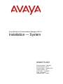
Installation — System
NN40170-303
Document status: Standard
Document issue: 03.03
Document date: February 2011
Product release: 6.0
Job function: Installation
Type: Document
Language type: English
Copyright © 2009 – 2011 Avaya Inc.
All Rights Reserved.
Notices
While reasonable efforts have been made to ensure that the information in this document is complete and accurate at the time of
printing, Avaya assumes no liability for any errors. Avaya reserves the right to make changes and corrections to the information
in this document without the obligation to notify any person or organization of such changes.
Documentation disclaimer
Avaya shall not be responsible for any modifications, additions, or deletions to the original published version of this
documentation unless such modifications, additions, or deletions were performed by Avaya. End User agree to indemnify and
hold harmless Avaya, Avaya’s agents, servants and employees against all claims, lawsuits, demands and judgments arising out
of, or in connection with, subsequent modifications, additions or deletions to this documentation, to the extent made by End
User.
Link disclaimer
Avaya is not responsible for the contents or reliability of any linked Web sites referenced within this site or documentation(s)
provided by Avaya. Avaya is not responsible for the accuracy of any information, statement or content provided on these sites
and does not necessarily endorse the products, services, or information described or offered within them. Avaya does not
guarantee that these links will work all the time and has no control over the availability of the linked pages.
Warranty
Avaya provides a limited warranty on this product. Refer to your sales agreement to establish the terms of the limited warranty.
In addition, Avaya’s standard warranty language, as well as information regarding support for this product, while under
warranty, is available to Avaya customers and other parties through the Avaya Support Web site: http://www.avaya.com/
support
Please note that if you acquired the product from an authorized reseller, the warranty is provided to you by said reseller and not
by Avaya.
Licenses
THE SOFTWARE LICENSE TERMS AVAILABLE ON THE AVAYA WEBSITE, HTTP://
SUPPORT.AVAYA.COM/LICENSEINFO/ ARE APPLICABLE TO ANYONE WHO DOWNLOADS, USES
AND/OR INSTALLS AVAYA SOFTWARE, PURCHASED FROM AVAYA INC., ANY AVAYA AFFILIATE, OR AN
AUTHORIZED AVAYA RESELLER (AS APPLICABLE) UNDER A COMMERCIAL AGREEMENT WITH AVAYA OR
AN AUTHORIZED AVAYA RESELLER. UNLESS OTHERWISE AGREED TO BY AVAYA IN WRITING, AVAYA
DOES NOT EXTEND THIS LICENSE IF THE SOFTWARE WAS OBTAINED FROM ANYONE OTHER THAN AVAYA,
AN AVAYA AFFILIATE OR AN AVAYA AUTHORIZED RESELLER, AND AVAYA RESERVES THE RIGHT TO TAKE
LEGAL ACTION AGAINST YOU AND ANYONE ELSE USING OR SELLING THE SOFTWARE WITHOUT A LICENSE.
BY INSTALLING, DOWNLOADING OR USING THE SOFTWARE, OR AUTHORIZING OTHERS TO DO SO, YOU, ON
BEHALF OF YOURSELF AND THE ENTITY FOR WHOM YOU ARE INSTALLING, DOWNLOADING OR USING THE
SOFTWARE (HEREINAFTER REFERRED TO INTERCHANGEABLY AS "YOU" AND "END USER"), AGREE TO
THESE TERMS AND CONDITIONS AND CREATE A BINDING CONTRACT BETWEEN YOU AND AVAYA INC. OR
THE APPLICABLE AVAYA AFFILIATE ("AVAYA").
Copyright
Except where expressly stated otherwise, no use should be made of the Documentation(s) and Product(s) provided by Avaya. All
content in this documentation(s) and the product(s) provided by Avaya including the selection, arrangement and design of the
content is owned either by Avaya or its licensors and is protected by copyright and other intellectual property laws including the
sui generis rights relating to the protection of databases. You may not modify, copy, reproduce, republish, upload, post, transmit
or distribute in any way any content, in whole or in part, including any code and software. Unauthorized reproduction,
transmission, dissemination, storage, and or use without the express written consent of Avaya can be a criminal, as well as a civil
offense under the applicable law.
Third Party Components
Certain software programs or portions thereof included in the Product may contain software distributed under third party
agreements ("Third Party Components"), which may contain terms that expand or limit rights to use certain portions of the
Product ("Third Party Terms"). Information regarding distributed Linux OS source code (for those Products that have distributed
the Linux OS source code), and identifying the copyright holders of the Third Party Components and the Third Party Terms that
apply to them is available on the Avaya Support Web site: http://support.avaya.com/Copyright.
Trademarks
The trademarks, logos and service marks ("Marks") displayed in this site, the documentation(s) and product(s) provided by
Avaya are the registered or unregistered Marks of Avaya, its affiliates, or other third parties. Users are not permitted to use
such Marks without prior written consent from Avaya or such third party which may own the Mark. Nothing contained in this
site, the documentation(s) and product(s) should be construed as granting, by implication, estoppel, or otherwise, any license or
right in and to the Marks without the express written permission of Avaya or the applicable third party. Avaya is a registered
trademark of Avaya Inc. All non-Avaya trademarks are the property of their respective owners.
Downloading documents
For the most current versions of documentation, see the Avaya Support. Web site: http://www.avaya.com/support
Contact Avaya Support
Avaya provides a telephone number for you to use to report problems or to ask questions about your product. The support
telephone number is 1-800-242-2121 in the United States. For additional support telephone numbers, see the Avaya Web site:
http://www.avaya.com/support
Contents
New in this release
7
Features 7
Multi-Image Hard Drive 7
Introduction
Installation architecture
9
11
System architecture 11
DHCP and IP addressing 12
External DHCP server not available 12
External DHCP server available 13
Mounting options 13
Rack-mount installation 13
Wall-mount installation 13
Desktop-mount installation 14
Miscellaneous features 14
External music source 14
Analog telephones and devices 14
Business Element Manager 14
Startup Profile 14
Line and data connector wiring 14
Avaya BCM450 installation preparation
15
Verifying the expansion cabinet components 17
Preinstallation checklists 17
Avaya BCM450 main unit and expansion cabinet installation
Avaya BCM450 main unit installation
Installing the Avaya BCM450 main unit on a rack
Avaya BCM450 main unit wall-mount installation
19
21
23
25
Mounting the backboard 26
Installing the main unit using a wall-mount bracket 26
Avaya BCM450 main unit desktop installation
Avaya BCM450 expansion cabinet installation
29
31
Avaya BCM450 expansion cabinet installation navigation 32
Mounting the expansion cabinet in an equipment rack 32
Installing the expansion cabinet on a wall 33
Installing the expansion cabinet on a desktop 34
Connecting the expansion cabinet to the main unit 34
MBM installation
37
Configuring the G4x16 or G8x16 DIP switches 39
Configuring the GASM DIP switches 39
Wiring the FEM 40
Configuring MBMs for main unit installation 42
Configuring MBMs for expansion cabinet installation 43
Avaya Business Communications Manager 450 6.0 Installation — System
February 2011
3
Contents
Installing an MBM in the main unit or an expansion cabinet 44
Prerequisites 44
Avaya BCM450 cable connection
Power connection
47
49
Connecting a UPS to your Avaya BCM450 system 51
Connecting the Avaya BCM450 system to a power source 51
Lines and extensions connection
53
Connecting to GATM4/GATM8, and G4x16/8x16 MBMs 54
Connecting to DTM, BRIM, CTM, and 4x16 MBMs 55
Connecting to DSM16+, DSM32+, ASM8 MBMs 56
Auxiliary equipment connection
57
Connecting an auxiliary ringer 59
Connecting an external paging system 60
Connecting the music source using the music source jack 60
Procedure steps 61
LAN connection
63
Connecting the main unit to the LAN 64
Connecting IP devices to the LAN 64
Avaya BCM450 telephone and peripheral installation
Telephone installation
65
67
Installing an emergency telephone 67
IP phone installation 67
Mobility system installation 68
Avaya 7406E Digital Mobile Handset installation 68
Capacity expansion card installation
69
Installing the CEC 69
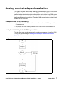
Analog terminal adapter installation
71
Connecting the ATA2 72
Prerequisites 72
Procedure steps 72
Mounting the ATA2 to a wall 72
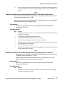
Testing insertion loss measurement from the CO to the analog device 73
Prerequisites 73
Procedure steps 73
Testing insertion loss measurement from the analog device to the CO 73
Prerequisites 73
Procedure steps 73
Configuring the ATA2 74
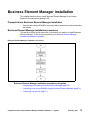
Business Element Manager installation
75
Business Element Manager installation procedures navigation 75
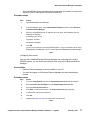
Downloading and installing Business Element Manager 76
Procedure steps 76
Connecting to the Avaya BCM450 through Business Element Manager 76
Prerequisites 77
4
Avaya Business Communications Manager 450 6.0 Installation — System
February 2011
Contents
Procedure steps 77
Avaya BCM450 common procedures
79
Rebooting the Avaya BCM450 79
Avaya BCM450 shut-down 79
Installation troubleshooting 79
Checking LED status 79
Checking DIP switches 80
Troubleshooting
81
Troubleshooting navigation 81
Testing the main unit 81
Use the following procedure to test the main unit. 81
Procedure steps 81
Troubleshooting the main unit 82
If a test fails, use the following procedure to troubleshoot the main unit. 82
Procedure steps 82
Testing an MBM 82
Procedure steps 82
Determining why an MBM does not appear in Business Element Manager 83
Procedure steps 83
Troubleshooting the FEM 83
Procedure steps 83
Troubleshooting the ATA2 83
Troubleshooting dial tone problems with the ATA2 84
Checking ATA2 wiring 84
Avaya BCM450 system reset 84
Preinstallation reference
87
Environmental requirements 87
Electrical requirements 87
Site telephony wiring requirements 88
GASM DIP switch configuration
89
GASM DIP switch configuration 89
Ports and connectors reference
91
Main unit ports and connectors 91
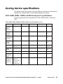
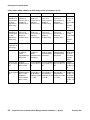
Analog device specifications
93
ATA2, ASM8, ASM8+, GASM, and GASI analog device specifications 93
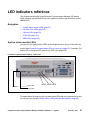
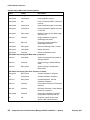
LED indicators reference
97
System status monitor LEDs 97
Hard disk drive LEDs 99
LAN port LEDs 99
Media bay module LEDs 100
DTM LEDs 101
BRIM LEDs 103
System information and tools
105
Media bay modules 105
Avaya Business Communications Manager 450 6.0 Installation — System
February 2011
5
Contents
Additional hardware 106
Tools 107
System information 108
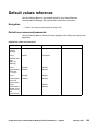
Default values reference
109
Default user names and passwords 109
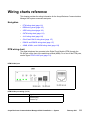
Wiring charts reference
111
DTM wiring chart 111
BRIM wiring chart 112
ADID wiring chart 113
GATM wiring chart 113
4x16 wiring chart 116
G4x16 and G8x16 wiring chart 117
DSM16 and DSM32 wiring chart 117
ASM8, ASM8+, and GASM wiring chart 118
6
Avaya Business Communications Manager 450 6.0 Installation — System
February 2011
New in this release
The following sections detail what’s new in Avaya Business Communications Manager
450 Installation — System (NN40170-303) for Release 6.0:
Features
This document contains information about the following features in Release 6.0.
Multi-Image Hard Drive
Avaya Business Communications Manager 6.0 (Avaya BCM) introduces the new
Multi-Image Hard Drive Field Replaceable Unit (FRU). For more information about new
LED states related to Multi-Image Hard Drives, see LED indicators reference (page 97).
Avaya Business Communications Manager 450 6.0 Installation — System
February 2011
7
New in this release
8 Avaya Business Communications Manager 450 6.0 Installation — System
February 2011
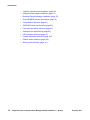
Introduction
This guide describes how to install the Avaya Business Communications Manager 450
Release 6.0 (Avaya BCM450 6.0) system. For information on upgrading to this release,
see the Avaya BCM 6.0 Upgrade Guide (NN40170-401).
The concepts, operations, and tasks described in this guide relate to the Avaya BCM450
system. This guide provides task-based information to install the hardware components.
The Avaya BCM450 6.0 provides private network and telephony management capability
to small- and medium-sized businesses.
All procedures in this guide also apply to systems shipped with a redundant fan and
power supply, as well as systems shipped with a secondary hard disk drive. Any
differences are indicated in the procedure.
The Avaya BCM450 system
•
integrates voice and data capabilities, and IP Telephony gateway functions into a
single telephony system
•
provides telephony applications for use in a business environment
•
Installation architecture (page 11)
•
Avaya BCM450 installation preparation (page 15)
•
Avaya BCM450 main unit and expansion cabinet installation (page 19)
•
Avaya BCM450 main unit installation (page 21)
•
Installing the Avaya BCM450 main unit on a rack (page 23)
•
Avaya BCM450 main unit wall-mount installation (page 25)
•
Avaya BCM450 main unit desktop installation (page 29)
•
Avaya BCM450 expansion cabinet installation (page 31)
•
MBM installation (page 37)
•
Avaya BCM450 expansion cabinet installation (page 31)
•
Avaya BCM450 cable connection (page 47)
•
Power connection (page 49)
•
Lines and extensions connection (page 53)
•
Auxiliary equipment connection (page 57)
•
LAN connection (page 63)
•
Avaya BCM450 telephone and peripheral installation (page 65)
Navigation
Avaya Business Communications Manager 450 6.0 Installation — System
February 2011
9
Introduction
10
•
Capacity expansion card installation (page 69)
•
Analog terminal adapter installation (page 71)
•
Business Element Manager installation (page 75)
•
Avaya BCM450 common procedures (page 79)
•
Preinstallation reference (page 87)
•
GASM DIP switch configuration (page 89)
•
Ports and connectors reference (page 91)
•
Analog device specifications (page 93)
•
LED indicators reference (page 97)
•
System information and tools (page 105)
•
Default values reference (page 109)
•
Wiring charts reference (page 111)
Avaya Business Communications Manager 450 6.0 Installation — System
February 2011
Installation architecture
This chapter describes the architecture of a typical Avaya Business Communications
Manager 450 (Avaya BCM450) system, including the main unit, expansion cabinets,
and related equipment. The mounting options for your Avaya BCM450 system and the
DHCP details are also discussed.
Navigation
•
System architecture (page 11)
•
DHCP and IP addressing (page 12)
•
Mounting options (page 13)
•
Miscellaneous features (page 14)
•
Line and data connector wiring (page 14)
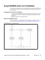
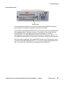
System architecture
The primary hardware component of your Avaya BCM450 system is the main unit. Each
Avaya BCM450 system must have one main unit.
In addition to a main unit, the Avaya BCM450 system can include a Avaya BCM450
expansion cabinet. An expansion cabinet connects to the main unit and provides
additional functionality through one or more installed media bay modules (MBM).
You can connect your Avaya BCM450 system directly to a power source or through an
uninterruptible power supply (UPS).
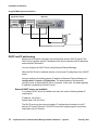
For a visual representation of a Avaya BCM450 system, the following figure.
Avaya Business Communications Manager 450 6.0 Installation — System
February 2011
11
Installation architecture
Avaya BCM450 system architecture
Expansion cabinet
Main unit
UPS
DHCP and IP addressing
Each main unit includes a dynamic host configuration protocol (DHCP) server. This
DHCP server supplies Avaya IP Deskphones and client computers with IP addresses
and connection information.
You can configure the DHCP server using Business Element Manager.
When the DHCP client is enabled, the main unit receives IP configuration from a DHCP
server.
You can configure the default gateway IP address in Business Element Manager at
Configuration > System > IP Subsystem. The default gateway field becomes
read-only when an external DHCP server is present. In this case, the default gateway
IP address is supplied by the DHCP server.
External DHCP server not available
If no external DHCP server is available, the main unit uses the following default IP
configuration:
IP address: 192.168.2.2
Subnet mask: 255.255.254.0
The DHCP server on the main unit supplies IP configuration information for all IP
devices (PCs and IP Phones). The DHCP server also supplies specific connection
information to the IP Phones.
12
Avaya Business Communications Manager 450 6.0 Installation — System
February 2011
Installation architecture
External DHCP server available
If an external DHCP is present, the Avaya BCM450 system uses the IP configuration
supplied by the external DHCP server.
The DHCP server on the main unit must configure a range of IP addresses to supply to
the IP Phones.
The factory default DHCP server address range is set to 192.168.2.3 - 192.168.3.254.
This allows for more than 500 addresses.
Use Business Element Manager to verify and change the default range.
The administrator must ensure that this range works with the network configuration; the
external DHCP server does not use the range.
Mounting options
You typically install the main unit and expansion cabinet in the same manner. Ensure
you install the expansion cabinets close enough to the main unit so you can connect the
supplied 5 m (16 ft) expansion cable between the expansion cabinet and main unit.
Avaya provides three methods to install the Avaya BCM450 units:
•
Rack-mount installation
•
Wall-mount installation
•
Desktop-mount installation
Rack-mount installation
You can install a Avaya BCM450 main unit in a standard 19-inch equipment rack along
with your other networking and telecommunications equipment. You install the Avaya
BCM450 expansion cabinet in a similar manner to the main unit.
Wall-mount installation
You can mount a Avaya BCM450 main unit or expansion cabinet on a wall. To mount
the unit on a wall, you need the following items:
•
A wall-mount bracket kit NTAB3422
•
Four #10 x 2.5 cm (#10 x 1 in.) round-head wood screws
•
A plywood backboard 2 cm (3/4 in.) thick
To mount the expansion cabinet, you need the following items:
•
A wall-mount bracket (supplied with unit)
•
Two #10 x 2.5 cm (#10 x 1 in.) round-head screws
•
A plywood backboard 2 cm (3/4 in.) thick
Avaya Business Communications Manager 450 6.0 Installation — System
February 2011
13
Installation architecture
Desktop-mount installation
You can install a Avaya BCM450 main unit or expansion cabinet on a desktop or a shelf.
Miscellaneous features
The following sections describe some additional features of the Avaya BCM450 system.
External music source
You can connect an external music source for music on hold. For more information
about installing an external music source, see Connecting the music source using the
music source jack (page 60).
Analog telephones and devices
You can use an analog terminal adapter (ATA2) to install analog telephones and data
devices, such as fax machines, on your Avaya BCM450 system. For more information
about installing an ATA2, see Analog terminal adapter installation (page 71).
Business Element Manager
You can use Business Element Manager to configure and monitor your Avaya BCM450
system. For more information about installing Business Element Manager on a PC, see
Business Element Manager installation (page 75).
Startup Profile
An experienced administrator can use the Startup Profile tool with common Avaya BCM
parameters. You can use the Startup profile to quickly configure one or multiple
systems.
Create the Startup Profile using the Startup Profile template (a Microsoft Excel
template). Then use a USB storage device to transfer the Startup Profile data to the
Avaya BCM main unit. For more information about Startup Profile and templates, see
Avaya Business Communications Manager 6.0 Configuration—System
(NN40170-501).
Attention: Voicemail parameters are not available through Startup Profile.
Line and data connector wiring
For information about connecting telephone and data lines to media bay modules
(MBMs), see Lines and extensions connection (page 53). For information about
connecting the Avaya BCM450 to a LAN, see LAN connection (page 63).
14
Avaya Business Communications Manager 450 6.0 Installation — System
February 2011
Avaya BCM450 installation preparation
Verify that your site meets all requirements and that you have the required main unit and
expansion cabinet components before you install the Avaya Business Communications
Manager 450 system.
Prerequisites to Avaya BCM450 installation preparation
•
The Avaya BCM450 expansion cabinet is an optional component. The expansion
module increases the number of media bay modules (MBMs) you can install in the
system.
Avaya BCM 450 installation preparation procedures
This task flow shows you the sequence of procedures you perform to prepare to install
your Avaya BCM450 system. To link to any procedure, go to
Avaya BCM450 installation preparation navigation (page 15).
Avaya BCM450 installation preparation procedures
Avaya BCM450 installation preparation navigation
•
Verifying the site requirements (page 16)
Avaya Business Communications Manager 450 6.0 Installation — System
February 2011
15
Avaya BCM450 installation preparation
•
Verifying the main unit components (page 16)
•
Verifying the expansion cabinet components (page 17)
•
Preinstallation checklists (page 17)
Verifying the site requirements
Before you install the Avaya BCM450 system, verify that your site meets the installation
requirements.
Prerequisites
•
For details about environmental, electrical, and telephony-wiring requirements, see
Preinstallation reference (page 87).
Procedure steps
Step
Action
1
Determine the location for the main unit (and optional expansion cabinet),
telephones, and other equipment.
2
Order the required trunks from the central office.
3
Ensure that the system complies with the environmental requirements.
4
Ensure that the system complies with the electrical requirements.
5
Ensure that the system complies with the site telephony-wiring requirements.
--End--
Verifying the main unit components
Before you install the Avaya BCM450 main unit, verify that you have the required
components and that the components are not damaged.
Procedure steps
Step
16
Action
1
Open the Avaya BCM450 main unit box and remove the components.
2
Verify that you have one Avaya BCM450 main unit.
3
Verify that you have one power supply cable.
4
Verify that you have four rubber feet.
5
Verify that you have one set of rack-mount brackets.
6
Verify that you have a documentation CD.
7
Verify that you have the Installation Checklist and Quick Start Guide.
Avaya Business Communications Manager 450 6.0 Installation — System
February 2011
Avaya BCM450 installation preparation
8
Visually inspect the components for damage during shipping.
9
If you find damage or if you do not have all components, contact your Avaya
sales representative.
--End--
Verifying the expansion cabinet components
Before you install the optional Avaya BCM450 expansion cabinet, verify that you have
the required components, and that they are not damaged.
Procedure steps
Step
Action
1
Open the Avaya BCM450 expansion cabinet box and remove the components.
2
Verify that you have one Avaya BCM450 expansion cabinet.
3
Verify that you have one power supply cable.
4
Verify that you have one expansion cable (shielded Ethernet cable).
5
Verify that you have four rubber feet.
6
Verify that you have the correct media bay modules (MBMs).
7
Visually inspect the components for damage during shipping.
8
If you find damage or if you do not have all components, contact your Avaya
sales representative.
--End--
Preinstallation checklists
For preinstallation checklists, see Installation Checklist and Quickstart Guide.
Avaya Business Communications Manager 450 6.0 Installation — System
February 2011
17
Avaya BCM450 installation preparation
18
Avaya Business Communications Manager 450 6.0 Installation — System
February 2011
Avaya BCM450 main unit and expansion
cabinet installation
To install a Avaya Business Communications Manager 450 system, you must install a
Avaya BCM450 main unit, and an optional expansion cabinets with media bay modules
(MBM).
Prerequisites to main and expansion cabinet installation
•
A Avaya BCM450 system requires a main unit, and can include an optional
expansion cabinet.
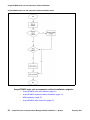
Avaya BCM450 main unit and expansion cabinet installation tasks
This work flow shows you the sequence of tasks you perform to install a main unit and
expansion cabinet. To link to any tasks, go to Avaya BCM450 main unit and expansion
cabinet installation navigation (page 20).
Avaya Business Communications Manager 450 6.0 Installation — System
February 2011
19
Avaya BCM450 main unit and expansion cabinet installation
Avaya BCM450 main unit and expansion cabinet installation tasks
Avaya BCM450 main unit and expansion cabinet installation navigation
20
•
Avaya BCM450 main unit installation (page 21)
•
Avaya BCM450 expansion cabinet installation (page 31)
•
MBM installation (page 37)
•
Avaya BCM450 cable connection (page 47)
Avaya Business Communications Manager 450 6.0 Installation — System
February 2011
Avaya BCM450 main unit installation
This chapter describes how to install a Avaya Business Communications Manager 450
main unit. You can install the main unit in a standard 19-inch equipment rack, on a wall,
or on a desktop.
Prerequisites to main unit installation
•
To operate the Avaya BCM450 main unit at the optimal internal temperature, ensure
the top, sides, and rear clear of obstructions and away from the exhaust of other
equipment.
•
Ensure no objects are on top of the main unit.
Main unit installation tasks
This work flow shows you the sequence of tasks you perform to install a main unit. To
link to any tasks, go to Avaya BCM450 main unit installation navigation (page 22).
Avaya BCM450 main unit installation tasks
Avaya Business Communications Manager 450 6.0 Installation — System
February 2011
21
Avaya BCM450 main unit installation
Avaya BCM450 main unit installation navigation
22
•
Installing the Avaya BCM450 main unit on a rack (page 23)
•
Avaya BCM450 main unit wall-mount installation (page 25)
•
Avaya BCM450 main unit desktop installation (page 29)
Avaya Business Communications Manager 450 6.0 Installation — System
February 2011
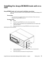
Installing the Avaya BCM450 main unit on a
rack
Avaya BCM450 main unit rack-mount installation procedures
Attach the rack-mount brackets to the Avaya Business Communications Manager 450
main unit.
Prerequisites
•
Use only the screws supplied with the rack-mount bracket. Other screws can
damage the Avaya BCM450 main unit.
Procedure steps
Step
Action
1
Place the Avaya BCM450 main unit on a flat, clean surface.
2
Align the screw holes between the Avaya BCM450 main unit and the right
rack-mount bracket.
3
Fasten the bracket to the Avaya BCM450 main unit using four screws.
Attaching the rack-mount bracket
4
Align the screw holes between the Avaya BCM main unit and the left
rack-mount bracket.
5
Fasten the bracket to the main unit using four screws.
Avaya Business Communications Manager 450 6.0 Installation — System
February 2011
23
Installing the Avaya BCM450 main unit on a rack
6
Determine the location in the rack where you want to install the main unit.
7
Position the main unit in the rack. Have an assistant hold the main unit.
8
Align the holes in the rack-mount bracket with the holes in the equipment rack
rails.
9
Fasten the rack-mount brackets to the rack using the four supplied rack screws.
Mounting the Avaya BCM450 on a rack
--End--
24
Avaya Business Communications Manager 450 6.0 Installation — System
February 2011
Avaya BCM450 main unit wall-mount
installation
This chapter describes how to install a Avaya Business Communications Manager 450
main unit on a wall. To wall-mount a Avaya BCM450 unit, you need a wall-mount
bracket. The Avaya BCM450 unit connects to the wall-mount bracket.
Prerequisites to Avaya BCM450 main unit wall-mount installation
•
wall-mount bracket kit NTAB3422
•
four #10 x 2.5cm (#10 x 1in.) round-head wood screws
•
plywood backboard 2 cm (3/4 in.) thick
Avaya BCM450 main unit wall-mount installation procedures
This task flow shows you the sequence of procedures you perform to install a main unit
on the wall. To link to any procedure, go to Avaya BCM450 main unit wall-mount
installation navigation (page 25).
Avaya BCM450 main unit wall-mount installation procedures
Avaya BCM450 main unit wall-mount installation navigation
•
Mounting the backboard (page 26)
•
Installing the main unit using a wall-mount bracket (page 26)
Avaya Business Communications Manager 450 6.0 Installation — System
February 2011
25
Avaya BCM450 main unit wall-mount installation
Mounting the backboard
Mount a plywood backboard on a wall to simplify installation of your Avaya BCM450
main unit and optional expansion cabinet.
Prerequisites
•
Ensure plywood backboard is 2 cm (3/4 in.) thick.
•
Obtain a pencil, ruler, screwdriver, and a level.
•
Obtain appropriate screws and optional wall anchors to attach the backboard to the
wall.
Procedure steps
Step
Action
1
Use a pencil to mark the desired location of the plywood backboard on the wall.
2
Use a ruler and a level to make sure that the plywood backboard is level.
3
Mount the plywood backboard securely to the wall with appropriate screws.
--End--
Installing the main unit using a wall-mount bracket
To install your Avaya BCM450 system on a wall, you must install a wall-mount bracket
for the main unit and optional expansion cabinet.
Prerequisites
•
Obtain five #8 x 2 cm (#8 x 0.75 in.) round-head wood screws to attach the
wall-mount bracket to the backboard (or wall).
•
Obtain tools for the installation including a screwdriver (for the wood screws), a level,
and a pencil.
Procedure steps
Step
26
Action
1
Place the wall-mount bracket on the backboard (or wall) and mark the location of the
screw holes. Use a bubble level to ensure that the wall-mount bracket is level with the
plywood backboard.
2
Install four #10 x 2.5 cm (#10 x 1 in.) round-head screws in the backboard. Leave
approximately 0.5 cm (0.25 in.) of each screw exposed from the backboard (or wall).
3
Hang the wall-mount bracket on the installed screws.
4
Use a level to make sure the wall-mount bracket is level.
5
Remove the wall-mount bracket from the backboard.
6
Align the screw holes on one side of the Avaya BCM450 main unit with the wall-mount
bracket.
7
Fasten the wall-mount brackets securely to the Avaya BCM450 main unit by using the
screws provided.
Avaya Business Communications Manager 450 6.0 Installation — System
February 2011
Avaya BCM450 main unit wall-mount installation
8
Hang the Avaya BCM main unit on the backboard screws. Make sure the main unit is
level. Ensure the wood screw heads seat fully into the wall-mount bracket slots.
9
Tighten the wood screws against the wall-mount bracket.
--End--
Avaya Business Communications Manager 450 6.0 Installation — System
February 2011
27
Avaya BCM450 main unit wall-mount installation
28
Avaya Business Communications Manager 450 6.0 Installation — System
February 2011
Avaya BCM450 main unit desktop
installation
This chapter describes how to install a Avaya Business Communications Manager 450
main unit on a desktop or other flat surface that can support the weight of the main unit.
Prerequisites
•
Locate the four self-adhesive rubber feet.
•
Leave enough space around the Avaya BCM450 main unit for ventilation and
access to the cables.
Procedure steps
Step
Action
1
Remove the paper backing from the four enclosed self-adhesive rubber feet.
2
Attach the four self-adhesive rubber feet to the bottom of the main unit.
3
Position the main unit on a desktop or shelf.
--End--
Avaya Business Communications Manager 450 6.0 Installation — System
February 2011
29
Avaya BCM450 main unit desktop installation
30
Avaya Business Communications Manager 450 6.0 Installation — System
February 2011
Avaya BCM450 expansion cabinet
installation
This chapter describes how to install a Avaya Business Communications Manager 450
expansion cabinet. You can install the expansion cabinet in a standard 19-inch
equipment rack, on a wall, or on a desktop.
Add an expansion cabinet to increase the capacity of your Avaya BCM450 system.
Prerequisites to expansion cabinet installation
•
To operate the Avaya BCM450 expansion cabinet at the optimal internal
temperature, ensure the top, sides, and rear clear of obstructions and away from the
exhaust of other equipment.
•
Ensure no objects are on top of the expansion cabinet.
Avaya BCM450 expansion cabinet installation procedures
This task flow shows you the sequence of procedures you perform to install an
expansion cabinet. To link to any procedures, go to Avaya BCM450 expansion cabinet
installation navigation (page 32).
Avaya Business Communications Manager 450 6.0 Installation — System
February 2011
31
Avaya BCM450 expansion cabinet installation
Avaya BCM450 expansion cabinet installation procedures
Avaya BCM450 expansion cabinet installation navigation
•
Mounting the expansion cabinet in an equipment rack (page 32)
•
Installing the expansion cabinet on a wall (page 33)
•
Installing the expansion cabinet on a desktop (page 34)
•
Connecting the expansion cabinet to the main unit (page 34)
Mounting the expansion cabinet in an equipment rack
You can install your Avaya BCM450 expansion cabinet in a standard 19-inch equipment
rack.
Prerequisites
•
Use only the screws supplied with the Avaya BCM450 expansion cabinet. Other
screws can damage the Avaya BCM450 expansion cabinet.
Procedure steps
Step
32
Action
1
Place the expansion cabinet on a flat, clean surface.
2
Align the screw holes between the expansion cabinet and the right rack-mount bracket.
Avaya Business Communications Manager 450 6.0 Installation — System
February 2011
Avaya BCM450 expansion cabinet installation
3
Fasten the bracket to the expansion cabinet by using the four screws.
4
Align the screw holes between the expansion cabinet and the left rack-mount bracket.
5
Fasten the bracket to the expansion cabinet by using four screws.
6
Determine the location in the rack where you want to install the expansion cabinet.
7
Position the expansion cabinet in the rack. Have an assistant hold the expansion
cabinet.
8
Align the holes in the rack-mount bracket with the holes in the equipment rack rails.
9
Fasten the rack-mount brackets to the rack using the four supplied rack screws.
--End--
Installing the expansion cabinet on a wall
To mount the Avaya BCM450 expansion cabinet on a wall, you must install the
expansion cabinet on the previously installed wall-mount bracket. You cannot install the
expansion cabinet directly on a wall.
Prerequisites
•
A wall-mount bracket kit (NTAB3422).
•
Obtain five #8 x 2 cm (#8 x 0.75 in.) round-head wood screws to attach the
wall-mount bracket to the backboard (or wall).
•
Obtain tools for the installation including a screwdriver (for the wood screws), a level,
and a pencil.
•
You can install a plywood backboard onto the wall to simplify the installation of the
expansion cabinet. For more information, see Mounting the backboard (page 26).
•
Obtain an appropriate screwdriver.
Procedure steps
Step
Action
1
Place the wall-mount bracket on the backboard (or wall) and mark the location of the
screw holes. Use a bubble level to ensure that the wall-mount bracket is level with the
plywood backboard.
2
Install four #10 x 2.5 cm (#10 x 1 in.) round-head screws in the backboard. Leave
approximately 0.5 cm (0.25 in.) of each screw exposed from the backboard (or wall).
3
Hang the wall-mount bracket on the installed screws.
4
Use a level to make sure the wall-mount bracket is level.
5
Remove the wall-mount bracket from the backboard.
6
Align the screw holes on one side of the Avaya BCM450 expansion cabinet with the
wall-mount bracket.
7
Fasten the wall-mount brackets securely to the Avaya BCM450 expansion cabinet
using the screws provided.
Avaya Business Communications Manager 450 6.0 Installation — System
February 2011
33
Avaya BCM450 expansion cabinet installation
8
Hang the expansion cabinet on the backboard screws. Make sure the expansion
cabinet is level. Ensure the wood screw heads seat fully into the wall-mount bracket
slots.
9
Tighten the wood screws against the wall-mount bracket.
--End--
Installing the expansion cabinet on a desktop
If you cannot install your Avaya BCM450 expansion cabinet in an equipment rack or on
a wall, you can install your expansion cabinet on a desktop or shelf.
Prerequisites
•
Locate the four self-adhesive rubber feet.
•
Leave enough space around the expansion cabinet for ventilation and access to the
cables.
Procedure steps
Step
Action
1
Remove the paper backing from the four enclosed self-adhesive rubber feet.
2
Attach the four self-adhesive rubber feet to the bottom of the expansion cabinet.
3
Position the expansion cabinet on a desktop or shelf.
--End--
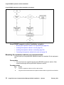
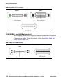
Connecting the expansion cabinet to the main unit
Connect the expansion cabinet to the main unit to gain additional functionality provided
by the MBMs.
Prerequisites
•
A DS256 cable (NTAB3086, supplied).
Attention: The timing in the Avaya BCM450 system is critical. Use the correct length
of cable as supplied with the expansion cabinet (5 m). The system cannot function
properly if you connect the Avaya BCM expansion cabinet using a cable of a different
length.
Procedure steps
Step
1
34
Action
Plug one end of the supplied DS256 cable in the DS256 connector on the expansion
cabinet.
Avaya Business Communications Manager 450 6.0 Installation — System
February 2011
Avaya BCM450 expansion cabinet installation
Expansion cabinet
2
Main unit
Plug the other end of the cable into the DS256 connector on the faceplate of the MSC
in the Avaya BCM450 main unit.
--End--
Avaya Business Communications Manager 450 6.0 Installation — System
February 2011
35
Avaya BCM450 expansion cabinet installation
36
Avaya Business Communications Manager 450 6.0 Installation — System
February 2011
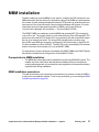
MBM installation
To add a media bay module (MBM) to your system, configure the DIP switches for your
MBM and install it into the main unit or expansion cabinet. Each MBM you add increases
the number of public switched telephone network (PSTN) trunks or extensions that you
can connect to the Avaya Business Communications Manager 450 system. For more
information about the types and functionality of MBMs, see Avaya Business
Communication Manager 450 Installation — Devices (NN40170-500).
The R2MFC MBM is a media bay module (MBM) that provides MFC-R2 connectivity
over an E1 trunk. The module works as a converter between Euro-ISDN and MFC-R2
protocols to allow the MFC-R2 protocol E1 to work directly with the Avaya BCM without
the use of an external converter. The Avaya BCM recognizes the converter as a
Euro-ISDN trunk MBM and, therefore, provides all of the functionality on the MFC-R2
E1 that is available on a Euro-ISDN E1. The MFC-R2 trunk is controlled by DIP switches
and the Command Line Interface (CLI) on the R2MFC MBM.
For instructions to install, configure, and maintain the R2MFC MBM, see R2MFC Media
Bay Module Installation and Configuration Guide (NN40170-304).
Prerequisites to MBM installation
•
The MBMs are safety-approved for installation into the Avaya BCM450 system. The
installer and user must ensure that hardware installation does not compromise
existing safety approvals or local electrical code regulations for telecommunications
equipment and wiring installation.
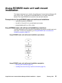
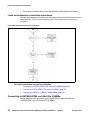
MBM installation procedures
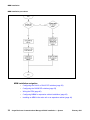
This task flow shows you the sequence of procedures you perform to install an MBM in
a main unit or an expansion cabinet. To link to any procedure, go to see the figure MBM
installation procedures (page 38).
Avaya Business Communications Manager 450 6.0 Installation — System
February 2011
37
MBM installation
MBM installation procedures
MBM installation navigation
38
•
Configuring the G4x16 or G8x16 DIP switches (page 39)
•
Configuring the GASM DIP switches (page 39)
•
Wiring the FEM (page 40)
•
Configuring MBMs for expansion cabinet installation (page 43)
•
Installing an MBM in the main unit or an expansion cabinet (page 44)
Avaya Business Communications Manager 450 6.0 Installation — System
February 2011
MBM installation
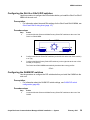
Configuring the G4x16 or G8x16 DIP switches
Use this procedure to configure the DIP switches before you install the G4x16 or G8x16
MBM into the main unit.
Prerequisites
•
For information about lines and DNs settings for the G4x16 and G8x16 MBMs, see
G4x16 and G8x16 wiring chart (page 117)
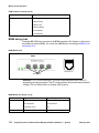
Procedure steps
Step
Action
Locate the Module Select and Mode/Country Select DIP switches at the rear of the
G4x16 or G8x16 MBM.
1
Rear of MBM
ON
123456
12345678
ON
OFF
OFF
Module Select
Mode/Country Select
2
Configure the Module Select DIP switches (on the left side at the rear of the module)
to on (up).
3
Configure the Mode/Country Select DIP switches (on the right side at the rear of the
module) to off (down).
The G4x16 and G8x16 MBMs automatically download the country profiles.
--End--
Configuring the GASM DIP switches
Use the procedure to configure the DIP switches before you install the GASM into the
main unit.
Prerequisites
•
For information about the GASM DIP switch settings, see GASM DIP switch
configuration (page 89).
Procedure steps
Step
1
Action
Locate the Module Select and Mode/Country Select DIP switches at the rear of the
GASM.
Avaya Business Communications Manager 450 6.0 Installation — System
February 2011
39
MBM installation
Rear of MBM
ON
123456
12345678
ON
OFF
OFF
Module Select
Mode/Country Select
2
Configure the Module Select DIP switches (on the left side at the rear of the module)
to on (up).
3
Configure the Mode Select DIP switches (switches 1 to 3, on the right side at the rear
of the module) according to the requirements for your Avaya BCM450 system.
4
Configure the Country Select DIP switches (switches 4 to 8, on the right side at the rear
of the module) according to the regional requirements for your Avaya BCM450 system.
--End--
Wiring the FEM
A fiber expansion module (FEM) allows you to upgrade from a Norstar system to a
Avaya BCM450 system by reusing the Norstar MBMs. The MBMs connect to the FEM
using the same fiber cable that connected them to the Norstar fiber expansion card.
Use the following procedure to connect the fiber cables to the FEM. If you connect a
Norstar station MBM amphenol cable directly to a DSM, you do not have to modify the
wiring connections. Ensure you select the correct DS30 number.
Procedure steps
Step
Action
1
Ensure the Avaya Business Communications Manager50 system is powered up and
functional.
2
Connect the fiber cables from the Norstar MBMs to the jacks on the FEM.
3
Connect the Norstar Line Modules to the FEM beginning at fiber port 1.
4
Connect Norstar Extension Modules to the FEM beginning at fiber port 6.
5
Change the DN records in Business Element Manager or change the set wiring, as
required, to match your system.
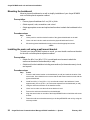
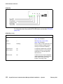
--End-Attention: When you connect a Norstar Station Module to an FEM, the extension
numbers of the telephones connected to the Station Module may change. To keep the
same extension numbers, you must change the DNs of the telephones or change the
telephone wiring to correspond with the required DNs.
40
Avaya Business Communications Manager 450 6.0 Installation — System
February 2011
MBM installation
Attention: If the cable is too long, ensure that it is coiled correctly using the fiber spool.
Coil excess fiber cable carefully around the spool provided. Do not bend the cable
around any tight corners. Bends in the fiber cable must not be less than 100 mm in
diameter. Place the fiber cable spool into a slot at the back of the cable trough in the
Norstar TM or SM.
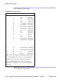
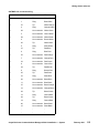
The following table compares the designated extension numbers on the Norstar and on
the Avaya BCM450 systems.
Extension comparison chart
Ports
1
2
3
4
5
6
7
8
9
10
11
12
13
14
15
16
Norstar 221 222 223 224 225 226 227 228 229
230
231 232 233 234 235
236
BCM
234
235 236 229 230 231
232
Norstar 237 238 239 240 241 242 243 244 245
246
247 248 249 250 251
252
BCM
250
251 252 245 246 247
248
Norstar 253 254 255 256 257 258 259 260 261
262
263 264 265 266 267
268
BCM
266
267 268 261 262 263
264
Norstar 269 270 271 272 273 274 275 276 277
278
279 280 281 282 283
284
BCM
282
283 284 277 278 279
280
Norstar 285 286 287 288 289 290 291 292 293
294
295 296 297 298 299
300
BCM
298
299 300 293 294 295
296
Norstar 301 302 303 304 305 306 307 308 309
310
311 312 313 314 315
316
BCM
314
315 316 309 310 311
312
DS30 bus 2, FEM port 1
225 226 227 228 221 222 223 224 233
DS30 bus 3, FEM port 2
241 242 243 244 237 238 239 240 249
DS30 bus 4, FEM port 3
257 258 259 260 253 254 255 256 265
DS30 bus 5, FEM port 4
273 274 275 276 269 270 271 272 281
DS30 bus 6, FEM port 5
289 290 291 292 285 286 287 288 297
DS30 bus 7, FEM port 6
305 306 307 308 301 302 303 304 313
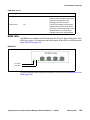
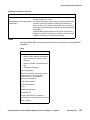
Configuring the MBM DIP switches for main unit installation
Before you install the MBM into the main unit, configure the DIP switches to the default
factory positions.
Procedure steps
Step
1
Action
Locate the DIP switches at the rear or underside of the MBM.
Avaya Business Communications Manager 450 6.0 Installation — System
February 2011
41
MBM installation
Configure all DIP switches to on.
2
--End--
Configuring MBMs for main unit installation
Before installing an MBM in the main unit, configure it through Business Element
Manager and set the DIP switches according to how Business Element Manager
suggests.
Prerequisites
•
Before configuring an MBM, install it in the main unit.
Procedure steps
Step
42
Action
1
In Business Element Manager, navigate to Configuration > Resources > Telephony
Resources.
2
Choose the MBM bay (i.e. Main 1) that you want to configure.
3
Under Configured Device, select the type of MBM you want to install.
4
Press Configure.
Avaya Business Communications Manager 450 6.0 Installation — System
February 2011
MBM installation
5
Enter the Start DN, Public received digits/OLI, Private received digits/OLI, and
Start Line depending on the type of MBM.
6
Select or leave clear the Assign target lines check box.
7
Repeat for each media bay module you want to install.
--End--
Configuring MBMs for expansion cabinet installation
Before installing an MBM in the expansion cabinet, configure it through Business
Element Manager and set the DIP switches according to how Business Element
Manager suggests.
Procedure steps
Step
Action
1
In Business Element Manager, navigate to Configuration > Resources > Telephony
Resources.
2
Select Expansion 1 from the table. A menu appears.
3
Choose the MBM bay (i.e. Expansion 1.1) that you want to configure.
4
Under Configured Device, select the type of MBM you want to install.
5
Press Configure.
6
Enter the Start DN, Public received digits/OLI, Private received digits/OLI, and Start
Line depending on the type of MBM.
7
Select or leave clear the Assign target lines check box.
8
Locate the DIP switches at the rear or underside of the MBM.
Avaya Business Communications Manager 450 6.0 Installation — System
February 2011
43
MBM installation
9
Set the switches to correspond with the settings shown in the Configure window.
10
Repeat for each media bay module you want to install.
--End--
Installing an MBM in the main unit or an expansion cabinet
After configuring the DIP switches on an MBM, you can install it in the Avaya BCM450
main unit or expansion cabinet.
Prerequisites
44
•
Ensure that the DIP switches are configured correctly. For more information about
configuring the DIP switches, see Configuring the G4x16 or G8x16 DIP switches
(page 39), Configuring the GASM DIP switches (page 39), Wiring the FEM
(page 40),or Configuring MBMs for expansion cabinet installation (page 43).
•
MBMs are configured through Business Element Manager. If installing an MBM in
the main unit, configure it after it is installed. If installing the MBM in the expansion
cabinet, configure the MBM before installing it. For more information on configuring
MBMs for the expansion cabinet, see Configuring MBMs for expansion cabinet
installation (page 43)
Avaya Business Communications Manager 450 6.0 Installation — System
February 2011
MBM installation
Attention: Due to power constraints, a maximum of 2 GASM MBMs are supported in
the main unit. Up to 4 GASM MBMs can be installed on the expansion cabinet.
CAUTION
!
Make sure the power supply to the expansion cabinet is
disconnected before inserting or removing an MBM.
CAUTION
!
To prevent damage from electrostatic discharge, always wear an
antistatic wrist strap connected to an ESDS grounding jack whenever
you handle printed circuits.
Procedure steps
Step
Action
1
Select an open media bay.
2
Hold the MBM with the face of the MBM toward you.
3
Push the MBM completely into the MBM bay until you hear a click.
--End--
Avaya Business Communications Manager 450 6.0 Installation — System
February 2011
45
MBM installation
46
Avaya Business Communications Manager 450 6.0 Installation — System
February 2011
Avaya BCM450 cable connection
This chapter describes how to connect the lines, extensions, and auxiliary equipment to
your Avaya Business Communications Manager 450 system. It also describes how to
connect the Avaya BCM450 system to a LAN.
Avaya BCM450 cable connection tasks
This work flow shows you the sequence of tasks you perform to install a main unit and
expansion cabinet. To link to any tasks, go to Avaya BCM450 cable connection
navigation.
Avaya BCM450 cable connection tasks
Avaya Business Communications Manager 450 6.0 Installation — System
February 2011
47
Avaya BCM450 cable connection
Avaya BCM450 cable connection navigation
48
•
Power connection (page 49)
•
Lines and extensions connection (page 53)
•
Auxiliary equipment connection (page 57)
•
LAN connection (page 63)
Avaya Business Communications Manager 450 6.0 Installation — System
February 2011
Power connection
The Avaya Business Communications Manager 450 main unit and expansion cabinet
are each powered through an AC outlet. The voltage required depends on the
geographical location of the units.
All systems are initially configured at the factory based on the intended destination. You
must check that the voltage and wiring are correct for your system before you connect
the units to the power source. Incorrect power settings result in equipment damage.
Read the following warnings. You must protect yourself and the Avaya BCM system
from possible electrical shocks.
!!
WARNING
Risk of injury from electric shock
Connect the ports on station modules only to approved digital
telephones and peripherals with the proper cables on a protected
internal wiring system.
!!
CAUTION
Risk of equipment damage
Service personnel must be alert to the possibility of high leakage
currents becoming available on metal system surfaces during power
line fault events near network lines. These leakage currents normally
safely flow to protective earth ground through the power cord.
System shutdown: You must disconnect the media bay module
cables from the system before you disconnect the power cord from a
grounded outlet.
System startup: You must reconnect the power cords to a grounded
outlet before you reconnect the cables to the media bay modules.
!!
CAUTION
Use only qualified persons to service the system
Service personnel with appropriate training and experience must
perform the installation and service of this unit. Ensure service
personnel are aware of the hazards of working with telephony
equipment and wiring. They must have experience in techniques that
minimize any danger of shock or equipment damage.
Avaya Business Communications Manager 450 6.0 Installation — System
February 2011
49
Power connection
Prerequisites to power connection
•
Install the Avaya BCM450 main unit and optional expansion cabinet. For more
information, see Avaya BCM450 main unit installation (page 21) and Avaya
BCM450 expansion cabinet installation (page 31).
Power connection procedures
This task flow shows you the sequence of procedures you perform to connect power to
your Avaya BCM450 system. To link to any procedure, go to Power supply installation
navigation.
Avaya BCM450 power connection
Power supply installation navigation
50
•
Connecting a UPS to your Avaya BCM450 system (page 51)
•
Connecting the Avaya BCM450 system to a power source (page 51)
Avaya Business Communications Manager 450 6.0 Installation — System
February 2011
Power connection
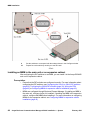
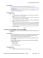
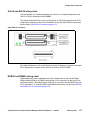
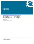
Connecting a UPS to your Avaya BCM450 system
To obtain USB communication between an APC UPS and Avaya BCM450 a USB hub
is not required. APC (American Power Conversion) is the only supported UPS vendor
for Avaya BCM.
Prerequisites
•
For the UPS to function correctly, you must connect it before you power up the
Avaya BCM450 system. If you connect a UPS to a running system, the UPS does
not function.
•
International (non-North American) users require the power supply adapter cord to
connect the power supply to the region specific power bar.
•
Ensure the power supply is within 1.5 m (5 ft) of the Avaya BCM450 unit and within
1.5 m (5 ft) of the UPS.
Procedure steps
Step
Action
1
Connect the UPS to the top port of the Avaya BCM450 main unit, as the bottom port is
reserved for a USB Storage Device.
2
Plug the UPS power cord into the AC power source (wall outlet).
UPS
Main unit
USB Cable
--End--
Connecting the Avaya BCM450 system to a power source
To power your Avaya BCM450 system, connect the main unit and expansion cabinet to
an AC power source. You can connect the power supplies through a UPS or directly to
the AC power source.
Prerequisites
•
Locate the supplied power cord the main unit and optional expansion cabinet.
Avaya Business Communications Manager 450 6.0 Installation — System
February 2011
51
Power connection
•
If you are installing a Avaya BCM450 main unit with an installed redundant power
supply, located the power cord for the second power supply.
•
The power supply must be within 1.5 m (5 ft) of the Avaya BCM450 unit and within
1.5 m (5 ft) of the AC power outlet.
Procedure steps
Step
Action
1
Connect the Avaya BCM450 main power cord to a non-switchable, third-wire
ground AC electrical outlet. If you system has a redundant power supply,
connect both power cords to the outlet.
2
If you have installed a Avaya BCM450 expansion cabinet, connect the expansion
power cord to a non-switchable, third-wire ground AC electrical outlet.
3
If you use a power bar, connect the power cords to the power bar and connect
the power bar to the outlet.
--End--
52
Avaya Business Communications Manager 450 6.0 Installation — System
February 2011
Lines and extensions connection
The telephone lines and extensions connect to the Avaya Business Communications
Manager 450 main unit through an RJ-21 telephony connector on an MBM installed in
the expansion cabinet.
Prerequisites to lines and extensions connection
!
WARNING
Risk of injury from electric shock
Connect the ports on station modules only to approved digital
telephones and peripherals with the proper cables on a protected
internal wiring system.
!
CAUTION
Risk of equipment damage
Service personnel must be alert to the possibility of high leakage
currents becoming available on metal system surfaces during power
line fault events near network lines. These leakage currents normally
safely flow to protective earth ground through the power cord.
System shutdown: You must disconnect the media bay module
cables from the system before you disconnect the power cord from a
grounded outlet.
System startup: You must reconnect the power cords to a grounded
outlet before you reconnect the cables to the media bay modules.
!
CAUTION
Use only qualified persons to service the system
Service personnel with appropriate training and experience must
perform the installation and service of this unit. Ensure service
personnel are aware of the hazards of working with telephony
equipment and wiring. They must have experience in techniques that
minimize any danger of shock or equipment damage.
•
You must connect the power cords to a grounded outlet before you connect the
telephony and data networking cables.
•
Do not connect Digital Station ports (DSM16+, DSM32+) and Analog Station ports
(GASM8) to an exposed plant. This includes Digital Station ports that reside on the
combination MBMs (G4x16 and G8x16). Use only proprietary Avaya Digital Station
Sets to connect to digital ports and agency-approved Analog devices for connection
to the Analog Station ports.
Avaya Business Communications Manager 450 6.0 Installation — System
February 2011
53
Lines and extensions connection
•
Do not connect telephones to wiring that extends to the outside of the building.
Lines and extensions connection procedures
This task flow shows you the sequence of procedures you perform to connect the lines
and extensions. To link to any procedure, go to Lines and extensions connection
navigation.
Lines and extensions connection procedures
Lines and extensions connection navigation
•
Connecting to GATM4/GATM8, and G4x16/8x16 MBMs (page 54)
•
Connecting to DTM, BRIM, CTM, and 4x16 MBMs (page 55)
•
Connecting to DSM16+, DSM32+, ASM8 MBMs (page 56)
Connecting to GATM4/GATM8, and G4x16/8x16 MBMs
Analog telephone lines connect to your Avaya BCM450 system through the
GATM4/GATM8, and G4x16/G8x16 CTM MBMs.
54
Avaya Business Communications Manager 450 6.0 Installation — System
February 2011
Lines and extensions connection
Prerequisites
•
Obtain a 25-pair connector cable with an RJ-21 connector on one end.
•
For detailed information about the wiring of the GATM4 or GATM8, see GATM wiring
chart (page 113).
•
For detailed information about the wiring of the G4x16 or G8x16 MBM, see G4x16
and G8x16 wiring chart (page 117).
Procedure steps
Step
Action
1
If you use the GATM4 or GATM8, plug the RJ-21 end of the connector cable into the
RJ-21 connector on the front of the MBM.
OR
If you have the G4x16 or G8x16 MBM, plug the RJ-21 end of the connector cable into
the lower RJ-21 connector on the front of the MBM.
2
If you use a straight RJ-21 connector, secure the RJ-21 connector to the MBM with the
two supplied screws on the sides of the connector.
OR
If you use a right-angle RJ-21 connector, secure the RJ-21 connector to the MBM with
the supplied screw on the left side of the connector and with the supplied cable tie on
the right side of the connector to fasten the 25-pair cable to the anchor on the MBM.
3
Connect the other end of the connector cable to the telephone company demarcation
blocks of the building.
--End--
Connecting to DTM, BRIM, CTM, and 4x16 MBMs
Connect telephone lines to your Avaya BCM450 system through the DTM, BRIM, and
4x16 MBMs.
Prerequisites
•
If the network ISDN is a U-loop, you must connect the BRIM only to an NT1 provided
by the service provider. The NT1 must provide a Telecommunication Network
Voltage (TNV) to Safety Extra Low Voltage (SELV) barrier.
•
Do not attempt to plug digital equipment into the auxiliary (AUX) jacks on the front
of a 4x16 MBM.
•
Obtain a telephone cable that includes a modular plug that matches the MBM to
which you want to connect:
— RJ-48C for DTM
— RJ-45 for BRIM
— RJ-11 for 4x16 and CTM
Procedure steps
Step
1
Action
Plug the modular cable into the jack in the front of the MBM.
Avaya Business Communications Manager 450 6.0 Installation — System
February 2011
55
Lines and extensions connection
The 4x16 is connected using a 25-pair connector cable.
2
Connect the other end of the cable to the telephone company demarcation blocks of
the building.
3
To connect additional analog lines to a 4x16 MBM or BRIM, repeat step 1 and step 2
for each line.
--End--
Connecting to DSM16+, DSM32+, ASM8 MBMs
You can connect telephones to your Avaya BCM450 system through the DSM16+,
DSM32+, ASM8 MBMs.
Prerequisites
•
Obtain a 25-pair connector cable with an RJ-21 connector on one end.
•
Do not connect the digital station ports of the DSM16+, DSM32+, or combination
MBMs to the PSTN. Only approved digital telephones or peripheral devices can
connect to the DSM16+, DSM32+, and combination MBMs.
Attention: ASM8 does not support digital telephones.
Procedure steps
Step
Action
1
If you use the DSM16+, DSM32+, ASM8, or 4x16 MBM, plug the RJ-21 end of the
connector cable into the RJ-21 connector on the front of the MBM.
2
If you use a straight RJ-21 connector, secure the RJ-21 connector to the MBM with the
two supplied screws on the sides of the connector.
OR
If you use a right-angle RJ-21 connector, secure the RJ-21 connector to the MBM with
the supplied screw on the left side of the connector and with the supplied cable tie on
the right side of the connector to fasten the 25-pair cable to the anchor on the MBM.
3
Connect the other end of the cable to the local connecting blocks.
4
If you connect extensions to a DSM32, repeat step 1 to step 2 for the second RJ-21
connector.
--End--
56
Avaya Business Communications Manager 450 6.0 Installation — System
February 2011
Auxiliary equipment connection
The main unit includes connections for an auxiliary ringer, an external paging system,
and a music source.
Prerequisites to auxiliary equipment connection
!
CAUTION
SELV warning
External equipment connected to the auxiliary ringer, page relay,
page output, and music-on-hold interfaces must use safety extra low
voltage (SELV). All four auxiliary interfaces use SELV, and the
external equipment connected to these interfaces must use SELV, or
you must use external line isolation units (LIU).
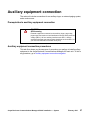
Auxiliary equipment connection procedures
This task flow shows you the sequence of procedures you perform to install auxiliary
equipment to the Avaya Business Communications Manager 450 main unit. To link to
any procedure, go to Auxiliary equipment connection navigation.
Avaya Business Communications Manager 450 6.0 Installation — System
February 2011
57
Auxiliary equipment connection
Auxiliary equipment connection procedures
58
Avaya Business Communications Manager 450 6.0 Installation — System
February 2011
Auxiliary equipment connection
Auxiliary equipment connection navigation
•
Connecting an auxiliary ringer (page 59)
•
Connecting an external paging system (page 60)
•
Connecting the music source using the music source jack (page 60)
Connecting an auxiliary ringer
An auxiliary ringer is a customer-supplied piece of hardware that provides external
ringing capability to telephones on the Avaya BCM450 system.
Prerequisites
•
You must not connect auxiliary ringer to unprotected plant wiring. The ringer must
not draw more than 50 mA from a 40 V DC source.
Procedure steps
Step
Action
1
Install the auxiliary ringer using the installation instructions supplied with the ringer
hardware.
2
Connect the ringer generator to the auxiliary ringer connection on the Base Function
Tray.
--End--
Avaya Business Communications Manager 450 6.0 Installation — System
February 2011
59
Auxiliary equipment connection
Connecting an external paging system
You can connect a customer-supplied external paging system to provide paging over
external loudspeakers.
Prerequisites
•
You must connect the paging connections to unprotected telephony plant wiring.
•
External paging does not support talk back paging equipment unless you use an
external line port. The Avaya BCM450 system provides paging over the telephone
speakers when no external paging equipment is available.
•
Ensure the paging system follows these guidelines:
— The paging output from the main unit is 100 mV rms across an input impedance
of 600 Ω.
— The output level is 0 dBm0 with reference to 600 ohms for a PCM encoded signal
at 0 dBm. No DC voltage exists across the page output terminals. When you use
the page signal output to connect an external paging amplifier, you also use the
page relay output that contains a floating relay contact pair. The system uses this
output to control the external paging amplifier.
— The contact pair for the page relay output has a switch capacity of
50 mA (non inductive) at 40 V (maximum).
Procedure steps
Step
Action
1
Install the external paging hardware using the installation instructions supplied with the
external paging system.
2
Connect the paging system audio input to the page output connection.
3
Connect the paging system relay to the page relay output connection.
4
Verify that the external paging system functions properly.
--End--
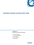
Connecting the music source using the music source jack
You can use a customer-supplied, low-power device as a music source. A music source
includes equipment such as a radio with a high-impedance earphone jack.
Prerequisites
•
Ensure that the music source follows these guidelines:
— Nominal input impedance is 3.3 kilohms.
— Nominal sensitivity of this interface returned to digital encoded PCM is –22 dBm0
for a 0.25 V rms input signal.
— The input is limited so that the encoded analog content at the digital interface to
the network does not exceed –12 dBm when averaged over a three-second
interval.
60
Avaya Business Communications Manager 450 6.0 Installation — System
February 2011
Auxiliary equipment connection
— The maximum nonclipped input level is 1 V rms.
— The interface is protected against ringing cross.
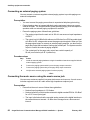
Procedure steps
Step
1
Action
Connect the miniature jack of the music source output (3.5 mm mono audio jack) to the
music source input on the Avaya BCM450 main unit.
BCM450
Music jack
(3.5 mm mono audio jack)
Music source
Tip
Sleeve
Tip: Music signal
Ring: No connection
Sleeve: Ground
2
Adjust the volume of the music source to an appropriate level by placing a call and
placing it on hold, and then adjust the volume at the music source.
--End--
Avaya Business Communications Manager 450 6.0 Installation — System
February 2011
61
Auxiliary equipment connection
62
Avaya Business Communications Manager 450 6.0 Installation — System
February 2011
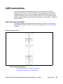
LAN connection
Connect the LAN cables to provide LAN access to your system and to enable
connection of IP devices to the LAN through the Avaya Business Communications
Manager 450 main unit. If you are connecting to the Avaya BCM450 using a Virtual
Local Area Network (VLAN), enter the VLAN IP address. For more information about
VLANs, see Avaya Business Communications Manager 6.0 Configuration — Telephony
(NN40170-502).
LAN connection procedures
This task flow shows you the sequence of procedures you perform to connect your
Avaya BCM450 system to the LAN. To link to any procedures, go to LAN connection
navigation.
LAN connection procedures
LAN connection navigation
•
Connecting the main unit to the LAN (page 64)
•
Connecting IP devices to the LAN (page 64)
Avaya Business Communications Manager 450 6.0 Installation — System
February 2011
63
LAN connection
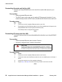
Connecting the main unit to the LAN
Connect your Avaya BCM450 main unit to the LAN to enable LAN access for your
system.
Prerequisites
•
Obtain a standard Ethernet cable.
•
The DHCP server on the main unit is enabled (IP Phones only) by default. If your
network already contains a DHCP server, disable the DHCP server on the main unit.
Procedure steps
Step
Action
1
Connect one end of a standard Ethernet cable to your LAN.
2
Plug the other end of the Ethernet cable into one of the available two LAN ports on the
Avaya BCM450 main unit (two right-most ethernet ports).
The OAM port does not support VoIP devices.
--End--
Connecting IP devices to the LAN
Connect IP devices to the LAN to provide additional functionality to your Avaya BCM450
system.
Prerequisites
•
Obtain a standard Ethernet cable for each IP device.
•
A properly configured layer 2 switch in the network.
CAUTION
!
The two LAN ports on the Avaya BCM450 are set up in a bridge
configuration (both ports use the same IP address). Do not connect
IP devices to both ports at the same time to avoid service problems.
Procedure steps
Step
Action
1
Connect one end of a standard Ethernet cable to an IP device.
2
Connect the other end of the Ethernet cable into one an available ports on the layer 2
switch.
3
Connect the switch to one of the available LAN ports.
4
Repeat step 1 and step 2 for each IP device you want to connect to the LAN.
--End--
64
Avaya Business Communications Manager 450 6.0 Installation — System
February 2011
Avaya BCM450 telephone and peripheral
installation
This chapter describes how to install and configure telephones and other peripheral
devices for Avaya Business Communications Manager 450.
Avaya BCM450 telephone and peripheral installation navigation
•
Telephone installation (page 67)
•
Capacity expansion card installation (page 69)
•
Analog terminal adapter installation (page 71)
Avaya Business Communications Manager 450 6.0 Installation — System
February 2011
65
Avaya BCM450 telephone and peripheral installation
66
Avaya Business Communications Manager 450 6.0 Installation — System
February 2011
Telephone installation
This chapter describes how to connect telephones to your Avaya Business
Communications Manager 450 system.
Prerequisites to telephone installation
•
To operate the Avaya BCM450 expansion cabinet at the optimal internal
temperature, ensure the top, sides, and rear clear of obstructions and away from the
exhaust of other equipment.
•
Ensure no objects are on top of the expansion cabinet.
Telephone installation navigation
•
Installing an emergency telephone (page 67)
•
IP phone installation (page 67)
•
Mobility system installation (page 68)
•
Avaya 7406E Digital Mobile Handset installation (page 68)
Installing an emergency telephone
You can use an emergency telephone to make calls when no power is going to the
Avaya BCM450 system. You can connect an emergency telephone to every CTM/GATM
installed in your Avaya BCM450 system.
Prerequisites
•
A CTM/GATM MBM installed in your Avaya BCM450 system. For more information
about installing MBMs, see MBM installation (page 37).
•
A single line analog telephone is required.
Procedure steps
Step
Action
1
Connect a single line analog telephone to the auxiliary port on the CTM/GATM.
2
Connect an analog PSTN line cable to the line 1 port of the CTM/GATM.
--End--
IP phone installation
Configure the system to automatically assign DNs to the Avaya IP Deskphones. If you
choose to manually assign DNs, choose DNs from unused DNs in the digital range.
Ensure that you do not assign DNs that are assigned to Call Center mailboxes (CDNs).
Avaya Business Communications Manager 450 6.0 Installation — System
February 2011
67
Telephone installation
Mobility system installation
All radio-based mobility systems have documentation that describes the hardware and
installation and activation of the handsets.
The Avaya BCM main unit can support a maximum of two Avaya 7400 Series DECT
Handsets, which are the call processing units between the Avaya BCM main unit and
the Avaya 7400 Series DECT Base Stations and handsets. The DMCs have a
one-to-one connection with digital ports on the Avaya BCM main unit.
For installation and configuration details, see the Digital Mobility Installation and
Configuration Guide (N0000623).
Avaya 7406E Digital Mobile Handset installation
The Avaya 7406E Digital Mobile Handset system consists of a base station that
connects up to four digital station ports on the Avaya BCM450 system, that provide a
radio interface for four cordless handsets. The cordless handsets register to the base
station, which transfers the call over the telephone lines connected to the system. The
handsets are configured to emulate the T7316/M7310 telephone features. This system
is most suited for small- to medium-sized office environments that are set up in an open
fashion.
For installation and configuration details, refer to the Avaya 7406E Digital Mobile
Handset Installation and Configuration Guide (NN40110-301).
68
Avaya Business Communications Manager 450 6.0 Installation — System
February 2011
Capacity expansion card installation
This chapter describes how to install the optional capacity expansion card (CEC) into
the Avaya Business Communications Manager450 main unit. The CEC provides
increased media processing capacity to support up to 300 stations and 130 trunks, as
well as the associated increases in application capacity.
Installing the CEC
Use the following procedure to install the CEC in the main unit.
Prerequisites
•
Power down the Avaya BCM450 system.
•
You will require a Phillips head screwdriver.
•
Ensure the Avaya BCM450 main unit is disconnected from the AC power source.
!
CAUTION
Risk of damage to equipment
You must wear an antistatic grounding strap at all times when
handling electronic components. Failure to do so can result in
damage to the equipment.
Procedure steps
Step
Action
1
Power down the Avaya BCM 450 system and remove the base function tray.
2
Attach one end of a grounding strap to your wrist and the other end to a grounded metal
surface.
3
Remove the plastic cap on the CEC slot on the front of the base function tray by
applying pressure to the bottom of the faceplate from the inside of the Base Function
tray. Once the bottom has come loose, remove the faceplate from the front.
Avaya Business Communications Manager 450 6.0 Installation — System
February 2011
69
Capacity expansion card installation
CEC slot
CEC slot
4
Screw the four metal standoffs (included) into the main board of the base function tray.
5
Slide the CEC into position from the back of the base function tray, so that the CEC
protrudes slightly from the front faceplate of the base function tray.
6
Align the connectors on the card and on the main board of the base function tray and
push down. Ensure that the card is connected securely to the main board.
7
Use the four supplied screws to fasten the card to the standoffs.
8
Reinstall the base function tray and power on the Avaya BCM450 system.
--End--
70
Avaya Business Communications Manager 450 6.0 Installation — System
February 2011
Analog terminal adapter installation
This chapter describes how to install an analog terminal adapter (ATA) or ATA2 for the
Avaya Business Communications Manager 450. You can use an ATA to connect a
standard analog voice device or data communication device to the Avaya BCM system
through a digital station module. Examples of analog voice devices include analog
telephones and answering machines. Examples of data communication devices include
modems and fax machines.
Prerequisites to ATA2 installation
•
In North America, the ATA2 must be powered from a UL- and CSA-approved Class
2 power source.
•
In Europe, the ATA2 must be powered from a Class II power source that is CE
marked.
Analog terminal adapter installation procedures
This task flow shows you the sequence of procedures you perform to install an ATA2.
To link to any procedures, go to Analog terminal adapter installation procedures
(page 71).
Analog terminal adapter installation procedures
Avaya Business Communications Manager 450 6.0 Installation — System
February 2011
71
Analog terminal adapter installation
Analog terminal adapter installation procedures navigation
•
Connecting the ATA2 (page 72)
•
Mounting the ATA2 to a wall (page 72)
•
Testing insertion loss measurement from the CO to the analog device (page 73)
•
Testing insertion loss measurement from the analog device to the CO (page 73)
•
Configuring the ATA2 (page 74)
Connecting the ATA2
After you have set up the correct environment, connect the Avaya BCM system and the
analog device to the ATA2, and then connect the power.
Prerequisites
•
An available station port on the Avaya BCM450 system is required.
Procedure steps
Step
Action
1
Connect one end of a line cord to the ATA2 terminal jack.
2
Connect the other of the line cord to your telephone, modem, or fax machine.
3
Connect one end of a line cord to the ATA2 line jack.
4
Connect the other end of the line cord to an available digital station port.
5
For a 120 V or 230 V system, plug the DIN connector of the power supply cord into the
power supply connector receptacle.
6
Plug the adapter into a standard AC outlet.
--End--
Mounting the ATA2 to a wall
After you connect the ATA2, you can mount it on a wall.
Prerequisites
•
You require 2 4-mm (#8) screws.
•
When using 0.5mm wire (24 AWG), select a location within 800 m (2600 ft.) of the
Avaya BCM450 main unit.
•
Allow 12.5 cm (5 in.) clearance for the line jack, terminal jack, and power supply
connector.
Procedure steps
Step
1
72
Action
Screw two 4-mm (#8) screws into the wall, 130 mm (5 1/4 in.) away from each other.
Leave 6 mm (1/4 in.) of the two screws showing.
Avaya Business Communications Manager 450 6.0 Installation — System
February 2011
Analog terminal adapter installation
Align the slots at the back of the ATA2 unit over the screws. Push the unit against the
wall. The line jack, terminal jack, and power supply connector must be at the top of the
ATA2.
2
--End--
Testing insertion loss measurement from the CO to the analog device
The maximum loss for ATA2 to Central Office (CO) configuration must not exceed 10
dB, and must be greater than —10 dB.
Measure the total insertion loss between the CO and analog device by using standard
dial-up test lines with a transmission test set.
Prerequisites
•
You will need a transmission test set (for example, Hewlett-Packard 4935A
Transmission Test Set).
Procedure steps
Step
Action
1
Establish a connection to the 1 mW, 1 kHz, CO service line with an analog telephone
connected to the ATA2.
2
Replace the analog telephone with the test set.
3
Use RECEIVE/600 OHM/HOLD mode on the test set.
4
Ensure that the analog port terminates correctly in 600 ohms.
5
Ensure that the test set connects in parallel to the service line before you remove the
analog telephone or the line drops.
6
Remove the single-line telephone.
7
Measure the 1 kHz tone at the far end of the analog port, where the analog loop ends
and the analog device connects.
--End--
Testing insertion loss measurement from the analog device to the CO
The maximum loss for ATA2 to Central Office (CO) configuration must not exceed
10 dB and must be greater than —10 dB.
Measure the total insertion loss between the CO and analog device by using
standard dial-up test lines with a transmission test set.
Prerequisites
•
You will need a transmission test set (for example, Hewlett-Packard 4935A
Transmission Test Set).
Procedure steps
Step
1
Action
Establish a connection to a silent termination on the CO service line with an analog
telephone connected to the ATA2.
Avaya Business Communications Manager 450 6.0 Installation — System
February 2011
73
Analog terminal adapter installation
2
Replace the analog telephone with the test set.
3
Use RECEIVE/600 OHM/HOLD mode on the test set.
4
Ensure that the analog port terminates correctly in 600 ohms.
5
Ensure that the test set connects in parallel to the service line before you remove the
analog telephone or the line drops.
6
Remove the single-line telephone.
7
Introduce a 1 kHz tone into the analog line at —10 dBm, and measure the level at the
CO exchange.
--End--
Configuring the ATA2
Configure the ATA2 using Business Element Manager or Telset Administration. For
detailed configuration information, see Avaya Business Communications Manager 450
1.0 Configuration—Devices (NN40170-500).
74
Avaya Business Communications Manager 450 6.0 Installation — System
February 2011
Business Element Manager installation
This chapter describes how to install Business Element Manager for the Avaya
Business Communications Manager 450.
Prerequisites to Business Element Manager installation
•
Ensure that the Avaya BCM450 is correctly installed, powered up, and connected to
the network.
Business Element Manager installation procedures
This task flow shows you the sequence of procedures you perform to install Business
Element Manager. To link to any procedures, go to Business Element Manager
installation procedures navigation.
Business Element Manager installation procedures
Business Element Manager installation procedures navigation
•
Downloading and installing Business Element Manager (page 76)
•
Connecting to the Avaya BCM450 through Business Element Manager (page 76)
•
Configuring user access (page 77)
Avaya Business Communications Manager 450 6.0 Installation — System
February 2011
75
Business Element Manager installation
Downloading and installing Business Element Manager
After your computer connects to the Avaya BCM450 system, either through an Ethernet
crossover cable or through a LAN connection, you can use Application Launcher to
install and run Business Element Manager. Use Business Element Manager to connect
to and configure your Avaya BCM450 system.
The Avaya BCM applications for Avaya BCM450 support Microsoft Vista Business,
Microsoft Vista Ultimate, Microsoft Vista Enterprise, Windows 7, and Windows Server
2008 Release 2. Both 32-bit and 64-bit versions of Windows Vista and Windows 7 are
supported except for the limitations identified in Avaya Business Communications
Manager — System Overview (NN40170-103).
The Business Element Manager is compatible with Windows XP, and Windows Vista,
Windows 7 (32 and 64 bit versions), Windows Server 2003, and Windows Server 2008,
and Windows Server 2008 Release 2 operating systems.
Prerequisites
•
A minimum 256 MB of RAM is required; 512 MB of RAM is recommended.
•
150 MB of available hard disk space is required.
•
Business Element Manager access is also supported through a Citrix server.
Procedure steps
Step
Action
Open a Web browser and enter the Avaya BCM system IP address.
1
The Enter Network Password dialog box appears.
Enter the user name and password (see the following for defaults):
2
Username: nnadmin
Password: PlsChgMe!
Click OK.
3
The Welcome to BCM Web page appears.
4
On the Welcome to BCM Web page, click BCM under Application Selection.
5
From the Application Launcher panel, double-click Business Element Manager.
Business Element Manager is downloaded and launched.
--End--
Connecting to the Avaya BCM450 through Business Element Manager
After you install Business Element Manager on your PC, use it to connect to the Avaya
BCM450 system.
Prerequisites
•
76
Business Element Manager must be installed on your PC.
Avaya Business Communications Manager 450 6.0 Installation — System
February 2011
Business Element Manager installation
•
Your Avaya BCM must be powered on and connected to the network, or connected
directly to your PC through the OAM port or serial port.
Procedure steps
Step
Action
1
Open Business Element Manager.
2
From the Network menu, select New Network Element, and then select Business
Communications Manager.
3
Enter the Avaya BCM system IP address, the user name, and password (see the
following for defaults):
IP address: 192.168.2.2
Username: nnadmin
Password: PlsChgMe!
Click OK.
4
You are now connected to the Avaya BCM system. For more information about using
Business Element Manager, see the online Help within Business Element Manager.
--End--
Configuring user access
After you have installed Business Element Manager and connected to the Avaya
BCM450 system, you can create and configure user accounts for Business Element
Manager.
Prerequisites
•
Business Element Manager must be installed on your PC.
•
You must be logged on to Business Element Manager and have administrator
access.
Procedure steps
Step
Action
1
From the Configuration tab, click the Administrator Access folder to expand it.
2
Select Accounts and Privileges from the Administrator Access folder.
3
Select the View by Accounts tab.
4
Click Add... to add a user account. The Add Account dialog box appears.
5
Configure the Add Account attributes.
6
Click Ok.
7
Repeat steps step 4 to step 6 to create more user accounts.
--End--
Avaya Business Communications Manager 450 6.0 Installation — System
February 2011
77
Business Element Manager installation
Add account attributes
Attribute
Description
Description
Enter a description for this account.
User ID
Enter a descriptive name for the user or the user function.
Password
Enter a password for this account.
Telset user ID (numeric)
If the user performs administration through the Telset interface, enter a
number for the user ID.
Telset password
(numeric)
Enter a password for the Telset User ID.
Modem Callback Number If Callback is required, enter the number to which the system calls back
to verify the dial-up user access.
Modem Callback
Passcode
This is the code the system uses to confirm the callback is legitimate.
ISDN Callback Number
If ISDN Callback is required, enter the number to which the system
calls back to verify the dial-up user access.
ISDN Callback Passcode This is the code the system uses to confirm that the ISDN callback is
legitimate.
Change Password On
Login
Select this check box to force the user to change the password upon
first login.
Change Password On
Login Telset
Select this check box to force the user to change the Telset password
upon first log in.
78
Avaya Business Communications Manager 450 6.0 Installation — System
February 2011
Avaya BCM450 common procedures
This chapter describes common procedures for the Avaya Business Communications
Manager 450 system.
Avaya BCM450 common procedures navigation
•
Rebooting the Avaya BCM450 (page 79)
•
Avaya BCM450 shut-down (page 79)
•
Installation troubleshooting (page 79)
Rebooting the Avaya BCM450
You can reboot the Avaya BCM450 system through Business Element Manager. For
information to install Business Element Manager, see Business Element Manager
installation (page 75).
Prerequisites
•
The Business Element Manager must be installed on a PC connected to the Avaya
BCM450 system, either through the LAN, soft modem, ISDN, or directly through the
OAM port.
Procedure steps
Step
Action
1
Check for a recent backup of the Avaya BCM450 system programming.
2
If no recent backup is available, use Business Element Manager to back up the system
data. For information about backing up the system data, see Avaya Business
Communication Manager 450 6.0 — Administration and Security (NN40170-603).
3
From the Administration tab, click the Utilities folder to expand it.
4
From the Utilities folder, select Reboot.
5
Click Reboot to reboot the system.
--End--
Avaya BCM450 shut-down
For information about shutting down an in-service Avaya BCM450 system, see
Business Communications Manager 450 6.0 — Maintenance (NN40170-503).
Installation troubleshooting
This section describes how to troubleshoot a Avaya BCM450 installation.
Checking LED status
You can use the status and power LEDs on the faceplate of the Avaya BCM450 base
function tray to help troubleshoot hardware issues. For more information about system
LEDs, see LED indicators reference (page 97).
Avaya Business Communications Manager 450 6.0 Installation — System
February 2011
79
Avaya BCM450 common procedures
Checking DIP switches
Problems also arise if you set the DIP switches on your installed MBMs incorrectly. For
information about setting DIP switches, see MBM installation (page 37).
80
Avaya Business Communications Manager 450 6.0 Installation — System
February 2011
Troubleshooting
Troubleshooting
This chapter describes how to troubleshoot the Avaya Business Communications
Manager 450 system.
Troubleshooting navigation
•
Testing the main unit (page 81)
•
Troubleshooting the main unit (page 82)
•
Determining why an MBM does not appear in Business Element Manager (page 83)
•
Troubleshooting the FEM (page 83)
•
Troubleshooting the ATA2 (page 83)
•
Troubleshooting dial tone problems with the ATA2 (page 84)
•
Checking ATA2 wiring (page 84)
•
Avaya BCM450 system reset (page 84)
Testing the main unit
Use the following procedure to test the main unit.
Procedure steps
Step
Action
1
Go to an extension that is connected to the RJ-21 telephony connector on the main
unit.
2
Check for a dial tone.
3
Use this extension to make a call to another extension on the system.
4
If this system is connected to an expansion cabinet with a media bay module (MBM)
that supports extensions, repeat steps 2 and 3 for an extension connected to the
expansion cabinet.
5
Go to an extension that has access to one of the lines on the main unit.
6
Select the line or line pool to which the line belongs.
7
Check for a dial tone.
8
Make a call using the line or line pool.
9
If this system is connected to an expansion cabinet with an MBM that supports lines,
repeat steps 6 to 8 with an extension that can access one of the lines connected to the
expansion unit.
--End--
Avaya Business Communications Manager 450 6.0 Installation — System
February 2011
81
Troubleshooting
Troubleshooting the main unit
If a test fails, use the following procedure to troubleshoot the main unit.
Procedure steps
Step
Action
1
Verify that no nonfunctional features are included in your installed keycode.
2
Check the wiring to the main unit and to the MBMs. Make sure that the cables are
properly seated and are connected to the correct ports.
3
Reboot the Avaya BCM450 system.
4
Check the LEDs.
5
Use Business Element Manager or the Telset Administration feature to check the
programming for the lines or extensions that failed the call test.
6
If the programming is incorrect, use the Backup and Restore Utility to load a recent
backup of system programming. If a recent backup is not available, correct the
programming using Business Element Manager or the Telephone Administration
feature.
--End--
Testing an MBM
Use the following procedure to test an MBM installed in the main unit or expansion
cabinet.
If you are experiencing an issue with an FEM, ensure all DIP switches are set to the On
position. For more information, see Wiring the FEM (page 40).
Procedure steps
Step
Action
1
Check the Power and Status LEDs on the MBM. Both LEDs must be solid green. If
either LED is not solid green, a problem exists with the MBM.
2
Go to an extension on the MBM if it is a station MBM.
OR
Go to an extension that has access to one of the lines on the MBM if it is a trunk MBM.
Select the line or line pool to which the line belongs.
3
Check for a dial tone.
4
Use this extension to make a call to another extension on the system if it is a station
MBM.
OR
Make a call using the line or line pool if it is a trunk MBM.
5
82
Use this extension to make a call to an external telephone number if you are testing a
station MBM.
Avaya Business Communications Manager 450 6.0 Installation — System
February 2011
Troubleshooting
--End--
Determining why an MBM does not appear in Business Element Manager
Use the following procedure if an installed MBM does not appear in Business Element
Manager.
Procedure steps
Step
Action
1
Check that the correct feature is included in your installed keycode.
2
Check that both the Power and Status LEDs on the MBM are solid green.
3
If the Power LED is off, and the MBM is installed in the expansion cabinet, check that
the power supply cable is properly seated in the expansion cabinet and the power
supply is connected to a working power outlet.
4
Ensure that the MBM is properly seated in the MBM bay.
5
If the Status LED is not solid green, and the MBM is installed in the expansion cabinet,
check that the Expansion cable is properly seated in the Expansion port on the
expansion cabinet and on the main unit.
6
Ensure that the MBM is enabled using either Business Element Manager or Telset
Administration. If the MBM is enabled, disable and re-enable it.
7
Ensure that all DIP switches are set correctly. For more information, see MBM
installation (page 37).
--End--
Troubleshooting the FEM
Use the following procedure to troubleshoot an installed fibre expansion module (FEM).
Procedure steps
Step
Action
1
Ensure that all six connector LEDs are lit.
2
If all six LEDs are not lit, ensure that all six DIP switches are set to the On (up) position.
For more information, see Wiring the FEM (page 40).
--End--
Troubleshooting the ATA2
Use the following procedure to troubleshoot a non-functioning ATA2.
Step
Action
1
Check for a dial tone using an analog device.
2
Check that AC power is connected to the ATA2 unit.
3
Check that the correct feature for digital sets is included in your installed keycode.
4
Verify that the ATA2 is connected to a digital station port.
Avaya Business Communications Manager 450 6.0 Installation — System
February 2011
83
Troubleshooting
5
Allow sufficient startup time (30–60 sec).
6
Plug an analog device into the phone port of the ATA2 and check for a dial-tone.
--End--
Troubleshooting dial tone problems with the ATA2
Use the following procedure if there is no dial tone on the ATA2
Step
Action
1
If you hear no dial tone, replace a single-line telephone for the data communication
device.
2
If you hear no dial tone at the ATA2 unit disconnect the line side of the ATA2.
3
Connect a digital telephone to the ATA2 port.
4
Check that the connection from the ATA2 to the Avaya BCM450 hardware works
correctly.
--End--
Checking ATA2 wiring
If the problem with the ATA2 persists, use the following procedure to check the wiring.
Step
Action
1
Use an analog phone to test the ATA2.
2
Check the connection from the ATA2 to the terminal. The resistance must be 200 ohms
or less for data applications and 1300 ohms or less for voice applications.
3
Check the connection from the Avaya BCM450 hardware to the ATA2.
4
Check that the connection from the ATA2 to the Avaya BCM450 hardware works
correctly. The wiring must be equivalent to 800 m of 0.5 mm wire (2600 ft. of 24-AWG)
or less. Do not use bridge taps and loading coils between the Avaya BCM450 hardware
and ATA2.
--End--
Avaya BCM450 system reset
This section describes how to reset the Avaya BCM450 system using the reset switch.
When the Avaya BCM450 is in this condition, you can make further modifications. After
you reboot the Avaya BCM450, PC and SSH users will have access to Maintenance
CLI.
See the following figure for the location of the reset switch.
84
Avaya Business Communications Manager 450 6.0 Installation — System
February 2011
Troubleshooting
Reset switch location
Reset switch
If the reset button is pressed for less then 5 seconds, the Avaya BCM will begin the
reboot process. The reboot is completed in less then 30 seconds.
If you hold the Avaya BCM450 Reset Button for 5 seconds or more, the Avaya BCM450
will immediately reboot. Data loss may occur. This should only be utilized when the
Avaya BCM450 is not responding to normal reboot operations or is entirely
non-responsive. If the Avaya BCM450 system has been shut down from the CLI, the
Avaya BCM450 Reset Button must be held for 5 seconds to initiate the reboot process.
After the restart is completed, the Avaya BCM450 will wait up to 10 seconds for you to
log onto the Avaya BCM Maintenance CLI. If you do not log onto the Maintenance CLI
after 10 seconds, the Avaya BCM boots automatically to the Main OS.
Avaya Business Communications Manager 450 6.0 Installation — System
February 2011
85
Troubleshooting
86
Avaya Business Communications Manager 450 6.0 Installation — System
February 2011
Preinstallation reference
Before you install your Avaya Business Communications Manager 450 system, you
must ensure that your site and hardware meet the environmental, electrical, and site
telephony requirements.
Navigation
•
Environmental requirements
•
Electrical requirements
•
Site telephony wiring requirements
Environmental requirements
Your site must meet the following environmental requirements.
The installation area must be
•
a minimum of 4 m (13 ft.) from equipment such as photocopiers, electrical motors,
and other equipment that produces electromagnetic, radio frequency, and
electrostatic interference
•
within 1.5 m (5 ft.) of a three-wire grounded electrical outlet
•
clean, dry, well ventilated, and free of traffic and excess dust
•
within the temperature range of 5°C and 50°C (40°F and 120°F)
•
from 20% to 80% noncondensing relative humidity
•
structurally strong and with enough space to support the Avaya BCM450 units
•
a minimum of 46 cm (18 in.) from the floor
Attention: The installation area must be of sufficient height from the floor to prevent
water damage.
Electrical requirements
Your site must meet the following electrical requirements.
•
Power must be supplied from a nonswitched, unobstructed outlet within 1.5 m (5 ft.)
of the Avaya BCM450 units.
•
If you use a power bar, the total length of the power cables from the power supply to
the electrical outlet (including power bar) must not exceed 2 m (6.5 ft.).
•
The supplied power must be a dedicated 110 V to 120 V AC nominal (or 220 V to
240 V AC nominal), 50 to 60 Hz, 15 A minimum service with a third-wire safety
ground. The third-wire safety ground provides shock protection and prevents
electromagnetic interference.
Avaya Business Communications Manager 450 6.0 Installation — System
February 2011
87
Preinstallation reference
•
If you use a power bar, the power bar must be approved by an appropriate National
Test Body, with a third-wire ground.
•
Avaya recommends that you do not use an extension cord between the power
supply and the power bar or between the power bar and the electrical outlet.
!
DANGER
Risk of electric shock
The safety of this product requires connection to an outlet with a
third-wire ground. Use only with the supplied Avaya BCM450 power
cord and a three-wire power outlet.
!
CAUTION
Check ground connection
Ensure that the electrical ground connections of the power utility,
telephone lines, and internal metal water pipe system, if present, are
connected. If these ground connections are not connected, contact
the appropriate electrical inspection authority. Do not try to make the
connections yourself.
Site telephony wiring requirements
The following sections describe the requirements for wiring digital telephony devices
(digital loop) and analog telephony devices (analog loop) to the Avaya BCM450 system.
Digital loop
You must meet the following parameters for a digital loop:
•
one, two, or three twisted-pair cables per telephone
•
DC loop resistance of less than 64 Ω
•
cable length (0.5 mm or 24-AWG) less than 300 m (975 ft.)
•
use of a station auxiliary power supply (SAPS) for loops 300 m (975 ft.) to 1200 m
(3900 ft.). In North America, the SAPS must be a CSA- or UL-approved Class 2
power source. In Europe, the SAPS must be a Class II power source and CE
marked.
•
no bridge taps
Analog loop
You must meet the following parameters for an analog loop.
88
•
maximum DC loop resistance of 208 Ω
•
maximum cable length (0.5 mm or 24-AWG) of 1220 m (4000 ft.)
Avaya Business Communications Manager 450 6.0 Installation — System
February 2011
GASM DIP switch configuration
Before you install the GASM in the expansion cabinet or main unit, configure the DIP
switches to the required positions.
GASM DIP switch configuration
Configure the Module Select DIP switches (on the left side at the rear of the GASM) to
on (up), as shown in the following figure.
Configure the Mode/Country Select DIP switches on your GASM according to the
following tables.
GASM DIP switch location
Rear of MBM
ON
123456
12345678
ON
OFF
OFF
Module Select
Mode/Country Select
Mode Select DIP switches (switches 1–3) for the GASM
Switch
Description
Setting
Switch 1
Determines the firmware
download capability.
OFF—Standard mode (firmware
downloading not supported)
ON—Enhanced mode (firmware
downloading supported)
Switch 2
Determines when the firmware is
downloaded from the Avaya
BCM450 (for enhanced mode
only).
OFF—if you want the GASM to
download the firmware when the
firmware version in the Avaya
Business Communications
Manager450 is different from the
version in the GASM (default)
ON—if you want the GASM to
download the firmware whenever
a cold start occurs for the Avaya
BCM450
Switch 3
Enables or disables echo
cancellation
OFF—Enables echo cancellation
(default)
ON—Disables echo cancellation
Avaya Business Communications Manager 450 6.0 Installation — System
February 2011
89
GASM DIP switch configuration
Country Select DIP switches (switches 4–8) for the GASM
Switch 4
Switch 5
Switch 6
Switch 7
Switch 8
North America
OFF
OFF
OFF
OFF
OFF
United
Kingdom
OFF
OFF
OFF
OFF
ON
Australia
OFF
OFF
OFF
ON
OFF
Poland
OFF
OFF
OFF
ON
ON
90
Avaya Business Communications Manager 450 6.0 Installation — System
February 2011
Ports and connectors reference
The Avaya Business Communications Manager 450 main unit and Avaya BCM450
expansion cabinet have ports and connectors that provide functionality to your Avaya
BCM450 system.
Navigation
•
Main unit ports and connectors (page 91)
Main unit ports and connectors
This section describes the ports and connectors for the different Avaya BCM450 main
units. Figure 18 illustrates the location of ports and connectors on the Avaya BCM450.
Avaya BCM450 main unit ports and connectors
OAM
(port 0)
LAN
(port 1)
COM
port
LAN
(port 2)
Music
source
Auxiliary Page
relay
ringer
DS256
port
USB
Page
output
see the table Avaya BCM450 main unit ports/connectors and descriptions (page 91)
describes the ports and connectors on the Avaya BCM450.
Avaya BCM450 main unit ports/connectors and descriptions
Port/connector
Description
OAM port (port 0)
An RJ-45 jack used to connect a computer running
administration software, such as Business Element Manager, to
the main unit.
LAN ports (port 1-2)
RJ-45 jacks used to connect the customer LAN to the main unit.
COM port (serial port)
Used to connect to the Avaya BCM450 system using a serial
cable.
Avaya Business Communications Manager 450 6.0 Installation — System
February 2011
91
Ports and connectors reference
Avaya BCM450 main unit ports/connectors and descriptions
Port/connector
Description
USB port
Two USB 2.0 ports used to connect a USB storage device (in the
bottom port only) or the data interface for an uninterruptible
power supply (UPS) to the main unit. The main unit uses the data
interface for the UPS to monitor and control the UPS functions.
You must format the USB storage device for the FAT32 file
system. If necessary, reformat the USB storage device by
plugging it into a USB port on your computer, right-clicking the
USB device icon, and selecting FAT32 reformatting. This
destroys any data on the USB.
DS256 jack
The Avaya BCM expansion cabinet connects to the Avaya
BCM450 main unit through the DS256 jack on the faceplate. The
DS256 cable to make this connection is provided with the
purchase of a Avaya BCM expansion cabinet.
Auxiliary ringer jack
The Avaya BCM450 system uses the auxiliary ringer jack to
control the cadence of an auxiliary ringer (customer supplied).
You must use this output in a low current, low voltage application
only. Do not use this output to directly switch the auxiliary ringer.
Page relay jack
If you use the page signal output jack to connect an external
paging amplifier, you also use the page relay jack. The page
relay jack connects a floating relay contact pair. The Avaya
BCM450 system uses this jack to control the external paging
amplifier.
Page output jack
The Avaya BCM450 system uses the page output to connect an
internally generated voice paging signal to an external paging
amplifier (customer supplied).
Music-on-hold jack
The Avaya BCM450 system uses the music-on-hold input to
connect an external music source that supplies a signal to held
lines (music-on-hold) or telephone speakers (background
music). The input source can be any available radio or music
source approved for connection to the network.
92
Avaya Business Communications Manager 450 6.0 Installation — System
February 2011
Analog device specifications
This chapter provides a comparison of the specifications of the various analog devices
available for a Avaya Business Communications Manager 450 system
ATA2, ASM8, ASM8+, GASM, and GASI analog device specifications
The following table shows the specifications for ATA2, ASM8, ASM8+, GASM, and
GASI.
ATA2, ASM8, ASM8+, GASM, and GASI analog device specifications (1 of 3)
Specification ATA2
ASM8
ASM8+
GASM
GASI
Ringing
frequency
(North
America)
20 Hz ± 1 Hz
20 Hz ± 1 Hz
20 Hz ±1 Hz
20 Hz ±1 Hz
20 Hz ±1 Hz
Ringing
frequency
(Europe)
25 Hz ± 1 Hz
25 Hz ± 1 Hz
25 Hz ± 1 Hz
25 Hz ± 1 Hz
25 Hz ±
1 Hz
Ringing
80 V rms ± 10% 55 V rms ± 10% 65 V rms ± 10%
voltage (North
America)
65 V rms ± 10%
65 V rms ±
10%
Ringing
voltage
(Europe)
75 V rms ± 10% N/A
65 V rms ± 10%
65 V rms ± 10%
65 V rms ±
10%
Loop current
20 mA
minimum
20 mA minimum 20 mA minimum
20 mA minimum
20 mA
minimum
Battery feed
voltage
–48 V dc ± 10% –48 V dc ± 10% –29 V dc ± 10%
–48 V dc ± 10%
–48 V dc ±
10%
FIC code
OL13ABC
N/A
N/A
N/A
N/A
Ringer
equivalency
number
3
1
2
2
2
ATA2 to
BCM50 loop
resistance
(cable only)
135 ohms
(800 m of
0.5-mm wire or
2600 ft of
24-AWG wire)
N/A
N/A
N/A
N/A
Avaya Business Communications Manager 450 6.0 Installation — System
February 2011
93
Analog device specifications
ATA2, ASM8, ASM8+, GASM, and GASI analog device specifications (2 of 3)
Specification ATA2
ASM8
ASM8+
GASM
GASI
Analog loop
resistance on
terminal side
for voice
applications
(cable only)
1300 ohms
(7200 m of
0.5-mm wire or
26000 ft of
24-AWG wire)
250 ohms
(1538 m of
0.5-mm wire or
5000 ft of
24-AWG wire)
200 ohms
(1231 m of
0.5-mm wire or
4000 ft of
24-AWG wire)
200 ohms
(1231 m of
0.5-mm wire or
4000 ft of
24-AWG wire)
200 ohms
(1231 m of
0.5-mm
wire or 4000
ft of
24-AWG
wire)
Analog loop
resistance on
terminal side
for data
applications
(cable only)
200 ohms
(1231 m of
0.5-mm wire or
4000 ft of
24-AWG wire)
250 ohms
(1538 m of
0.5-mm wire or
5000 ft of
24-AWG wire)
200 ohms
(1231 m of
0.5-mm wire or
4000 ft of
24-AWG wire)
200 ohms
(1231 m of
0.5-mm wire or
4000 ft of
24-AWG wire)
200 ohms
(1231 m of
0.5-mm
wire or 4000
ft of
24-AWG
wire)
Input
impedance at
tip and ring
600 ohms
600 ohms
600 ohms
600 ohms
600 ohms
Return loss
> 20 dB for 200
to 3400 Hz
(when
terminated with
600 ohms)
> 20 dB for 200
to 3400 Hz
(when
terminated with
600 ohms)
> 20 dB for 200 to
3400 Hz (when
terminated with
600 ohms)
> 20 dB for 200 to
3400 Hz (when
terminated with
600 ohms)
> 20 dB for
200 to 3400
Hz (when
terminated
with 600
ohms)
Insertion loss
on an internal
call
ATA2 to
ATA2 to BCM50 ATA2 to BCM50 ATA2 to BCM50 ATA2 to
BCM50 loss 3.0 loss 3.0 dB ± 0.5 loss 3.0 dB ± 0.5 loss 3.0 dB ± 0.5 BCM50 loss
dB ± 0.5 dB
dB
dB
dB
3.0 dB ± 0.5
dB
Insertion loss ATA2 to
on an external BCM50 loss 2.2
call
dB ± 1.0 dB;
BCM50 to
ATA2 loss 0.5
dB ± 1.0 dB
94
ASM to BCM50
loss 3.0 dB ± 1.0
dB; BCM50 to
ASM loss 0.5 dB
± 1.0 dB
ASM to BCM50
loss 3.0 dB ± 1.0
dB; BCM50 to
ASM loss 0.5 dB
± 1.0 dB
ASM to BCM50
loss 3.0 dB ± 1.0
dB; BCM50 to
ASM loss 0.5 dB
± 1.0 dB
Avaya Business Communications Manager 450 6.0 Installation — System
ASM to
BCM50 loss
3.0 dB ± 1.0
dB; BCM50
to ASM loss
0.5 dB ± 1.0
dB
February 2011
Analog device specifications
ATA2, ASM8, ASM8+, GASM, and GASI analog device specifications (3 of 3)
Specification ATA2
ASM8
ASM8+
GASM
GASI
MWI type (see Stutter tone
Note)
Stutter tone
Stutter tone/
Voltage MWI
(CO: 120 V)
Stutter tone/
Reverse polarity/
Voltage MWI
(CO: 120 V)
Stutter
Tone/
Reverse
polarity/
Voltage
MWI
(PBX: 90 V)
Disconnect
supervision
types
N/A
OSI EIA/TIA 464
section
4.5.10.2.4/
4.5.10.2.5.1
OSI EIA/TIA 464 N/A
section
4.5.10.2.4/
4.5.10.2.5.1
N/A
Avaya Business Communications Manager 450 6.0 Installation — System
February 2011
95
Analog device specifications
96
Avaya Business Communications Manager 450 6.0 Installation — System
February 2011
LED indicators reference
This chapter describes the Avaya Business Communications Manager 450 system
LEDs including Avaya BCM450 main unit, expansion cabinet, and media bay module
(MBM) LEDs.
Navigation
•
System status monitor LEDs (page 97)
•
Hard disk drive LEDs (page 99)
•
LAN port LEDs (page 99)
•
DTM LEDs (page 101)
•
BRIM LEDs (page 103)
System status monitor LEDs
You can view the system status LEDs on the faceplate and on the top of the main unit.
see the figure Location of system status LEDs on a main unit (page 97). For details, The
bottom LED is the power LED, and the top LED is the status LED.
Location of system status LEDs on a main unit
HDD1 RAID HDD2
Status LED
Power LED
For details about the meaning of the system status LEDs after the system boots up and
is in service, see the table System status LEDs states and descriptions. (page 98).
Avaya Business Communications Manager 450 6.0 Installation — System
February 2011
97
LED indicators reference
System status LEDs states and descriptions.
Power
Status
Description
LED states seen during Start up sequence
Solid yellow
Solid yellow
Power applied to system
Solid yellow
Off
Power on self test (POST). Lasts for 9
seconds.
Solid yellow
Solid yellow
System initializing (lasts 14 seconds).
Solid green
Solid yellow
Kernel initialization (lasts 8 seconds)
or Safe OS.
Solid green
Blink yellow
Waiting for user input on Multi-image
hard drive CLI
Solid red
Solid red
Image installation in progress
(Multiimage hard drive)
Solid red
Blink red
Error during image installation
(Multiimage hard drive)
Solid green
Blink green
Services initializing (lasts 1 minute).
Solid green
Solid green
Normal operation.
Solid green
Solid red
Services initialization failed.
LED states seen during Safe Mode start up sequence
Solid red
Solid green
System running with factory default
settings enabled.
Solid red
Solid red
System running in Software Reset
mode.
Solid red
Blink yellow
System running in Configuration
Reset mode.
LED states seen during shut down sequence or failure
Solid green
Blink yellow
Graceful shutdown in progress.
Off
Solid yellow
Graceful shutdown completed.
Solid red
Blink yellow
Overheat detected. Thermal
shutdown completed.
Solid red
Solid red
Power spike or Rail power fluctuation
detected.
Blink red
Solid red
Rail power fluctuation. Power Monitor
Shutdown completed.
Solid yellow
Solid red
Power spike shutdown completed
(temperature and Rail power ok).
Off
Off
No power, system is shut down
(power cable is disconnected).
98
Avaya Business Communications Manager 450 6.0 Installation — System
February 2011
LED indicators reference
Power
Status
Description
Start-up Profile LED states (seen only during initial system install or staging)
Blink Yellow
Blink Yellow
Start-up Profile executing.
Solid Green
Solid Green
Start-up Profile successfully applied.
Blink Yellow
Blink Red
Start-up Profile failure.
Hard disk drive LEDs
The following table describes the possible LED states for the hard disk drive LED.
HDD LED states
HDD1 or HDD2
Description
Off
No HDD detected
Green
Normal operation
Red
HDD fault
Orange/Flashing
Orange
Activity
RAID
Description
Off
RAID not enabled
Green
RAID is operating, HDDs are
synchronized.
Red
RAID failure.
Orange/Flashing
Orange
Synchronization in progress.
LAN port LEDs
Each LAN port on the main unit has two LEDs. These LEDs indicate the status of the
connection for that LAN port. For the location of the LEDs on the main units and
expansion cabinet, see the figure LAN port LEDs (page 100).
Avaya Business Communications Manager 450 6.0 Installation — System
February 2011
99
LED indicators reference
LAN port LEDs
LAN port LEDs
LAN port
LAN port 2
For information about the possible LED states for the LAN ports LEDs, see the table
LAN port LEDs (page 100).
LAN port LEDs
LED
Status
Description
Yellow
On
The LAN port is operating at 10 Mb/s.
Green
On
The LAN port is operating at 100 Mb/s.
Both LEDs
Off
No connection.
Any LED
Flashing
The LAN port is sending or receiving
network data. The frequency of the
flashes increases with increased
traffic.
Media bay module LEDs
The two media bay module (MBM) LEDs on an expansion cabinet show the power and
status of the MBM. For information about the location of the (Power) and (Status) LEDs
on an MBM, see the figure Media bay module LEDs (expansion cabinets only)
(page 101).
100
Avaya Business Communications Manager 450 6.0 Installation — System
February 2011
LED indicators reference
Media bay module LEDs (expansion cabinets only)
The power and status LEDs are in the same location on all MBMs. For information about
the possible MBM LED states, see the table Media bay module LEDs (expansion
cabinets only) (page 101).
Media bay module LEDs (expansion cabinets only)
Power
Status
Description
Off
Off
The MBM has no power, or a failure
occurred on the MBM power converter.
On
Off
MBM failure or system initialization.
On
Blinking
Hardware is working, but an
operational problem exists, such as
Blinking
Blinking
•
no link to the main unit is detected
•
frame alignment is lost on
messages from the main unit
•
bandwidth not allocated
•
MBM is in maintenance state
•
MBM is in download state (GASM,
GATM4/GATM8)
The MBM has power, but a hardware
problem exists, such as
•
partial failure of power converter
•
thermal overload
•
fan failure
DTM LEDs
The DTM has additional LEDs that are not on most other MBMs. For information about
the location of the DTM LEDs, see the figure DTM LEDs (page 102).
Avaya Business Communications Manager 450 6.0 Installation — System
February 2011
101
LED indicators reference
DTM LEDs
For information about the possible DTM LED states, see the table DTM LEDs
(page 102).
DTM LEDs (1 of 2)
Power
Status
Description
Power
–
See Media bay module LEDs
(page 100) for details.
Status
–
See Media bay module LEDs
(page 100) for details.
In service
Flashing
The T1, ETSI, or PRI trunks are out of
service because a loopback test is
running or the DTM is initializing.
Loopback test
On
A continuity loopback test is running.
Receive alarm
On
A problem with the received digital
transmission. This half-duplex link
does not work.
Receive error
On
A small error as a result of degraded
digital transmission. Possible causes
are an ohmic connection, water
ingress, or too long a loop.
102
Avaya Business Communications Manager 450 6.0 Installation — System
February 2011
LED indicators reference
DTM LEDs (2 of 2)
Power
Status
Description
Transmit alarm
On
The DTM cannot transmit. The DTM
sends an alarm indication signal (AIS)
to the terminating switch. This
half-duplex link does not work.
Transmit error
On
The DTM is sending a remote alarm
indication (RAI) carrier failure alarm
(CFA) to the terminating switch. If the
transmit alarm is not on, this error
indicates a far-end or cable problem.
BRIM LEDs
The BRIM has one additional LED beside each RJ-48C jack. These LEDs are on if the
ISDN line is active. For information about the location of the LEDs on a BRIM, see the
figure BRIM LEDs (page 103).
BRIM LEDs
Power LED
Status LED
For more information about the power and status LED functions, see Media bay module
LEDs (page 100).
Avaya Business Communications Manager 450 6.0 Installation — System
February 2011
103
LED indicators reference
104
Avaya Business Communications Manager 450 6.0 Installation — System
February 2011
System information and tools
Use the following information to prepare for your Avaya Business Communications
Manager 450 hardware installation.
Navigation
•
Media bay modules (page 105)
•
Additional hardware (page 106)
•
Tools (page 107)
•
System information (page 108)
Media bay modules
Trunk media bay modules connect telecommunications lines to the Avaya BCM450
system. For a list of the types of trunk media bay modules that are available for the
Avaya BCM450 system, see the table Trunk MBMs (page 105).
Trunk MBMs
Module type
DTM
(see Digital trunk media bay
module on page 41)
Function
Notes
Connects digital public switched
telephone lines to the Avaya
BCM450 6.0 system.
Can connect to T1 or PRI-E1/T1
interfaces.
BRIM
(see Basic rate interface media
bay module on page 42)
GATM4/GATM8
(see Global Analog Trunk
Module on page 42)
Connects a maximum of four
ISDN BRI S/T interfaces.
—
Connects either four (GATM4) or —
eight (GATM8) analog public
switched telephone lines to the
Avaya BCM450 6.0 system.
ADID4/ADID8
Connects either four (ADID4) or
eight (ADID8) analog DID
(see Analog direct inward dialing
interfaces.
media bay module on page 43)
—
R2MFC
For details about the R2MFC
MBM, see the R2MFC Media Bay
Module Installation and
Configuration Guide
(NN40010-300).
Provides MFC-R2 connectivity
over an E1 trunk.
Avaya Business Communications Manager 450 6.0 Installation — System
February 2011
105
System information and tools
Station MBMs connect telephones and analog telecommunication devices to the Avaya
BCM450 system. For a list of the available station media bay modules, see the table
Station MBMs (page 106).
Station MBMs
Module type
Function
DSM16+/ DSM32+
Connects a maximum of 16 (DSM16+) —
or 32 (DSM32+) digital telephones to
the Avaya BCM450 system.
(see Digital station
media bay module on
page 44)
4x16
Combination of a
CTM4 and a DSM16
(see 4x16 media bay
module on page 44)
G4x16/G8x16
Combination of a
GATM4/GATM8 and
a DSM16
(see G4x16 and
G8x16 media bay
module on page 45)
GASM (ASM8)
(see Analog station
media bay modules
on page 45)
Connects a maximum of four analog
public switched telephone lines to the
Avaya BCM450 system.
Notes
—
Also connects a maximum of 16 digital
telephones to the Avaya BCM450
system.
Connects a maximum of four (G4x16) —
or eight (G8x16) analog public
switched telephone lines to the Avaya
BCM450 system.
Also connects a maximum of 16 digital
telephones to the Avaya BCM450
system.
Connects a maximum of eight analog —
devices to the Avaya BCM450 system.
This module provides the following
additional services: caller ID, pass
through, message waiting indication,
and disconnect supervision at the
telephone.
This module downloads new firmware.
Additional hardware
In addition to the main unit, expansion cabinet, and MBMs, the Avaya BCM450 system
includes the additional hardware listed in the following table.
106
Avaya Business Communications Manager 450 6.0 Installation — System
February 2011
System information and tools
Additional hardware descriptions
Hardware
Description
Wall-mount bracket
A bracket designed to mount a Avaya BCM450 unit (main unit or
expansion cabinet) to a wall.
Uninterruptible power supply (UPS)
(if applicable)
An uninterruptible power supply (UPS) is an optional device that
maintains continuous operation during power interruption or
failure conditions. The UPS provides power-source monitoring
and battery-backup activation to maintain critical Avaya BCM450
functionality.
Avaya BCM450 supports American Power Conversion (APC)
UPS devices that use a USB control interface. The UPS control
software configures various operational settings.
Tools
Use the following table to view and record the tools required for your Avaya BCM450
installation.
Tools
Description
Laptop (or PC) with:
•
Windows 2000, Windows XP, Windows
Vista, or Windows 7 (32 bit or 64 bit
versions)
•
minimum 256 MB, recommended 512
MB
•
150 MB free disk space
Mounting hardware
rack-mount brackets, wall-mount bracket,
or rubber feet; an optional plywood
backboard 3/4 in. (2 cm) thick for
wall-mount installations
Phillips #2 screwdriver
Common screwdriver
Pliers
Antistatic ground strap
Connecting tool
25-pair cable with RJ-21 connector
Cat 5 Ethernet cable with RJ-45 connectors
Surge protector
Avaya Business Communications Manager 450 6.0 Installation — System
February 2011
107
System information and tools
System information
Use the following table to view and record the system information for your Avaya
BCM450 installation.
System information
Description
System name
Date and Time (NTP/Trunk/Manual)
Time zone
Initial IP address and netmask the network
interface
Default next-hop router (default gateway)
DHCP server
DNS domain name
Primary (and optional secondary) DNS
servers IP
Profile/region
Telephony Startup template (DID/PBX)
Start DN
108
Avaya Business Communications Manager 450 6.0 Installation — System
February 2011
Default values reference
Use the following tables to view default values for your Avaya Business
Communications Manager 450 system and to record the new values.
Navigation
•
Default user names and passwords (page 109)
Default user names and passwords
Use the following table to view and record changes to the default user names and
passwords.
Default user names and passwords
Tool
User ID | User name
Password
Business
Element
Manager
nnadmin
PlsChgMe!
Avaya
nnadmin
PlsChgMe!
Telset
Administration
(F9*8 and
F**Config)
SETNNA
(738662)
CONFIG
(266344)
Telset
Administration
voice mail
(Feature 983)
SETNNA
(738662)
CONFIG
(266344)
Telset
Administration
initialize voice
mail
(Feature 983)
–
CONFIG
(266344)
New password
BCM450 Web
page
(http:// [IP
address])
Avaya Business Communications Manager 450 6.0 Installation — System
February 2011
109
Default values reference
110
Avaya Business Communications Manager 450 6.0 Installation — System
February 2011
Wiring charts reference
This chapter provides the wiring information for the Avaya Business Communications
Manager 450 system connectors and ports.
Navigation
•
DTM wiring chart (page 111)
•
BRIM wiring chart (page 112)
•
ADID wiring chart (page 113)
•
GATM wiring chart (page 113)
•
4x16 wiring chart (page 116)
•
G4x16 and G8x16 wiring chart (page 117)
•
DSM16 and DSM32 wiring chart (page 117)
•
ASM8, ASM8+, and GASM wiring chart (page 118)
DTM wiring chart
The digital telephone line connects to the Digital Trunk Module (DTM) through the
RJ-48c jack on the front of the media bay module (MBM). For a view of the DTM ports,
see the figure DTM RJ-48C port (page 111).
DTM RJ-48C port
DTM RJ-48c port wiring (1 of 2)
Pin
Signal
1
Receive Ring
2
Receive Tip
Avaya Business Communications Manager 450 6.0 Installation — System
February 2011
111
Wiring charts reference
DTM RJ-48c port wiring (2 of 2)
Pin
Signal
3
Receive Shield
4
Transmit Ring
5
Transmit Tip
6
Transmit Shield
7
No connection
8
No connection
BRIM wiring chart
The digital BRI ISDN lines connects to the BRIM through the RJ-45 jacks on the front of
the media bay module (MBM). For a view of the BRIM ports, see the figure BRIM RJ-45
ports (page 112).
BRIM RJ-45 ports
BRIM
12345678
RJ-45 pin out
RJ-45 jacks
Attention: For a U-loop connection, you must connect the BRIM only to an NT1
supplied by the service provider. The NT1 must provide a Telecommunication Network
Voltage (TNV) to Safety Extra Low Voltage (SELV) barrier.
BRIM RJ-45 port wiring (1 of 2)
Pin
Signal
Signal on system side
1
No connection
No connection
2
No connection
No connection
3
+ Receive (+Rx)
+Tx
4
+ Transmit (+Tx)
+Rx
112
Avaya Business Communications Manager 450 6.0 Installation — System
February 2011
Wiring charts reference
BRIM RJ-45 port wiring (2 of 2)
Pin
Signal
Signal on system side
5
– Transmit (-Tx)
– Rx
6
– Receive (-Rx)
– Tx
7
No connection
No connection
8
No connection
No connection
ADID wiring chart
Analog telephone lines connect to the ADID4 or ADID8 through the RJ-21 connector on
the front of the media bay module (MBM). To view the ADID connector, see the table
ADID RJ-21 connector (page 113).
ADID RJ-21 connector
GATM wiring chart
Analog telephone lines connect to the GATM4 or GATM8 through the RJ-21 connector
on the front of the media bay module (MBM). To view the GATM MBM, see the figure
GATM RJ-21 connector (page 113).
GATM RJ-21 connector
Avaya Business Communications Manager 450 6.0 Installation — System
February 2011
113
Wiring charts reference
see the table GATM4 RJ-21 connector wiring (page 114) lists the wiring details for the
RJ-21 connector on the GATM4.
GATM4 RJ-21 connector wiring
Line
Pin
Connection
Wire color
1
26
Tip
White-Blue
1
Ring
Blue-White
27
Tip
White-Orange
2
Ring
Orange-White
28
No connection White-Green
3
No connection Green-White
29
No connection White-Brown
4
No connection Brown-White
30
Tip
White-Slate
5
Ring
Slate-White
31
Tip
Red-Blue
6
Ring
Blue-Red
32
No Connection Red-Orange
7
No Connection Orange-Red
.
.
.
.
.
.
.
.
.
.
.
.
—
49
No Connection Violet-Brown
24
No Connection Brown-Violet
50
Tip
Violet-Slate
25
Ring
Slate-Violet
2
—
—
3
4
—
Aux
Note: The Aux port supports full data speeds. When the line
is in use by an analog device, the icon is lit on the phone to
indicate it is in use. If you try to seize the line using the
phone, the display shows “in use.” Also, in the event of a
power failure, an analog set on line 1 goes active (powered
by the CO).
see the table GATM8 RJ-21 connector wiring (page 115) lists the wiring details for the
RJ-21 connector on the GATM8.
114
Avaya Business Communications Manager 450 6.0 Installation — System
February 2011
Wiring charts reference
GATM8 RJ-21 connector wiring
Line
Pin
Connection
Wire color
1
26
Tip
White-Blue
1
Ring
Blue-White
27
Tip
White-Orange
2
Ring
Orange-White
28
No connection White-Green
3
No connection Green-White
29
No connection White-Brown
4
No connection Brown-White
30
Tip
White-Slate
5
Ring
Slate-White
31
Tip
Red-Blue
6
Ring
Blue-Red
32
No connection Red-Orange
7
No connection Orange-Red
33
No connection Red-Green
8
No connection Green-Red
34
Tip
Red-Brown
9
Ring
Brown-Red
35
Tip
Red-Slate
10
Ring
Slate-Red
36
No connection Black-Blue
11
No connection Blue-Black
37
No connection Black-Orange
12
No connection Orange-Black
38
Tip
Black-Green
13
Ring
Green-Black
39
Tip
Black-Green
14
Ring
Green-Black
40
No connection Black-Slate
15
No connection Slate-Black
.
.
.
.
.
.
.
.
2
—
—
3
4
—
—
5
6
—
—
7
8
—
Avaya Business Communications Manager 450 6.0 Installation — System
February 2011
115
Wiring charts reference
Line
Pin
Connection
Wire color
.
.
.
.
—
49
No Connection Violet-Brown
24
No Connection Brown-Violet
50
Tip
Violet-Slate
25
Ring
Slate-Violet
Aux
Note: The Aux port supports full data speeds. When the line
is in use by an analog device, the icon is lit on the phone to
indicate it is in use. If you try to seize the line using the
phone, the display shows “in use.” Also, in the event of a
power failure, an analog set on line 1 goes active (powered
by the CO).
4x16 wiring chart
The analog telephones lines connect to the 4x16 through the RJ-11 jacks (labeled 1 to
4) on the front of the MBM. Do not connect analog telephone lines to the auxiliary jack
on the front of the media bay module. These jacks are intended for analog telephones
designated as emergency telephones. To view the 4x16 connectors, see the figure 4x16
connectors (page 116).
4x16 connectors
RJ-21 pin out
654321
RJ-11 pin out
116
Avaya Business Communications Manager 450 6.0 Installation — System
February 2011
Wiring charts reference
G4x16 and G8x16 wiring chart
You can connect 4 or 8 analog telephone lines and up to 16 digital telephones to the
G4x16 or G8x16 media bay module (MBM).
The analog telephones lines connect to the G4x16 or G8x16 through the lower RJ-21
(amphenol) connector on the front of the MBM. To view the G4x16/G8x16 connectors,
see the figure G4x16/G8x16 connectors (page 117).
G4x16/G8x16 connectors
The digital telephones, such as the Business Series Telephones, connect to the upper
RJ-21 (amphenol) connector on the front of the G4x16 or G8x16 MBM.
.
DSM16 and DSM32 wiring chart
Digital telephones, such as the Business Series Telephones, connect to the Digital
Station Module (DSM16 or DSM32) through the RJ-21 connectors on the front of the
media bay module. The DSM16 has a single RJ-21 connector and the DSM32 has two
RJ-21 connectors. To view the DSM16 and DSM32 connectors, see the figure DSM16
and DSM32 RJ-21 connectors (page 118).
Avaya Business Communications Manager 450 6.0 Installation — System
February 2011
117
Wiring charts reference
DSM16 and DSM32 RJ-21 connectors
ASM8, ASM8+, and GASM wiring chart
Analog telephony devices, such as single line telephones, modems and Fax machines,
connect to the Analog Station Module (ASM) through the RJ-21 connector on the front
of the media bay module. To view the connector, see the figure ASM8, ASM8+, and
GASM connector (page 118).
ASM8, ASM8+, and GASM connector
118
Avaya Business Communications Manager 450 6.0 Installation — System
February 2011