1
Configuration — Command Line Interface
BSG8ew and BSG12ew/aw/tw 1.0
Business Services Gateway
Document Status:Standard
Document Number: NN47928-501
Document Version: 02.01
Date: May 2008
Copyright © 2008 Nortel Networks, All Rights Reserved
All rights reserved.
The information in this document is subject to change without notice. The statements, configurations, technical data, and
recommendations in this document are believed to be accurate and reliable, but are presented without express or implied
warranty. Users must take full responsibility for their applications of any products specified in this document. The
information in this document is proprietary to Nortel Networks.
Trademarks
Nortel, the Nortel logo, and the Globemark are trademarks of Nortel Networks.
Microsoft, MS, MS-DOS, Windows, and Windows NT are trademarks of Microsoft Corporation.
All other trademarks and registered trademarks are the property of their respective owners.
Contents
3
Contents
Contents . . . . . . . . . . . . . . . . . . . . . . . . . . . . . . . . . . . . . . . . . . . . . . . . . . . . . . 3
How to Get Help . . . . . . . . . . . . . . . . . . . . . . . . . . . . . . . . . . . . . . . . . . . . . . . . 5
Getting Help from the Nortel Web site . . . . . . . . . . . . . . . . . . . . . . . . . . . . . . . . . . . . . . 5
Getting Help over the phone from a Nortel Solutions Center . . . . . . . . . . . . . . . . . . . . 5
Getting Help from a specialist by using an Express Routing Code . . . . . . . . . . . . . . . . 5
Getting Help through a Nortel distributor or reseller . . . . . . . . . . . . . . . . . . . . . . . . . . . 6
Introduction . . . . . . . . . . . . . . . . . . . . . . . . . . . . . . . . . . . . . . . . . . . . . . . . . . . 7
WAN configuration. . . . . . . . . . . . . . . . . . . . . . . . . . . . . . . . . . . . . . . . . . . . . . 9
Ethernet . . . . . . . . . . . . . . . . . . . . . . . . . . . . . . . . . . . . . . . . . . . . . . . . . . . . . . . . . . . . . 9
Ethernet navigation . . . . . . . . . . . . . . . . . . . . . . . . . . . . . . . . . . . . . . . . . . . . . . . . . 9
Ethernet WAN configuration . . . . . . . . . . . . . . . . . . . . . . . . . . . . . . . . . . . . . . . . . . 9
Prerequisites for Ethernet WAN configuration . . . . . . . . . . . . . . . . . . . . . . . . . . . . 9
Ethernet WAN configuration procedures . . . . . . . . . . . . . . . . . . . . . . . . . . . . . . . . . 9
Configuring the Ethernet WAN . . . . . . . . . . . . . . . . . . . . . . . . . . . . . . . . . . . . . . . 10
Configuring the uplink rate limit . . . . . . . . . . . . . . . . . . . . . . . . . . . . . . . . . . . . . . . 11
PPPoE WAN configuration . . . . . . . . . . . . . . . . . . . . . . . . . . . . . . . . . . . . . . . . . . 12
Prerequisites for WAN configuration . . . . . . . . . . . . . . . . . . . . . . . . . . . . . . . . . . . 12
PPPoE WAN configuration procedures . . . . . . . . . . . . . . . . . . . . . . . . . . . . . . . . . 12
Configuring the PPPoE WAN . . . . . . . . . . . . . . . . . . . . . . . . . . . . . . . . . . . . . . . . 13
Configuring the uplink rate limit . . . . . . . . . . . . . . . . . . . . . . . . . . . . . . . . . . . . . . . 14
DSL . . . . . . . . . . . . . . . . . . . . . . . . . . . . . . . . . . . . . . . . . . . . . . . . . . . . . . . . . . . . . . . 16
Prerequisites for DSL configuration . . . . . . . . . . . . . . . . . . . . . . . . . . . . . . . . . . . 16
DSL configuration procedures . . . . . . . . . . . . . . . . . . . . . . . . . . . . . . . . . . . . . . . . 16
Configuring DSL . . . . . . . . . . . . . . . . . . . . . . . . . . . . . . . . . . . . . . . . . . . . . . . . . . 16
Configuring the uplink rate limit . . . . . . . . . . . . . . . . . . . . . . . . . . . . . . . . . . . . . . . 18
T1/E1 . . . . . . . . . . . . . . . . . . . . . . . . . . . . . . . . . . . . . . . . . . . . . . . . . . . . . . . . . . . . . . 19
Prerequisites for T1/E1 configuration . . . . . . . . . . . . . . . . . . . . . . . . . . . . . . . . . . 19
T1/E1 configuration procedures . . . . . . . . . . . . . . . . . . . . . . . . . . . . . . . . . . . . . . 19
Configuring the T1 interface . . . . . . . . . . . . . . . . . . . . . . . . . . . . . . . . . . . . . . . . . 19
Configuring the E1 interface . . . . . . . . . . . . . . . . . . . . . . . . . . . . . . . . . . . . . . . . . 21
Configuring PPP interface and IP information . . . . . . . . . . . . . . . . . . . . . . . . . . . . 23
VLAN configuration . . . . . . . . . . . . . . . . . . . . . . . . . . . . . . . . . . . . . . . . . . . . 25
VLAN configuration navigation . . . . . . . . . . . . . . . . . . . . . . . . . . . . . . . . . . . . . . . 26
Creating a new VLAN . . . . . . . . . . . . . . . . . . . . . . . . . . . . . . . . . . . . . . . . . . . . . . 26
Configuring the virtual interface . . . . . . . . . . . . . . . . . . . . . . . . . . . . . . . . . . . . . . 28
Configuring DHCP pool settings . . . . . . . . . . . . . . . . . . . . . . . . . . . . . . . . . . . . . . 29
Configuration — Command Line Interface
4
Contents
Wireless network configuration . . . . . . . . . . . . . . . . . . . . . . . . . . . . . . . . . . 31
Prerequisites to wireless network configuration . . . . . . . . . . . . . . . . . . . . . . . . . . . . . 31
Wireless network configuration procedures . . . . . . . . . . . . . . . . . . . . . . . . . . . . . . . . . 31
Configuring a wireless network . . . . . . . . . . . . . . . . . . . . . . . . . . . . . . . . . . . . . . . 31
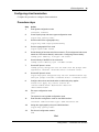
SIP configuration . . . . . . . . . . . . . . . . . . . . . . . . . . . . . . . . . . . . . . . . . . . . . . 35
Prerequisites to SIP configuration . . . . . . . . . . . . . . . . . . . . . . . . . . . . . . . . . . . . . . . . 35
Configuring SIP system settings . . . . . . . . . . . . . . . . . . . . . . . . . . . . . . . . . . . . . . 37
Configuring CAC . . . . . . . . . . . . . . . . . . . . . . . . . . . . . . . . . . . . . . . . . . . . . . . . . . 38
Configuring FXS/FXO global information . . . . . . . . . . . . . . . . . . . . . . . . . . . . . . . 39
Configuring FXS . . . . . . . . . . . . . . . . . . . . . . . . . . . . . . . . . . . . . . . . . . . . . . . . . . 40
Configuring FXO . . . . . . . . . . . . . . . . . . . . . . . . . . . . . . . . . . . . . . . . . . . . . . . . . . 41
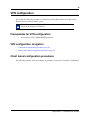
VPN configuration . . . . . . . . . . . . . . . . . . . . . . . . . . . . . . . . . . . . . . . . . . . . . 45
Prerequisites for VPN configuration . . . . . . . . . . . . . . . . . . . . . . . . . . . . . . . . . . . . . . 45
Client tunnel configuration procedures . . . . . . . . . . . . . . . . . . . . . . . . . . . . . . . . . . . . 45
Client tunnel configuration navigation . . . . . . . . . . . . . . . . . . . . . . . . . . . . . . . . . . 46
Configuring remote identity (client) . . . . . . . . . . . . . . . . . . . . . . . . . . . . . . . . . . . . 46
Configuring users . . . . . . . . . . . . . . . . . . . . . . . . . . . . . . . . . . . . . . . . . . . . . . . . . 47
Configuring the address pool . . . . . . . . . . . . . . . . . . . . . . . . . . . . . . . . . . . . . . . . 48
Configuring client termination . . . . . . . . . . . . . . . . . . . . . . . . . . . . . . . . . . . . . . . . 49
Enabling VPN (client) . . . . . . . . . . . . . . . . . . . . . . . . . . . . . . . . . . . . . . . . . . . . . . 50
Branch office tunnel configuration procedures . . . . . . . . . . . . . . . . . . . . . . . . . . . . . . 52
Branch office tunnel configuration navigation . . . . . . . . . . . . . . . . . . . . . . . . . . . . 52
Configuring remote identity (branch office) . . . . . . . . . . . . . . . . . . . . . . . . . . . . . . 52
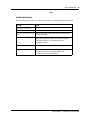
The following table describes the variables and values for configuring VPN global settings. 53
Configuring IKE . . . . . . . . . . . . . . . . . . . . . . . . . . . . . . . . . . . . . . . . . . . . . . . . . . . 53
Enabling VPN (branch office) . . . . . . . . . . . . . . . . . . . . . . . . . . . . . . . . . . . . . . . . 55
QoS configuration . . . . . . . . . . . . . . . . . . . . . . . . . . . . . . . . . . . . . . . . . . . . . 57
Prerequisites for QoS configuration . . . . . . . . . . . . . . . . . . . . . . . . . . . . . . . . . . . . . . . 57
QoS configuration procedures . . . . . . . . . . . . . . . . . . . . . . . . . . . . . . . . . . . . . . . . . . . 57
QoS configuration navigation . . . . . . . . . . . . . . . . . . . . . . . . . . . . . . . . . . . . . . . . 58
Configuring the uplink rate limit . . . . . . . . . . . . . . . . . . . . . . . . . . . . . . . . . . . . . . . 59
Configuring a policy map . . . . . . . . . . . . . . . . . . . . . . . . . . . . . . . . . . . . . . . . . . . . 59
Configuring a class map . . . . . . . . . . . . . . . . . . . . . . . . . . . . . . . . . . . . . . . . . . . . 60
Configuring QoS marking . . . . . . . . . . . . . . . . . . . . . . . . . . . . . . . . . . . . . . . . . . . 61
Configuring port-based QoS . . . . . . . . . . . . . . . . . . . . . . . . . . . . . . . . . . . . . . . . . 62
Configuring queue settings . . . . . . . . . . . . . . . . . . . . . . . . . . . . . . . . . . . . . . . . . . 63
NN47928-501
5
How to Get Help
This section explains how to get help for Nortel products and services.
Getting Help from the Nortel Web site
The best way to get technical support for Nortel products is from the Nortel Technical Support
Web site:
http://www.nortel.com/support
This site provides quick access to software, documentation, bulletins, and tools to address issues
with Nortel products. More specifically, the site enables you to:
•
download software, documentation, and product bulletins
•
search the Technical Support Web site and the Nortel Knowledge Base for answers to
technical issues
•
sign up for automatic notification of new software and documentation for Nortel equipment
•
open and manage technical support cases
Getting Help over the phone from a Nortel Solutions Center
If you don’t find the information you require on the Nortel Technical Support Web site, and have a
Nortel support contract, you can also get help over the phone from a Nortel Solutions Center.
In North America, call 1-800-4NORTEL (1-800-466-7835).
Outside North America, go to the following Web site to obtain the phone number for your region:
http://www.nortel.com/callus
Getting Help from a specialist by using an Express Routing
Code
To access some Nortel Technical Solutions Centers, you can use an Express Routing Code (ERC)
to quickly route your call to a specialist in your Nortel product or service. To locate the ERC for
your product or service, go to:
http://www.nortel.com/erc
Configuration — Command Line Interface
6
How to Get Help
Getting Help through a Nortel distributor or reseller
If you purchased a service contract for your Nortel product from a distributor or authorized
reseller, contact the technical support staff for that distributor or reseller.
NN47928-501
7
Introduction
This document describes how to configure the Business Service Gateway (BSG) using the Web
user interface.
Navigation
•
•
•
•
•
•
WAN configuration (page 9)
VLAN configuration (page 25)
Wireless network configuration (page 31)
SIP configuration (page 35)
VPN configuration (page 45)
QoS configuration (page 57)
Configuration — Command Line Interface
8
Introduction
NN47928-501
9
WAN configuration
This section describes the procedures to configure the Wide Area Network (WAN) setup for the
Business Services Gateway (BSG) system.
WAN configuration navigation
•
•
•
Ethernet (page 9)
DSL (page 16)
T1/E1 (page 19)
Ethernet
This section describes Ethernet configuration. Ethernet appears under WAN configuration if you
are connected to a BSG8ew or BSG12ew.
Ethernet navigation
•
•
Ethernet WAN configuration (page 9)
PPPoE WAN configuration (page 12)
Ethernet WAN configuration
This section describes Ethernet WAN configuration.
Prerequisites for Ethernet WAN configuration
•
You must have SYSTEM - READ WRITE permission.
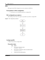
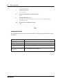
Ethernet WAN configuration procedures
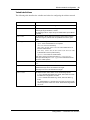
The following task flow shows the sequence of procedures to perform to configure the Ethernet
WAN.
Configuration — Command Line Interface
10
WAN configuration
Figure 1 Ethernet WAN configuration procedures
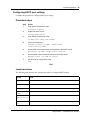
Configuring the Ethernet WAN
Complete this procedure to configure the Ethernet WAN.
Prerequisites
•
Access the box through an interface other than the WAN as this procedure will take down the
WAN.
Procedure steps
Step
Action
1
Enter global configuration mode:
configure terminal
2
Enter interface configuration mode on the WAN interface:
interface fastethernet 0/12
3
Disable the physical interface:
shutdown
4
Remove any configured IP address:
no ip address
5
Set the IP address of the WAN interface:
ip address <wan-ip-address> <subnet-mask>
6
Enable the interface:
no shutdown
NN47928-501
WAN configuration
7
11
Exit interface configuration mode.
exit
The system is now in global configuration mode.
8
Add a default route:
ip route 0.0.0.0 0.0.0.0 <ip-address-of-router> 1
9
Assign the addresses of the DNS servers:
dns-server forwarder primary <ip-addr-of-primary-dns>
secondary <ip-addr-of-secondary-dns>
10
Exit all levels of configuration mode:
end
End
Variable definitions
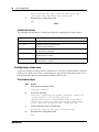
The following table describes the variables and values for configuring Ethernet WAN.
Variable
Value
wan-ip-address
Type the WAN IP address, if the IP Address Assignment is manual.
subnet-mask
Type the subnet mask, if the IP Address Assignment is manual.
ip-address-of-router Type the gateway IP Address, if the IP Address Assignment is manual.
ip-addr-of-primary-d Type the primary DNS server IP address, if the IP Address Assignment is
manual.
ns
ip-addr-of-secondary Type the secondary DNS server IP address, if the IP Address Assignment
is manual.
-dns
Configuring the uplink rate limit
Complete this procedure to configure the uplink rate limit. This procedure is optional for
the Ethernet WAN.
Procedure steps
Step
Action
1
Enter global configuration mode:
configure terminal
2
Set the uplink rate limit speed:
uplink rate limit <speed-in-bps>
3
Enable the uplink rate limit:
uplink rate limit enable
Configuration — Command Line Interface
12
WAN configuration
4
Exit all levels of configuration mode:
end
End
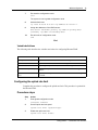
Variable definitions
The following table describes the variables and values for configuring the uplink rate limit.
Variable
Value
speed-in-bps
Specifies the uplink rate limit over the WAN interface (in bps).
The range is 100,000 to 100,000,000 bps.
PPPoE WAN configuration
This section describes PPPoE WAN configuration.
Prerequisites for WAN configuration
•
You must have SYSTEM - READ WRITE permission.
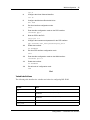
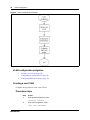
PPPoE WAN configuration procedures
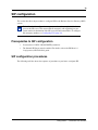
The following task flow shows the sequence of procedures to perform to configure the PPPoE
WAN.
NN47928-501
WAN configuration
13
Figure 2 PPPoE WAN configuration procedures
Configuring the PPPoE WAN
Complete this procedure to configure the PPPoE WAN.
Prerequisites
•
Access the box through an interface other than the WAN because this procedure closes down
the WAN.
Procedure steps
Step
Action
1
Enter global configuration mode:
configure terminal
2
Enter interface configuration mode on the WAN interface:
interface fastethernet 0/12
3
Disable the physical interface:
shutdown
4
Exit from interface configuration mode:
exit
The system is now in global configuration mode.
5
Enter interface configuration mode on the PPP interface:
interface ppp 1
6
Attach a PPP link to a physical ethernet:
layer fastethernet 0/12
7
Configure the PPP interface with the username and password:
Configuration — Command Line Interface
14
WAN configuration
ppp username <username> password <password>
8
Enable the interface:
no shutdown
9
Exit from PPP interface configuration mode:
exit
The system is now in global configuration mode.
10
Enter interface configuration mode on the WAN interface:
interface fastethernet 0/9
11
Enable the interface:
no shutdown
12
Exit all levels of configuration mode:
end
End
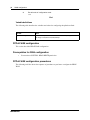
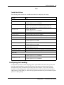
Variable definitions
The following table describes the variables and values for configuring PPPoE WAN.
Variable
Value
username
The PPPoE user name.
password
The PPPoE password.
hostname-of-BSG
The BSG host name.
Configuring the uplink rate limit
Complete this procedure to configure the uplink rate limit. Only limit the uplink speed if
your WAN bandwidth is less than 100Base-T.
Procedure steps
Step
Action
1
Enter global configuration mode:
configure terminal
2
Set the uplink rate limit speed:
uplink rate limit <speed-in-bps>
3
Enable the uplink rate limit:
uplink rate limit enable
4
NN47928-501
Exit all levels of configuration mode:
WAN configuration
15
end
End
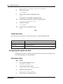
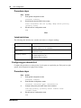
Variable definitions
The following table describes the variables and values for configuring the uplink rate limit.
Variable
Value
speed-in-bps
Specifies the uplink rate limit over the WAN interface (in bps).
The range is 100,000 to 100,000,000 bps.
Configuration — Command Line Interface
16
WAN configuration
DSL
DSL appears under WAN configuration if you are connected to a BSG12aw.
Prerequisites for DSL configuration
•
You must have access read/write permission to configure DSL.
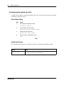
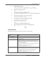
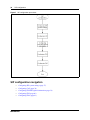
DSL configuration procedures
The following task flow shows the sequence of procedures to perform to configure DSL.
Figure 3 DSL configuration procedures
Configuring DSL
Complete this procedure to configure DSL.
Procedure steps
Step
Action
1
Enter global configuration mode:
configure terminal
2
Enter interface configuration mode on the WAN interface:
interface pvc 1/1
3
NN47928-501
Configure the Virtual Path Identifier:
WAN configuration
17
vpi 0
4
Configure the Virtual Channel Identifier:
vci 35
5
Configure the Maximum Receivable Units:
mru 1492
6
Exit from interface configuration mode:
exit
7
Enter interface configuration mode on the PPP interface:
interface ppp 1
8
Bind the PPP to the PVC:
layer pvc 1/1
9
Configure the username and password for the PPP interface:
ppp username user_name password pass_word
10
Enable the interface:
no shutdown
11
Exit from PPP interface configuration mode:
exit
12
Enter interface configuration mode on the WAN interface:
interface pvc 1/1
13
Enable the interface:
no shutdown
14
Exit all levels of configuration mode:
end
End
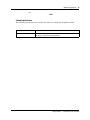
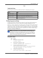
Variable definitions
The following table describes the variables and values for configuring DSL WAN.
Variable
Value
mru
The Maximum Receivable Unit (MRU) value.
vpi
The Virtual Path Identifier (VPI) used by the DSL modem to make a
connection.
vci
The Virtual Channel Identifier (VCI) used by the DSL modem to make a
connection.
user_name
The user name for the specified PPP interface, used for authentication.
pass_word
The password for the specified PPP interface, used for authentication.
Configuration — Command Line Interface
18
WAN configuration
Configuring the uplink rate limit
Complete this procedure to enable the uplink rate limit. The rate limit value is based on the uplink
bandwidth of the ADSL service.
Procedure steps
Step
Action
1
Enter global configuration mode:
configure terminal
2
Set the uplink rate limit speed:
uplink rate limit <speed-in-bps>
3
Enable the uplink rate limit:
uplink rate limit enable
4
Exit all levels of configuration mode:
end
End
Variable definitions
The following table describes the variables and values for configuring the uplink rate limit.
Variable
Value
speed-in-bps
Specifies the uplink rate limit over the WAN interface (in bps).
The range is 100,000 to 100,000,000 bps.
NN47928-501
WAN configuration
19
T1/E1
T1/E1 appears under WAN configuration if you are connected to a BSG12tw.
Prerequisites for T1/E1 configuration
•
You must have access read/write permission to configure T1/E1.
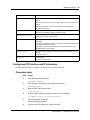
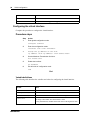
T1/E1 configuration procedures
The following task flow shows the sequence of procedures to perform to configure T1/E1.
Figure 4 T1/E1 configuration procedures
Configuring the T1 interface
Complete this procedure to configure the T1 interface.
This procedure guides you through setting up one T1 interface.
Configuration — Command Line Interface
20
WAN configuration
Procedure steps
Step
Action
1
Enter global configuration mode:
configure terminal
2
Enter interface configuration mode on the T1 interface:
controller t1 1
3
Configure framing:
framing {esf|sf}
4
Configure line code:
linecode b8zs
5
Configure line mode:
mode {csu|dsu}
6
Configure long cablelength (if mode is csu):
cablelength long {neg225db|neg15db|neg75db|zerodb}
7
Configure short cablelength (if mode is dsu):
cablelength short {133|266|399|533|655}
8
Configure clock source:
clock source {local|loop}
9
Configure channel group index and time slots:
channel-group 1 timeslots 1-24
10
Exit all levels of configuration mode:
end
End
Variable definitions
The following table describes the variables and values for configuring T1 WAN.
Variable
Value
framing
The framing type for the T1 data line.
Options for T1:
Extended Super Frame (ESF)— 24 consecutive 193-bit frames of data.
Super Frame (SF)—12 consecutive 193-bits of data.
The default value is ESF.
linecode
binary eight zero substitution (bz8s)
NN47928-501
WAN configuration
21
Variable
Value
mode
The line mode.
Options:
channel service unit (csu)—select if cable length is equal to or more than
655 feet.
data service unit (dsu)—select if cable length is less than 655 feet.
The default value is csu.
cablelength long
Cable length options (if mode is csu).
Options are: neg225db, neg15db, neg75db, zerodb.
cablelength short
Cable length options (if mode is dsu).
Options are: 133, 266, 399, 533, 655
clock source
The clock source.
Options are:
Local Timing - A local clock source is used or an external clock is attached
to the box containing the interface.
Loop Timing - Recovered received clock is used to transmit the clock.
The default value is Loop Timing.
channel-group
The channel group index. This identifies a grouping of channels on the T1
interface.
The range is 1to 64.
timeslots
The time slots.
The range is 1to 24 for T1.
Configuring the E1 interface
Complete this procedure to configure the E1 interface.
This procedure guides you through setting up one E1 interface.
Procedure steps
Step
Action
1
Enter global configuration mode:
configure terminal
2
Enter e1 mode:
controller mode e1
Warning: Mode change takes effect after you reboot the BSG.
3
Exit all levels of configuration mode:
end
4
Save changes:
Configuration — Command Line Interface
22
WAN configuration
write startup-config
5
Reboot the BSG:
reload
6
Enter global configuration mode:
configure terminal
7
Enter interface configuration mode on the E1 interface:
controller e1 1
8
Configure framing:
framing {e1|e1crc}
9
Configure line code:
linecode b8zs
10
Configure line mode:
mode {csu|dsu}
11
Configure long cablelength (if mode is csu):
cablelength long {neg225db|neg15db|neg75db|zerodb}
12
Configure short cablelength (if mode is dsu):
cablelength short {133|266|399|533|655}
13
Configure clock source:
clock source {local|loop}
14
Configure channel group index and time slots:
channel-group 1 timeslots 1-24
15
Exit all levels of configuration mode:
end
End
Variable definitions
The following table describes the variables and values for configuring E1 WAN.
Variable
Value
framing
The framing type for the E1 data line.
Options for E1:
E1 - a single E1 frame consists of 256 bits, grouped into 32 octets or time
slots. The timeslots are numbered 0 to 31.
E1CRC
The default value is E1CRC.
linecode
binary eight zero substitution (bz8s)
NN47928-501
WAN configuration
23
Variable
Value
mode
The line mode.
Options:
channel service unit (csu)—select if cable length is equal to or more than
655 feet.
data service unit (dsu)—select if cable length is less than 655 feet.
The default value is csu.
cablelength long
Cable length options (if mode is csu).
Options are: neg225db, neg15db, neg75db, zerodb.
cablelength short
Cable length options (if mode is dsu).
Options are: 133, 266, 399, 533, 655
clock source
The clock source.
Options are:
Local Timing - A local clock source is used or an external clock is attached
to the box containing the interface.
Loop Timing - Recovered received clock is used to transmit the clock.
The default value is Loop Timing.
channel-group
The channel group index. This identifies a grouping of channels on the E1
interface.
The range is 1to 64.
timeslots
The time slots.
The range is 2 to 32 for E1.
Configuring PPP interface and IP information
Complete this procedure to configure the PPP interface and IP information.
Procedure steps
Step
Action
1
Enter global configuration mode:
configure terminal
2
Enter interface configuration mode on the PPP interface:
interface ppp 1
3
Bind the PPP to the serial interface:
layer serial 1/1
4
Configure the ip address and subnet mask for the PPP interface:
ip address 47.129.66.70 255.255.255.0
5
Configure the peer IP address:
peer ip address <ip address>
6
Configure the PPP interface as a public interface:
Configuration — Command Line Interface
24
WAN configuration
no private link
7
Enable the interface:
no shutdown
8
Exit from PPP interface configuration mode:
exit
9
Configure the DNS server:
dns-server forwarder primary 47.129.66.100 secondary
47.129.66.101
10
Exit all levels of configuration mode:
end
End
Variable definitions
The following table describes the variables and values for configuring the PPP interface and IP
information.
Variable
Value
ip address
The IP address of the PPP interface.
subnet mask
The subnet mask of the IP address.
DNS server forwarder
primary
The primary DNS server IP address.
DNS server forwarder
secondary
The secondary DNS server IP address.
NN47928-501
25
VLAN configuration
This section describes the procedures for configuring the virtual local area network (VLAN)
settings for the Business Service Gateway (BSG).
VLAN1 is the default VLAN. The BSG provides VLAN1 as a fully functioning VLAN using all
eight ports.
Prerequisites to VLAN configuration
•
You must have SYSTEM - READ WRITE, L2 - READ WRITE, and L3 - READ WRITE
permission to access the information on the VLAN configuration panels.
VLAN configuration procedures
The following task flow shows the sequence of procedures to perform to configure a VLAN.
Configuration — Command Line Interface
26
VLAN configuration
Figure 5 VLAN configuration procedures
VLAN configuration navigation
•
•
•
Creating a new VLAN (page 26)
Configuring the virtual interface (page 28)
Configuring DHCP pool settings (page 29)
Creating a new VLAN
Complete this procedure to create a new VLAN.
Procedure steps
Step
Action
1
Enter global configuration mode:
configure terminal
2
Enter vlan configuration mode:
vlan <vlan-id-number>
NN47928-501
VLAN configuration
3
27
Assign the ports to the vlan:
ports <interface-type> <tagged-port(s)> untagged
<interface-type> <untagged-port(s)> name <vlan-name>
4
Exit from vlan configuration mode:
exit
The system is now in global configuration mode.
5
For each one of the interface ports in the ports command, do steps 6 through
8.
6
Enter interface configuration mode on the interface port.
interface fastethernet <port>
7
For this interface, assign the specified port to the VLAN:
switchport pvid <vlan-id-number>
8
Exit the interface configuration mode:
exit
The system is now in global configuration mode.
9
After configuring all ports, exit all levels of configuration mode:
end
End
Variable definitions
The following table describes the variables and values for creating a VLAN.
Variable
Value
vlan-id-number
A unique VLAN ID that you want to configure as a static VLAN.
interface-type
The type of port. Valid values are fastethernet and
gigbitethernet
tagged-port(s)
The member port number list for a VLAN.
Member ports represent the set of ports permanently assigned to the
VLAN egress list. Frames that belong to the specified VLAN are forwarded
on the ports in the egress list.
Enter a comma separated list of ports or port ranges. For example, 0/1-6,
0/11.
Valid values for fastethernet are 0/1 to 0/6
Valid values for gigabitethernet are 0/7 to 0/8
untagged-port(s)
The untagged port number list for a VLAN.
Enter a comma separated list of ports or port ranges. For example, 0/1-6,
0/11.
The Untagged Ports list must be a subset of the Member Ports.
Valid values for fastethernet are 0/1 to 0/6
Valid values for gigabitethernet are 0/7 to 0/8
Configuration — Command Line Interface
28
VLAN configuration
Variable
Value
vlan-name
The VLAN name.
port
The port number of a tagged or untagged port.
Configuring the virtual interface
Complete this procedure to configure the virtual interface.
Procedure steps
Step
Action
1
Enter global configuration mode:
configure terminal
2
Enter vlan configuration mode:
interface vlan <vlan-id-number>
3
Assign the ip address of the vlan:
ip address <vlan-ip-address> <vlan-subnet-mask>
4
Set the Maximum Transmission Unit size:
mtu <frame-size>
5
Enable the interface:
no shutdown
6
Exit all levels of configuration mode:
end
End
Variable definitions
The following table describes the variables and values for configuring the virtual interface.
Variable
Value
vlan-id-number
The VLAN identifier.
vlan-ip-address
The IP address, if the IP address assignment is Manual.
vlan-subnet-mask
The subnet mask for the LAN, if the IP address assignment is Manual.
frame-size
The Maximum Transmission Unit value.
The range is 90 to 9902. The default value is 1500.
If using Fast Ethernet, the MTU frame size must not be larger than 1522.
NN47928-501
VLAN configuration
29
Configuring DHCP pool settings
Complete this procedure to configure DHCP pool settings.
Procedure steps
Step
Action
1
Enter global configuration mode:
configure terminal
2
Enable the DHCP server:
service dhcp-server
3
Enter DHCP configuration mode:
ip dhcp pool <dhcp-pool-number>
4
Set the pool addresses:
network <network-ip-addr> <subnet-mask>
<end-of-pool-ip-addr>
5
Set the DNS server address that will be passed to the DHCP clients:
dns-server <ip-addr-of-dns-server-for-pool>
6
Set the default router that will be passed to the DHCP clients:
default-router <ip-addr-of-router>
7
Exit all levels of configuration mode:
end
End
Variable definitions
The following table describes the variables and values to configure DHCP settings.
Variable
Value
dhcp-pool-numb The pool ID for the DHCP pool.
er
network-ip-add The subnet of the IP address in the pool.
r
subnet-mask
The subnet mask of the IP address in the pool.
end-of-pool-ip The last IP address in the pool.
-addr
ip-addr-of-dns The IP address of the DNS server that will be passed to the DHCP clients.
-server-for-po
ol
ip-addr-of-rou The IP address of the default router that will be passed to the DHCP clients.
ter
Configuration — Command Line Interface
30
VLAN configuration
NN47928-501
31
Wireless network configuration
This section describes the procedures to configure the wireless network for the Business Services
Gateway (BSG) system.
Prerequisites to wireless network configuration
•
•
•
You must have WIRELESS - READ WRITE permission.
You must configure DHCP pool settings for the VLAN used for the wireless network.
You must configure the radio port as a member port of the VLAN used for the wireless
network.
Wireless network configuration procedures
The following task flow shows the sequence of procedures to perform to configure a wireless
network.
Figure 6 Wireless network configuration procedures
Configuring a wireless network
Complete this procedure to configure a wireless network.
Note: WLAN 1 exists by default and the SSID cannot be changed. WLAN 1 can be deleted and
recreated with a different SSID.
Configuration — Command Line Interface
32
Wireless network configuration
Procedure steps
Step
Action
1
Enter global configuration mode:
configure terminal
2
Create a wireless LAN:
config wlan create <wlan-id> <SSID>
3
Tie the WLAN to the VLAN:
config wlan interface <wlan-id> <vlan-name>
4
Set the WLAN authorization type
config wlan security auth-type <auth-type> <wlan-id>
5
Configure the authorization key:
config wlan security pre-shared-key <wlan-id> <key-format>
<key>
6
Enable the WLAN:
config wlan enable <wlan-id>
7
Set the country code. The radio must be disabled before you set the country
code:
config ap country us
Warning: Setting the incorrect region can result in the violation of applicable
law.
8
Enter radio interface configuration mode:
interface radio 1/1
9
Set the radio mode:
config dot11 mode <radio-mode>
10
Turn on the radio. You must set the country code before you enable the radio:
config dot11 enable network
11
Exit all configuration modes:
end
End
NN47928-501
Wireless network configuration
33
Variable definitions
The following table describes the variables and values for configuring the wireless network.
Variable
Value
wlan-id
The ID number of the WLAN. Range is 1 to 4.
SSID
The SSID is alphanumeric and is mapped to the VLAN ID.
SSID length ranges between 1 and 32.
The mapping must be unique. Only one SSID number per VLAN ID
is allowed.
vlan-name
The VLAN ID to which SSID users belong. Access points use this
VLAN ID to tag the packets from the specified users of the given
SSID.
auth-type
The authorization types are:
• open - use if authentication is not required.
• shared - use for a shared key.
• WPA, WPA2, or WPA-WPA2-Mixed- Use if Radius server is
used for authentication.
• WPA-PSK, WPA2-PSK, or WPA-WPA2-PSK-Mixed -- Use
if authentication uses a preshared key.
• open1x - use for 802.1x authentication.
Note: Step 5 of this procedure specifies pre-shared-key.
When pre-shared-key the auth-type in this command must be
one of the “-PSK” options.
key-format
The format of the authorization key. The values are either ascii or
hex.
key
The authorization key.
Hexadecimal keys can be 64 characters in length.
ASCII keys can be 8 to 63 characters in length.
radio-mode
The required radio mode. Select one of the following options:
• b - For a network with all 802.11b clients, select 802.11b mode.
The BSG has a single 802.11b radio.
• g - For a network with all 802.11g clients, select the 802.11g
mode.
• bg - Mixed Mode for a network with many 802.11g devices with
a lesser population of 802.11b clients. Performance degradation
can occur.
Configuration — Command Line Interface
34
Wireless network configuration
NN47928-501
35
SIP configuration
This section describes the procedures to configure SIP for the Business Services Gateway (BSG)
system.
Note: You should configure the emergency number (for example, 911) before
you use the SIP server. This ensures that an emergency call originating on your
system reaches its destination if the SIP server becomes unavailable. To configure
the emergency number, see Configuring FXO (page 41).
Prerequisites to SIP configuration
•
•
You must have VOICE - READ WRITE permission.
The Internal SIP Server must be enabled. For details, refer to the BSG8ew 1.0
Configuration (NN47928-500) guide.
SIP configuration procedures
The following task flow shows the sequence of procedures to perform to configure SIP.
Configuration — Command Line Interface
36
SIP configuration
Figure 7 SIP configuration procedures
SIP configuration navigation
•
•
•
•
•
Configuring SIP system settings (page 37)
Configuring CAC (page 38)
Configuring FXS/FXO global information (page 39)
Configuring FXS (page 40)
Configuring FXO (page 41)
NN47928-501
SIP configuration
37
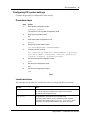
Configuring SIP system settings
Complete this procedure to configure SIP system settings.
Procedure steps
Step
Action
1
Enter global configuration mode:
configure terminal
The system is now in global configuration mode.
2
Enter sip configuration mode:
sip
3
Enter sip domain configuration mode:
domain
4
Set the SIP server domain name:
set serverdomainname <SIPDomainName>
5
Configure the SIP settings:
set sipserver PolledServers Pollingaddress <sip-server>
port <port-number> pollinterval <interval> pollretries
<retries> transport <transport-protocol>
6
Exit from sip domain configuration mode
exit
7
Exit from sip configuration mode:
exit
8
Exit from all configuration modes:
end
End
Variable definitions
The following table describes the variables and values for configuring SIP system settings.
Variable
Value
SIPDomainName
The domain name of the SIP server.
You can also type the IP address of the SIP server in this field.
The default name is mydomain.com.
sip-server
The ip address or hostname of the central SIP server.
If specifying the IP address, use the IP address for this argument.
If specifying the hostname, enter hostname <hostname> where
<hostname> is the fully qualified domain name of the SIP server.
Configuration — Command Line Interface
38
SIP configuration
Variable
Value
port-number
The port number for the transport protocol. Values range from 1to 65535.
The default value is 5060
interval
The polling interval in seconds. Enter a number between 10 and 600.
The default value is 30 seconds.
retries
The number of polling retries. Values range from 1 to 10.
The default value is 2.
transport-protocol
Select the required transport protocol for SIP. Select one of the following
options:
• udp - User Datagram Protocol
• tcp - Transmission Control Protocol
• tls - Transport Layer Security
The default value is UDP.
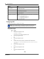
Configuring CAC
Complete this procedure to configure CAC settings.
Note: If the maximum number of simultaneous SIP calls across the WAN is
reached, the next SIP call attempt fails and the caller hears fast busy tone.
Procedure steps
Step
Action
1
Enter global configuration mode:
configure terminal
The system is now in global configuration mode.
2
Enter sip configuration mode:
sip
3
Enter bsg configuration mode:
bsg
4
Configure the maximum number of simultaneous SIP calls allowed:
set sipserver MaximumSimWANCallsAllowed <WAN-interface>
<MaxCalls>
5
Exit from bsg configuration mode
exit
6
Exit from sip configuration mode:
exit
7
Exit from all configuration modes:
end
End
NN47928-501
SIP configuration
39
Variable definitions
The following table describes the variables and values for configuring CAC settings.
Variable
Value
WAN-interface
Specifies the WAN interface. Valid values are:
Fa0/9 - for a direct ethernet connection
ppp1 - when using DSL
MaxCalls
Type the maximum simultaneous calls allowed on the WAN link.
The range is from 1 to 100.
The default value for BSG8ew is 50.
The default value for BSG12ew/aw/tw is 100.
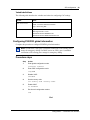
Configuring FXS/FXO global information
Complete this procedure to configure FXS/FXO global information.
Note: For BSG8ew, FXS2 (port 2) maintains connection to FXO during power
outage for emergency dialing. For BSG12ew/aw/tw, FXS1 (port 1) maintains
connection to FXO during power outage for emergency dialing.
Procedure steps
Step
Action
1
Enter global configuration mode:
configure terminal
2
Enter VOIP configuration mode:
voip1000
3
Disable VOIP:
shutdown
4
Set the country code:
set country code <country-code>
5
Enable VOIP:
no shutdown
6
Exit from all configuration modes:
end
End
Configuration — Command Line Interface
40
SIP configuration
Variable
Value
country-code
Valid options are:
us | uk | japan | china | india | germany |
south-africa | korea | brazil | australia
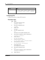
Configuring FXS
Complete this procedure to configure FXS information.
Procedure steps
Step
Action
1
Enter global configuration mode:
configure terminal
2
Enter VOIP configuration mode:
voip1000
3
Disable VOIP:
shutdown
4
Exit VOIP configuration mode:
exit
The system is now in global configuration mode.
5
Enter interface configuration mode on FXS channel 1:
interface fxs channel 1
6
Enable FXS line 1:
set fxs line enable
7
Set phone number for FXS line 1:
set fxs channel-number <fxs-phone-number>
8
Set the password for FXS line 1:
set fxs password <fxs-password>
9
Set the display name:
set fxs display-name “John Doe”
10
Exit to global configuration mode:
exit
11
Enter interface configuration mode on FXS channel 2:
interface fxs channel 2
12
NN47928-501
Enable FXS line 2:
SIP configuration
41
set fxs line enable
13
Set phone number for FXS line 2:
set fxs channel-number <fxs-phone-number>
14
Set the display name:
set fxs display-name “John Doe”
15
Set the password for FXS line 2:
set fxs password <fxs-password>
16
Exit from interface configuration mode:
exit
17
Enter VOIP configuration mode:
voip1000
18
Enable VOIP:
no shutdown
19
Exit from all configuration modes:
end
End
Variable definitions
The following table describes the variables and values for configuring FXS information.
Variable
Value
fxs-phone-number
The phone number assigned to the line. This is the number
that will be dialed to access this phone.
The maximum length is 31 digits.
fxs-password
The password to access the FXS line.
The maximum length is 31 digits.
Configuring FXO
Complete this procedure to configure FXO information.
Note: Use this procedure to configure the emergency number. You should
configure the emergency number (for example, 911) before you use the SIP
server. This ensures that an emergency call originating on your system reaches its
destination if the SIP server becomes unavailable.
Configuration — Command Line Interface
42
SIP configuration
Procedure steps
Step
Action
1
Enter global configuration mode:
configure terminal
2
Enter VOIP configuration mode:
voip1000
3
Disable VOIP:
shutdown
4
Exit VOIP configuration mode:
exit
The system is now in global configuration mode.
5
Enter interface configuration mode on FXO channel 1:
interface fxo channel 1
6
Enable FXO line 1:
set pstn-gateway enable
7
Set phone number for FXO line 1:
set fxo channel-number <fxo-phone-number>
8
Set the password for FXO line 1:
set fxo password <fxo-password>
9
Set the forwarding number:
set fxo forward phone-no <fxo-forward-phone-number>
10
Set the maximum number of rings allowed:
set fxo ring count <max-number-rings>
11
Set the emergency number:
set fxo emergency-number <emergency-phone-number>
12
Set the on-hook detection time:
set fxo hook detect time <detect-time> milliseconds
13
Exit from interface configuration mode:
exit
14
Enter VOIP configuration mode:
voip1000
15
Enable VOIP:
no shutdown
16
Exit from all configuration modes:
end
NN47928-501
SIP configuration
43
End
Variable definitions
The following table describes the variables and values for configuring FXO information.
Variable
Value
fxo-phone-number
The phone number assigned to the line.
fxo-password
The password to access the FXO line.
fxo-forward-phone-nu
mber
Number to use when an incoming call on the FXO channel
requires forwarding.
max-number-rings
The ring count. This is the maximum number of rings within
which FXO must get an answer from the remote number.
The minimum value is 1 and maximum value is 6.
The default value is 2.
emergency-phone-numb
er
The emergency phone number to route emergency calls to.
detect-time
Type the on-hook detection time.
The value ranges from 100 to10000 milliseconds.
The default value is 2000 milliseconds.
Configuration — Command Line Interface
44
SIP configuration
NN47928-501
45
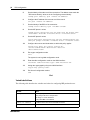
VPN configuration
This section describes the procedures to configure the Virtual Private Network (VPN) for the
Business Services Gateway (BSG) system.
Note: If you are connecting two BSG units at either end of the VPN tunnel,
ensure the IP addresses are different.
Prerequisites for VPN configuration
•
You must have VPN - READ WRITE permission.
VPN configuration navigation
•
•
Client tunnel configuration procedures (page 45)
Branch office tunnel configuration procedures (page 52)
Client tunnel configuration procedures
The following task flow shows the sequence of procedures to perform to configure a client tunnel.
Configuration — Command Line Interface
46
VPN configuration
Figure 8 Client tunnel configuration procedures
Client tunnel configuration navigation
•
•
•
•
•
Configuring remote identity (client) (page 46)
Configuring users (page 47)
Configuring the address pool (page 48)
Configuring client termination (page 49)
Enabling VPN (client) (page 50)
Configuring remote identity (client)
Complete the following procedure to configure the remote identity.
Procedure steps
Step
NN47928-501
Action
VPN configuration
1
47
Enter global configuration mode:
configure terminal
2
Assign a VPN remote identity:
vpn remote identity <identity-type> <identity-value> psk
<preshared-key>
3
Exit from all configuration modes:
end
End
Variable definitions
The following table describes the variables and values for configuring VPN global settings.
Variable
Value
identity-type
The user identity type that uniquely identifies the peer. Select one of the
following:
• IPV4 - specifies the IP address
• FQDN- specifies the fully qualified domain name (an unambiguous
domain name that denotes the position of the node in the DNS tree
hierarchy)
• EMAIL - specifies the email of the peer
• KEYID - specifies the string that uniquely identifies the peer
identity-value
The value corresponding to the selected Remote Identity Type.
preshared-key
A string of text which is the key that VPN uses to authenticate
before receiving any other credentials.
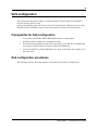
Configuring users
Complete the following procedure for each remote user.
Procedure steps
Step
Action
1
Enter global configuration mode:
configure terminal
2
For each user, create a user name and password:
ra-vpn username <username> password <password>
3
Exit from all configuration modes:
end
End
Configuration — Command Line Interface
48
VPN configuration
Variable definitions
The following table describes the variables and values for configuring the user database.
Variable
Value
username
The user name.
The range is 1 to 31 characters.
password
The password for the user.
The range is 1 to 31 characters.
Configuring the address pool
Complete this procedure to configure the address pool.
Prerequisites
Note: The address pool cannot be in the same subnet as DHCP addresses.
Procedure steps
Step
Action
1
Enter global configuration mode:
configure terminal
2
Configure the address pool for incoming VPN connections:
ip ra-vpn pool <poolname> <start_ip-end_ip>
3
Exit from all configuration modes:
end
End
Variable definitions
The following table describes the variables and values for configuring the VPN address pool.
Variable
Value
poolname
The name of the address pool. Addresses within the pool are allocated to
remote users when they make VPN connection requests.
start_ip
The first IP address of the pool.
end_ip
The last IP address of the pool.
NN47928-501
VPN configuration
49
Configuring client termination
Complete this procedure to configure client termination.
Procedure steps
Step
Action
1
Enter global configuration mode:
configure terminal
2
Create a policy map and enter crypto configuration mode
crypto map <policy-name>
3
Set the mode for the cryptographic key
crypto key mode ravpn-preshared-key
4
Set the cryptographic IPsec mode
crypto ipsec mode tunnel
5
Set the identity of the other end of the connection. The local type and value must
match the "VPN remote identity" values set in ‘Configuring remote identity’:
isakmp peer identity <id-type> <id-value>
6
Set the identity of the BSG of the connection
isakmp local identity ipv4 <IP-addr-of-BSG>
7
Set the IKE phase 1 values
isakmp policy encryption aes-192 hash sha1 dh group5 exch
aggressive lifetime <lifetime-units> <lifetime-value>
8
Set the IKE phase 2 values
crypto map ipsec encryption esp aes-192 authentication esp
sha1 pfs group5 lifetime <lifetime-units> <lifetime-value>
9
Configure the sources and destinations to which this policy applies
access-list apply any source <source-IP>
<source-subnet-mask> destination <dest-IP>
<dest-subnet-mask>
10
Exit crpto configuration mode:
exit
The system is now in global configuration mode.
11
Enter interface configuration mode on the WAN interface:
interface <WAN-interface-type> <WAN-interface-id>
12
Assign the cryptographic policy to the WAN interface:
crypto map <policy-name>
13
Exit from all configuration modes:
end
End
Configuration — Command Line Interface
50
VPN configuration
Variable definitions
The following table describes the variables and values for configuring client termination.
Variable
Value
policy-name
A IPsec policy name.
Each policy must have a unique name.
The range is 1 to 63 characters.
Policy name ALL is not allowed.
id-type
The id-type has to match an id type that was set in the remote identity.
The valid values are:
• IPV4 - IP address
• FQDN - Fully Qualified Domain Name
• EMAIL - email address of the user
• KEYID - uniquely identifies the peer
id-value
The id-value has to match the id-value set in the remote identity.
IP-addr-of-BSG
The IP address of this BSG.
lifetime-units
The life time unit. Valid values are secs | mins | hrs
lifetime-value
The life time value.
The range is 5 minutes to 8 hours.
source-IP
The Source IP address of the outbound traffic.
source-subnet-mask
The Network mask of the outbound traffic.
dest-IP
The Destination IP address of the outbound traffic.
dest-subnet-mask
The Destination mask of the outbound traffic.
WAN-interface-type
The valid values are:
ppp - use for DSL
fastethernet - use for direct connection to ethernet or cable modem
WAN-interface-id
The valid values are:
1 - use for DSL
0/9 - user for direct connection to ethernet or cable modem
Enabling VPN (client)
Complete this procedure to enable VPN.
Procedure steps
Step
Action
1
Enter global configuration mode:
configure terminal
2
NN47928-501
Enable VPN:
VPN configuration
51
set vpn enable
3
Exit from all configuration modes:
end
End
Configuration — Command Line Interface
52
VPN configuration
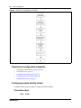
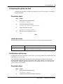
Branch office tunnel configuration procedures
The following task flow shows the sequence of procedures to configure a branch office tunnel.
Figure 9 Branch office tunnel configuration procedures
Branch office tunnel configuration navigation
•
•
•
Configuring remote identity (branch office) (page 52)
Configuring IKE (page 53)
Enabling VPN (branch office) (page 55)
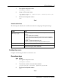
Configuring remote identity (branch office)
Complete the following procedure to configure the remote identity.
Procedure steps
Step
Action
1
Enter global configuration mode:
configure terminal
2
Assign a VPN remote identity:
vpn remote identity <identity-type> <identity-value> psk
<preshared-key>
NN47928-501
VPN configuration
3
53
Exit from all configuration modes:
end
End
Variable definitions
The following table describes the variables and values for configuring VPN global settings.
Variable
Value
identity-type
The user identity type that uniquely identifies the peer. Select one of the
following:
• IPV4 - specifies the IP address
• FQDN- specifies the fully qualified domain name (an unambiguous
domain name that denotes the position of the node in the DNS tree
hierarchy)
• EMAIL - specifies the email of the peer
• KEYID - specifies the string that uniquely identifies the peer
identity-value
The value corresponding to the selected Remote Identity Type.
preshared-key
A string of text which is the key that VPN uses to authenticate
before receiving any other credentials.
Configuring IKE
Complete the following procedure to configure the IKE pre-shared secret.
Prerequisites
•
Before you modify a policy, you must set the Policy Status to INACTIVE.
Procedure steps
Step
Action
1
Enter global configuration mode:
configure terminal
2
Create a policy map and enter crypto configuration mode
crypto map <policy-name>
3
Set the mode for the cryptographic key
crypto key mode preshared-key
4
Set the cryptographic IPsec mode
crypto ipsec mode tunnel
Configuration — Command Line Interface
54
VPN configuration
5
Set the identity of the other end of the connection. The address must match the
"VPN remote identity" value set in the ‘Configuring remote identity’:
isakmp peer identity ipv4 <remote-IP-address>
6
Configure the IP address of the remote end of the tunnel:
set peer <remote-IP-address>
7
Set the identity of the BSG of the connection:
isakmp local identity ipv4 <IP-addr-of-BSG>
8
Set the IKE phase 1 values
isakmp policy encryption aes-192 hash sha1 dh group5 exch
<exch-mode> lifetime <lifetime-units> <lifetime-value>
9
Set the IKE phase 2 values
crypto map ipsec encryption esp aes-192 authentication esp
sha1 pfs group5 lifetime <lifetime-units> <lifetime-value>
10
Configure the sources and destinations to which this policy applies
access-list apply any source <source-IP>
<source-subnet-mask> destination <dest-IP>
<dest-subnet-mask>
11
Exit crypto configuration mode:
exit
The system is now in global configuration mode.
12
Enter interface configuration mode on the WAN interface:
interface <WAN-interface-type> <WAN-interface-id>
13
Assign the cryptographic policy to the WAN interface:
crypto map <policy-name>
14
Exit from all configuration modes:
end
End
Variable definitions
The following table describes the variables and values for configuring IKE preshared secret.
Variable
Value
policy-name
A IPsec policy name.
Each policy must have a unique name.
The range is 1 to 63 characters.
Policy name ALL is not allowed.
remote-IP-address
IP address of the other end of the VPN connection.
IP-addr-of-BSG
The IP address of this BSG.
NN47928-501
VPN configuration
Variable
Value
exch-mode
The exchange mode. Valid values are:
• Main - for the highest level of Security.
• Aggressive - for speed
lifetime-units
The life time unit. Valid values are secs | mins | hrs
lifetime-value
The life time value.
The range is 5 minutes to 8 hours.
source-IP
The Source IP address of the outbound traffic.
source-subnet-mask
The Network mask of the outbound traffic.
dest-IP
The Destination IP address of the outbound traffic.
dest-subnet-mask
The Destination mask of the outbound traffic.
WAN-interface-type
The valid values are:
ppp - use for DSL
fastethernet - use for direct connection to ethernet or cable modem
WAN-interface-id
The valid values are:
1 - use for DSL
0/9 - user for direct connection to ethernet or cable modem
55
Enabling VPN (branch office)
Complete this procedure to enable VPN.
Procedure steps
Step
Action
1
Enter global configuration mode:
configure terminal
2
Enable VPN:
set vpn enable
3
Exit from all configuration modes:
end
End
Configuration — Command Line Interface
56
VPN configuration
NN47928-501
57
QoS configuration
This section describes the procedures to configure Quality of Service (QoS) for the Business
Services Gateway (BSG) system.
QoS provides different types and levels of service for network traffic. With QoS you can assign
different priorities for different types of data and guarantee a certain level of performance.
Prerequisites for QoS configuration
•
•
•
•
You must have SYSTEM - READ WRITE permission to configure QoS.
QoS Status must be enabled (it is enabled by default).
You must know the uplink rate limit. This is provided by your ISP. The total bandwidth
you assign to all flows must be less than or equal to the uplink rate.
You must calculate how much bandwidth to give to the various flows (for example, voice,
data, and video).
QoS configuration procedures
The following task flow shows the sequence of procedures to perform to configure QoS.
Configuration — Command Line Interface
58
QoS configuration
Figure 10 QoS configuration procedures
QoS configuration navigation
•
•
•
•
•
•
Configuring the uplink rate limit (page 59)
Configuring a policy map (page 59)
Configuring a class map (page 60)
Configuring QoS marking (page 61)
Configuring port-based QoS (page 62)
Configuring queue settings (page 63)
NN47928-501
QoS configuration
59
Configuring the uplink rate limit
Complete this procedure to configure the uplink rate limit. This procedure is optional for
the Ethernet WAN.
Procedure steps
Step
Action
1
Enter global configuration mode:
configure terminal
2
Set the uplink rate limit speed:
uplink rate limit <speed-in-bps>
3
Enable the uplink rate limit:
uplink rate limit enable
4
Exit all levels of configuration mode:
end
End
Variable definitions
The following table describes the variables and values for configuring the uplink rate limit.
Variable
Value
speed-in-bps
Specifies the uplink rate limit over the WAN interface (in bps).
The range is 100,000 to 100,000,000 bps.
Configuring a policy map
Complete this procedure to configure a policy map. A policy map defines the committed and peak
bandwidth for a type of traffic.
Using TRTCM, the BSG meters the IP packet stream and marks the packets based on Peak
Information Rate (PIR) and Committed Information Rate (CIR), and their associated burst sizes
(CBS and PBS). TRTCM marks the packet red if it exceeds PIR, yellow if it exceeds CIR, and
green if it does not exceed CIR.
Procedure steps
Step
Action
1
Enter global configuration mode:
configure terminal
2
Create the policy map and assign rate values:
Configuration — Command Line Interface
60
QoS configuration
police <policer-id> type trtcm PIR <PIR-value> CIR
<CIR-value> PBS <PBS-value> CBS <CBS-value>
3
Exit all levels of configuration mode:
end
End
Variable definitions
The following table describes the variables and values for configuring policy map settings.
Variable
Value
policer-id
The unique ID of the policer.
PIR-value
The PIR key value in bytes per second.
The default value is 3250000.
CIR-value
The CIR key value in bytes per second.
The default value is 3000000.
PBS-value
The Peak frame size PBS key value in bytes per second.
The default value is 15000.
CBS-value
The Committed frame size CBS key value in bytes per second.
The default value is 10000.
Configuring a class map
A class map classifies a stream of traffic. The BSG uses a class map to decide whether a stream of
traffic is voice, Web, email, video, or some other type. Any packets flowing between the source
and destination IP addresses are classified according to the class map.
Procedure steps
Step
Action
1
Enter global configuration mode:
configure terminal
2
Create the class map:
class-map <classifier-id> permit <protocol> source-net
<source-network> <source-mask> dest-net
<destination-network> <destination-mask> source-port
<source-port> dest-port <destination-port> dscp <dscpvalue> interface <interface-type> <interface-id>
3
Connect the policy map to the class map:
policy-map <policer-id> class <classifier-id>
4
Exit all levels of configuration mode:
end
NN47928-501
QoS configuration
61
End
Variable definitions
The following table describes the variables and values for configuring class maps.
Variable
Value
class-map
classifier-id
The Class Map identifier.
The value ranges from 1 to 2147483647.
protocol
The protocol ID to identify the packet flow. Valid values are:
• TCP – only TCP packets are classified using the class map.
• UDP – only UDP packets are classified using the class map.
policer-id
The Policy Map identifier.
The value ranges from 1 to 2147483647.
source-network
The source IP address that uniquely defines a packet flow.
source-mask
The subnet mask for the source IP address.
destination-network
The destination IP address that uniquely defines a packet flow.
destination-mask
The destination subnet mask address for the destination IP address.
source-port
The source port.
The value ranges from 1 to 65535.
destination-port
The destination port.
The value ranges from 1 to 65535.
dscp-value
The incoming Differentiated Services Code Point (DSCP).
The value ranges from 0 to 63.
interface-type
Type of the ingress L3 interface. The physical or virtual interface type.
interface-id
The specific interface of the interface type.
policy-map
policer-id
The Policy Map identifier.
The value ranges from 1 to 2147483647.
classifier-id
The Class Map identifier. Use the same value as in class-map.
The value ranges from 1 to 2147483647.
Configuring QoS marking
Complete this procedure to mark outgoing packets with a DSCP value and a 802.1p value, and
place the outgoing packets in a specific QoS queue. The queue where the packet is placed
determines the priority of transmission for the packet. For example, voice packets should be
destined for strict priority queues, while email packets have lower priority and can be delayed
without notice. On the WAN port, the following equation determines the packet destination queue:
queue = 7 - 802.1 priority.
Configuration — Command Line Interface
62
QoS configuration
Procedure steps
Step
Action
1
Enter global configuration mode:
configure terminal
2
Set the priority and the DSCP of the class:
class <classifier-id> set ip dscp <dscp-value> priority
<priority-value>
3
Exit all levels of configuration mode:
end
End
Variable definitions
The following table describes the variables and values to configure markings.
Variable
Value
classifier-id
The Class Map identifier.
The value ranges from 1 to 2147483647.
dscp-value
Specifies Differentiated Services Code Point (DSCP) value. The value
frames from 0 to 63.
priority-value
Select the 802.1p priority.
The value ranges from 1 to 7.
The default value is 7–802.1p.
Configuring port-based QoS
Complete this procedure to set the priority of each queue on a particular port. Each port has eight
queues, and each queue has eight priority settings.
Procedure steps
Step
Action
1
Enter global configuration mode:
configure terminal
2
Enter:interface configuration mode:
interface <interface-type> <interface-id>
3
Configure the priority and traffic class of the interface:
vlan map-priority <priority-value> traffic-class
<traffic-class>
4
Exit all levels of configuration mode:
end
NN47928-501
QoS configuration
63
End
Variable definitions
The following table describes the variables and values for configuring port-based QoS.
Variable
Value
interface-type
Type of the ingress L3 interface. The physical or virtual interface type.
interface-id
The specific interface of the interface type.
priority-value
The priority for the traffic class. Values range from 0 to 7.
traffic-class
The traffic classes supported on the port.
The values ranges from 0 to7.
Configuring queue settings
Complete this procedure to define the queue settings for a specific port. Set the minimum and
maximum threshold values for the Two Rate Three Color Marker (TRTCM) police type.
Queues 0, 1, and 2 are configured as strict priority queues. The weights for these queues default to
0 and cannot be changed. The weights of the remaining queues (queues 3 to 7) can be any value
within the range except 0. The remaining queues are configured as weighted round robin (WRR).
Packets received in strict priority queues receive immediate service from the scheduler, thereby
pre-empting scheduling for WRR queues.
Note: If you add a DSL or T1/E1 WAN configuration, the PPP interface you
created appears in the Port No drop-down list. You can select and configure the
PPP interface. The defaults for the PPP interface are the same as the defaults for
the other ports. If you delete the DSL or T1/E1 WAN configuration, it no longer
appears as a selection in the Port No drop-down list.
Procedure steps
Step
Action
1
Enter global configuration mode:
configure terminal
2
Enter:interface configuration mode:
interface <interface-type> <interface-id>
3
Configure the RED parameters of a queue:
queue threshold <queue-number> <min-green-threshold>
<max-green-threshold> <min-amber-threshold>
<max-amber-threshold>
4
Configure the weight of the queue:
queue weight <queue-number> <queue-weight>
Configuration — Command Line Interface
64
QoS configuration
Repeat steps 3 and 4 for each queue that you need to configure.
5
Exit all levels of configuration mode:
end
End
Variable definitions
The following table describes the variables and values for configuring QoS queue settings.
Variable
Value
interface-type
Type of the ingress L3 interface. The physical or virtual interface type.
interface-id
The specific interface of the interface type.
queue-number
Specifies the value for the queue number.
min-green-threshold
Type the minimum Green Threshold value.
Green packets start to drop at the configured minimum depth.
The default value is 100.
max-green-threshold
Type the maximum Green Threshold value.
All green packets are dropped at the configured maximum depth.
The default value is 200.
min-amber-threshold
Type the minimum Amber Threshold value.
Amber packets start to drop at the configured minimum depth.
The default value is 50.
max-amber-threshold
Type the maximum Amber Threshold value.
All amber packets are dropped at the configured maximum depth.
The default value is 75.
queue-weight
Type the queue weight.
The default weights are:
• queue 0 - 0 (cannot be changed)
• queue 1 - 0 (cannot be changed)
• queue 2 - 0 (cannot be changed)
• queue 3 - 512 (cannot be set to 0)
• queue 4 - 256 (cannot be set to 0)
• queue 5 - 128 (cannot be set to 0)
• queue 6 - 64 (cannot be set to 0)
• queue 7 - 32 (cannot be set to 0)
Configure the weight to zero to make the queue to be a part of strict
priority scheduler.
NN47928-501