1
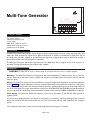
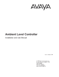
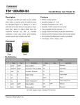
Multi-Tone Generator
Installation and Use Manual
Issue 1, October 1999
© 1999 Bogen Communications, Inc.
All rights reserved. 54-2020-01 9910
Model: LUMUTGEN
PEC Code: 5335-500
COM Code: 408184240
Select Code: 701-000-104
© 1999 Bogen Communications, Inc.
All Rights Reserved. Printed in U.S.A.
Notice
Every effort was made to ensure that the information in
this guide was complete and accurate at the time of printing. However, information is subject to change.
Important Safety Information
Always follow these basic safety precautions when installing
and using the unit.
1. Read and understand all instructions.
2. Follow all warnings and instructions marked on the product.
3. DO NOT block or cover the ventilation slots and openings.They prevent the product from overheating. DO NOT
place the product in a separate enclosure or cabinet, unless
proper ventilation is provided.
4. Never spill liquid on the product or drop objects into the
ventilation slots and openings. Doing so may result in serious damage to the components.
5. Repair or service must be performed by a factory
authorized repair facility.
6.The product is provided with a UL-CSA approved, 3-wire
ground type plug.This is a safety feature. DO NOT defeat
the safety purpose of the grounding type plug. DO NOT
staple or otherwise attach the AC power supply cord to
building surfaces.
7. DO NOT use the product near water or in a wet or
damp place (such as a wet basement).
8. DO NOT use extension cords.The product must be
installed within 6 feet of a grounded outlet receptacle.
9. DO NOT install telephone wiring during a lightning
storm.
10. DO NOT install telephone jacks in a wet location
unless the jack is specifically designed for wet locations.
11. Never touch uninsulated wires or terminals, unless the
line has been disconnected at the paging or controller
interface.
12. Use caution when installing or modifying paging or control lines.
Support Information
Paging systems integrated with small phone systems such as
Merlin Legend and Partner are supported by the National
Service Assistance Center (NSAC).The main number for
the NSAC is 800-628-2888. Paging systems integrated with
large switches such as the DEFINITY G3 are supported by
the Technical Service Center (TSC).The main number for
the TSC is 800-242-2121.
Page 2 of 4
Multi-Tone Generator
REM STATUS
+ 12-48
VDC
-
AUDIO IN
COM
-TRIGGER
-RESET
-STEADY TONE
-PULSED TONE
-SLO WHOOP
-CHIME
-CONTINUOUS
TONE LEVEL
PITCH
TBA
SIG OUT
Package Contents
Your carton contains:
* Multi-Tone Generator Unit
* Power Supply
* Male RCA to Wires Connector
* Female RCA to Wires Connector
* Installation and Use Manual
Description
The Multi-Tone Generator is capable of generating four distinct signals: pulsed tone, slow whoop, repeating chime, and
steady tone. Each of these four signals may be applied continuously or limited to a double burst (single burst only of
the steady tone) for alarm signalling or pre-announcement. Signals are triggered by an external device that provides a
contact closure. Both tone level and pitch are adjustable.
The Multi-Tone Generator will accept a high-level (max. 1.5V RMS) input from a program source, such as a tuner or
tape deck.Tone signal precedence over program input is built-in.
Installation
CAUTION: To reduce the risk of fire or electric shock, do not expose this unit to rain or excessive moisture.
Mounting - The Multi-Tone Generator is designed for wall mount applications. To wall mount this unit, use the four
5/8” pan head screws with nylon washers (screws and washers not provided). Place the unit flush with the wall and
screw it in place.
Wiring - The Multi-Tone Generator can be installed in a variety of configurations, dependent upon specific application
criteria. Figure 1 (on page 4) illustrates a common method of generating a tone signal over program (i.e., tape player,
tuner) input.When the contacts of an external switching device are closed, program input is interrupted by a burst of
one of the tone signals. For longer signal duration, connect the CONTINUOUS and TRIGGER terminals (dotted line).
The tone signal will be continuously generated until the external switch contacts (ALARM CLOSURE) are reopened.
Power Supply - The Multi-Tone Generator requires a power source of between 12 and 48V DC, either positive or
negative ground.
1. Connect the grounding lead from the chassis to the positive (+) terminal if a positive grounding system is used. Be
certain that the Multi-Tone Generator chassis does not come into contact with any other equipment with a negative
ground.
2. If a negative-ground system is used, connect the grounding lead to the negative (-) terminal.
Page 3 of 4
CONT
+
12-48
VDC
-
SLO WHOOP
REM STATUS
AMPLIFIER
PULSED TONE
TUNER
AUDIO IN
STEADY TONE
COM
CONNECT ONE
AS REQUIRED
TO POWER SUPPLY
CHIME
FOR LONGER SIGNAL DURATION,
CONNECT CONTINUOUS AND TRIGGER
TERMINALS (DOTTED LINE).
SIGNAL WILL GENERATE TILL
EXTERNAL CONTACTS REOPEN.
RESET
SIG OUT
AUX
TRIGGER
TBA
TO CONTACT
CLOSURE
C 74-6220-01
Figure 1 - Tone Signalling Over a Program Source
CONT
12-48
VDC
TO POWER SUPPLY
-
CHIME
SLO WHOOP
REM STATUS
AMPLIFIER
TUNER
PULSED TONE
AUDIO IN
STEADY TONE
CONNECT
AS REQUIRED
+
COM
RESET
STOP
SIG OUT
AUX
TRIGGER
START
TBA
C 74-2723-01
Figure 2 - Generating a Continuous Emergency Alarm
Figure 2 shows how the Multi-Tone Generator may be used for emergency alarm signalling in an unattended system.
Program input is interrupted by a continuous alarm tone when an external sensing and switching device (i.e., a bi-metal
sensor) momentarily closes the contact at the TRIGGER terminal (“START”).A second external momentary switch connected to the RESET terminal (“STOP”) restores the circuit when the switch is momentarily closed.
Operation
Tone Level - Tone level can be regulated by the front-panel screwdriver-adjustable TONE LEVEL control. Clockwise
rotation increases the level of the tone signal.
Pitch Control - A recessed, screwdriver-adjustable, PITCH control is located on the side-panel and is used to
adjust the frequency of the tone signal.The signal can be varied to suit the individual application requirement.
Page 4 of 4