1
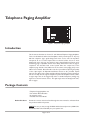
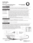
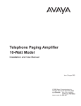
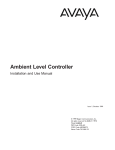
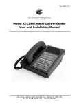
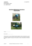
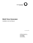
Telephone Paging Amplifier
35- and 100-Watt Models
Installation and Use Manual
Issue 1, October 1999
© 1999 Bogen Communications, Inc.
All rights reserved. 54-2019-01 9910
LU35WAMP: PEC Code: 5328-035
COM Code: 408186070
LU100WAMP: PEC Code: 5328-101
COM Code: 408186088
Select Code: 701-000-100
© 1999 Bogen Communications, Inc.
All Rights Reserved. Printed in Korea.
Notice
Every effort was made to ensure that the information in this
guide was complete and accurate at the time of printing.
However, information is subject to change.
Important Safety Information
Always follow these basic safety precautions when installing and
using the unit:
1. Read and understand all instructions.
2. Follow all warnings and instructions marked on the product.
3. DO NOT block or cover the ventilation slots and openings.
They prevent the product from overheating. DO NOT place
the product in a separate enclosure or cabinet, unless proper
ventilation is provided.
4. Never spill liquid on the product or drop objects into the
ventilation slots and openings. Doing so may result in serious
damage to the components.
5. Repair or service must be performed by a factory authorized
repair facility.
6. The product is provided with a UL-CSA approved, 3-wire
ground type plug. This is a safety feature. DO NOT defeat the
safety purpose of the grounding type plug. DO NOT staple or
otherwise attach the AC power supply cord to building
surfaces.
7. DO NOT use the product near water or in a wet or damp
place (such as a wet basement).
8. DO NOT use extension cords.The product must be installed
within 6 feet of a grounded outlet receptacle.
9. DO NOT install telephone wiring during a lightning storm.
10. DO NOT install telephone jacks in a wet location unless the
jack is specifically designed for wet locations.
11. Never touch uninsulated wires or terminals, unless the line
has been disconnected at the paging or controller interface.
12. Use caution when installing or modifying paging or control
lines.
Support Information
Paging systems integrated with small phone systems such as
Merlin Legend and Partner are supported by the National
Service Assistance Center (NSAC). The main number for the
NSAC is 800-628-2888. Paging systems integrated with large
switches such as the DEFINITY G3 are supported by the
Technical Service Center (TSC). The main number for the TSC
is 800-242-2121.
Trademarks
Aphex Aural Exciter is a registered trademark of Aphex
Systems, Ltd.
Domestic and International Approvals
UL Listed E15903.
Page 2 of 12
Contents
Page
INTRODUCTION ..........................................................................................................................4
PACKAGE CONTENTS..............................................................................................................4
INSTALLATION..............................................................................................................................5
Mounting ............................................................................................................................5
Wall Mounting ....................................................................................................................................5
Rack Mounting ..................................................................................................................................5
WIRING CONNECTIONS ........................................................................................................6
Input Wiring......................................................................................................................6
TEL Input and Control Pair ............................................................................................................6
Music Input..........................................................................................................................................7
Microphone Input ..............................................................................................................................7
Night Ringer Connections ................................................................................................................8
Bridging Inputs....................................................................................................................................8
Input Cover Replacement ................................................................................................................8
‘
Output Wiring ................................................................................................................9
Speaker Connections ........................................................................................................................9
LUWMT1A Connector ..................................................................................................................10
Output Cover Replacement..........................................................................................................10
OPERATION ..................................................................................................................................11
Indicators ..................................................................................................................11-12
Page 3 of 12
Telephone Paging Amplifier
POWER
PEAK LEVEL
APHEX
TREBLE
BASS
RINGER VOLUME
MUSIC MUTE
MUSIC VOLUME
MIC VOLUME
AMPLIFIER
TEL VOLUME
ALC
BRIDGING
MUSIC IN
TEL
CONTROLS
COM
MIC
MIC
BAL
GND
+
TEL
BAL
T
R
CONTACT
RING
TEL
RING
Figure 1: Telephone Paging Amplifier
Introduction
This document describes the Lucent 35- and 100-watt Telephone Paging Amplifiers.
These are full-featured, wall-mounted amplifiers which provide inputs for dry loop
600-ohm telephone page signal, background music source, and low impedance
microphone. A set of control inputs allow an external contact closure to mute
background music and open the telephone page channel. Background music mute
level during page is adjustable and the music slowly fades back in after the page is
completed. An automatic level control system limits the output level of the
telephone page channel so that differences in the volume of the paging party's voice
will be less noticeable. Bass and treble controls are provided for adjusting the quality
of the output signal. An Aphex® Aural Exciter feature is also provided. Aphex
improves the clarity of the output signal by replacing the higher frequency harmonics
that are normally lost through the telephone system.This amplifier includes a builtin night ringer that can be triggered by either a standard telephone (analog) ring
signal or an external contact closure. The night ringer mutes the background music,
but not pages.
Package Contents
* Telephone Paging Amplifier unit
* Pair of Rack Mount Brackets
* 8 mounting screws
* Installation and Use Manual
Before You Start
Review the contents of the box. Read through this entire manual to understand how
this product installs and operates.
NOTE: Be sure you have enough 22 AWG shielded, twisted pair wire (COM Code:
401882956, PEC Code: 2734-SPK) for your speaker runs.
Page 4 of 12
Figure 2: Mounting the Amplifier
SCREW 1/2"
TRUSS-HEAD
PO
WE
R
L
LE
AK
VE
PE
X
AP
TR
HE
EB
BA
LE
SS
ER
RING
S
MU
IC
ME
LU
VO
MU
ME
LU
VO
SIC
MU
MIC
TE
VO
LV
LU
OLU
....
....
....
....
.
....
....
TE
....
....
....
....
....
ME
ME
ALC
RACK
MOUNTING
SCREWS ARE
NOT SUPPLIED
Installation
Mounting
The amplifier is designed for wall mount applications but can also be mounted in a
standard 19" rack using the included rack adapter brackets. The 35W amplifier
weighs 16 lbs. and the 100W amplifier weighs 21 lbs.
NOTE: The amplifier will produce heat during operation which will rise and may
cause problems for temperature-sensitive equipment mounted above it. Mount the
amplifier near the top of the backboard (for wall mounting) or rack (for rack
mounting) so that no other equipment will be above it. If this is not possible, then
allow at least 12" between the top of the amplifier and the bottom of any
equipment positioned above it. Also allow at least 4" between the bottom of the
amplifier and any equipment below it to allow for adequate air circulation.
Wall Mounting
To wall mount this unit, use the four 5/8” pan head screws with nylon washers
provided (see Figure 2).The screws should protrude approximately ¼" from the
surface of the backboard. Lift the amplifier and place it over the 4 screws using the
keyhole slots in the flanges at the sides of the amplifier.The screws should engage
the keyhole slots. Once in the keyhole slots, tighten the screws to secure the
amplifier.
Rack Mounting
To mount the amplifier in a 19" rack, it is first necessary to attach the rack adapter
brackets to the amplifier flanges (see Figure 2). Start the four ½" truss-head selftapping screws into the 2 small round holes in each of the adapter brackets. Be
certain to secure the screws from the correct side of the brackets.The brackets
should mirror each other so that they can be installed on opposite sides of the
amplifier. From behind the amplifier, slip the rack adapter, with screws, through the
opening in the keyhole slots and slide them up in to the keyhole slots.Tighten the
screws securely. Lift the amplifier up to the front of the rack and secure it to the
rack with the necessary screws (not included). The amplifier will protrude out
from the front of the rack.
Page 5 of 12
Wiring Connections
IMPORTANT: Before making any connections or wiring changes to the amplifier
or any equipment connected to the amplifier, make sure that the amplifier is NOT
plugged into an AC outlet.
NOTE: The amplifier does not have a power switch, so it must be unplugged in
order to turn the power off.
Input Wiring
All signal input and control wiring is made to the terminal strip and RCA connectors
beneath the left side access cover. Loosen the 2 Phillips-head screws on each side
of the cover and remove it.
TEL Input and Control Pair
The telephone input is a 600-ohm, dry loop, balanced input. It is controlled by a dry
contact closure that is made between the control terminals labeled TEL and COM.
Shorting these terminals together will mute the background music input and open
the Tel page channel (see Figure 3).
NOTE: In instances where the amplifier is to be placed permanently in the Tel page
mode, a wire jumper must be installed between the TEL and COM terminals.
Telephone Paging Amplifier
Figure 3: Wiring for TEL Input
MIC VOLUME
TEL VOLUME
ALC
TEL
CONTROLS
COM
MIC
Universal Paging Access Module
BGM
IN
MODE
OFF
24VDC PWR SUPPLY
48VDC PWR SUPPLY
CONFIRMATION TONE
PREANNOUNCE TONE
VOX DISABLE
VOX ENABLE
S1,S2
S3
S4
S5
ON
S1,S2
PHONE SYSTEM
S4
S3
EXT VOX ENABLE
PAGING OUTPUT
S5
CONTACT CLOSURE A
PAGE PORT
INPUT
POWER SUPPLY
(TRUNK ACCESS ONLY)
T
R
+M
-M
PT
PR
N.O.
COM
+24/48
-24/48
(0.1A)
MIN
MAX
TONE VOL.
MIN
MAX
VOX DELAY
MIN
MAX
PAGING TIME
MODE
SWITCHES
BGM
VOL
CONTACT CLOSURE B
N.O.
COM
Page 6 of 12
BRIDGING
MUSIC IN
APHEX
MIC
BAL
+
GND
TEL
BAL
T
R
CONTACT
RING
TEL
RING
T
R
Tel Input to Universal Coupler
After properly connecting your Universal Coupler (909) to your Auxiliary Trunk
port, set your switches as follows: C1/C2 to C2; Rocker Switch 3 closed; and all
others open. Coming out of the J2 Jack of the Coupler, connect the blue/white pair
to the amplifier Tip and Ring. Connect the brown/white pair to Tel and Com on the
control terminals.
Music Input
A single RCA connector is provided for the connection of a background music
source. Use a male RCA-to-RCA cable (not included) to make this connection. This
is a mono input and requires that the output of stereo sources be converted to
mono by using a Y-adapter (not included). Use a LUWMT1A to balance the music
input, if necessary, to reduce hum/noise from a grounded music source.
Microphone Input
A high gain, low impedance microphone input is provided in this amplifier. It is
designed to work with microphone LUSZMIC (Com Code: 408186238, PEC Code:
5335-400). Connect the microphone's black wire to the amplifier's "-" (negative)
terminal under the MIC BAL connections. Connect the microphone’s Red wire to
the "+" (positive) terminal. Connect the shield wire from the microphone to the
adjacent GND terminal. Connect the microphone's white lead to the Control
terminal marked MIC and the green lead to the COM. (See Figure 4.)
Two conductor shielded microphone wire should be used to extend the cable from
the microphone. 22 AWG shielded, twisted pair speaker cable (Com Code:
401882956, PEC Code: 2734-SPK) will also work. When extending microphone
cable, be sure to connect the shields of the microphone cable to the extension wire.
Figure 4: Connect Microphone to Telephone Paging Amplifier
MIC VOLUME
TEL VOLUME
ALC
MUSIC IN
APHEX
TEL
CONTROLS
COM
MIC
MIC
BAL
+
GND
BRIDGING
TEL
BAL
T
R
CONTACT
RING
T
TEL
RING
R
K
C
LO
Shield - GND
White - MIC ‘CONTROLS’
Green - COM ‘CONTROLS’
Microphone
Cable
Red - MIC + ‘MIC BAL’
Black - MIC - ‘MIC BAL’
Page 7 of 12
Night Ringer Connection
Either a standard telephone (analog) ring signal (90 - 105 V AC, 20 - 30 Hz) or an
external contact closure activates the night ringer function of the amplifier. To
activate the night ringer using standard telephone (analog) ring, connect the analog
station's tip lead to the TEL RING "T" terminal and connect the ring lead to the "R"
terminal. If using an external contact closure, connect the closure pair across the
CONTACT RING terminals (not polarized).The night ringer follows the cadence of
the activating signal.
Bridging Inputs
Bridging increases the total output power of the system. For example, when two
100-watt amplifiers are bridged, the total output capacity is 200 watts. Bridging is
also a means by which to increase the number of amplifier inputs to an amplifier by
using the input stage of a second amplifier (see Figure 5).The inputs of two or more
amplifiers can be combined by using the bridging connections provided on these
amplifiers.An RCA-to-RCA cable (not included) is used to connect the bridging jacks
of different amplifiers together. Once bridged, each amplifier will amplify the inputs
present on both amplifiers.The level control of a particular input on an amplifier will
control the volume of this signal on both amplifiers. The cable used to bridge
amplifiers should not exceed 20 feet in length.
NOTE: You can only bridge up to 3 amplifiers at one time.
Input Cover Replacement
When all connections are made, remove an appropriate knockout on the input
cover. Replace the cover and tighten the screws while dressing the wires through
the knockout hole.
MIC VOLUME
TEL VOLUME
POWER
ALC
PEAK LEVEL
APHEX
TREBLE
BRIDGING
MUSIC IN
APHEX
BASS
RINGER VOLUME
TEL
MIC
BAL
CONTROLS
COM
MIC
TEL
BAL
GND
T
+
CONTACT
RING
R
T
TEL
RING
MUSIC MUTE
R
MUSIC VOLUME
MIC VOLUME
AMPLIFIER
TEL VOLUME
ALC
BRIDGING
MUSIC IN
TEL
CONTROLS
COM
MIC
MIC
BAL
GND
+
TEL
BAL
T
CONTACT
RING
R
TEL
RING
POWER
MIC VOLUME
PEAK LEVEL
APHEX
TREBLE
TEL VOLUME
BASS
ALC
RINGER VOLUME
MUSIC MUTE
MUSIC VOLUME
BRIDGING
MUSIC IN
APHEX
MIC VOLUME
AMPLIFIER
TEL VOLUME
ALC
TEL
CONTROLS
COM
MIC
MIC
BAL
+
GND
TEL
BAL
T
R
CONTACT
RING
TEL
RING
T
BRIDGING
MUSIC IN
R
TEL
CONTROLS
COM
MIC
MIC
BAL
+
GND
TEL
BAL
T
R
CONTACT
RING
TEL
RING
Figure 5: Bridging Inputs
Page 8 of 12
Output Wiring
All output wiring connections are made to the terminal strip located under the right
side access panel. Loosen the 2 Phillips-head screws on each side of the cover and
remove the cover.
IMPORTANT: Before making any connections or wiring changes to the amplifier
or any equipment connected to the amplifier, make sure that the amplifier is NOT
plugged into an AC outlet.
NOTE: The amplifier does not have a power switch, so it must be unplugged in
order to turn the power off.
Speaker Connection
70-volt speaker connections are made between the 70V and COM terminals on the
output terminal strip (see Figure 6). Use a 22 AWG shielded, twisted pair cable (Com
Code: 401882956, Pec Code: 2734-SPK). Connect the shield of the cable to the
GND terminal of the output terminal strip. The COM and GND Terminals of the
output terminal strip are connected using a shorting clip. The shorting clip enables
the amplifier output to act as an unbalanced output (one side of the output
connected to ground). If desired, the output can be made to be a balanced output
with no connection to ground. To balance the output, simply remove the shorting
clip. All speaker connections remain the same as above including connecting the
shield to the GND terminal.
NOTE: The amplifier output terminal strip also includes terminals for 16-ohm, 25V
and 25VCT speaker connections. These are provided for special applications and are
generally not used.
CLASS 2 WIRING ACCEPTABLE
16
25V 25VCT COM GND
_
70V
+
RINGER VOLUME
MUSIC MUTE
MUSIC VOLUME
MIC VOLUME
AMPLIFIER
TEL VOLUME
ALC
BRIDGING
MUSIC IN
CONTROLS
COM
MIC
MIC
BAL
+
GND
TEL
BAL
T
R
CONTACT
RING
TEL
RING
_
TEL
+
Figure 6: Speaker Connection, Output Wiring
Page 9 of 12
Figure 7 : LUWMT1A Connection to RCA Jack on Amplifier
RCA Jack
.
....
ABLE .....
EPT
CC
G A .....
IRIN
2 W ...
SS
..
CLA
.
....
T-..A
WM
.
....
LUWMT1A
Amplifier
LUWMT1A Connector
An RCA jack is provided near the output terminal strip for connection to an
LUWMT1A impedance matching transformer (Com Code 405891680). A 600-ohm,
telephone level output signal can be obtained by plugging the RCA connector of the
LUWMT1A into this jack and taking the output signal off of the LUWMT1A screw
terminals. (See Figure 7.)
NOTE: For information on connecting Telephone Paging Amplifiers to the Lucent
PCM Paging System Zone Controller (model LUPCM), please refer to the LUPCM
instruction manual.
Output Cover Replacement
When all output connections are made, remove the appropriate knockout on the
input cover. Replace the cover and tighten the screws while dressing the wires
through the knockout hole.
Page 10 of 12
Operation
IMPORTANT: Before plugging the amplifier into an AC outlet, turn all volume
controls to their full counterclockwise positions and all other controls to their
reference position or to mid rotation.
Indicators
POWER IND
The POWER IND LED illuminates whenever AC power is applied to the amplifier
(there is no power switch on the amplifier).
PEAK LEVEL
The PEAK LEVEL LED illuminates whenever the speaker output signal level
approaches its maximum level. This indicator is used when setting volume levels.
Maximum output level is achieved when the PEAK LEVEL indicator flashes
intermittently on loud peaks of the input signal. If the indicator illuminates steadily,
the output signal volume is set too high and distortion is occurring. Decrease the
volume control for the appropriate input until the indicator flashes only
occassionally.
TEL VOLUME
This control adjusts the level of the telephone page output. A reference level setting
position is provided with this control. When set to this position, the output level of
the page should be about maximum. Further adjustment can be made using the
PEAK LEVEL indicator described above.
ALC
The ALC controls the level at which the amplifier will begin to limit the output signal
level. A reference setting position is provided for this control. Normally, the
reference position provides optimum performance; however, if further adjustment is
desired, use the following steps for setting the ALC control.
Manual Output Adjustment Procedure (follow only if minor adjustments to the
reference settings are not adequate)
1) Disable ALC by turning ALC control.
2) Make a page, speaking softly, yet distinctly. Set the TEL VOLUME control to the
desired paging level during this page.
3) Make another page speaking relatively loudly this time. Rotate the ALC control,
while making the page, until it has the same loudness as the first page.
NOTE: The TEL Volume and ALC controls work together to set the output level.
When both controls are set to the reference positions, the amplifier provides a
nominal 70V signal output (optimum).
NOTE: The PEAK LEVEL indicator should not show excessive peaking during loud
pages. If this is occurring, the ALC control must be further increased.
Page 11 of 12
MUSIC VOLUME
This control adjusts the level of the background music output. No reference level
setting position is provided. The background music level should be set to an
acceptable level without overdriving the system. When adjusting this level, the PEAK
LEVEL indicator should be observed to ensure that the amplifier signal is not
distorted.
MUSIC MUTE
This control adjusts the level of the background music heard during a paging
announcement. No reference level setting position is provided. The background
music mute level should be set to the customer's satisfaction, but the page
announcement must always be easily heard above the background music.
MIC VOLUME
This control adjusts the level of the microphone page output. A reference level
setting position is provided with this control. When set to this position, the output
level of the page should be about maximum. Further adjustment can be made by
observing the PEAK LEVEL indicator.
CAUTION: Microphone should not be placed near any paging loudspeakers.
RINGER VOLUME
This control adjusts the level of the night ringer tone output. No reference level
setting position is provided. The background music level should be set to the
customer's satisfaction. When adjusting this level, the PEAK LEVEL indicator should
be used to ensure that the amplifier signal is not distorted.
APHEX
This control adjusts the amount of Aphex® Aural Exciter effect mixed in to the page
signal. No reference position is provided for this feature. To use this function, the
APHEX switch beneath the input connection cover must be set to ON. Setting this
switch to OFF bypasses the Aphex effect and makes the control inoperable.With the
APHEX switch turned on, make a page and rotate the control until the audio sounds
crisp and clear.
BASS and TREBLE
Bass and treble controls are provided to adjust the high frequency and low frequency
response of the paging system. Reference positions are provided for these controls.
When set to these positions, the frequency response of the system will be flat. Set
the controls to the customer’s satisfaction. Clockwise rotation increases (boosts)
the response and counterclockwise reduces (cuts) the response. Increasing bass
and/or treble can cause output signal peaks to increase. Check the PEAK LEVEL
indicator after making bass adjustment and lower the music input volume if excess
peaking occurs.
Page 12 of 12