1
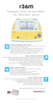
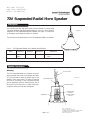
PEC Code: 5331-210
COM Code: 408184141
Model: LU30WR70VH
70V Suspended Radial Horn Speaker
Description
Horn speakers produce high sound levels, and are capable of covering large
noisy areas. Minimum effective mounting height for a horn is 15 feet, 20 feet is
preferable.The 70V Suspended Radial Horn Speaker (see Figure 1) is used when
its 360-degree sound dispersion pattern is required.
Figure 1
The chart below lists specifications for the 70V Suspended Radial Horn Speaker.
Chart 1. 70V Suspended Radial Horn Speaker Specifications
Power
30 watts
Frequency
300 Hz
14 kHz
Dispersion
Sound Level *
360˚
113 dBspl
Dimensions
13" W x 11-3/4" H
6.0 lbs.
*Measured 1 meter from speaker at rated po wer.
Speaker Installation
Mounting
10-FOOT CHAIN
The 70V Suspended Radial Horn Speaker has a post
and ring located on the base of the speaker (see Figure
2). The ring is used to attach the speaker post to the
supplied 10-foot metal chain. The means of attaching
the chain to the ceiling or other overhead structure
must be sufficiently secure to withstand a pull test of
30 pounds; if local construction or safety codes specify a greater value, then that value shall govern.
Figure 2
ATTACHMENT RING
SPEAKER CABLE
TERMINALS
Page 1 of 2
VOLUME LEVEL
CONTROL
(DO NOT FORCE
PAST #7)
Issue 1, October 1999
54-2013-01 Printed in USA 9910
© 1999 Bogen Communications Inc. All rights reserved.
Specifications subject to change without notice.
Select Code: 701-000-122
Wire Connections
The speaker has screw-type terminals, which are protected by a clear plastic cover. The cover also acts as a strain
relief for the wires after they are connected. The procedure for connecting the speaker is given in the following
steps:
1. Remove the plastic cover from the terminal area by removing
the two screws. Replace the screws so they will not be misplaced.
Note: Use 22 AWG shielded, twisted
pair on all wire runs. COM Code:
401882956. PEC Code: 2734-SPK.
2. Make the connections and dress the wire as shown in Figure 2.
3. When using shielded speaker wire and wiring from speaker to speaker, wire the shield drains to provide a continuous shield to the next speaker. Otherwise, clip the shield wire at the point it emerges from the main cable.The
shield wire should never be terminated on the speaker.
4. Do not replace the plastic cover until final power adjustments have been made.
Note: When connecting from speaker to speaker, the speaker must be kept in phase. This means that all
number 1 (-) terminals must connect on the same wire, and all number 2 (+) terminals must be connected on
the other wire.
Final Power Adjustments
1. Ensure that the speaker is set to its lowest setting
(this will prevent an excessively loud page when first used).
2. While a page is in process, adjust the volume control with a
screwdriver. Turn clockwise to increase the volume
(see Chart 2).
Chart 2. Impedance and Power Output
Switch Setting
Ohms
70V, Watts
1
2500
1.8
2
1300
3.7
3
666
7.5
4
333
15
5
167
30
6
89
Do Not Use
7
45
Do Not Use
3. Install the plastic cover.
Page 2 of 2