1
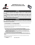
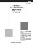
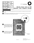
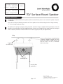
PEC Code: 5330-235
COM Code: 408184075
Model: LUSQIN70VS
Indoor
PEC Code: 5330-240
COM Code: 408184083
Model: LUSQOT70VS
Outdoor
70V Surface-Mount Speaker
Speaker Installation
1
The first step is to determine where the speaker(s) will be mounted. Ensure power is not connected to speaker wires prior
to installation.
Follow all local safety and building codes and route 70-volt speaker wires to desired ceiling location. Pull approximately
12” of wire through opening in ceiling.
2
Pull speaker wire through top (large) opening of speaker enclosure. Using the supplied mounting hardware, secure the
enclosure to the ceiling. Note that two toggle bolt/screws (for sheet rock ceilings) and two wood screws (for securing to
solid wood/beams) have been included. Utilize the two washers (supplied) as well (see diagram below).
Ceiling
Use two of the enclosure mounting holes as
a template (diagonally opposed), and mark
screw hole locations. If toggle bolts will be
used, use a drill to cut two, 1/2” diameter
holes in the ceiling.
Toggle bolts
(for sheet rock)
Enclosure
Mounting Holes
Mounting Bolts
and Washers
Page 1 of 2
Issue 1, October 1999
54-2017-01 Printed in USA 9910
© 1999 Bogen Communications Inc. All rights reserved.
Specifications subject to change without notice.
3
The next step is to attach the speaker wires to the
appropriate taps (wires) located on the back of the
speaker. The speaker will also work perfectly well
with these connections reversed. However, it is
important to be consistent in the wiring of the
speakers in the system. If adjacent speakers have
reversed wiring connections, they will tend to cancel each other’s bass response, diminishing the
sound quality.
Use crimp-type
connectors
(included)
Note: With 70V speakers select the lowest tap setting (1/4W) before testing the speakers. This ensures
that nobody will be "blasted" when a page is made for
the first time.
Based on specific area dB levels, select the desired
power tap settings:
Green = 1/4W
Yellow = 1/2W
Orange = 1W
Red = 2W
Brown = 4W
Connect the power tap wire (use supplied crimptype connector) to the (+) side of the paging
system.
Install the (-) side of the paging system (use supplied crimp-type connector) to the black common
lead.
Individually tape or clip each tip of exposed wire
on the unused power taps and place them neatly
around the speaker housing. This will ensure that
there will not be any shorts/grounds or wattage
problems in the speaker enclosure or wire run.
Note: Use 22 AWG shielded, twisted pair on all
wire runs. Com Code: 401882956. Pec Code:
2734-SPK. Connect speaker wire shield to the
ground (GND) terminal of the amplifier’s output.
Carry the ground through all speaker cables by
tying the shields of the speaker cables together in
a “daisy chain” fashion. Do not connect the
shield to the speaker itself. The shield is only
connected at the amplifier end and simply floats.
4
Enclosure
Secure the speaker/face plate assembly to the
mounted enclosure. Use four 1" screws (included).
Speaker/Face
Plate Assembly
Page 2 of 2