1
BCM Rls 6.0
BCM Monitor
Task Based Guide
BCM Monitor
Copyright © 2010 Avaya Inc.
All Rights Reserved.
Notices
While reasonable efforts have been made to ensure that the information in this document is complete and accurate
at the time of printing, Avaya assumes no liability for any errors. Avaya reserves the right to make changes and
corrections to the information in this document without the obligation to notify any person or organization of such
changes.
Documentation disclaimer
Avaya shall not be responsible for any modifications, additions, or deletions to the original published version of
this documentation unless such modifications, additions, or deletions were performed by Avaya. End User agree to
indemnify and hold harmless Avaya, Avaya’s agents, servants and employees against all claims, lawsuits, demands
and judgments arising out of, or in connection with, subsequent modifications, additions or deletions to this
documentation, to the extent made by End User.
Link disclaimer
Avaya is not responsible for the contents or reliability of any linked Web sites referenced within this site or
documentation(s) provided by Avaya. Avaya is not responsible for the accuracy of any information, statement or
content provided on these sites and does not necessarily endorse the products, services, or information described or
offered within them. Avaya does not guarantee that these links will work all the time and has no control over the
availability of the linked pages.
Warranty
Avaya provides a limited warranty on this product. Refer to your sales agreement to establish the terms of the
limited warranty. In addition, Avaya’s standard warranty language, as well as information regarding support for
this product, while under warranty, is available to Avaya customers and other parties through the Avaya Support
Web site: http://www.avaya.com/support
Please note that if you acquired the product from an authorized reseller, the warranty is provided to you by said
reseller and not by Avaya.
Licenses
THE
SOFTWARE
LICENSE
TERMS
AVAILABLE
ON
THE
AVAYA
WEBSITE,
HTTP://SUPPORT.AVAYA.COM/LICENSEINFO/ ARE APPLICABLE TO ANYONE WHO DOWNLOADS,
USES AND/OR INSTALLS AVAYA SOFTWARE, PURCHASED FROM AVAYA INC., ANY AVAYA
AFFILIATE, OR AN AUTHORIZED AVAYA RESELLER (AS APPLICABLE) UNDER A COMMERCIAL
AGREEMENT WITH AVAYA OR AN AUTHORIZED AVAYA RESELLER. UNLESS OTHERWISE
AGREED TO BY AVAYA IN WRITING, AVAYA DOES NOT EXTEND THIS LICENSE IF THE
SOFTWARE WAS OBTAINED FROM ANYONE OTHER THAN AVAYA, AN AVAYA AFFILIATE OR AN
AVAYA AUTHORIZED RESELLER, AND AVAYA RESERVES THE RIGHT TO TAKE LEGAL ACTION
AGAINST YOU AND ANYONE ELSE USING OR SELLING THE SOFTWARE WITHOUT A LICENSE. BY
INSTALLING, DOWNLOADING OR USING THE SOFTWARE, OR AUTHORIZING OTHERS TO DO SO,
YOU, ON BEHALF OF YOURSELF AND THE ENTITY FOR WHOM YOU ARE INSTALLING,
DOWNLOADING OR USING THE SOFTWARE (HEREINAFTER REFERRED TO INTERCHANGEABLY
AS "YOU" AND "END USER"), AGREE TO THESE TERMS AND CONDITIONS AND CREATE A
BINDING CONTRACT BETWEEN YOU AND AVAYA INC. OR THE APPLICABLE AVAYA AFFILIATE
("AVAYA").
Copyright
Except where expressly stated otherwise, no use should be made of the Documentation(s) and Product(s) provided
by Avaya. All content in this documentation(s) and the product(s) provided by Avaya including the selection,
arrangement and design of the content is owned either by Avaya or its licensors and is protected by copyright and
other intellectual property laws including the sui generis rights relating to the protection of databases. You may not
modify, copy, reproduce, republish, upload, post, transmit or distribute in any way any content, in whole or in part,
including any code and software. Unauthorized reproduction, transmission, dissemination, storage, and or use
without the express written consent of Avaya can be a criminal, as well as a civil offense under the applicable law.
Third Party Components
Certain software programs or portions thereof included in the Product may contain software distributed under third
party agreements ("Third Party Components"), which may contain terms that expand or limit rights to use certain
portions of the Product ("Third Party Terms"). Information regarding distributed Linux OS source code (for those
Products that have distributed the Linux OS source code), and identifying the copyright holders of the Third Party
Components and the Third Party Terms that apply to them is available on the Avaya Support Web site:
http://support.avaya.com/Copyright.
Trademarks
The trademarks, logos and service marks ("Marks") displayed in this site, the documentation(s) and product(s)
provided by Avaya are the registered or unregistered Marks of Avaya, its affiliates, or other third parties. Users
are not permitted to use such Marks without prior written consent from Avaya or such third party which may own
the Mark. Nothing contained in this site, the documentation(s) and product(s) should be construed as granting, by
implication, estoppel, or otherwise, any license or right in and to the Marks without the express written permission
of Avaya or the applicable third party. Avaya is a registered trademark of Avaya Inc. All non-Avaya trademarks
are the property of their respective owners.
2
NN40011-030 Issue 1.2 BCM Rls 6.0
BCM Monitor
Downloading documents
For the most current versions of documentation, see the Avaya Support. Web site: http://www.avaya.com/support
Contact Avaya Support
Avaya provides a telephone number for you to use to report problems or to ask questions about your product. The
support telephone number is 1-800-242-2121 in the United States. For additional support telephone numbers, see
the Avaya Web site: http://www.avaya.com/support
Copyright © 2010 ITEL, All Rights Reserved
The copyright in the material belongs to ITEL and no part of the material may
be reproduced in any form without the prior written permission of a duly
authorised representative of ITEL.
NN40011-030 Issue 1.2 BCM Rls 6.0
3
BCM Monitor
Table of Contents
BCM Monitor...................................................................... 5
Overview .......................................................................................... 5
Required Information ....................................................................... 5
Supported Operating Systems ...........................................................................5
Flowchart ......................................................................................... 6
Installing BCM Monitor ..................................................................... 7
Opening BCM Monitor ................................................................... 11
Tab Descriptions ............................................................................ 13
BCM Info Tab ...................................................................................................13
Media Card Tab ...............................................................................................14
Voice Ports Tab ...............................................................................................16
IP Devices Tab.................................................................................................17
RTP Sessions Tab ...........................................................................................19
Universal ISDN Protocol Tab ...........................................................................21
Line Monitor .....................................................................................................23
Usage Indicators Tab .......................................................................................24
Static Snapshots ............................................................................ 26
Dynamic Snapshots ....................................................................... 29
Automatic Snapshot .........................................................................................30
Avaya Documentation Links .......................................... 33
4
NN40011-030 Issue 1.2 BCM Rls 6.0
BCM Monitor
BCM Monitor
Overview
The BCM Monitor allows you to see the current status of various parts of your
system services. You can use this tool during troubleshooting to confirm
current configurations, including CallPilot applications and IP trunk
information.
BCM Monitor is a stand-alone diagnostic tool that allows the user to view
basic information about their BCM system and to monitor certain real time
parameters of the system.
Real time monitoring capabilities include:
Overall system status
IP telephony functions of the BCM system
Utilisation of resources on the Media Card (CSC or BMB)
Operation of telephony applications (e.g. Voice Mail, Contact Centre,
etc.)
Line monitoring; line numbers, digits dialled, originating extensions,
duration etc.
BCM Monitor can be used from a remote PC that has IP connectivity to
the monitored BCM system.
Multiple instances of the BCM Monitor application can be used on a
single PC to monitor several remote BCM systems at the same time.
Required Information
Before commencing installation and usage of BCM Monitor, it would be useful
to obtain the following information:
The Business Communications Manager IP Address, User ID, &
Password.
Supported Operating Systems
This version of BCM Monitor is supported on the following operating systems:
Windows XP Professional SP3
Windows Vista Business, Ultimate, Enterprise
Windows 7 Professional, Ultimate, Enterprise
Citrix
NN40011-030 Issue 1.2 BCM Rls 6.0
5
BCM Monitor
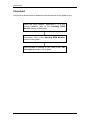
Flowchart
Use the flow chart below to determine which sections of the guide to use.
Install the BCM Monitor application if it is not
already installed: refer to the Installing BCM
Monitor section of this guide
Launch BCM Monitor to view real time BCM
information: refer to the Opening BCM Monitor
section of this guide
View the tabs of interest to you: refer to the Tab
Descriptions section of this guide
6
NN40011-030 Issue 1.2 BCM Rls 6.0
BCM Monitor
Installing BCM Monitor
Note: BCM Monitor may have been installed on your PC if you have installed
Element Manager. If BCM Monitor is installed on your PC, omit this section.
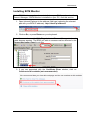
1. Open Internet Explorer.In the address field type (replacing the relevant
part with your BCM IP address): http://<bcm ip address>/
2. Click on Go, or press Return on your keyboard.
Note: You can also use the Web Page button in Element Manager to launch
a web broswer session. The BCM you wish to access must be selected in the
Element Navigation Panel to do this.
3. If you are presented with the Certificate Error window, click on
Continue to this website (not recommended).
NN40011-030 Issue 1.2 BCM Rls 6.0
7
BCM Monitor
4. Accept any further security messages that you may get presented with.
5. You will now see the login screen, enter your BCM User name and
Password. By default these are set to User ID: nnadmin Password:
PlsChgMe! Click on OK.
6. In the Welcome to BCM window, ensure the Main tab has been
selected, and the BCM button clicked.
8
NN40011-030 Issue 1.2 BCM Rls 6.0
BCM Monitor
7. Select BCM Monitor, and click on Run.
8. Accept the licence agreement and click Next.
NN40011-030 Issue 1.2 BCM Rls 6.0
9
BCM Monitor
9. BCM Monitor will be installed and launched, and will try to connect to
the BCM from which it was installed. Click the OK button in the error
window.
10. Close BCM Monitor and follow the procedure to launch the application
in the Opening BCM Monitor section of this guide.
10
NN40011-030 Issue 1.2 BCM Rls 6.0
BCM Monitor
Opening BCM Monitor
To launch BCM Monitor:
1. Select Start, Programs,
Manager, BCM Monitor.
Avaya,
Business
Communications
2. Alternatively BCM Monitor can be selected from your PC‟s Desktop by
double clicking the shortcut icon.
3. BCM Monitor can also be launched from within Element Manager. In
the Administration tab, open the Utilities folder and select BCM
Monitor. Click on the Launch BCM Monitor button.
NN40011-030 Issue 1.2 BCM Rls 6.0
11
BCM Monitor
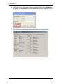
4. The Enter Logon Information window appears. Enter the IP Address of
the BCM, the User Name in the Connect As field, and Password. Click
the Connect button.
5. You will then be presented with the BCM Monitor‟s main screen.
12
NN40011-030 Issue 1.2 BCM Rls 6.0
BCM Monitor
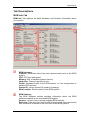
Tab Descriptions
BCM Info Tab
BCM Info Tab displays the basic hardware and firmware information about
your system.
BCM Hardware:
Platform: Information about the main system board used in the BCM
system.
CPU: CPU type and speed.
Memory: Size of installed system memory.
Hard drive: Primary hard drive‟s size.
Profile: Hardware profile of the BCM system (i.e. the configuration of
installed PCI devices).
System ID: Unique system ID (used for licensing).
Serial number: Serial number of the BCM system.
BCM Software:
The BCM Software section contains information about the BCM
software installed on the monitored BCM system.
Version: Version of the currently installed BCM software.
Boot time: Date and time when the BCM system has been last booted
(the information is based on the local time of the BCM system).
NN40011-030 Issue 1.2 BCM Rls 6.0
13
BCM Monitor
Configuration:
The IP Configuration section contains basic information about IP
parameters of the monitored BCM system.
Published IP address: IP address which is used by BCM‟s Voice over
IP software components for external communications over LAN and/or
WAN. Other IP devices on the network (e.g. IP sets) use this address
to communicate with the BCM system.
Next hop: Next hop router. Typically, this is the first router on the
primary network connection.
Installed Devices:
The Installed Devices section contains additional information about
hardware devices installed in the monitored BCM system.
Note: When troubleshooting IP connectivity problems, you should examine
the Published IP Address (an incorrect address may prevent communication
with external devices), the Next Hop Router (an incorrect setting may cause
routing of IP packets to a wrong network adapter) and also IP addresses and
subnet masks of installed network interface cards.
Media Card Tab
The Media Card tab provides information about the media card installed in
the monitored BCM system.
14
NN40011-030 Issue 1.2 BCM Rls 6.0
BCM Monitor
Media Card Hardware:
The Media Card Hardware section contains the following.
Type: Type of the installed card.
Revision: Revision of the card.
Voice Bus channels: Number of media card voice bus channels (an
internal bus that handles communication between the card and
Processor Expansion Cards).
Media Card Firmware:
The Media Card Firmware section contains information about the
firmware installed on the card. This firmware is responsible for all call
processing on the BCM system.
Core load: Identification of the firmware load installed on the Media
Card followed by its version and variant.
Market profile: Market profile (region) used for the initialisation of the
BCM system.
Media Card Configuration:
The Media Card Configuration section contains information about
configurable parameters of the MSC.
DS30 configuration: For older model BCM‟s only (1000/200/400).
Information on the DS30 channel configuration (6/2 or 5/3 split), and for
Partial Double Density mode.
Dial-up WAN Information: For older model BCM‟s only
(1000/200/400). If the Dial-up WAN is enabled or not. When dial-up
WAN is enabled, resources available for other application are
considerably reduced.
Media channels: Number of 64 kbps channels that can be used for
transport of media (typically voice). Media channels are also known as
B channels.
Signalling channels: Number of signalling channels that can be used
by various devices (e.g., IP sets, voice ports). Signalling channels are
also known as D channels.
Processor Expansion Cards: For older model BCM‟s only
(1000/200/400). Number of installed Processor Expansion Cards.
DSP resource units: Total number of logical resource units provided
by all installed Processor Expansion Cards.
DSP Resources:
The DSP Resources section contains detailed information about
firmware tasks loaded on the Master DSP and Processor Expansion
Cards.
Note: When troubleshooting voice path problems on IP devices, you should
examine the percentage of used DSP resources in the DSP Resource control
(see the percentage beside Processor Expansion Cards). If the DSP
utilization is close to 100%, either additional Processor Expansion Cards
should be installed or IP devices should be configured to use less expensive
codecs (e.g., G729 instead of G723, or G711 instead of G729).
NN40011-030 Issue 1.2 BCM Rls 6.0
15
BCM Monitor
Voice Ports Tab
The Voice Ports tab provides information about configured voice ports
(logical devices used for Voice Mail, Call Centre and IVR connections).
Voice CTI Ports:
The Voice CTI Ports section contains details about voice ports provided
by the Voice CTI Service.
Resource limit: Maximum number of resources configured for Voice
CTI ports.
Enabled ports: Number of booted Voice CTI ports.
Assigned ports: Number of Voice CTI ports assigned to a specific
application type (Voice Mail, Call Centre or IVR).
Active (on call): Number of Voice CTI ports that are currently active.
Call Center, IVR, Voice Mail:
These sections contain details about voice ports assigned to each
specific application - Call Centre, IVR and Voice Mail.
Assigned ports: Number of Voice CTI ports assigned to the
application.
Active (on call): Number of ports assigned to the application that are
currently active.
Voice Port Details:
The Voice Port Details section contains information about activity on
each enabled voice port.
16
NN40011-030 Issue 1.2 BCM Rls 6.0
BCM Monitor
Note: When troubleshooting problems with Voice Mail, Call Centre or IVR not
answering calls, you should check if any voice ports assigned to the
application(s) are currently available. If all voice ports are in use, the
administrator should increase the number of configured voice ports
IP Devices Tab
The IP Devices tab provides information about IP sets and IP trunks.
IP Clients:
The IP Clients section contains information about the utilisation of IP
Client licenses (i.e. licenses for IP sets).
Used licenses: Number of used licenses out of the total number of IP
client licenses.
i20xx Sets:
The i20xx Sets section contains information about IP sets that use the
UNISTIM protocol for communication with the BCM system.
Enabled: Number of booted UNISTIM IP sets.
Connected: Number of UNISTIM IP sets currently connected to the
monitored BCM system. The number of connected sets is lower than
the number of enabled sets when the “Keep alive” capability has been
enabled for some IP sets and the sets are currently disconnected.
Active (on call):
Number of UNISTIM IP sets that currently have an
active RTP session (i.e. are involved in the transmission of voice data
over the IP network).
NN40011-030 Issue 1.2 BCM Rls 6.0
17
BCM Monitor
Wireless Sets:
The Wireless Sets section contains information about wireless IP sets
that communicate with the BCM system.
Enabled: Number of wireless IP sets registered with the BCM system.
Connected: Number of wireless IP sets currently connected to the
BCM system.
Active (on call): Number of wireless IP sets that currently have an
active RTP session (i.e. are involved in the transmission of voice data
over the IP network).
IP Trunks:
The IP Trunks section contains information about IP trunks enabled on
the monitored BCM system.
Used licenses: Number of used licenses out of the total number of IP
trunk licenses.
Active (on call): Number of IP trunks that are currently involved in a
call with an active RTP session (i.e. the two endpoints of the IP trunk
call are transmitting voice data over the IP network).
MCDN over IP: Information if the MCDN over IP feature is enabled or
disabled.
IP Set Details:
The IP Set Details section contains information about all enabled IP
sets and about activity on each of these sets.
Note: When troubleshooting problems with IP sets not being able to connect
to a BCM system, you should check if any IP client licenses are currently
available. If all IP client licenses are in use, the customer should either
disable some of the IP sets or buy a key code to enable additional licenses.
You can sort information in the IP Set Details section by clicking on column
headers. You can also rearrange columns by dragging them to the desired
position.
18
NN40011-030 Issue 1.2 BCM Rls 6.0
BCM Monitor
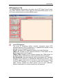
RTP Sessions Tab
The RTP Sessions tab provides information about RTP (Real Time Protocol
over UDP) sessions, which involve either the monitored BCM system or one
of IP sets controlled by the monitored BCM system.
Local IP Endpoints:
The Local IP Endpoints section contains information about RTP
sessions between local IP endpoints (i.e. endpoints that reside in local
subnets of the monitored BCM system).
IP to IP: Number of RTP sessions between two local IP devices.
TDM to IP: Number of RTP sessions between a TDM device on the
BCM system and a local IP device.
TDM to TDM: Number of RTP session between two TDM devices on
the BCM system (TDM devices cross-connected over an IP trunk).
Est. Bandwidth: Estimated network traffic generated by RTP sessions
between local IP devices or TDM devices and local IP devices. Only
the BCM system itself and/or IP devices on local subnets are involved
in these RTP sessions (i.e. no remote devices are involved). This
traffic directly impacts the BCM system and its local subnet(s).
Network connections to remote subnets are not impacted.
NN40011-030 Issue 1.2 BCM Rls 6.0
19
BCM Monitor
Local to Remote IP Endpoint:
The Local to Remote IP Endpoint section contains information about
RTP sessions between a local IP endpoint (i.e. an endpoint that resides
in local subnets of the monitored BCM system) and a remote IP
endpoint (i.e. an endpoint that resides outside of local subnets of the
monitored BCM system).
IP to IP: Number of RTP sessions between a local IP device and a
remote IP device.
TDM to IP: Number of RTP sessions between a TDM device on the
BCM system and a remote IP device.
Est. Bandwidth: Estimated network traffic generated by RTP sessions
between TDM devices or local IP devices and remote IP endpoints.
The BCM system itself and/or IP devices on local subnets are involved
in these RTP sessions, which are routed to remote devices. This traffic
directly impacts the BCM system and its local subnet(s) as well as
network connections to remote subnets.
Remote IP Endpoints:
The Remote IP Endpoints section contains information about RTP
sessions between remote IP endpoints (i.e. endpoints that reside
outside of local subnets of the monitored BCM system).
IP to IP: Number of RTP sessions between remote IP devices.
Est. Bandwidth: Estimated network traffic generated by RTP sessions
between remote IP endpoints. This traffic is generated on the route
between the remote IP devices and typically does not impact the
monitored BCM system.
Media Gateways:
The Media Gateways section contains information about allocated
media gateways. A media gateway is a logical entity that combines a
set of resources required for a single connection between a TDM
device and an IP endpoint.
Active (on call): Number of media gateways that are currently involved
in an active RTP session out of the number of allocated media
gateways.
RTP Session Details:
The RTP Session Details section contains detailed information about
active RTP sessions. For each active session, a single line is
presented in the following format:
{IP Endpoint A}{IP Trunk X}<stream info>{IP Trunk Y}{IP Endpoint B}
Codec FPP Details
The IP Endpoint tokens contain all available information about each IP
endpoint (type, DN, IP address, RTP port number). The IP Trunk tokens
contain information about the IP Trunk used by each endpoint (if no trunk is
used, the token is omitted). The stream info token shows which RTP streams
are enabled between the two endpoints. The Codec token described the
codec type used for the RTP session. The FPP shows the negotiated value of
20
NN40011-030 Issue 1.2 BCM Rls 6.0
BCM Monitor
“frames per packet”. The Details token shows additional information about the
RTP session.
BCM Monitor can display real time RTP session statistics for sessions that
involve at least one media gateway. These real time statistics include
information about the duration of the session, the number of bytes and
packets received/sent per second and the total number of bytes and packets
received/sent during the session. To display the RTP session real time
statistics, double-click the line with the RTP session. To hide the real time
statistics, double-click the line with the RTP session for the second time.
Universal ISDN Protocol Tab
The Universal ISDN Protocol (UIP) tab allows you to enable monitoring of
UIP messages associated with IP trunks (MCDN messages) and PRI modules
installed in the monitored BCM system.
UIP Modules:
The UIP modules section contains check boxes for all modules that can
be selected for UIP monitoring.
MCDN over IP: Enables/disables monitoring of MCDN over IP
messages for calls made over IP trunks.
PRI Module – Bus X: Enables/disables monitoring of UIP messages
for calls made over trunks provided by a PRI module on the selected
bus.
BRI Module – Bus X: Enables/disables monitoring of UIP messages
for calls made over trunks provided by a BRI module on the selected
bus.
NN40011-030 Issue 1.2 BCM Rls 6.0
21
BCM Monitor
Logging:
The Logging section allows you to enable logging of UIP messages.
Log UIP Data: Enables/disables logging of displayed UIP messages.
Timeout Settings:
UIP timeout: Display the amount of time after which monitoring of
selected UIP modules will be disabled.
Disable timeout: Allows you to override the UIP monitoring timeout.
Please use this option with caution.
Universal ISDN Protocol Messages:
The Universal ISDN Protocol Messages section displays a folder for
each UIP module that has been enabled. Within each folder, the
section displays up to 20 most recent UIP messages. UIP messages,
which contain at least one information element (IE), can be expanded
to show information elements. An IE, which contains data, can be
expanded to show the content of the data portion of the IE.
Each UIP message line contains the following information:
The direction in relation to the BCM system („>‟ for incoming, „<‟ for
outgoing)
The message type („CC‟ for call control, „MTC‟ for maintenance)
The direction in relation to the call reference origin („> Cref origin‟ for
incoming, „< Cref origin‟ for outgoing)
The message name (or a hexadecimal value if the name is unknown)
Additional data extracted from information elements
Note: Monitoring of UIP messages on a busy system may have a certain
impact on the performance of the BCM system or some peripherals connected
to the BCM system. For example, when IP sets or voice ports make/receive a
high number of calls over PRI trunks, monitoring of UIP messages increases
the amount of generated signalling data and could increase the response time
for IP sets and/or voice ports. For that reason, when monitoring a busy
system, monitoring of only a single UIP module at a time is strongly
recommended. Also, the monitoring time should be kept to minimum to limit
the impact. When investigating intermittent problems, an extended monitoring
period may be required. In such a case, use the Disable timeout check box in
the Timeout Settings section and enable logging of UIP data. You must
consider a potential impact on the system performance if the BCM system
handles a high number of PRI calls.
22
NN40011-030 Issue 1.2 BCM Rls 6.0
BCM Monitor
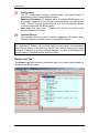
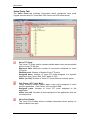
Line Monitor
The Line Monitor tab provides real time information about the state of all the
physical and voice over IP (VoIP) lines on the BCM.
Statistics:
The Statistics section contains details about the lines being monitored
by the BCM Monitor.
Active Lines: Number of lines that are not in the idle state.
Visible Lines:
The Visible Lines section contains controls that enable the
administrator to choose the lines that are displayed in the Line Monitor
list.
Show All Lines (including inactive): When checked, the Line Monitor
list will show the details about all the lines being monitored by the BCM
Monitor. When unchecked, the Line Monitor list will only display details
about the lines that have been used since the BCM was last rebooted.
Line Monitor:
This section shows the details about the BCM voice over IP (VoIP) and
physical lines. Lines numbered from 1 to 60 are VoIP lines. Lines
displayed in light grey represent lines that are idle. Blue lines represent
lines that are active and finally, red lines represent lines that are on
hold.
Line: Line number and line name.
NN40011-030 Issue 1.2 BCM Rls 6.0
23
BCM Monitor
Direction: Direction of the call present on the line Outgoing is shown
when the call originates from the BCM outward and Incoming is shown
when the call is originated from outside and directed at the BCM.
Start Time: BCM time and date at which the call started.
User: Shows the DN and Name of the BCM user that is involved in the
call.
State: Idle: No active call on the line. Dialing: BCM user in the process
of dialing the digits to place a call. The dialled digits appear in the
Number and Name as the user dials. Alerting: A call has been received
on the line and a BCM user‟s phone is ringing. Connected: The line has
a connected call. Held: The line has a held call.
Number and Name: Number and name of the far-end used involved in
the call.
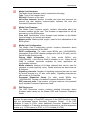
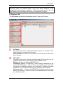
Usage Indicators Tab
The Usage Indicators tab provides real time information about the BCM
system, MSC Resources and certain types of telephony devices.
BCM Info:
The BCM Info section contains details about the BCM system‟s CPU
and memory usage.
CPU: The current usage on the BCM system‟s main CPU.
Physical Memory: Physical memory in use (out of the total installed
physical memory).
Non-paged Memory: Non-paged memory in use (out of the non-paged
memory pool).
24
NN40011-030 Issue 1.2 BCM Rls 6.0
BCM Monitor
Used Media Card Resources:
The Used Media Card Resources section contains details about the
Media Card‟s resource usage.
Signalling Channels: Current usage of Media Services Card‟s
signalling channels.
Media Channels: Current usage of Media Services Card‟s media
channels.
Voice Bus Channels: Current usage of Media Services Card‟s voice
bus channels.
DSP Resources: Current usage of DSP resources provided by
installed Processor Expansion Cards.
Active Telephony Devices:
The Active Telephony Devices section contains details about IP trunks,
IP sets, voice ports and media gateways.
IP Trunks: Number of active IP trunks (out of the number of booted IP
trunks).
IP Sets: Number of active IP sets (out of the number of booted IP sets).
Voice Ports: Number of active voice ports (out of the number of booted
voice ports).
Media Gateways: Number of active media gateways (out of the
currently allocated media gateways).
Note: Indicators are displayed in green when the usage appears to be normal.
A yellow indicator signals a potential resource problem. Further investigation
is recommended if an indicator remains yellow for an extended period of time.
A red indicator signals a critical resource problem. Further investigation is
recommended if an indicator remains red for more than a few seconds.
NN40011-030 Issue 1.2 BCM Rls 6.0
25
BCM Monitor
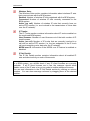
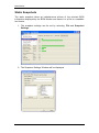
Static Snapshots
The static snapshot takes an instantaneous picture of the relevant BCM
information displayed by the BCM Monitor and saves it to a file in a readable
text format.
1. The snapshot settings can be set by selecting, File and Snapshot
Settings.
2. The Snapshot Settings Window will be displayed.
26
NN40011-030 Issue 1.2 BCM Rls 6.0
BCM Monitor
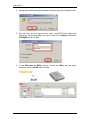
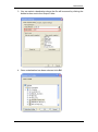
3. You can select a destination where the file will be saved by clicking the
builder button next to the Output Folder.
4. Once a destination has been selected click OK.
NN40011-030 Issue 1.2 BCM Rls 6.0
27
BCM Monitor
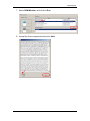
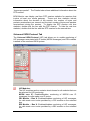
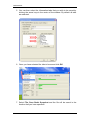
5. You can then select the information tabs that you wish to be saved by
clicking the arrow keys in the centre of the window. By default all tabs
are selected.
6. Once you have selected the tabs to be saved click OK.
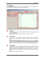
7. Select File, Save Static Snapshot and the file will be saved in the
location that you have specified.
28
NN40011-030 Issue 1.2 BCM Rls 6.0
BCM Monitor
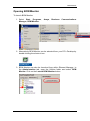
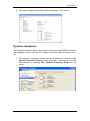
8. The static snapshot information will be displayed in text format.
Dynamic Snapshots
The dynamic snapshot takes a succession of pictures of the BCM information
that changes in time (such as CPU usage and active calls) and saves it to a
file.
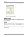
1. The dynamic snapshot feature can be activated by selecting File,
Dynamic Snapshot, Start from the menu bar. Conversely, it can be
de-activated by selecting File, Dynamic Snapshot, Stop from the
menu.
NN40011-030 Issue 1.2 BCM Rls 6.0
29
BCM Monitor
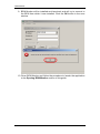
2. The dynamic snapshots can be set by selecting File, Snapshot
settings and selecting the Dynamic snapshot settings Tab.
3. The Snapshot Settings Window will be displayed.
4. The destination where the file will be saved can then be selected in the
same manner as previously described.
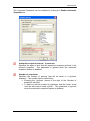
Automatic Snapshot
When enabled, the automatic snapshot tells the BCM Monitor application to
take multiple pictures of the BCM Monitor dynamic information in a single
dynamic snapshot file.
The number of pictures to take and the time interval between each picture is
configurable.
The dynamic snapshot will stop by itself when all the pictures are taken or it
can be stopped manually by selecting Files, Dynamic Snapshot, Stop from
the menu.
When disabled, the file resulting from a dynamic snapshot will contain a single
picture that represents the state of the dynamic information at the time the
snapshot was taken.
30
NN40011-030 Issue 1.2 BCM Rls 6.0
BCM Monitor
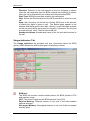
The Automatic Snapshot can be enabled by ticking the Enable Automatic
Snapshot box.
Automatic snapshot interval - In seconds:
Specifies the lapse of time that will separate successive pictures in the
dynamic snapshot. This parameter is ignored when the automatic
snapshot feature is disabled.
Number of snapshots:
Specifies the number of pictures that will be taken in a dynamic
snapshot. The number can be selected by:
Pressing the „up-down‟ arrows to the right of the “Number of
snapshot” edit field.
To select an infinite number of snapshots, hold the „down‟ arrow
until the edit control reads „Infinite‟. This parameter is ignored
when the automatic snapshot feature is disabled.
NN40011-030 Issue 1.2 BCM Rls 6.0
31
BCM Monitor
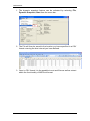
1. The dynamic snapshot feature can be activated by selecting File,
Dynamic Snapshot, Start from the menu bar.
2. The File will then be saved to the location you have specified in a CSV
format covering the time interval you have defined.
3. Once in CSV format it is the possible to sort and filter as well as extract
within the functionality of MS Excel format.
32
NN40011-030 Issue 1.2 BCM Rls 6.0
BCM Monitor
Avaya Documentation Links
Administration & Security Guide
NN40011-030 Issue 1.2 BCM Rls 6.0
33
BCM Monitor
34
NN40011-030 Issue 1.2 BCM Rls 6.0