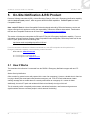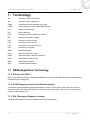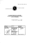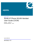
1
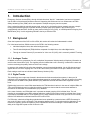
Business Communications Manager BCM 200, 400, 1000 > Technical Solution Guide for BCM Emergency Services Access (ESA) Enterprise Solution Engineering Document Date: November 16, 2006 Document Version: 2.2 Final Nortel Confidential Technical Solution Guide for BCM ESA v2.2 November 2006 Nortel is a recognized leader in delivering communications capabilities that enhance the human experience, ignite and power global commerce, and secure and protect the world’s most critical information. Serving both service provider and enterprise customers, Nortel delivers innovative technology solutions encompassing end-to-end broadband, Voice over IP, multimedia services and applications, and wireless broadband designed to help people solve the world’s greatest challenges. Nortel does business in more than 150 countries. For more information, visit Nortel on the Web at nortel.com. NORTEL NETWORKS CONFIDENTIAL: This document contains material considered to be proprietary to Nortel. No part of it shall be disclosed to a third party for any reason except after receiving express written permission from Nortel and only after securing agreement from the third party not to disclose any part of this document. Receipt of this document does not confer any type of license to make, sell or use any device based upon the teachings of the document. Receipt of the document does not constitute a publication of any part hereof and Nortel explicitly retains exclusive ownership rights to all proprietary material contained herein. This restriction does not limit the right to use information contained herein if it is obtained from any other source without restriction. Nortel Business Made Simple, Nortel, the Nortel logo, and the Globemark are trademarks of Nortel Networks. All other trademarks are the property of their owners. Copyright © 2006 Nortel Networks. All rights reserved. Information in this document is subject to change without notice. Nortel assumes no responsibility for any errors that may appear in this document. Disclaimer This engineering document contains the best information available at the time of publication in terms of supporting the application and engineering of Nortel products in the customer environment. They are solely for use by Nortel customers and meant as a guide for network engineers and planners from a network engineering perspective. All information is subject to interpretation based on internal Nortel test methodologies which were used to derive the various capacity and equipment performance criteria and should be reviewed with Nortel engineering primes prior to implementation in a live environment. _______________________________________________________________________________________________________________________ 1 Nortel Confidential Technical Solution Guide for BCM ESA v2.2 November 2006 Abstract Nortel’s Business Communication Manager (BCM) extensive suite of telephony features is complemented by range of options in support of Emergency Services Access (ESA). This document contains architectural and system level programming information intended to assist the user in the selection and implementation of an ESA strategy which is appropriate to their jurisdiction. It should be clearly understood that the information contained herein is intended for an audience which is BCM literate, informed and experienced. Making appropriate ESA choices requires detailed knowledge of your local laws and telephony governance practice. This document does not supersede local regulations nor does it replace the detailed research required for the proper design of ESA architecture. Remember to refer to your local laws, regulations, and practices for ESA implementation. Revision Control No Date Version Revised by Remarks 1 2006.05.29 1.0 Pierre Fournier Initial Version, Mark Fletcher, JP Ruprecht, and Pierre Fournier 2 2006.08.03 1.1 Pierre Fournier Incorporated field input and corrections 3 2006.11.14 2.0 Pierre Fournier Release Version 4 2006.11.14 2.1 Pierre Fournier Final version _______________________________________________________________________________________________________________________ 2 Nortel Confidential Technical Solution Guide for BCM ESA v2.2 November 2006 TABLE OF CONTENTS 1. INTRODUCTION ...............................................................................................................................6 1.1 Background...................................................................................................................................................6 1.1.1 Analogue Trunks.....................................................................................................................................6 1.1.2 Digital Trunks..........................................................................................................................................6 1.1.3 IP Trunking .............................................................................................................................................7 1.2 Reference ESA Call Flow .............................................................................................................................7 1.3 ESA on BCM..................................................................................................................................................8 1.3.1 CAPEX & OPEX Considerations ............................................................................................................9 1.4 BCM ESA Models..........................................................................................................................................9 1.5 Implementation Steps ..................................................................................................................................9 2. MAIN DN .........................................................................................................................................10 2.1 Applicability ................................................................................................................................................10 2.2 How It Works ...............................................................................................................................................10 2.3 Main DN Setup ............................................................................................................................................11 3. LOCATION ORIENTED DNS..........................................................................................................12 3.1 Applicability ................................................................................................................................................12 3.2 How it works................................................................................................................................................12 3.3 BCM Setup...................................................................................................................................................13 3.3.1 Trunk Selection & Location Engineering ..............................................................................................13 3.3.1.1 Initial Conditions ...............................................................................................................................13 3.3.1.2 ESA Modifications.............................................................................................................................14 3.3.1.3 Setup Sequence ...............................................................................................................................14 3.3.2 Trunking Summary Table .....................................................................................................................15 3.3.3 Paper records to store information .......................................................................................................15 3.3.4 Detailed BCM Setup Information (screen captures).............................................................................15 3.3.4.1 Setup of Location Trunks..................................................................................................................15 3.3.4.2 Emergency Phone (red phone) ........................................................................................................20 3.3.4.3 Autodial for Emergency Phone.........................................................................................................22 4. 4.1 ENGINEERING CONSIDERATIONS & SPECIAL CASES ............................................................24 IP Sets ..........................................................................................................................................................24 4.2 Softclients, Wireless, and Teleworking ....................................................................................................24 4.2.1 Main DN ................................................................................................................................................24 4.2.2 Location Based DNs .............................................................................................................................25 4.2.3 DID – PRI Trunks..................................................................................................................................25 _______________________________________________________________________________________________________________________ 3 Nortel Confidential Technical Solution Guide for BCM ESA v2.2 November 2006 4.3 Survivable Remote Gateway (SRG) ..........................................................................................................25 4.3.1 Normal Mode Operation .......................................................................................................................25 4.3.2 Survivable Mode Operation ..................................................................................................................25 4.4 5. BCM & International ESA Dialing..............................................................................................................26 ON-SITE NOTIFICATION & RSI PRODUCT ..................................................................................28 5.1 How It Works ...............................................................................................................................................28 5.1.1 Centralized Security Notification...........................................................................................................29 5.2 RSI Light Installation ..................................................................................................................................29 5.2.1 Enable the Emergency/E911 Notification option ..................................................................................29 5.2.2 Emergency Options ..............................................................................................................................30 5.2.2.1 Define Emergency Numbers to be recognized by the system .........................................................30 5.2.2.2 Define Notification Extensions ..........................................................................................................30 6. EMERGENCY TELEPHONE CONNECTIVITY TO ANALOG TRUNK...........................................31 7. TERMINOLOGY ..............................................................................................................................32 7.1 NENA Regulations Terminology ...............................................................................................................32 7.1.1 Enhanced 911 (E911)...........................................................................................................................32 7.1.2 ELIN (Emergency Location Identification Number) ..............................................................................32 7.1.3 ERL (Emergency Response Location) .................................................................................................32 _______________________________________________________________________________________________________________________ 4 Nortel Confidential Technical Solution Guide for BCM ESA v2.2 November 2006 List of Figures Figure 1: BCM ESA Reference Topology.................................................................................................................. 8 Figure 2: Location Based LDNs Topology............................................................................................................... 13 Figure 3: BCM Media Bay Module Resources ........................................................................................................ 15 Figure 4: BCM Trunks.............................................................................................................................................. 16 Figure 5: BCM Incoming Trunk Programming......................................................................................................... 17 Figure 6: BCM Line Pool “A” Assignment................................................................................................................ 18 Figure 7: Line Pool B Assignment ........................................................................................................................... 19 Figure 8: Line Pool Access Codes .......................................................................................................................... 20 Figure 9: ESA Phone Line Assignment ................................................................................................................... 21 Figure 10: ESA Phone Set Assignment................................................................................................................... 22 Figure 11: ESA Phone Autodial Programming ........................................................................................................ 23 Figure 12: International ESA Number – 1 ............................................................................................................... 26 Figure 13: International ESA Number - 2 ................................................................................................................ 27 Figure 14: RSI Screen Capture ............................................................................................................................... 29 Figure 15: RSI Feature Enabling ............................................................................................................................. 30 Figure 16: RSI Setup: Notification DNs ................................................................................................................... 30 List of Tables Table 1: BCM ESA Model Selection.......................................................................................................................... 9 Table 2: Trunking Summary .................................................................................................................................... 15 _______________________________________________________________________________________________________________________ 5 Nortel Confidential Technical Solution Guide for BCM ESA v2.2 November 2006 1. Introduction Emergency Services Access (ESA), through its North American “dial 911” instantiation, has become integrated into the fabric of the telecommunications network. Supporting this lifeline service is an infrastructure of Public Safety Answering Point (PSAP) which can respond to multiple emergency service requests. Once a subscriber dials the requisite access code, such as 911, the hosting telecom network executes a simple routing process based upon the origination Directory Number (DN) which results in the call arriving at a geographically relevant PSAP. Known by many names Calling Line ID (CLID), or in BCM speak the Outgoing Line Identification (OLI), it is this originating DN that is the key to effective ESA. 1.1 Background Given the importance of the CLID or OLI to ESA, this section will review the fundamentals involved. For Voice based services, BCMs connect to the PSTN in the following manner: • Individual telephone lines, also called analogue trunks • Time Division Multiplexed (TDM) facilities composed of multiple lines, also called digital trunks • Through an Internet Protocol (IP) connection for Voice over IP (VoIP), this is commonly called IP Trunking 1.1.1 Analogue Trunks In addition to the voice component of a call, a telephone line passes a limited quantity of telephony information to and from the Central Office (CO). The signaling used to indicate that a call is incoming, is electrical in nature and involves monitoring the polarity and level of the line’s voltage. In essence, this method will only allow the subscriber communicate the digits dialed; it is the CO that stores and applies the line’s CLID to outgoing call. This CLID is then used by the PSAP to look-up the address of the caller. Each analogue trunk has an individual Listed Directory Number (LDN). 1.1.2 Digital Trunks This technology was a major step forward in the advanced of telecommunications systems, in that up to 24 individual voice conversations can be digitized and transported on a single facility. And with the advent of trunking protocols such as ISDN Primary Rate Interface (PRI), additional services and features are supported over the trunk. Digital trunks have one or more LDNs associated to the TDM timeslots it carries. In the case of multiple LDNs, the Telco and ESA Authority work in conjunction with the customer to ensure that the correct street address is recorded in the Automatic Line Identification (ALI) database. In the case of a basic, non-PRI digital trunk, it operates as simple grouping of 24 individual lines. The call signaling is accomplished via multiple schemas which are variants of the method used for individual lines. Known by names such as E&M and Per Trunk Signaling (PTS), these methods continue to rely upon the CO to correctly add the CLID defined for individual timeslot on the trunk for ESA. For PRI trunks, electrical call signaling methods have been replaced by a protocol where a SETUP message is sent to the CO when a call is originated. This messaging based system, in conjunction with the dedication of one timeslot for signaling, permit an expansion of the information that can be exchanged. This translates into the ability of the originator to pass on their CLID to the CO. _______________________________________________________________________________________________________________________ 6 Nortel Confidential Technical Solution Guide for BCM ESA v2.2 November 2006 1.1.3 IP Trunking The introduction of VoIP heralds a new phase in the evolution of telecommunications; users can now leverage the ubiquity of IP networks to be connected almost anywhere and at any time. This mobility of IP telephone and softclients, create a new set of challenges for ESA as a user’s location can change as dynamically as their IP address. This is an industry wide issue, and suppliers are adapting an evolving their approach to ESA. BCM specific recommendations are contained within this document. 1.2 Reference ESA Call Flow This section explains a general emergency services model as it relates to PBX systems and emergency calls. The following steps explain the progress of a 911 call from initiation through to PSAP answering. 1. A PBX station initiates a 911 call. 2. The PBX will initiate the call on a trunk to the Telco central office. In the case of analog trunks, the calling number is the line associated with the analog trunk that was seized for the 911 call. In the case of digital trunks, the calling number may be passed along by the PBX to the central office. 3. The central office will route the call to the PSAP. A Caller’s Emergency Service Identification number (CESID) will be passed along with the call to the PSAP. The CESID sent to the PSAP will depend upon how the methodology the Telco uses to pass this information over to the PSAP: a. In the case of analog trunk call from the PBX, this will be the calling number of the trunk. b. In the case of digital trunk call from the PBX with direct inward dial (DID) numbers, this may be the calling number signaled over the trunk from the PBX c. In the case where a PBX passes non-DID extension numbers to the central office, this may be a mapping of extension numbers to a DID number on the PBX. Or, the PBX will provide a CLI number which represents an externally dialable number that is in close proximity to the calling non-DID number. 4. The PSAP receives the call and an Automatic Location Identification (ALI) lookup is performed which maps the CESID to a physical location. Note that the CESID is not only used to provide a physical location of the emergency for dispatching emergency crews but also provides the call back number for the 911 agent in the case of emergency call disconnection. _______________________________________________________________________________________________________________________ 7 Nortel Confidential Technical Solution Guide for BCM ESA v2.2 November 2006 Emergency Services Access Model Any station 911 Agent position Jun e 09 10:49 A CFW D Meridian User dials 911 1 Calling Number (ANI) 911 call Central Office (Local Telco) Callers Emergency Service Identification (CESID) Location information (from ALI) Voice call 4 3 2 Lookup Public Safety Answering Point (PSAP) Location database (ALI) NORTEL CONFIDENTIAL Provided under a Non Disclosure Agreement Page 20 Figure 1: BCM ESA Reference Topology As can be seen, the mapping of the ANI by the PBX and Telco to provide a CESID to the PSAP can be provided by either: • PBX provides appropriate calling number that has a corresponding PSAP ALI entry and the Telco passes this calling number through • Central office can provide mapping between the calling number provided by the PBX to an appropriate CESID that has an ALI entry 1.3 ESA on BCM Nortel’s Business Communication Manager (BCM) works within the overall ESA framework to ensure transparency to the end-user within the working environment of a Private Branch Exchange (PBX). Specifically, the feature rich environment of BCM provides an adaptive foundation for ESA: • flexible emergency dialing codes • line identification (OLI) • on-site notification1 The BCM’s business model starts at the Key System level (< 10 extensions), and grows well into the traditional PBX market (< 100 extensions). This tenfold difference in user base is often translated into significantly different CAPEX and OPEX practices. 1 This functionality is provided through Nortel’s agreement with its Developer Partner Resource Software International (RSI) _______________________________________________________________________________________________________________________ 8 Nortel Confidential Technical Solution Guide for BCM ESA v2.2 November 2006 1.3.1 CAPEX & OPEX Considerations Financial pressures on the smaller SMB deployments may limit ESA options due to the added cost of implementing and operating single purpose call back lines, or the over-provisioning of access trunks. It can be anticipated that any ESA installation will be governed by legislation and: • Initial cost of purchasing new equipment • Setup costs associated with new phone service • Ongoing expense of additional infrastructure 1.4 BCM ESA Models This section is intended to assist the reader in the selection of an appropriate method of servicing ESA calls on the BCM. It is not intended to supersede or interpret local regulation and laws. As previously discussed, the originating line information is the index used for ALI at the PSAP. Independently of the PBX’s Dial Access Model, the line information is limited to a number of sources. The following table introduces a number of BCM Site ESA Operation Models that build upon the origin of the line information. By indexing your PBX Dial Access method (Direct Inward Dial (DID), or non-DID), and further refining the selection to incorporate the types of trunks connecting to the PSTN, the reader can identify the recommended BCM Site ESA Operation Model. For clarity, the following convention will be used: • LDN: the Listed Directory Number for the enterprise, also known as the Primary DN • OLI: Outgoing Line Identification, the BCM’s name for Calling Line ID (CLID) information pushed to the PSTN PBX Dial Access Model non-DID DID BCM to PSTN Interconnect analogue trunk digital trunk Is OLI Supported on Trunk? N N BCM Site ESA Which DN is ALI Lookup Information Operation Model Source Options Used for ALI LDN LDN LDN Telco records for LDN Telco records for LDN PRI trunk Y OLI - CLID analogue trunk N digital trunk N LDN LDN PRI trunk Y originating line OLI Originating DN CLID Main DN Main DN Main DN, Location based DNs Main DN Telco records for LDN Telco records for LDN Implementation Notes must set all OLI to Main DN or Location DNs requires FEM + Nor* TM + DID Line Card for incoming calls, outgoing require additional analog trunk facilities Main DN call back to originating line, no additional steps required Table 1: BCM ESA Model Selection 1.5 Implementation Steps • Research and understand all relevant ESA legislation & regulation applicable to your specific area _______________________________________________________________________________________________________________________ 9 Nortel Confidential Technical Solution Guide for BCM ESA v2.2 November 2006 • Follow table 1 to identify what are the models relevant to your installation • Perform cost/benefit analysis of the Nortel Developer Partner RSI tools CTI pack product for your installation • Work with hosting Telco to develop Evening & Weekend call-back protocol 2. Main DN This configuration best typifies the Private Branch Exchange (PBX) access model: a single public telephone number is multiplexed into every extension in the office. A primary or main Directory Number (DN) is assigned to the Enterprise, and is typically terminated at an attendant hosted station. In this mode, the challenge for delivering ESA is to: • Provide notification to the attendant of ESA telephone activity • Ensure a call back path to the enterprise for the ESA operator • Respect SMB constraints of small infrastructure budgets 2.1 Applicability Main DN ESA Operation Model applies to: • Non-DID, with analogue trunks to the PSTN • Non-DID, with digital trunks to the PSTN • DID, with analogue trunks to the PSTN • DID, with digital trunks to the PSTN In addition, it may also apply to: • Non-DID, with PRI trunking to the PSTN 2.2 How It Works When an enterprise purchases one or more trunks from a local Telephony Service Provider the Listed DN (LDN) is mapped against a street address for lookup by the PSAP during an ESA call. The CLID of the trunk is the index into this database, and its delivery to the PSAP is ensured by the Telco, as analogue or non-PRI digital trunks can not supply originating CLID information during a call. In either case, the Enterprise may choose to have a single LDN and multiple non-listed DNs associated with the PSTN trunk connections. However, it is critical that the final combination of LDN and DN provide a means for a call back from the ESA operator. In some cases a PBX may only send a main listed directory number to the central office. In this case, the PSAP will have a single location for all the CESID and all 911 calls originating on the PBX will have this as the emergency response location (ALI). Also, in the case of emergency callback (in case of disconnection), the main directory number is called back (not the actual telephone originating the emergency call). This may be adequate where there is a single building with a single floor and a small number of people. This becomes less adequate as the physical size of a location grows, as there are an increasing number of phones at the location and/or there are multiple floors. _______________________________________________________________________________________________________________________ 10 Nortel Confidential Technical Solution Guide for BCM ESA v2.2 November 2006 One way to address this type of setup is by having on-site notification of emergency calls. In this way, when a 911 call is originated on a PBX, the answering attendant at the main directory number can also be notified of the emergency call and the internal extension number it originated on. The attendant can have a location to extension number map so that they are aware of who originated the emergency call and where they are located. In this way, if there is a loop disconnect and callback by the PSAP, the person receiving the callback will be aware of the emergency and location. They can also direct emergency crews to the actual location of the emergency. BCM is able to provide a single main directory number for emergency calls for the case where this adequately addresses the emergency calling requirements. BCM also supports on-site notification through the use of the RSI tools CTI Pack product, which has been developed by a Nortel Developer Partner RSI. The RSI tools CTI Pack supports 911 emergency notifications. Using this solution, an instant warning message with an audible alarm can be sent to a security station when an emergency 911 number is dialed and identifies the origin of this call and optionally alerting to a designated telephone set. However, BCM does not support “on-box” on-site notification of attendant, an attendant with a PC and the Nortel Developer Partner RSI solution are required. 2.3 Main DN Setup For this ESA Site Option, the bulk of the setup is performed at the Central Office where the mapping of the Listed DNs to the appropriate CESID is performed. Within tables on the host switch, the Telco will map each trunk DN to a CESID for which the PSAP location records clearly identify the SMB. For example: • An SMB has purchased 4 trunks as follows: o Trunk 1: incoming, listed DN 555-5200 o Trunk 2: incoming, listed DN 555-5201 o Trunk 3: outgoing, listed DN 555-5202 o Trunk 4: outgoing, listed DN 555-5203 Thus an ESA call placed from an extension served by these trunks would arrive at the Central Office and identified as either 555-5202 or 555-5203 (depending on which trunk is seized for the call). To endure that PSAP correctly identifies the origins of the call, the Central Office table datafill will map the CESID of 555-5200 to all four of the trunk DNs or maintain four separate, but identical, entries. For example, a 911 call placed from 555-5203, will arrive at the PSAP with a CESID of 555-5200 which will pull up the correct location information for our SMB. _______________________________________________________________________________________________________________________ 11 Nortel Confidential Technical Solution Guide for BCM ESA v2.2 November 2006 3. Location Oriented DNs This technique consists of leveraging the DNs associated with analogue and digital trunks by making specific LDN to location mappings. What is intrinsically confusing is the concept that these installations do not support DID, and that we will be overlaying some rules that will affect some basic routing of calls based upon the LDN. In this method, telephones are grouped together based upon physical location; they are assigned to specific LDNs, which is mapped by the Telco to a unique Emergency Response Location. For example, the sets on a particular floor of a building can be considered an emergency response location with adequate granularity. 3.1 Applicability Location Oriented DNs ESA Operation Model may apply to: • Non-DID, analogue trunks to the PSTN • Non-DID, digital trunks to the PSTN 3.2 How it works Let us examine the case of an Enterprise that has two distinct locations within one complex: a main office and a second floor with a separate entrance (see Figure 2: Location Based LDNs Topology). There is a main LDN for the Enterprise, and multiple LDNs associated with the additional Analog or Digital Trunks that connect the PBX to the PSTN; it is also assumed that the each incoming trunk appears at a centralized attendant position. The sets associated with the second floor, can be routed to specific outgoing trunks that have LDNs with a separate CESID from the first floor. In this way; a PSAP ALI lookup will return a different street address from the main location. Incoming calls to the second floor trunks can still be routed to a centralized attendant position, however for ESA callback purposes they should also appear upon a dedicated telephone set that is located in the Warehouse location. The assumption is that during office hours the attendant will pick-up ESA call back and route it to the second floor; outside of business hours, the call back would terminate on a dedicated emergency phone on the second floor. On-site notification applications running at the main attendant position, is also useful. _______________________________________________________________________________________________________________________ 12 Nortel Confidential Technical Solution Guide for BCM ESA v2.2 November 2006 Central Office Incoming Line ESA Telco OLI = 555-5203 LDN = 555-5203 Line 124 Outgoing Trunk Telco OLI = 555-5206 LDN = 555-5203 Line 123 Outgoing Trunk Telco OLI = 555-5207 LDN = 555-5203 Line 122 Outgoing Trunk Telco OLI = 555-5204 LDN = 555-5200 Outgoing Trunk LDN = 555-5205 Telco OLI = 555-5200 Incoming Trunk LDN = 555-5200 Telco OLI = 555-5200 Incoming Trunk LDN = 555-5201 Telco OLI = 555-5200 Incoming Trunk LDN = 555-5202 Telco OLI = 555-5200 Line 121 Line 94 2nd Floor Emergency Phone LDN: 555-5203 DN: 365 DN: 230 BCM Line Pool C 2nd Floor ONLY Access code: 8 DN: 227 DN: 225 DN: 226 DN: 228 DN: 231 DN: 232 DN: 229 DN: 226 BCM Line Pool A 1st Floor ONLY Access Code: 9 DN: 224 DN: 221 DN: 222 DN: 223 Line appearances 555-5200 555-5204 555-5201 555-5205 555-5202 555-5206 555-5203 555-5207 Office Attendant: DN: 237 Line 91 Line 92 Line 93 Figure 2: Location Based LDNs Topology 3.3 BCM Setup In this chapter, the examples refer to Figure 2: Location Based LDNs Topology. 3.3.1 Trunk Selection & Location Engineering Each customer installation will have its own specifics that will dictate the final look and layout of a Location Based DN implementation. What are important to capture are the initial criteria, and the operational values which will shape the final design. A typical two floor layout will be used to develop this example. The expected outcome of this technique is to have two separate CESIDs mapped to the SMB: one per physical location. To achieve this, the sets on each floor will be funneled to specific outgoing trunks whose DNs will be associated with the correct physical location. 3.3.1.1 Initial Conditions Our SMB has purchased the following Telephony Services from its Telco: • The SMB’s Primary DN is the LDN of 555-5200 • Four Incoming Analogue trunks, which have different LDNs, Primary DN hunts across all three trunks : • o I/C trunk 1: 555-5200 o I/C trunk 2: 555-5201 o I/C trunk 3: 555-5202 o I/C trunk 4: 555-5203 Four Outgoing Analogue trunks, which have different LDNs: _______________________________________________________________________________________________________________________ 13 Nortel Confidential Technical Solution Guide for BCM ESA • 3.3.1.2 v2.2 o O/G trunk 1: 555-5204, ESA record points to SMB street number & Floor 1 o O/G trunk 2: 555-5205, ESA record points to SMB street number & Floor 1 o O/G trunk 3: 555-5206, ESA record points to SMB street number & Floor 2 o O/G trunk 4: 555-5207, ESA record points to SMB street number & Floor 2 November 2006 All outgoing trunks are mapped to a single Line Pool on the BCM. ESA Modifications There are two main BCM changes that are required to implement the Location Based DN: • Identify trunks that are specific to the 2nd floor & map the appropriate sets to a new pool • Add a new Emergency telephone line (red phone) to the 2nd floor for ESA callback. Note that with separate pools, and access codes, the two groups of users within the Enterprise will dial different digit sequences for 911 services: • Floor 1: 9-9-1-1 • Floor 2: 8-9-1-1 To reduce the potential for confusion, it is recommended that the phones be labeled with the appropriate 911 dialing sequence. 3.3.1.3 • • • Setup Sequence Create new line pool for floor #2, and map outgoing trunks to it o O/G trunk 3: 555-5206, ESA record points to SMB street number & Floor 2 o O/G trunk 4: 555-5207, ESA record points to SMB street number & Floor 2 Define set to outgoing Line Pool mapping o O/G trunk 1: 555-5204, is mapped to Pool A (floor 1), access code “9” o O/G trunk 2: 555-5205, is mapped to Pool A (floor 1), access code “9” o O/G trunk 3: 555-5206, is mapped to Pool B (floor 2), access code “8” o O/G trunk 3: 555-5207, is mapped to Pool B (floor 2), access code “8” Add new incoming line for emergency red phone on second floor (Callback requirement). It is a good practice to have this set configured as a 911 autodial line. o Incoming trunk 555-5203 is dedicated to the 2nd Floor Emergency Phone. o Telco is instructed to update the ESA records to provide a new location: 2nd floor o O/G trunk 2: 555-5206, SMB Street Address, 2nd Floor O/G trunk 3: 555-5207, SMB Street Address, 2nd Floor 2nd floor ESA Line: 555-5203, SMB Street Address, 2nd Floor It is a good practice to install a distinctive telephone to terminate the new 2nd Floor Emergency Line: Typical Emergency Phone: red colored, wall mount telephone set with appropriate signage “Emergency User ONLY” Setup an autodial to the appropriate Emergency DN (911); place appropriate signage to indicate (“Caution, 911 autodial) _______________________________________________________________________________________________________________________ 14 Nortel Confidential Technical Solution Guide for BCM ESA v2.2 November 2006 3.3.2 Trunking Summary Table This is a layout of DNs, trunks, and line pools. In addition, potential BCM line numbers and line pool access codes have been overlaid. LDN 555-5200 555-5201 555-5202 555-5204 555-5205 555-5206 555-5207 555-5203 Incoming OLI DN Outgoing 555-5200 I 555-5200 I 555-5200 I 555-5203 O 555-5200 O 555-5200 O 555-5203 O 555-5203 I/O Line 91 92 93 94 121 122 123 124 Assigment Attendant' set Attendant' set Attendant' set Pool A - access code 9 Pool A - access code 9 Pool B - access code 8 Pool B - access code 8 Emergency phone DN Notes 1st floor out line 1st floor out line 2nd floor out line 2nd floor out line 2nd floor Emergency Phone Line Table 2: Trunking Summary 3.3.3 Paper records to store information It is good practice to document and store the details of the any ESA topology that is put in place. 3.3.4 Detailed BCM Setup Information (screen captures) The screen captures in this section are meant for illustrative purposes only in order to provide the reader with an example, and are not a prescriptive method for implementation. The reader is reminded that there are many ways to complete the setup and programming of this solution, what is shown below is but one. Initially, the BCM must be equipped with the appropriate trunk and station modules. In the example below, bus positions 5, 6, and 7 contain two CLID Trunk Modules, and a Digital Station Module. In fact, it is a 4x16 Combo in bus 6 & 7. Figure 3: BCM Media Bay Module Resources 3.3.4.1 Setup of Location Trunks For this example, eight trunks are available for assignment (see below). They will be allocated as per Table 2: Trunking Summary. _______________________________________________________________________________________________________________________ 15 Nortel Confidential Technical Solution Guide for BCM ESA v2.2 November 2006 Figure 4: BCM Trunks From the allocation in Table 2: Trunking Summary line 091 is incoming, and should remain as a public line. _______________________________________________________________________________________________________________________ 16 Nortel Confidential Technical Solution Guide for BCM ESA v2.2 November 2006 Figure 5: BCM Incoming Trunk Programming Accordingly, lines 121 and 123 are assigned to pools A & B respectively. _______________________________________________________________________________________________________________________ 17 Nortel Confidential Technical Solution Guide for BCM ESA v2.2 November 2006 Figure 6: BCM Line Pool “A” Assignment _______________________________________________________________________________________________________________________ 18 Nortel Confidential Technical Solution Guide for BCM ESA v2.2 November 2006 Figure 7: Line Pool B Assignment The final step is to associate a dial code to each pool. One consequence of using different line pools for each floor is that there will be multiple dial codes for trunk access. In this example, the sets on the second floor, which will be using the Pool B, will be dialing “8” to dial out while the people on the 1st floor will be using “9”. _______________________________________________________________________________________________________________________ 19 Nortel Confidential Technical Solution Guide for BCM ESA v2.2 November 2006 Figure 8: Line Pool Access Codes 3.3.4.2 Emergency Phone (red phone) It is recommended that a dedicated telephone be located in the secondary location, and that it be identified as the ESA, or Emergency, phone. Typically red in color, this type of Emergency telephone set has become a common sight in workplaces. In this solution, this dedicated telephone will be reached by the PSAP Operator during an emergency related callback. In essence, its LDN is associated to the location based trunks which service this location. Configuration of this set is fairly simple in that it is a public line that terminates on a specific set. Details are in Figure 9: ESA Phone Line Assignment. _______________________________________________________________________________________________________________________ 20 Nortel Confidential Technical Solution Guide for BCM ESA v2.2 November 2006 Figure 9: ESA Phone Line Assignment _______________________________________________________________________________________________________________________ 21 Nortel Confidential Technical Solution Guide for BCM ESA v2.2 November 2006 Figure 10: ESA Phone Set Assignment 3.3.4.3 Autodial for Emergency Phone If the SMB wishes to ensure that this line is dedicated to Emergency use only, the BCM’s Hotline feature can be used. This will ensure that once the handset is lifted on the set, 911 is automatically dialed. Setup is completed in the Capabilities and Preferences TAB for the individual set: _______________________________________________________________________________________________________________________ 22 Nortel Confidential Technical Solution Guide for BCM ESA v2.2 November 2006 Figure 11: ESA Phone Autodial Programming _______________________________________________________________________________________________________________________ 23 Nortel Confidential Technical Solution Guide for BCM ESA v2.2 November 2006 4. Engineering Considerations & Special Cases 4.1 IP Sets For IP sets, the approaches previously described can be used as well as have a range of DNs associated with a physical area in a building and a physically nearby DID associated with this range. One of the flexibilities associated with installing IP sets on a LAN is to simplify administration by having these sets plug into a LAN and be dynamically allocated an IP address. These IP sets and clients can be easily moved around the building, plug into the LAN at different points and there is manual administration required to keep the physically nearby DID for emergency purposes up to date. Many times this information will be out of date and this is a significant challenge from an administrative perspective. BCM does not specifically support a capability specific to IP sets, IP subnet allocation and location DIDs for emergencies. This capability does exist on CS1K 4.2 Softclients, Wireless, and Teleworking Mobility has become a staple of the modern work environment; BCM offers three solutions that add flexibility to work place. For the remainder of this section, telephony originated from softclients, wireless sets, or from Telework locations shall be referred to as mobile user. Nortel’s i2050 softphone is an IP client that transforms a user’s USB headset equipped desktop into a telephony equipped office. Its true value lies in its ability to allow portable workstations to be telephony functional just about anywhere. BCM has a proven history, and an imbedded customer base, of wireless deployments which provide users with portability within the SMB. Firstly, customers select from a digital or WLAN (DECT & Spectralink) based solution, and then proceed to deploy access points to maximize coverage. Often, Nortel branded wireless sets attached to belt clips is the most visible sign of a BCM deployment! In many countries, Teleworking has become both a reality and a legislated requirement. BCM offers a full suite of Teleworking supportive technology which allows the user a form of workplace transparency. From an ESA perspective, care must be taken to ensure that mobility does not create confusion for Emergency Response Personnel. This section will look at the use of softclients, wireless, and Teleworking within the three BCM Site ESA Operation Models proposed in Table 1: BCM ESA Model Selection. 4.2.1 Main DN This model leverages the Telco records associated to the SMB’s LDN to determine the geographical location. This association is a consequence of the trunking characteristics and is independent of the SMB’s deployment topology. Thus, an ESA call placed from a mobile user, will display at the PSAP as if it is originated at the SMB’s street address of record. For on-site users, such as those using a wireless handset or soft clients, PSAP call back will be to the SMB’s main number and any emergency personnel will be dispatched to the correct street address. For SMBs with a large surface area, it may be beneficial to employ the Nortel Developer Partner RSI tools CTI pack product for 911 emergency notification, as it may be beneficial for some form of internal emergency response to be triggered immediately upon an ESA call being placed. Specifically, a search or other form of response may need to be undertaken. Off-site users will need to be instructed not to dial ESA from their SMB VoIP connection, as this will provide incorrect location information to the PSAP. This is a challenge for the industry and is not unique to the BCM. It is recommended that for any customers using VoIP for remote access, that the Nortel Developer Partner RSI tools CTI pack product be deployed. _______________________________________________________________________________________________________________________ 24 Nortel Confidential Technical Solution Guide for BCM ESA v2.2 November 2006 4.2.2 Location Based DNs Mobile users within an enterprise using this technique should take care to map the softclient or wireless set to the appropriate Line Pool servicing the geographic area in which it is deployed. For further information, please consult section 3.3.4.1 Setup of Location Trunks. Off-site users will need to be instructed not to dial ESA from their SMB VoIP connection, as this will provide incorrect location information to the PSAP., This is a challenge for the industry and is not unique to the BCM. It is recommended that for any customers using VoIP for remote access, that the Nortel Developer Partner RSI, tools CTI pack product be deployed for 911 emergency notification. 4.2.3 DID – PRI Trunks In this case, all telephony devices will be given a unique DID LDN that will be used for ALI. Again, for any in-SMB static mobile users, there are no special recommendations. Off-site users will need to be instructed not to dial ESA from their SMB VoIP connection, as this will provide incorrect location information to the PSAP. This is a challenge for the industry and is not unique to the BCM. It is recommended that for any customers using VoIP for remote access, that the Nortel Developer Partner RSI, tools CTI pack product be deployed for 911 Emergency Notification. In addition, here are a few recommendations that may help guide the SMB in making an appropriate choice for Teleworkers: • Assign the SMB’s primary DN to any softclient that will/may be used via remote access. This will ensure that any off-site originated ESA call backs get routed to the SMB’s principal attendant position. • Leave the i2050’s OLI information blank. Depending upon the local Telco & PSAP setup, this may trigger an ALI failure (similar to cell phones), which will prompt the PSAP operator to immediately ask the ESA caller to identify their physical location. 4.3 Survivable Remote Gateway (SRG) The Nortel SRG solution utilizes standard BCM 50 and BCM 200/400 hardware to provide a resilient survivable environment for the smaller remote branch office for IP sets. This is accomplished by activating a special SRG Keycode on the BCM. The SRG operates quite differently than a normal BCM, but is quite useful in providing local ESA/E911 trunking presence, in addition to its survivability capabilities. The SRG can provide both POTS and PRI trunking service and can support DID operation. 4.3.1 Normal Mode Operation When in Normal Mode, when the WAN is available, IP sets send their initial TPS registration requests to the SRG, where they are immediately redirected to the main CS1000 Call Server. IP sets then register against the main CS1000 where they get their profile like any other IP set in the network. Standard CS1000 IP Set Zone attributes are then applied, that contain the proper programming to detect and redirect ESA/E911 calls to the SRG for call routing. See the Nortel Emergency Services NTP for further detail on CS1000 ESA Zone provisioning to direct ESA/E911 calls to a remote trunking gateway. 4.3.2 Survivable Mode Operation In the event of a WAN failure, the IP Sets watchdog timer will expire, and the IP Sets will reboot. In this case when the initial registration request is sent to the SRG, the request is not redirected, and the IP Set will receive a profile from the SRG directly. The SRG only provides basic call capabilities such as: • Line Appearance _______________________________________________________________________________________________________________________ 25 Nortel Confidential Technical Solution Guide for BCM ESA • Call Termination • Conference • Hold • Transfer v2.2 November 2006 ESA/E911 calls are then handled the same way as previously outlined in this document, and the Calling Line ID is applied in the same manner. Since the SRG is designed for smaller locations where front door address resolution is sufficient, the same care must be taken when assigning lines to IP phones in a survivable mode to provide suitable location response resolution. 4.4 BCM & International ESA Dialing Emergency Services dial codes are steadily gaining a foothold within the international telecom framework. Nortel’s BCM provides great flexibility in that it can be programmed to accept a multitude of access codes. To illustrate the ease of implementation, the following example will detail the addition of the UK’s ESA code: 112. The first step is to identify 112 as a complete number for dialing on the public network. Within the Element Manager’ s Dialing Plan / Public Network, an entry for 112 is added; see Figure 12: International ESA Number – 1. Figure 12: International ESA Number – 1 Now that the system knows that the three digits 112 are a valid public number, it must be associated to the filter which is being applied to the sets. In most initial applications, the BCM will use Filter 01 as the default for every set. Below in Figure 13: International ESA Number - 2, is pictured the details for adding 112 to restriction Filter 01. The first step is to add 112, and secondly to include 112 as an exception; this will allow the filter to trigger on 112, and to forward it to the outgoing line. _______________________________________________________________________________________________________________________ 26 Nortel Confidential Technical Solution Guide for BCM ESA v2.2 November 2006 Figure 13: International ESA Number - 2 _______________________________________________________________________________________________________________________ 27 Nortel Confidential Technical Solution Guide for BCM ESA v2.2 November 2006 5. On-Site Notification & RSI Product Resource Software International (RSI), a Nortel Developer Partner, offers a 911 Emergency Notification capability with their tools CTI pack product*, which augments the BCM’s ESA capabilities. Tools CTI pack is a Nortel Compatible Product. Note: tools CTI Pack is a Nortel Compatible Product developed and sold by RSI and all warranty, service and support offerings for this product are solely the responsibility of Resource Software International. Details about this and other Compatible Products can be found here: http://www.nortel.com/compatible This section of the document describes the RSI tools CTI Pack 911 Emergency Notification capability. For more information on Nortel Developer Program, Nortel Compatible Product designation, RSI and a product brief for the tools CTI pack, please refer to the following URL: http://www.nortel.com/prd/dpp/coprofile/z1165.html For more information on Resource Software International Ltd., tools CTI Pack product and the product’s 911 Emergency Notification capability, use the following contact information: Web Address: www.telecost.com N.A.Tech Support Tel: 905 576-4575 N.A.Tech Support Email: [email protected] 5.1 How It Works The remainder of this Section 5 is extracted from the RSI E911 Emergency Notification support with tool CTI pack. Station Security Notification Often we take for granted we are well prepared in the case of an emergency! However, valuable time is often lost in trying to identify the actual station that placed an emergency call. Tools CTI Pack broadcasts an instant warning message with an audible alarm to a security station when an emergency 911 number is dialed. Additionally, the tools CTI pack main window will flash red and identify the origin of this call. This is extremely useful in hospitality environments, educational institutions, retail centers and government agencies where there are countless people in various areas of the building. _______________________________________________________________________________________________________________________ 28 Nortel Confidential Technical Solution Guide for BCM ESA v2.2 November 2006 Figure 14: RSI Screen Capture 5.1.1 Centralized Security Notification Management of all 911 calls from any location is now possible across your network of Norstar or BCM telephone systems from a single location. Our Emergency Notification module supports notification of all 911 emergency calls from any office/site equipped with a Norstar/BCM telephone system and our tools CTI Pack software to a central security location. The central security location will be notified, by screen pop, of the site location and extension of the emergency call. If your central location is equipped with a Norstar/BCM telephone system the notification message can also be alerted to a designated telephone set. 5.2 RSI Light Installation Installation of the RSI application is easily performed via the BCM Setup Wizard found under the RSI folder in the Programs menu. 5.2.1 Enable the Emergency/E911 Notification option In order for the RSI tool to provide notification alerts, the option must be enabled by checking the Emergency/E911 checkbox as noted below. _______________________________________________________________________________________________________________________ 29 Nortel Confidential Technical Solution Guide for BCM ESA v2.2 November 2006 Figure 15: RSI Feature Enabling 5.2.2 Emergency Options 5.2.2.1 Define Emergency Numbers to be recognized by the system In the following screen, emergency options are set. Use the dialed digits field (1) to enter all of the Emergency number digits that are required to be recognized. Once the add button is pressed, the Emergency numbers will be listed as shown (2). 5.2.2.2 Define Notification Extensions RSI has the ability to notify various sets on the system that an emergency call has taken place. Enter the DN of any sets required to receive this notification (3). Multiple DNs can be entered to provide a wide area of alert coverage for emergency calls. Figure 16: RSI Setup: Notification DNs Follow the remainder of the wizard through. Once complete, the On Site Notification option will be activated and available to any of the defined notifications DNs on the system. _______________________________________________________________________________________________________________________ 30 Nortel Confidential Technical Solution Guide for BCM ESA v2.2 November 2006 6. Emergency Telephone Connectivity to Analog Trunk The BCM GATM 4-port, GATM 8-port and the Caller ID Trunk Media Bay Modules (MBM) support an auxiliary port. An analog telephone can be connected to this auxiliary port and used as an emergency telephone. During a power outage, this telephone will remain active and can be used for emergency calling. Note that on the GATM MBMs a male Amphenol connector on the faceplate attaches to the cross-connect array to provide access to the auxiliary port. _______________________________________________________________________________________________________________________ 31 Nortel Confidential Technical Solution Guide for BCM ESA v2.2 November 2006 7. Terminology ALI Automatic Location Identification ANI Automatic Number Identification CAMA Centralized Automatic Message Accounting CESID Caller’s Emergency Service Identification Number CLI Calling Line Identification DID Direct Inward Dial ELIN Emergency Location Identification Number ERL Emergency Response Location ESA Emergency Services Access ESN Emergency Service Number E911 Enhanced 911 Emergency Service LDN Listed Directory Number MBM Media Bay Module MLTS Multi-Line Telephone Systems NENA National Emergency Number Association PSAP Public Safety Answering Point SMB Small Medium Business SRG Survivable Remote Gateway 7.1 NENA Regulations Terminology 7.1.1 Enhanced 911 (E911) Basic 911 plus Selective Routing to appropriate PSAP based on the ANI (MLTS provided) and the ALI (Database) associated with the calling party. 7.1.2 ELIN (Emergency Location Identification Number) A valid North American Numbering Plan format telephone number, used to route the call to the retrieve the ALI and route the call to the respective PSAP (ELIN could be the same as the ANI). This may also be referred to as Calling Line Identification (CLI). 7.1.3 ERL (Emergency Response Location) The location identification to which an emergency team may be dispatched _______________________________________________________________________________________________________________________ 32 Nortel Confidential Technical Solution Guide for BCM ESA v2.2 November 2006 _______________________________________________________________________________________________________________________ 33 Nortel Confidential Technical Solution Guide for BCM ESA v2.2 November 2006 Contact us If you purchased a service contract for your Nortel product from a distributor or authorized reseller, contact the technical support staff for that distributor or reseller for assistance. If you purchased a Nortel Networks service program, contact Nortel Technical Support. To obtain contact information online, go to www.nortel.com/contactus . From the Technical Support page, you can open a Customer Service Request online or find the telephone number for the nearest Technical Solutions Center. If you are not connected to the Internet, call 1-800-4NORTEL (1-800-466-7835) to learn the telephone number for the nearest Technical Solutions Center. An Express Routing Code (ERC) is available for many Nortel products and services. When you use an ERC, your call is routed to a technical support person who specializes in supporting that product or service. To locate an ERC for your product or service, go to www.nortel.com/erc . _______________________________________________________________________________________________________________________ 34 Nortel Confidential