1
BCM 4.0 Networking Configuration Guide
BCM 4.0
Business Communications Manager
Document Status: Standard
Document Version: 01.04
Part Number: N0060606
Date: May 2009
Copyright © 2008–2009 Nortel Networks, All Rights Reserved
All rights reserved.
The information in this document is subject to change without notice. The statements, configurations, technical data, and
recommendations in this document are believed to be accurate and reliable, but are presented without express or implied
warranty. Users must take full responsibility for their applications of any products specified in this document. The
information in this document is proprietary to Nortel Networks.
Trademarks
Nortel, the Nortel logo, and the Globemark are trademarks of Nortel Networks.
Microsoft, MS, MS-DOS, Windows, and Windows NT are registered trademarks of Microsoft Corporation.
The Bluetooth trademark and logos are owned by the Bluetooth SIG, Inc. and any use of such marks by Nortel Networks is
under license. Other trademarks are those of their respective owners.
All other trademarks and registered trademarks are the property of their respective owners.
3
Task List
Getting started with BCM . . . . . . . . . . . . . . . . . . . . . . . . . . . . . . . . . . . . . . . 29
System telephony networking overview . . . . . . . . . . . . . . . . . . . . . . . . . . . 41
Telephony programming: Configuring call traffic . . . . . . . . . . . . . . . . . . . 67
Application resources panel . . . . . . . . . . . . . . . . . . . . . . . . . . . . . . . . . . . . 77
Configuring application resources . . . . . . . . . . . . . . . . . . . . . . . . . . . . . . . 83
To change the DS30 split setting...................................................................................99
Configuring resources — media bay modules . . . . . . . . . . . . . . . . . . . . . 101
To provision a line .......................................................................................................116
To provision BRI loops/lines ........................................................................................117
To deprovision a line or loop .......................................................................................117
Managing modules . . . . . . . . . . . . . . . . . . . . . . . . . . . . . . . . . . . . . . . . . . . 119
To enable or disable a bus ..........................................................................................119
To turn a port channel on or off ...................................................................................119
Configuring telephony resources . . . . . . . . . . . . . . . . . . . . . . . . . . . . . . . 121
VoIP trunk gateways . . . . . . . . . . . . . . . . . . . . . . . . . . . . . . . . . . . . . . . . . . 151
Configuring lines . . . . . . . . . . . . . . . . . . . . . . . . . . . . . . . . . . . . . . . . . . . . . 165
To add a DN record to a line record ............................................................................176
Configuring lines: PRI . . . . . . . . . . . . . . . . . . . . . . . . . . . . . . . . . . . . . . . . 177
To configure Call-by-Call services and the PRI lines ..................................................181
Configuring lines: Target lines . . . . . . . . . . . . . . . . . . . . . . . . . . . . . . . . . 183
Configuring lines: T1-E&M . . . . . . . . . . . . . . . . . . . . . . . . . . . . . . . . . . . . . 187
Configuring lines: T1-Loop start . . . . . . . . . . . . . . . . . . . . . . . . . . . . . . . . 193
To configure digital loop start lines ..............................................................................197
Configuring lines: T1-Digital Ground Start . . . . . . . . . . . . . . . . . . . . . . . . 199
To configure digital Ground Start line features ............................................................202
Configuring lines: T1-DID . . . . . . . . . . . . . . . . . . . . . . . . . . . . . . . . . . . . . . 205
To configure DID line features .....................................................................................208
Configuring lines: DASS2 lines . . . . . . . . . . . . . . . . . . . . . . . . . . . . . . . . . 211
To configure DASS2 line features ...............................................................................213
BCM 4.0 Networking Configuration Guide
4
Task List
Configuring lines: DPNSS lines . . . . . . . . . . . . . . . . . . . . . . . . . . . . . . . . . 217
To configure DPNSS line features...............................................................................219
BRI ISDN: BRI T-loops . . . . . . . . . . . . . . . . . . . . . . . . . . . . . . . . . . . . . . . . 223
To configure BRI T-loop parameters ...........................................................................225
To configure provisioned BRI line features..................................................................226
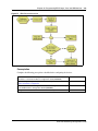
Programming BRI S-loops, lines and ISDN devices . . . . . . . . . . . . . . . . 229
To set BRI properties for ISDN device connections ....................................................230
BRI ISDN: BRI loop properties . . . . . . . . . . . . . . . . . . . . . . . . . . . . . . . . . . 233
CLID: Name display . . . . . . . . . . . . . . . . . . . . . . . . . . . . . . . . . . . . . . . . . . 241
Configuring CLID on your system . . . . . . . . . . . . . . . . . . . . . . . . . . . . . . . 247
To set up alpha tagging on your system......................................................................249
To program the Business Name ..................................................................................250
Dialing plans . . . . . . . . . . . . . . . . . . . . . . . . . . . . . . . . . . . . . . . . . . . . . . . . 253
Dialing plan: Routing configurations . . . . . . . . . . . . . . . . . . . . . . . . . . . . 283
To build a route to allow local calls ..............................................................................285
To set up a route through a dedicated trunk................................................................286
To build a route for a secondary carrier.......................................................................288
To set up the multiple routing overflow feature............................................................289
To program the PRI routing table ................................................................................291
To program a long distance carrier access code into a destination code....................292
Dialing plan: Routing and destination codes . . . . . . . . . . . . . . . . . . . . . . 295
Dialing plan: Line pools and line pool codes . . . . . . . . . . . . . . . . . . . . . . 303
Dialing plan: System settings . . . . . . . . . . . . . . . . . . . . . . . . . . . . . . . . . . 309
Dialing plan: Public network . . . . . . . . . . . . . . . . . . . . . . . . . . . . . . . . . . . 317
Dialing plan: Private network settings . . . . . . . . . . . . . . . . . . . . . . . . . . . 323
Public networking: Setting up basic systems . . . . . . . . . . . . . . . . . . . . . 329
Public networking: Tandem calls from private node . . . . . . . . . . . . . . . . 333
Private networking: MCDN over PRI and VoIP . . . . . . . . . . . . . . . . . . . . . 335
To set up the M1 in a BCM network ............................................................................349
To enable MCDN functionality over PRI fallback lines ................................................349
Private networking: Using shared line pools . . . . . . . . . . . . . . . . . . . . . . 353
Private networking: Basic parameters . . . . . . . . . . . . . . . . . . . . . . . . . . . 355
Private networking: MCDN and ETSI network features . . . . . . . . . . . . . . 359
N0060606
Task List
5
To configure ICCL .......................................................................................................360
To enable TRO ............................................................................................................360
To enable TAT.............................................................................................................360
To enable MCID and network diversion ......................................................................361
Private networking: PRI and VoIP tandem networks . . . . . . . . . . . . . . . . 363
To set up a network of BCMs ......................................................................................368
Private networking: DPNSS network services (UK only) . . . . . . . . . . . . 371
To program IPL............................................................................................................373
To set Loop avoidance during hardware configuration................................................374
Private networking: Using destination codes . . . . . . . . . . . . . . . . . . . . . 379
Private networking: PRI Call-by-Call services . . . . . . . . . . . . . . . . . . . . . 383
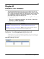
Configuring voice messaging . . . . . . . . . . . . . . . . . . . . . . . . . . . . . . . . . . 387
Configuring centralized voice mail . . . . . . . . . . . . . . . . . . . . . . . . . . . . . . 391
To configure the host system ......................................................................................393
To set up a satellite system for voice mail...................................................................394
To set up a PRI connection on the system ..................................................................396
VoIP overview . . . . . . . . . . . . . . . . . . . . . . . . . . . . . . . . . . . . . . . . . . . . . . . 397
VoIP trunk gateways . . . . . . . . . . . . . . . . . . . . . . . . . . . . . . . . . . . . . . . . . . 401
Configuring VoIP trunk gateways . . . . . . . . . . . . . . . . . . . . . . . . . . . . . . . 415
To configure H323 media parameters .........................................................................416
To configure SIP media parameters ............................................................................416
To configure a remote gateway ...................................................................................419
VoIP interoperability: Gatekeeper configuration . . . . . . . . . . . . . . . . . . . 423
T.38 fax . . . . . . . . . . . . . . . . . . . . . . . . . . . . . . . . . . . . . . . . . . . . . . . . . . . . . 425
To verify codecs in Element Manager .........................................................................425
To enable a T.38 fax....................................................................................................426
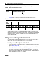
Setting up VoIP trunks for fallback . . . . . . . . . . . . . . . . . . . . . . . . . . . . . . 429
To add the PSTN route (to other system)....................................................................430
To add the PSTN route to the local PSTN lines ..........................................................430
To add the VoIP route .................................................................................................430
To assign PSTN line pool (to other system) ................................................................430
To assign PSTN line pool to local PSTN lines.............................................................430
To assign a VoIP line pool...........................................................................................431
To create destination codes for your fallback route .....................................................431
To configure the VoIP schedule for all fallback destination codes ..............................432
To set up the VoIP schedule for routing services ........................................................433
To activate the VoIP line from the control set ..............................................................433
To deactivate a schedule.............................................................................................434
BCM 4.0 Networking Configuration Guide
6
Task List
Port ranges overview . . . . . . . . . . . . . . . . . . . . . . . . . . . . . . . . . . . . . . . . . 439
Port Ranges Panel . . . . . . . . . . . . . . . . . . . . . . . . . . . . . . . . . . . . . . . . . . . 441
To add new port ranges in the RTP over UDP table ...................................................442
To delete port ranges from the RTP over UDP table...................................................442
To modify an entry on the RTP over UDP table ..........................................................443
To add new port ranges in the UDP table ...................................................................443
To delete port ranges from the UDP table ...................................................................443
To modify an entry on the UDP table ..........................................................................444
Media Gateways . . . . . . . . . . . . . . . . . . . . . . . . . . . . . . . . . . . . . . . . . . . . . 445
Call security and remote access . . . . . . . . . . . . . . . . . . . . . . . . . . . . . . . . 447
Call Security: Configuring Direct Inward System Access (DISA) . . . . . . 457
Call security: Restriction filters . . . . . . . . . . . . . . . . . . . . . . . . . . . . . . . . . 463
To add a restriction filter ..............................................................................................465
Call security: Remote access packages . . . . . . . . . . . . . . . . . . . . . . . . . . 469
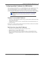
Configuring CoS passwords for remote access . . . . . . . . . . . . . . . . . . . 473
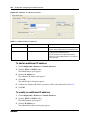
To add or modify a CoS password ..............................................................................475
To access the system over a public network ...............................................................477
To bypass the restriction filters on a telephone ...........................................................477
Data networking overview . . . . . . . . . . . . . . . . . . . . . . . . . . . . . . . . . . . . . 479
Prerequisites checklist . . . . . . . . . . . . . . . . . . . . . . . . . . . . . . . . . . . . . . . . 481
To set the published IP address ..................................................................................485
Configuring the LAN resources . . . . . . . . . . . . . . . . . . . . . . . . . . . . . . . . . 493
To view the available LAN resources ..........................................................................493
To configure a LAN interface .......................................................................................495
To configure the LAN as a DHCP client ......................................................................498
To add an additional IP address..................................................................................499
To modify an additional IP Address.............................................................................500
To delete an additional IP address ..............................................................................501
Configuring the WAN resources . . . . . . . . . . . . . . . . . . . . . . . . . . . . . . . . 503
To view available WAN resources ...............................................................................505
To set WAN T1 parameters .........................................................................................508
To set WAN Sync Parameters.....................................................................................510
To set WAN Frame Relay Parameters ........................................................................511
To add PVC congestion control...................................................................................515
To modify a PVC setting ..............................................................................................516
To delete a PVC congestion control setting ................................................................516
To add an additional IP address..................................................................................522
To modify an additional IP address .............................................................................522
To delete an IP address ..............................................................................................523
To add a DLCI to IP Mapping entry .............................................................................523
N0060606
Task List
7
Data modules . . . . . . . . . . . . . . . . . . . . . . . . . . . . . . . . . . . . . . . . . . . . . . . . 525
To configure the DDI Mux............................................................................................528
To remove a line assignment ......................................................................................530
To view the current settings for the data module.........................................................532
To assign one or more Fixed lines to the data module................................................533
Configuring the Dial-up resources . . . . . . . . . . . . . . . . . . . . . . . . . . . . . . 537
To access the BCM for maintenance over an analog line ...........................................541
To configure the Dial-in parameters ............................................................................541
To change the Modem Region ....................................................................................542
To configure ISDN dial-in parameters .........................................................................542
To create a modem interface.......................................................................................543
To enable or disable the modem interface ..................................................................544
To configure the modem interface ...............................................................................544
To configure the Modem Link Parameters tab ............................................................545
To configure the Modem IP Address Specification tab................................................547
To configure the Modem Access Parameters tab .......................................................548
To create an ISDN dial out interface ...........................................................................550
To configure an ISDN interface ...................................................................................550
To configure the ISDN Link Parameters......................................................................552
To configure the ISDN Access Parameters .................................................................553
To modify the characteristics of an existing ISDN channel .........................................555
To delete an ISDN channel from the ISDN Channel Characteristics table..................555
To delete an ISDN interface ........................................................................................555
To create a PPPoE dial up interface ...........................................................................556
To configure the PPPoE Link Parameters...................................................................558
To configure the PPPoE IP Address Specifications ....................................................559
To configure PPPoE DNS Settings .............................................................................560
To configure PPPoE Access Parameters ....................................................................561
To delete a PPPoE interface .......................................................................................562
To add an auto dial-out interface .................................................................................564
To manually disconnect an auto dial-out interface ......................................................564
Configuring Net Link Manager . . . . . . . . . . . . . . . . . . . . . . . . . . . . . . . . . . 567
To enable or disable Net Link Manager.......................................................................569
Configuring IP Routing . . . . . . . . . . . . . . . . . . . . . . . . . . . . . . . . . . . . . . . . 573
To add a static route to the routing table .....................................................................574
To modify the static route configuration.......................................................................575
To delete a static route ................................................................................................575
To configure global settings for IP Routing..................................................................576
To configure RIP parameters on a network interface ..................................................579
To add OSPF NBMA Neighbors ..................................................................................586
To delete OSPF NBMA Neighbors ..............................................................................586
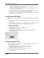
Configuring DHCP . . . . . . . . . . . . . . . . . . . . . . . . . . . . . . . . . . . . . . . . . . . . 589
To set the DHCP Mode ...............................................................................................590
To add an address range ............................................................................................595
To modify an address range ........................................................................................596
To delete an address range.........................................................................................597
To add a reserved address..........................................................................................597
To add a Remote Scope..............................................................................................600
BCM 4.0 Networking Configuration Guide
8
Task List
To modify a remote scope address range ...................................................................602
To delete a remote scope address range ....................................................................603
To add a remote scope reserved address...................................................................603
To delete a remote scope reserved address ...............................................................604
To view the Lease information.....................................................................................604
To add a server to the DHCP Server list .....................................................................606
To delete a server from the DHCP Server List ............................................................607
Configuring NAT (Network Address Translation) . . . . . . . . . . . . . . . . . . 613
To enable or disable NAT ............................................................................................614
To select Default rules.................................................................................................615
To assign a filter to an account....................................................................................620
To modify a filter applied to an account.......................................................................621
To delete a filter applied to an account........................................................................621
Configuring IP Filter Rules . . . . . . . . . . . . . . . . . . . . . . . . . . . . . . . . . . . . . 623
To enable default rules ................................................................................................624
To enable IP filters.......................................................................................................625
To add an inbound filter ...............................................................................................628
To modify an inbound filter ..........................................................................................629
To delete an inbound filter ...........................................................................................629
To add an outbound filter.............................................................................................644
To modify an outbound filter ........................................................................................644
To delete an outbound filter .........................................................................................644
To configure the order of the inbound filters................................................................645
To configure the order of the outbound filters..............................................................645
Virtual Private Networks (VPN) . . . . . . . . . . . . . . . . . . . . . . . . . . . . . . . . . 649
To change the IPSec global settings ...........................................................................662
To add a branch office IPSec tunnel ...........................................................................665
To add a Local Accessible Network to the Branch Office IPSec tunnel ......................668
To add a Remote Accessible Network to the Branch Office IPSec tunnel ..................669
To modify a Branch Office IPSec Tunnel ....................................................................670
To modify a Local Accessible Network to the Branch Office IPSec tunnel..................671
To modify a Remote Accessible Network to the Branch Office IPSec tunnel..............671
To delete a branch office IPSec tunnel........................................................................672
To add a remote user tunnel .......................................................................................678
To modify a remote user tunnel...................................................................................682
To delete a remote user tunnel....................................................................................682
To add a split tunnel network.......................................................................................682
To modify a split tunnel network ..................................................................................683
To delete a split tunnel network...................................................................................683
To add an IP address pool ..........................................................................................684
To modify an IP address pool......................................................................................685
To delete an IP address pool.......................................................................................686
Configuring DNS . . . . . . . . . . . . . . . . . . . . . . . . . . . . . . . . . . . . . . . . . . . . . 687
To configure DNS services settings ............................................................................688
Configuring Web Cache . . . . . . . . . . . . . . . . . . . . . . . . . . . . . . . . . . . . . . . 691
To configure Web Cache settings ...............................................................................692
N0060606
Task List
9
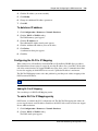
Configuring QoS (Quality of Service) Queuing . . . . . . . . . . . . . . . . . . . . 695
To configure QoS Queuing by Interface ......................................................................695
To modify Queue Settings ...........................................................................................697
To configure QoS queuing by account ........................................................................700
To modify QoS Queuing by Account ...........................................................................700
VLAN overview . . . . . . . . . . . . . . . . . . . . . . . . . . . . . . . . . . . . . . . . . . . . . . 701
Silence suppression . . . . . . . . . . . . . . . . . . . . . . . . . . . . . . . . . . . . . . . . . . 703
ISDN overview . . . . . . . . . . . . . . . . . . . . . . . . . . . . . . . . . . . . . . . . . . . . . . . 709
Codec rates . . . . . . . . . . . . . . . . . . . . . . . . . . . . . . . . . . . . . . . . . . . . . . . . . 721
Stateful Packet Filters . . . . . . . . . . . . . . . . . . . . . . . . . . . . . . . . . . . . . . . . . 723
BCM 4.0 Networking Configuration Guide
10
Task List
N0060606
11
Contents
Chapter 1
Getting started with BCM . . . . . . . . . . . . . . . . . . . . . . . . . . . . . . . . . . . . . . . 29
About this guide . . . . . . . . . . . . . . . . . . . . . . . . . . . . . . . . . . . . . . . . . . . . . . . . . . . . . . 29
Purpose . . . . . . . . . . . . . . . . . . . . . . . . . . . . . . . . . . . . . . . . . . . . . . . . . . . . . . . . . 29
Audience . . . . . . . . . . . . . . . . . . . . . . . . . . . . . . . . . . . . . . . . . . . . . . . . . . . . . . . . 29
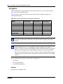
Acronyms . . . . . . . . . . . . . . . . . . . . . . . . . . . . . . . . . . . . . . . . . . . . . . . . . . . . . . . . . . . 30
Organization . . . . . . . . . . . . . . . . . . . . . . . . . . . . . . . . . . . . . . . . . . . . . . . . . . . . . 31
About BCM . . . . . . . . . . . . . . . . . . . . . . . . . . . . . . . . . . . . . . . . . . . . . . . . . . . . . . . . . 31
BCM key hardware elements . . . . . . . . . . . . . . . . . . . . . . . . . . . . . . . . . . . . . . . . 31
Symbols and conventions used in this guide . . . . . . . . . . . . . . . . . . . . . . . . . . . . . . . . 33
Related publications . . . . . . . . . . . . . . . . . . . . . . . . . . . . . . . . . . . . . . . . . . . . . . . . . . 34
How to get Help . . . . . . . . . . . . . . . . . . . . . . . . . . . . . . . . . . . . . . . . . . . . . . . . . . . . . . 39
Getting Help from the Nortel Web site . . . . . . . . . . . . . . . . . . . . . . . . . . . . . . . . . 39
Getting Help over the phone from a Nortel Solutions Center . . . . . . . . . . . . . . . . 39
Getting Help through a Nortel distributor or reseller . . . . . . . . . . . . . . . . . . . . . . . 39
Chapter 2
System telephony networking overview . . . . . . . . . . . . . . . . . . . . . . . . . . . 41
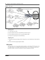
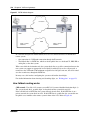
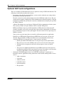
Basic system configurations . . . . . . . . . . . . . . . . . . . . . . . . . . . . . . . . . . . . . . . . . . . . 41
PBX system . . . . . . . . . . . . . . . . . . . . . . . . . . . . . . . . . . . . . . . . . . . . . . . . . . . . . . 41
DID system . . . . . . . . . . . . . . . . . . . . . . . . . . . . . . . . . . . . . . . . . . . . . . . . . . . . . . 42
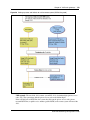
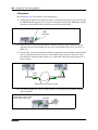
Basic telephony routing . . . . . . . . . . . . . . . . . . . . . . . . . . . . . . . . . . . . . . . . . . . . . 43
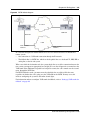
Tandem calling to a remote PSTN . . . . . . . . . . . . . . . . . . . . . . . . . . . . . . . . . . . . 44
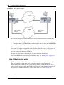
Private network parameters . . . . . . . . . . . . . . . . . . . . . . . . . . . . . . . . . . . . . . . . . . . . . 45
Lines used for networking . . . . . . . . . . . . . . . . . . . . . . . . . . . . . . . . . . . . . . . . . . . 46
Types of private networks . . . . . . . . . . . . . . . . . . . . . . . . . . . . . . . . . . . . . . . . . . . 47
Routing-based networks using T1 E&M lines . . . . . . . . . . . . . . . . . . . . . . . . . . . . 47
PRI networking using Call-by-Call services . . . . . . . . . . . . . . . . . . . . . . . . . . . . . 49
PRI SL-1/Q.Sig/DPNSS and VoIP trunk networking . . . . . . . . . . . . . . . . . . . . . . . 49
System dialing plans . . . . . . . . . . . . . . . . . . . . . . . . . . . . . . . . . . . . . . . . . . . . . . . 50
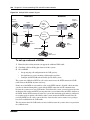
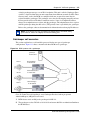
Creating tandem private networks . . . . . . . . . . . . . . . . . . . . . . . . . . . . . . . . . . . . 50
Understanding MCDN network features . . . . . . . . . . . . . . . . . . . . . . . . . . . . . . . . . . . 53
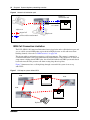
Network Call Redirection Information . . . . . . . . . . . . . . . . . . . . . . . . . . . . . . . . . . 53
ISDN Call Connection Limitation . . . . . . . . . . . . . . . . . . . . . . . . . . . . . . . . . . . . . . 54
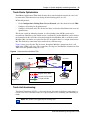
Trunk Route Optimization . . . . . . . . . . . . . . . . . . . . . . . . . . . . . . . . . . . . . . . . . . . 55
Trunk Anti-tromboning . . . . . . . . . . . . . . . . . . . . . . . . . . . . . . . . . . . . . . . . . . . . . . 55
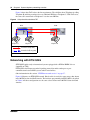
Networking with ETSI QSIG . . . . . . . . . . . . . . . . . . . . . . . . . . . . . . . . . . . . . . . . . . . . 56
ETSI Euro network services . . . . . . . . . . . . . . . . . . . . . . . . . . . . . . . . . . . . . . . . . 57
BCM 4.0 Networking Configuration Guide
12
Contents
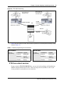
DPNSS 1 services . . . . . . . . . . . . . . . . . . . . . . . . . . . . . . . . . . . . . . . . . . . . . . . . . 58
DPNSS 1 capabilities . . . . . . . . . . . . . . . . . . . . . . . . . . . . . . . . . . . . . . . . . . . . . . 58
DPNSS 1 features . . . . . . . . . . . . . . . . . . . . . . . . . . . . . . . . . . . . . . . . . . . . . . . . . 59
Private networking with DPNSS . . . . . . . . . . . . . . . . . . . . . . . . . . . . . . . . . . . . . . . . . 65
Chapter 3
Telephony programming: Configuring call traffic . . . . . . . . . . . . . . . . . . . 67
Incoming calls . . . . . . . . . . . . . . . . . . . . . . . . . . . . . . . . . . . . . . . . . . . . . . . . . . . . . . . 70
Outgoing calls . . . . . . . . . . . . . . . . . . . . . . . . . . . . . . . . . . . . . . . . . . . . . . . . . . . . . . . 74
Chapter 4
Application resources panel . . . . . . . . . . . . . . . . . . . . . . . . . . . . . . . . . . . . . 77
Chapter 5
Configuring application resources. . . . . . . . . . . . . . . . . . . . . . . . . . . . . . . . 83
Types of resources . . . . . . . . . . . . . . . . . . . . . . . . . . . . . . . . . . . . . . . . . . . . . . . . . . . 83
Rules for managing the resources . . . . . . . . . . . . . . . . . . . . . . . . . . . . . . . . . . . . . . . . 85
Signaling channel rules . . . . . . . . . . . . . . . . . . . . . . . . . . . . . . . . . . . . . . . . . . . . . 85
Media channel rules . . . . . . . . . . . . . . . . . . . . . . . . . . . . . . . . . . . . . . . . . . . . . . . 85
DSP resources rules . . . . . . . . . . . . . . . . . . . . . . . . . . . . . . . . . . . . . . . . . . . . . . . 86
Voice bus path . . . . . . . . . . . . . . . . . . . . . . . . . . . . . . . . . . . . . . . . . . . . . . . . . . . 87
Media gateways . . . . . . . . . . . . . . . . . . . . . . . . . . . . . . . . . . . . . . . . . . . . . . . . . . 87
Determining the resources you require . . . . . . . . . . . . . . . . . . . . . . . . . . . . . . . . . . . . 88
IVR and IVR Fax . . . . . . . . . . . . . . . . . . . . . . . . . . . . . . . . . . . . . . . . . . . . . . . . . . 89
IP telephones . . . . . . . . . . . . . . . . . . . . . . . . . . . . . . . . . . . . . . . . . . . . . . . . . . . . 90
IP Trunks . . . . . . . . . . . . . . . . . . . . . . . . . . . . . . . . . . . . . . . . . . . . . . . . . . . . . . . . 90
Record of required resources . . . . . . . . . . . . . . . . . . . . . . . . . . . . . . . . . . . . . . . . 93
Evaluation . . . . . . . . . . . . . . . . . . . . . . . . . . . . . . . . . . . . . . . . . . . . . . . . . . . . . . . 94
Understanding the minimum and maximum values . . . . . . . . . . . . . . . . . . . . . . . 96
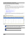
Application Resource Reservations . . . . . . . . . . . . . . . . . . . . . . . . . . . . . . . . . . . 97
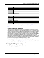
Changing the DS30 split . . . . . . . . . . . . . . . . . . . . . . . . . . . . . . . . . . . . . . . . . . . . . . . 98
Chapter 6
Configuring resources — media bay modules . . . . . . . . . . . . . . . . . . . . . 101
Explaining the Media Bay Modules headings . . . . . . . . . . . . . . . . . . . . . . . . . . . . . . 102
Media bay module Bus numbers . . . . . . . . . . . . . . . . . . . . . . . . . . . . . . . . . . . . . 103
Identifying the module . . . . . . . . . . . . . . . . . . . . . . . . . . . . . . . . . . . . . . . . . . . . . 103
Module types and capacities . . . . . . . . . . . . . . . . . . . . . . . . . . . . . . . . . . . . . . . . 106
Ports on Bus . . . . . . . . . . . . . . . . . . . . . . . . . . . . . . . . . . . . . . . . . . . . . . . . . . . . 108
Defining trunk module types and settings . . . . . . . . . . . . . . . . . . . . . . . . . . . . . . . . . 108
Configuring the trunk module to line type . . . . . . . . . . . . . . . . . . . . . . . . . . . . . . 109
Determining clock sources for DTMs or BRIs . . . . . . . . . . . . . . . . . . . . . . . . . . . 110
Timing within networks . . . . . . . . . . . . . . . . . . . . . . . . . . . . . . . . . . . . . . . . . . . . 111
N0060606
Contents
13
T1 interface parameters (region-specific) . . . . . . . . . . . . . . . . . . . . . . . . . . . . . . 111
E1 parameters (region-specific) . . . . . . . . . . . . . . . . . . . . . . . . . . . . . . . . . . . . . 113
PRI Call-by-Call service selection . . . . . . . . . . . . . . . . . . . . . . . . . . . . . . . . . . . . 114
Provisioning lines (PRI, T1, DASS2) . . . . . . . . . . . . . . . . . . . . . . . . . . . . . . . . . . 116
Provisioning a line . . . . . . . . . . . . . . . . . . . . . . . . . . . . . . . . . . . . . . . . . . . . . . . . 116
Provisioning BRI loops/lines . . . . . . . . . . . . . . . . . . . . . . . . . . . . . . . . . . . . . . . . 117
Deprovisioning a line/loop . . . . . . . . . . . . . . . . . . . . . . . . . . . . . . . . . . . . . . . . . . 117
Internally-driven channels . . . . . . . . . . . . . . . . . . . . . . . . . . . . . . . . . . . . . . . . . . . . . 117
Working with the modules . . . . . . . . . . . . . . . . . . . . . . . . . . . . . . . . . . . . . . . . . . . . . 118
Chapter 7
Managing modules. . . . . . . . . . . . . . . . . . . . . . . . . . . . . . . . . . . . . . . . . . . . 119
Disabling or enabling a bus or module . . . . . . . . . . . . . . . . . . . . . . . . . . . . . . . . . . . 119
Disabling or enabling a port channel setting . . . . . . . . . . . . . . . . . . . . . . . . . . . . . . . 119
Chapter 8
Configuring telephony resources. . . . . . . . . . . . . . . . . . . . . . . . . . . . . . . . 121
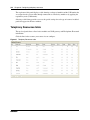
Telephony Resources table . . . . . . . . . . . . . . . . . . . . . . . . . . . . . . . . . . . . . . . . . . . . 122
Media bay module panels . . . . . . . . . . . . . . . . . . . . . . . . . . . . . . . . . . . . . . . . . . . . . 124
Trunk Module Parameters . . . . . . . . . . . . . . . . . . . . . . . . . . . . . . . . . . . . . . . . . . 124
Call-by-Call Service Selection . . . . . . . . . . . . . . . . . . . . . . . . . . . . . . . . . . . . . . . 128
Port details . . . . . . . . . . . . . . . . . . . . . . . . . . . . . . . . . . . . . . . . . . . . . . . . . . . . . 130
Provisioning module lines/loops . . . . . . . . . . . . . . . . . . . . . . . . . . . . . . . . . . . . . . . . 132
IP telephones . . . . . . . . . . . . . . . . . . . . . . . . . . . . . . . . . . . . . . . . . . . . . . . . . . . . . . . 133
IP Terminal Global Settings . . . . . . . . . . . . . . . . . . . . . . . . . . . . . . . . . . . . . . . . 133
IP telephone set details . . . . . . . . . . . . . . . . . . . . . . . . . . . . . . . . . . . . . . . . . . . . 135
Voice over IP trunks . . . . . . . . . . . . . . . . . . . . . . . . . . . . . . . . . . . . . . . . . . . . . . . . . 136
Routing table . . . . . . . . . . . . . . . . . . . . . . . . . . . . . . . . . . . . . . . . . . . . . . . . . . . . 136
IP Trunk Settings . . . . . . . . . . . . . . . . . . . . . . . . . . . . . . . . . . . . . . . . . . . . . . . . . 138
H323 Settings . . . . . . . . . . . . . . . . . . . . . . . . . . . . . . . . . . . . . . . . . . . . . . . . . . . 140
H323 Media Parameters . . . . . . . . . . . . . . . . . . . . . . . . . . . . . . . . . . . . . . . . . . . 143
SIP Settings . . . . . . . . . . . . . . . . . . . . . . . . . . . . . . . . . . . . . . . . . . . . . . . . . . . . 145
SIP Media Parameters . . . . . . . . . . . . . . . . . . . . . . . . . . . . . . . . . . . . . . . . . . . . 147
SIP URI Map . . . . . . . . . . . . . . . . . . . . . . . . . . . . . . . . . . . . . . . . . . . . . . . . . . . . 149
Chapter 9
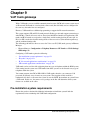
VoIP trunk gateways . . . . . . . . . . . . . . . . . . . . . . . . . . . . . . . . . . . . . . . . . . 151
Pre-installation system requirements . . . . . . . . . . . . . . . . . . . . . . . . . . . . . . . . . . . . 151
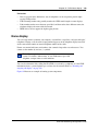
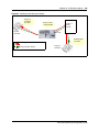
How VoIP trunks make a network . . . . . . . . . . . . . . . . . . . . . . . . . . . . . . . . . . . . . . . 152
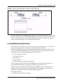
Local gateway programming . . . . . . . . . . . . . . . . . . . . . . . . . . . . . . . . . . . . . . . . . . . 153
Routing Table . . . . . . . . . . . . . . . . . . . . . . . . . . . . . . . . . . . . . . . . . . . . . . . . . . . . . . 154
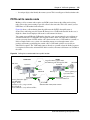
PSTN call to remote node . . . . . . . . . . . . . . . . . . . . . . . . . . . . . . . . . . . . . . . . . . . . . 155
Fallback to PSTN from VoIP trunks . . . . . . . . . . . . . . . . . . . . . . . . . . . . . . . . . . . . . . 157
BCM 4.0 Networking Configuration Guide
14
Contents
Describing a fallback network . . . . . . . . . . . . . . . . . . . . . . . . . . . . . . . . . . . . . . . 157
How fallback routing works . . . . . . . . . . . . . . . . . . . . . . . . . . . . . . . . . . . . . . . . . 158
Optional VoIP trunk configurations . . . . . . . . . . . . . . . . . . . . . . . . . . . . . . . . . . . . . . 160
Gatekeeper call scenarios . . . . . . . . . . . . . . . . . . . . . . . . . . . . . . . . . . . . . . . . . . 161
Operational notes and restrictions . . . . . . . . . . . . . . . . . . . . . . . . . . . . . . . . . . . 162
Chapter 10
Configuring lines . . . . . . . . . . . . . . . . . . . . . . . . . . . . . . . . . . . . . . . . . . . . . 165
Trunk/Line data - main panel . . . . . . . . . . . . . . . . . . . . . . . . . . . . . . . . . . . . . . . . . . . 166
Parameters . . . . . . . . . . . . . . . . . . . . . . . . . . . . . . . . . . . . . . . . . . . . . . . . . . . . . . . . 168
Properties . . . . . . . . . . . . . . . . . . . . . . . . . . . . . . . . . . . . . . . . . . . . . . . . . . . . . . . . . 169
Preferences (lines) . . . . . . . . . . . . . . . . . . . . . . . . . . . . . . . . . . . . . . . . . . . . . . . . . . 171
Restrictions (Line and Remote) . . . . . . . . . . . . . . . . . . . . . . . . . . . . . . . . . . . . . . . . . 174
Assigned DNs . . . . . . . . . . . . . . . . . . . . . . . . . . . . . . . . . . . . . . . . . . . . . . . . . . . . . . 175
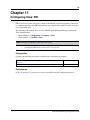
Chapter 11
Configuring lines: PRI . . . . . . . . . . . . . . . . . . . . . . . . . . . . . . . . . . . . . . . . . 177
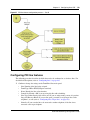
Configuring PRI line features . . . . . . . . . . . . . . . . . . . . . . . . . . . . . . . . . . . . . . . . . . . 179
Configuring PRI Call-by-Call services . . . . . . . . . . . . . . . . . . . . . . . . . . . . . . . . . . . . 180
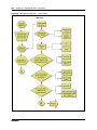
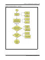
Chapter 12
Configuring lines: Target lines . . . . . . . . . . . . . . . . . . . . . . . . . . . . . . . . . . 183
Configuring Target line settings . . . . . . . . . . . . . . . . . . . . . . . . . . . . . . . . . . . . . . . . . 186
Chapter 13
Configuring lines: T1-E&M . . . . . . . . . . . . . . . . . . . . . . . . . . . . . . . . . . . . . 187
Configuring E&M line features . . . . . . . . . . . . . . . . . . . . . . . . . . . . . . . . . . . . . . . . . . 191
Chapter 14
Configuring lines: T1-Loop start . . . . . . . . . . . . . . . . . . . . . . . . . . . . . . . . 193
Configuring digital (T1/E1) loop start lines . . . . . . . . . . . . . . . . . . . . . . . . . . . . . . . . . 197
Chapter 15
Configuring lines: T1-Digital Ground Start . . . . . . . . . . . . . . . . . . . . . . . . 199
Configuring digital ground start line features . . . . . . . . . . . . . . . . . . . . . . . . . . . . . . . 202
Chapter 16
Configuring lines: T1-DID . . . . . . . . . . . . . . . . . . . . . . . . . . . . . . . . . . . . . . 205
Configuring DID line features . . . . . . . . . . . . . . . . . . . . . . . . . . . . . . . . . . . . . . . . . . 208
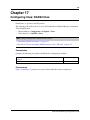
Chapter 17
Configuring lines: DASS2 lines . . . . . . . . . . . . . . . . . . . . . . . . . . . . . . . . . 211
Configuring DASS2 line features . . . . . . . . . . . . . . . . . . . . . . . . . . . . . . . . . . . . . . . . 213
N0060606
Contents
15
Chapter 18
Configuring lines: DPNSS lines . . . . . . . . . . . . . . . . . . . . . . . . . . . . . . . . . 217
Configuring DPNSS line features . . . . . . . . . . . . . . . . . . . . . . . . . . . . . . . . . . . . . . . 219
Chapter 19
BRI ISDN: BRI T-loops . . . . . . . . . . . . . . . . . . . . . . . . . . . . . . . . . . . . . . . . . 223
Configuring BRI T-loop parameters . . . . . . . . . . . . . . . . . . . . . . . . . . . . . . . . . . . . . . 225
Configuring BRI lines . . . . . . . . . . . . . . . . . . . . . . . . . . . . . . . . . . . . . . . . . . . . . . . . . 225
Chapter 20
Programming BRI S-loops, lines and ISDN devices . . . . . . . . . . . . . . . . . 229
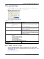
Setting BRI properties for ISDN device connections . . . . . . . . . . . . . . . . . . . . . . . . . 229
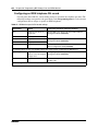
DN records: ISDN devices . . . . . . . . . . . . . . . . . . . . . . . . . . . . . . . . . . . . . . . . . . . . . 230
Configuring an ISDN telephone DN record . . . . . . . . . . . . . . . . . . . . . . . . . . . . . 232
Chapter 21
BRI ISDN: BRI loop properties . . . . . . . . . . . . . . . . . . . . . . . . . . . . . . . . . . 233
Configure loop type and general parameters . . . . . . . . . . . . . . . . . . . . . . . . . . . . . . 233
T-loop general settings . . . . . . . . . . . . . . . . . . . . . . . . . . . . . . . . . . . . . . . . . . . . . . . 235
T-loop SPIDS and network DNs . . . . . . . . . . . . . . . . . . . . . . . . . . . . . . . . . . . . . . . . 235
T-loops D-packet service . . . . . . . . . . . . . . . . . . . . . . . . . . . . . . . . . . . . . . . . . . . . . . 237
S-loops assigned DNs . . . . . . . . . . . . . . . . . . . . . . . . . . . . . . . . . . . . . . . . . . . . . . . . 238
Chapter 22
CLID: Name display . . . . . . . . . . . . . . . . . . . . . . . . . . . . . . . . . . . . . . . . . . . 241
Business name display . . . . . . . . . . . . . . . . . . . . . . . . . . . . . . . . . . . . . . . . . . . . 242
Alpha tagging for name display . . . . . . . . . . . . . . . . . . . . . . . . . . . . . . . . . . . . . . 242
Name display . . . . . . . . . . . . . . . . . . . . . . . . . . . . . . . . . . . . . . . . . . . . . . . . . . . . . . . 243
Incoming and outgoing call display . . . . . . . . . . . . . . . . . . . . . . . . . . . . . . . . . . . . . . 244
Chapter 23
Configuring CLID on your system . . . . . . . . . . . . . . . . . . . . . . . . . . . . . . . 247
Programming incoming CLID . . . . . . . . . . . . . . . . . . . . . . . . . . . . . . . . . . . . . . . . . . 249
Using alpha tagging for name display (incoming) . . . . . . . . . . . . . . . . . . . . . . . . 249
Programming outgoing CLID . . . . . . . . . . . . . . . . . . . . . . . . . . . . . . . . . . . . . . . . . . . 250
Chapter 24
Dialing plans. . . . . . . . . . . . . . . . . . . . . . . . . . . . . . . . . . . . . . . . . . . . . . . . . 253
Creating dialing plans . . . . . . . . . . . . . . . . . . . . . . . . . . . . . . . . . . . . . . . . . . . . . . . . 253
Public and Private Received numbers . . . . . . . . . . . . . . . . . . . . . . . . . . . . . . . . . . . . 256
Private network dialing . . . . . . . . . . . . . . . . . . . . . . . . . . . . . . . . . . . . . . . . . . . . . . . 257
Setting up public network dialing . . . . . . . . . . . . . . . . . . . . . . . . . . . . . . . . . . . . . . . . 257
Outgoing call routing . . . . . . . . . . . . . . . . . . . . . . . . . . . . . . . . . . . . . . . . . . . . . . . . . 258
BCM 4.0 Networking Configuration Guide
16
Contents
Incoming call routing . . . . . . . . . . . . . . . . . . . . . . . . . . . . . . . . . . . . . . . . . . . . . . . . . 260
Processing incoming calls . . . . . . . . . . . . . . . . . . . . . . . . . . . . . . . . . . . . . . . . . . . . . 261
Determining line access dialing . . . . . . . . . . . . . . . . . . . . . . . . . . . . . . . . . . . . . . . . . 264
Understanding access codes . . . . . . . . . . . . . . . . . . . . . . . . . . . . . . . . . . . . . . . . . . 265
Call Park codes . . . . . . . . . . . . . . . . . . . . . . . . . . . . . . . . . . . . . . . . . . . . . . . . . . 266
Creating Direct Dial sets . . . . . . . . . . . . . . . . . . . . . . . . . . . . . . . . . . . . . . . . . . . 267
Tips about access codes . . . . . . . . . . . . . . . . . . . . . . . . . . . . . . . . . . . . . . . . . . . 268
Using the MCDN access codes (tandem calls) . . . . . . . . . . . . . . . . . . . . . . . . . . 268
Line pool access codes . . . . . . . . . . . . . . . . . . . . . . . . . . . . . . . . . . . . . . . . . . . . . . . 269
Using Carrier codes . . . . . . . . . . . . . . . . . . . . . . . . . . . . . . . . . . . . . . . . . . . . . . . . . . 270
Configuring call routing . . . . . . . . . . . . . . . . . . . . . . . . . . . . . . . . . . . . . . . . . . . . . . . 270
Configuring Call-by-Call services . . . . . . . . . . . . . . . . . . . . . . . . . . . . . . . . . . . . . . . 271
Call-by-Call services . . . . . . . . . . . . . . . . . . . . . . . . . . . . . . . . . . . . . . . . . . . . . . 272
Switches supporting Call by Call limits . . . . . . . . . . . . . . . . . . . . . . . . . . . . . . . . 272
Provisioning for Call by Call limits with PRI . . . . . . . . . . . . . . . . . . . . . . . . . . . . . 274
Call by Call service routing . . . . . . . . . . . . . . . . . . . . . . . . . . . . . . . . . . . . . . . . . 274
PRI routing protocols . . . . . . . . . . . . . . . . . . . . . . . . . . . . . . . . . . . . . . . . . . . . . . 275
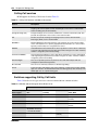
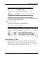
Using destination codes . . . . . . . . . . . . . . . . . . . . . . . . . . . . . . . . . . . . . . . . . . . . . . 275
Why use destination codes? . . . . . . . . . . . . . . . . . . . . . . . . . . . . . . . . . . . . . . . . 276
Deciding on a code . . . . . . . . . . . . . . . . . . . . . . . . . . . . . . . . . . . . . . . . . . . . . . . 277
Adding Carrier access codes to destination codes . . . . . . . . . . . . . . . . . . . . . . . 278
Routing schedules and alternate routes . . . . . . . . . . . . . . . . . . . . . . . . . . . . . . . 279
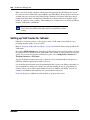
Setting up VoIP trunks for fallback . . . . . . . . . . . . . . . . . . . . . . . . . . . . . . . . . . . . . . 280
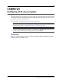
Chapter 25
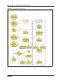
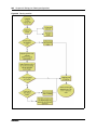
Dialing plan: Routing configurations . . . . . . . . . . . . . . . . . . . . . . . . . . . . . 283
Destination code numbering in a network . . . . . . . . . . . . . . . . . . . . . . . . . . . . . . . . . 285
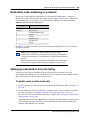
Setting up a destination for local calling . . . . . . . . . . . . . . . . . . . . . . . . . . . . . . . . . . 285
Setting up a route through a dedicated trunk . . . . . . . . . . . . . . . . . . . . . . . . . . . . . . 286
Grouping destination codes using a wild card . . . . . . . . . . . . . . . . . . . . . . . . . . . . . . 287
Programming for least-cost routing . . . . . . . . . . . . . . . . . . . . . . . . . . . . . . . . . . . . . . 288
Using multiple routes and overflow routing . . . . . . . . . . . . . . . . . . . . . . . . . . . . . . . . 288
Dialing plan using public lines . . . . . . . . . . . . . . . . . . . . . . . . . . . . . . . . . . . . . . . 290
Programming the PRI routing table . . . . . . . . . . . . . . . . . . . . . . . . . . . . . . . . . . . . . . 291
Adding Carrier access codes to destination codes . . . . . . . . . . . . . . . . . . . . . . . . . . 292
Using the MCDN access codes to tandem calls . . . . . . . . . . . . . . . . . . . . . . . . . . . . 293
Chapter 26
Dialing plan: Routing and destination codes . . . . . . . . . . . . . . . . . . . . . . 295
Routes . . . . . . . . . . . . . . . . . . . . . . . . . . . . . . . . . . . . . . . . . . . . . . . . . . . . . . . . . . . . 296
Destination codes . . . . . . . . . . . . . . . . . . . . . . . . . . . . . . . . . . . . . . . . . . . . . . . . . . . 298
Alternate routes for routing schedules . . . . . . . . . . . . . . . . . . . . . . . . . . . . . . . . . . . . 300
N0060606
Contents
17
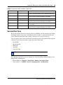
Second Dial Tone . . . . . . . . . . . . . . . . . . . . . . . . . . . . . . . . . . . . . . . . . . . . . . . . . . . 301
Chapter 27
Dialing plan: Line pools and line pool codes . . . . . . . . . . . . . . . . . . . . . . 303
Line pools (and access codes) . . . . . . . . . . . . . . . . . . . . . . . . . . . . . . . . . . . . . . . . . 303
Line pools: DNs tab . . . . . . . . . . . . . . . . . . . . . . . . . . . . . . . . . . . . . . . . . . . . . . . . . . 305
Line pools: Call-by-Call Limits tab (PRI only) . . . . . . . . . . . . . . . . . . . . . . . . . . . . . . 306
Chapter 28
Dialing plan: System settings . . . . . . . . . . . . . . . . . . . . . . . . . . . . . . . . . . . 309
Common dialing plan settings . . . . . . . . . . . . . . . . . . . . . . . . . . . . . . . . . . . . . . . . . . 309
DN length constraints . . . . . . . . . . . . . . . . . . . . . . . . . . . . . . . . . . . . . . . . . . . . . 312
Received number notes . . . . . . . . . . . . . . . . . . . . . . . . . . . . . . . . . . . . . . . . . . . 313
Tips about access codes . . . . . . . . . . . . . . . . . . . . . . . . . . . . . . . . . . . . . . . . . . . 314
Call Park codes . . . . . . . . . . . . . . . . . . . . . . . . . . . . . . . . . . . . . . . . . . . . . . . . . . 315
Chapter 29
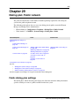
Dialing plan: Public network . . . . . . . . . . . . . . . . . . . . . . . . . . . . . . . . . . . . 317
Public dialing plan settings . . . . . . . . . . . . . . . . . . . . . . . . . . . . . . . . . . . . . . . . . . . . 317
Public Network Settings . . . . . . . . . . . . . . . . . . . . . . . . . . . . . . . . . . . . . . . . . . . 318
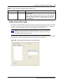
Public network DN lengths . . . . . . . . . . . . . . . . . . . . . . . . . . . . . . . . . . . . . . . . . 319
Carrier Codes . . . . . . . . . . . . . . . . . . . . . . . . . . . . . . . . . . . . . . . . . . . . . . . . . . . 321
Chapter 30
Dialing plan: Private network settings . . . . . . . . . . . . . . . . . . . . . . . . . . . . 323
Private Network dialing plan settings . . . . . . . . . . . . . . . . . . . . . . . . . . . . . . . . . . . . . 323
Private Network Settings . . . . . . . . . . . . . . . . . . . . . . . . . . . . . . . . . . . . . . . . . . . 324
Private Network - MCDN network (PRI SL-1, PRI ETSI, VoIP) . . . . . . . . . . . . . 325
VoIP-specific private network dialing . . . . . . . . . . . . . . . . . . . . . . . . . . . . . . . . . 326
ETSI-specific network features . . . . . . . . . . . . . . . . . . . . . . . . . . . . . . . . . . . . . . 327
Outgoing private calls routing . . . . . . . . . . . . . . . . . . . . . . . . . . . . . . . . . . . . . . . . . . 328
Chapter 31
Public networking: Setting up basic systems. . . . . . . . . . . . . . . . . . . . . . 329
Public networks: PBX system setup . . . . . . . . . . . . . . . . . . . . . . . . . . . . . . . . . . . . . 329
Public network: DID system . . . . . . . . . . . . . . . . . . . . . . . . . . . . . . . . . . . . . . . . . . . . 330
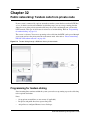
Chapter 32
Public networking: Tandem calls from private node . . . . . . . . . . . . . . . . 333
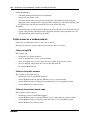
Programming for tandem dialing . . . . . . . . . . . . . . . . . . . . . . . . . . . . . . . . . . . . . . . . 333
Caller access on a tandem network . . . . . . . . . . . . . . . . . . . . . . . . . . . . . . . . . . 334
BCM 4.0 Networking Configuration Guide
18
Contents
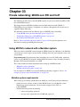
Chapter 33
Private networking: MCDN over PRI and VoIP . . . . . . . . . . . . . . . . . . . . . 335
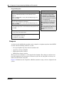
Using MCDN to network with a Meridian system . . . . . . . . . . . . . . . . . . . . . . . . . . . 335
Meridian system requirements . . . . . . . . . . . . . . . . . . . . . . . . . . . . . . . . . . . . . . 335
Meridian MCDN call features over PRI SL-1 lines . . . . . . . . . . . . . . . . . . . . . . . . . . . 337
MCDN networking checklist . . . . . . . . . . . . . . . . . . . . . . . . . . . . . . . . . . . . . . . . 340
UDP-specific programming . . . . . . . . . . . . . . . . . . . . . . . . . . . . . . . . . . . . . . . . . 342
CDP-specific programming . . . . . . . . . . . . . . . . . . . . . . . . . . . . . . . . . . . . . . . . . 342
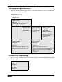
VM programming with Meridian 1 . . . . . . . . . . . . . . . . . . . . . . . . . . . . . . . . . . . . 344
Meridian TRO programming . . . . . . . . . . . . . . . . . . . . . . . . . . . . . . . . . . . . . . . . 344
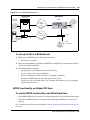
An example of a private network with Meridian 1 . . . . . . . . . . . . . . . . . . . . . . . . 345
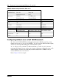
Configuring fallback over a VoIP MCDN network . . . . . . . . . . . . . . . . . . . . . . . . . . . 348
MCDN functionality on fallback PRI lines . . . . . . . . . . . . . . . . . . . . . . . . . . . . . . 349
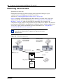
Networking with ETSI QSIG . . . . . . . . . . . . . . . . . . . . . . . . . . . . . . . . . . . . . . . . . . . 350
Chapter 34
Private networking: Using shared line pools . . . . . . . . . . . . . . . . . . . . . . 353
Chapter 35
Private networking: Basic parameters. . . . . . . . . . . . . . . . . . . . . . . . . . . . 355
Private networking protocols . . . . . . . . . . . . . . . . . . . . . . . . . . . . . . . . . . . . . . . . . . . 355
Keycode requirements . . . . . . . . . . . . . . . . . . . . . . . . . . . . . . . . . . . . . . . . . . . . . . . . 355
Remote access to the network . . . . . . . . . . . . . . . . . . . . . . . . . . . . . . . . . . . . . . . . . 356
Other programming that affects private networking . . . . . . . . . . . . . . . . . . . . . . . . . . 356
Types of private networks . . . . . . . . . . . . . . . . . . . . . . . . . . . . . . . . . . . . . . . . . . . . . 356
Chapter 36
Private networking: MCDN and ETSI network features . . . . . . . . . . . . . . 359
Configuring MCDN network features . . . . . . . . . . . . . . . . . . . . . . . . . . . . . . . . . . . . . 359
Configuring ETSI Euro network services . . . . . . . . . . . . . . . . . . . . . . . . . . . . . . . . . . 361
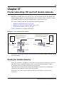
Chapter 37
Private networking: PRI and VoIP tandem networks . . . . . . . . . . . . . . . . 363
Routing for tandem networks . . . . . . . . . . . . . . . . . . . . . . . . . . . . . . . . . . . . . . . . . . . 363
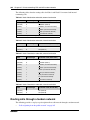
Routing calls through a tandem network . . . . . . . . . . . . . . . . . . . . . . . . . . . . . . . . . . 364
Calls originating from the public network . . . . . . . . . . . . . . . . . . . . . . . . . . . . . . 365
Calls originating in the private network . . . . . . . . . . . . . . . . . . . . . . . . . . . . . . . . 366
Using VoIP to tandem systems . . . . . . . . . . . . . . . . . . . . . . . . . . . . . . . . . . . . . . . . . 367
Chapter 38
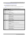
Private networking: DPNSS network services (UK only) . . . . . . . . . . . . . 371
Using the diversion feature . . . . . . . . . . . . . . . . . . . . . . . . . . . . . . . . . . . . . . . . . . . . 371
Using the Redirection feature . . . . . . . . . . . . . . . . . . . . . . . . . . . . . . . . . . . . . . . . . . 372
N0060606
Contents
19
Executive intrusion, Intrusion protection level . . . . . . . . . . . . . . . . . . . . . . . . . . . . . . 373
Call offer . . . . . . . . . . . . . . . . . . . . . . . . . . . . . . . . . . . . . . . . . . . . . . . . . . . . . . . . . . 373
Route optimization . . . . . . . . . . . . . . . . . . . . . . . . . . . . . . . . . . . . . . . . . . . . . . . . . . . 374
Loop avoidance . . . . . . . . . . . . . . . . . . . . . . . . . . . . . . . . . . . . . . . . . . . . . . . . . . . . . 374
Private networking with DPNSS . . . . . . . . . . . . . . . . . . . . . . . . . . . . . . . . . . . . . . . . 374
Guidelines for creating a private dialing plan with DPNSS . . . . . . . . . . . . . . . . . 377
Customizing the DPNSS routing service . . . . . . . . . . . . . . . . . . . . . . . . . . . . . . . 377
Chapter 39
Private networking: Using destination codes . . . . . . . . . . . . . . . . . . . . . . 379
Chapter 40
Private networking: PRI Call-by-Call services. . . . . . . . . . . . . . . . . . . . . . 383
Chapter 41
Configuring voice messaging. . . . . . . . . . . . . . . . . . . . . . . . . . . . . . . . . . . 387
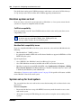
Centralized Voice Messaging (external voice mail) . . . . . . . . . . . . . . . . . . . . . . . . . . 387
Programming MWI and MWC strings . . . . . . . . . . . . . . . . . . . . . . . . . . . . . . . . . 388
Local voice messaging access (CallPilot Manager) . . . . . . . . . . . . . . . . . . . . . . . . . 389
Chapter 42
Configuring centralized voice mail. . . . . . . . . . . . . . . . . . . . . . . . . . . . . . . 391
Local system as host . . . . . . . . . . . . . . . . . . . . . . . . . . . . . . . . . . . . . . . . . . . . . . . . . 391
Meridian system as host . . . . . . . . . . . . . . . . . . . . . . . . . . . . . . . . . . . . . . . . . . . . . . 392
System set up for host system . . . . . . . . . . . . . . . . . . . . . . . . . . . . . . . . . . . . . . . . . 392
System set up for satellite systems . . . . . . . . . . . . . . . . . . . . . . . . . . . . . . . . . . . . . . 393
Configuring the system for centralized voice mail . . . . . . . . . . . . . . . . . . . . . . . . . . . 395
Chapter 43
VoIP overview. . . . . . . . . . . . . . . . . . . . . . . . . . . . . . . . . . . . . . . . . . . . . . . . 397
Creating an IP telephony network . . . . . . . . . . . . . . . . . . . . . . . . . . . . . . . . . . . . . . . 397
Telephones . . . . . . . . . . . . . . . . . . . . . . . . . . . . . . . . . . . . . . . . . . . . . . . . . . . . . 398
Gatekeepers . . . . . . . . . . . . . . . . . . . . . . . . . . . . . . . . . . . . . . . . . . . . . . . . . . . . 398
SIP Proxy . . . . . . . . . . . . . . . . . . . . . . . . . . . . . . . . . . . . . . . . . . . . . . . . . . . . . . 398
IP Network . . . . . . . . . . . . . . . . . . . . . . . . . . . . . . . . . . . . . . . . . . . . . . . . . . . . . . 398
Key VoIP concepts . . . . . . . . . . . . . . . . . . . . . . . . . . . . . . . . . . . . . . . . . . . . . . . . . . 399
Chapter 44
VoIP trunk gateways . . . . . . . . . . . . . . . . . . . . . . . . . . . . . . . . . . . . . . . . . . 401
Pre-installation system requirements . . . . . . . . . . . . . . . . . . . . . . . . . . . . . . . . . . . . 401
How VoIP trunks make a network . . . . . . . . . . . . . . . . . . . . . . . . . . . . . . . . . . . . . . . 402
Local gateway programming . . . . . . . . . . . . . . . . . . . . . . . . . . . . . . . . . . . . . . . . . . . 403
Routing Table . . . . . . . . . . . . . . . . . . . . . . . . . . . . . . . . . . . . . . . . . . . . . . . . . . . . . . 404
PSTN call to remote node . . . . . . . . . . . . . . . . . . . . . . . . . . . . . . . . . . . . . . . . . . . . . 405
BCM 4.0 Networking Configuration Guide
20
Contents
Fallback to PSTN from VoIP trunks . . . . . . . . . . . . . . . . . . . . . . . . . . . . . . . . . . . . . . 407
Describing a fallback network . . . . . . . . . . . . . . . . . . . . . . . . . . . . . . . . . . . . . . . 407
How fallback routing works . . . . . . . . . . . . . . . . . . . . . . . . . . . . . . . . . . . . . . . . . 408
Optional VoIP trunk configurations . . . . . . . . . . . . . . . . . . . . . . . . . . . . . . . . . . . . . . 410
Gatekeeper call scenarios . . . . . . . . . . . . . . . . . . . . . . . . . . . . . . . . . . . . . . . . . . 411
Operational notes and restrictions . . . . . . . . . . . . . . . . . . . . . . . . . . . . . . . . . . . 412
Chapter 45
Configuring VoIP trunk gateways. . . . . . . . . . . . . . . . . . . . . . . . . . . . . . . . 415
Configuring VoIP trunk media parameters . . . . . . . . . . . . . . . . . . . . . . . . . . . . . . . . 416
Setting up the local gateway . . . . . . . . . . . . . . . . . . . . . . . . . . . . . . . . . . . . . . . . . . . 416
Setting up remote gateways . . . . . . . . . . . . . . . . . . . . . . . . . . . . . . . . . . . . . . . . . . . 418
Configuring VoIP lines . . . . . . . . . . . . . . . . . . . . . . . . . . . . . . . . . . . . . . . . . . . . . . . . 420
Configuring VoIP line features . . . . . . . . . . . . . . . . . . . . . . . . . . . . . . . . . . . . . . 421
Chapter 46
VoIP interoperability: Gatekeeper configuration . . . . . . . . . . . . . . . . . . . 423
Using CS 1000 as a gatekeeper . . . . . . . . . . . . . . . . . . . . . . . . . . . . . . . . . . . . . . . . 423
CS 1000 configuration . . . . . . . . . . . . . . . . . . . . . . . . . . . . . . . . . . . . . . . . . . . . . . . . 424
Chapter 47
T.38 fax . . . . . . . . . . . . . . . . . . . . . . . . . . . . . . . . . . . . . . . . . . . . . . . . . . . . . 425
Enabling T.38 fax . . . . . . . . . . . . . . . . . . . . . . . . . . . . . . . . . . . . . . . . . . . . . . . . . . . . 425
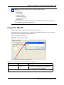
Lines . . . . . . . . . . . . . . . . . . . . . . . . . . . . . . . . . . . . . . . . . . . . . . . . . . . . . . . . . . 426
Media gateways . . . . . . . . . . . . . . . . . . . . . . . . . . . . . . . . . . . . . . . . . . . . . . . . . 426
T.38 Fax restrictions . . . . . . . . . . . . . . . . . . . . . . . . . . . . . . . . . . . . . . . . . . . . . . . . . 427
Operational notes and restrictions . . . . . . . . . . . . . . . . . . . . . . . . . . . . . . . . . . . 427
Chapter 48
Setting up VoIP trunks for fallback . . . . . . . . . . . . . . . . . . . . . . . . . . . . . . 429
Configuring routes for fallback . . . . . . . . . . . . . . . . . . . . . . . . . . . . . . . . . . . . . . . . . . 429
Activating the VoIP schedule for fallback . . . . . . . . . . . . . . . . . . . . . . . . . . . . . . 433
Deactivating the VoIP schedule . . . . . . . . . . . . . . . . . . . . . . . . . . . . . . . . . . . . . 434
Example: A private network configured for fallback . . . . . . . . . . . . . . . . . . . . . . . . . . 434
Chapter 49
Port ranges overview. . . . . . . . . . . . . . . . . . . . . . . . . . . . . . . . . . . . . . . . . . 439
RTP over UDP . . . . . . . . . . . . . . . . . . . . . . . . . . . . . . . . . . . . . . . . . . . . . . . . . . . . . . 439
UDP . . . . . . . . . . . . . . . . . . . . . . . . . . . . . . . . . . . . . . . . . . . . . . . . . . . . . . . . . . . . . . 439
Signaling Ports . . . . . . . . . . . . . . . . . . . . . . . . . . . . . . . . . . . . . . . . . . . . . . . . . . . . . 439
N0060606
Contents
21
Chapter 50
Port Ranges Panel . . . . . . . . . . . . . . . . . . . . . . . . . . . . . . . . . . . . . . . . . . . . 441
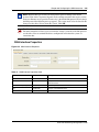
RTP over UDP Port Ranges . . . . . . . . . . . . . . . . . . . . . . . . . . . . . . . . . . . . . . . . . . . 441
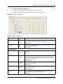
UDP Port Ranges . . . . . . . . . . . . . . . . . . . . . . . . . . . . . . . . . . . . . . . . . . . . . . . . . . . 443
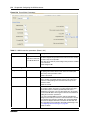
Signaling Port Ranges . . . . . . . . . . . . . . . . . . . . . . . . . . . . . . . . . . . . . . . . . . . . . . . . 444
Chapter 51
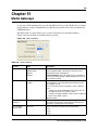
Media Gateways . . . . . . . . . . . . . . . . . . . . . . . . . . . . . . . . . . . . . . . . . . . . . . 445
Chapter 52
Call security and remote access . . . . . . . . . . . . . . . . . . . . . . . . . . . . . . . . 447
Defining restriction filters . . . . . . . . . . . . . . . . . . . . . . . . . . . . . . . . . . . . . . . . . . . . . . 447
Notes about restriction filters . . . . . . . . . . . . . . . . . . . . . . . . . . . . . . . . . . . . . . . . 447
Restriction filter examples . . . . . . . . . . . . . . . . . . . . . . . . . . . . . . . . . . . . . . . . . . 450
Remote call-in programming . . . . . . . . . . . . . . . . . . . . . . . . . . . . . . . . . . . . . . . . . . . 451
Creating Direct Inward System Access (DISA) . . . . . . . . . . . . . . . . . . . . . . . . . . 451
Defining remote access packages . . . . . . . . . . . . . . . . . . . . . . . . . . . . . . . . . . . . . . . 454
Defining CoS passwords . . . . . . . . . . . . . . . . . . . . . . . . . . . . . . . . . . . . . . . . . . . . . . 454
External access tones . . . . . . . . . . . . . . . . . . . . . . . . . . . . . . . . . . . . . . . . . . . . . 455
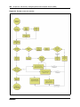
Chapter 53
Call Security: Configuring Direct Inward System Access (DISA) . . . . . . 457
Remote access overview . . . . . . . . . . . . . . . . . . . . . . . . . . . . . . . . . . . . . . . . . . . . . . 457
Setting up remote access on lines . . . . . . . . . . . . . . . . . . . . . . . . . . . . . . . . . . . . . . . 459
Remote access on loop start trunks . . . . . . . . . . . . . . . . . . . . . . . . . . . . . . . . . . 459
Remote access on T1 DID trunks . . . . . . . . . . . . . . . . . . . . . . . . . . . . . . . . . . . . 459
Chapter 54
Call security: Restriction filters . . . . . . . . . . . . . . . . . . . . . . . . . . . . . . . . . 463
Restriction filters . . . . . . . . . . . . . . . . . . . . . . . . . . . . . . . . . . . . . . . . . . . . . . . . . . . . 463
Adding a restriction filter and exceptions . . . . . . . . . . . . . . . . . . . . . . . . . . . . . . 465
Default filters . . . . . . . . . . . . . . . . . . . . . . . . . . . . . . . . . . . . . . . . . . . . . . . . . . . . 466
Chapter 55
Call security: Remote access packages . . . . . . . . . . . . . . . . . . . . . . . . . . 469
Configuring remote access packages . . . . . . . . . . . . . . . . . . . . . . . . . . . . . . . . . . . . 469
Chapter 56
Configuring CoS passwords for remote access . . . . . . . . . . . . . . . . . . . . 473
Class of Service table . . . . . . . . . . . . . . . . . . . . . . . . . . . . . . . . . . . . . . . . . . . . . . . . 473
Adding or modifying a CoS password values . . . . . . . . . . . . . . . . . . . . . . . . . . . 474
Notes about CoS passwords . . . . . . . . . . . . . . . . . . . . . . . . . . . . . . . . . . . . . . . . 475
CoS examples . . . . . . . . . . . . . . . . . . . . . . . . . . . . . . . . . . . . . . . . . . . . . . . . . . . 476
External access tones . . . . . . . . . . . . . . . . . . . . . . . . . . . . . . . . . . . . . . . . . . . . . 477
BCM 4.0 Networking Configuration Guide
22
Contents
Chapter 57
Data networking overview. . . . . . . . . . . . . . . . . . . . . . . . . . . . . . . . . . . . . . 479
What is data networking? . . . . . . . . . . . . . . . . . . . . . . . . . . . . . . . . . . . . . . . . . . . . . 479
About the BCM VoIP capability . . . . . . . . . . . . . . . . . . . . . . . . . . . . . . . . . . . . . . . . . 479
Network routing . . . . . . . . . . . . . . . . . . . . . . . . . . . . . . . . . . . . . . . . . . . . . . . . . . . . . 479
Configuring the BCM with data networks . . . . . . . . . . . . . . . . . . . . . . . . . . . . . . . . . 479
Chapter 58
Prerequisites checklist . . . . . . . . . . . . . . . . . . . . . . . . . . . . . . . . . . . . . . . . 481
Network diagram . . . . . . . . . . . . . . . . . . . . . . . . . . . . . . . . . . . . . . . . . . . . . . . . . . . . 481
Network devices . . . . . . . . . . . . . . . . . . . . . . . . . . . . . . . . . . . . . . . . . . . . . . . . . . . . 482
Network assessment . . . . . . . . . . . . . . . . . . . . . . . . . . . . . . . . . . . . . . . . . . . . . . . . . 483
Resource assessment . . . . . . . . . . . . . . . . . . . . . . . . . . . . . . . . . . . . . . . . . . . . . . . . 483
Keycodes . . . . . . . . . . . . . . . . . . . . . . . . . . . . . . . . . . . . . . . . . . . . . . . . . . . . . . . . . . 484
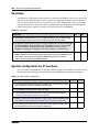
System configuration for IP functions . . . . . . . . . . . . . . . . . . . . . . . . . . . . . . . . . . . . 484
Finding the published IP address . . . . . . . . . . . . . . . . . . . . . . . . . . . . . . . . . . . . . . . 485
Media gateway parameters for IP service . . . . . . . . . . . . . . . . . . . . . . . . . . . . . . . . . 488
VoIP trunks . . . . . . . . . . . . . . . . . . . . . . . . . . . . . . . . . . . . . . . . . . . . . . . . . . . . . . . . 490
IP telephone records . . . . . . . . . . . . . . . . . . . . . . . . . . . . . . . . . . . . . . . . . . . . . . . . . 490
Chapter 59
Configuring the LAN resources . . . . . . . . . . . . . . . . . . . . . . . . . . . . . . . . . 493
LAN resources . . . . . . . . . . . . . . . . . . . . . . . . . . . . . . . . . . . . . . . . . . . . . . . . . . . . . . 493
Configuring LAN resources . . . . . . . . . . . . . . . . . . . . . . . . . . . . . . . . . . . . . . . . . . . . 495
LAN interfaces . . . . . . . . . . . . . . . . . . . . . . . . . . . . . . . . . . . . . . . . . . . . . . . . . . . 495
IP Settings . . . . . . . . . . . . . . . . . . . . . . . . . . . . . . . . . . . . . . . . . . . . . . . . . . . . . . 497
Configuring the LAN as a DHCP Client . . . . . . . . . . . . . . . . . . . . . . . . . . . . . . . . 498
Configuring multiple IP addresses for the LAN interface . . . . . . . . . . . . . . . . . . 499
Chapter 60
Configuring the WAN resources. . . . . . . . . . . . . . . . . . . . . . . . . . . . . . . . . 503
Permanent WAN connection . . . . . . . . . . . . . . . . . . . . . . . . . . . . . . . . . . . . . . . . . . . 503
Viewing WAN resources . . . . . . . . . . . . . . . . . . . . . . . . . . . . . . . . . . . . . . . . . . . . . . 505
Configuring the WAN interfaces . . . . . . . . . . . . . . . . . . . . . . . . . . . . . . . . . . . . . . . . 505
Configuring WAN summary parameters . . . . . . . . . . . . . . . . . . . . . . . . . . . . . . . 505
WAN Interface Properties . . . . . . . . . . . . . . . . . . . . . . . . . . . . . . . . . . . . . . . . . . 507
WAN IP Address . . . . . . . . . . . . . . . . . . . . . . . . . . . . . . . . . . . . . . . . . . . . . . . . . 508
Setting WAN T1 Parameters . . . . . . . . . . . . . . . . . . . . . . . . . . . . . . . . . . . . . . . . 508
Setting WAN Sync Parameters . . . . . . . . . . . . . . . . . . . . . . . . . . . . . . . . . . . . . . 510
Setting WAN Frame Relay Parameters . . . . . . . . . . . . . . . . . . . . . . . . . . . . . . . 511
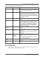
PVC Configuration . . . . . . . . . . . . . . . . . . . . . . . . . . . . . . . . . . . . . . . . . . . . . . . . . . . 513
WAN PPP Parameters . . . . . . . . . . . . . . . . . . . . . . . . . . . . . . . . . . . . . . . . . . . . 516
Multilink PPP Parameters . . . . . . . . . . . . . . . . . . . . . . . . . . . . . . . . . . . . . . . . . . 519
N0060606
Contents
23
Configuring multiple IP addresses for a WAN interface . . . . . . . . . . . . . . . . . . . 521
Configuring the DLCI to IP Mapping . . . . . . . . . . . . . . . . . . . . . . . . . . . . . . . . . . 523
Chapter 61
Data modules . . . . . . . . . . . . . . . . . . . . . . . . . . . . . . . . . . . . . . . . . . . . . . . . 525
Configuring the DDI Mux module . . . . . . . . . . . . . . . . . . . . . . . . . . . . . . . . . . . . . . . 525
DDI Mux features . . . . . . . . . . . . . . . . . . . . . . . . . . . . . . . . . . . . . . . . . . . . . . . . 525
Configuring DDI Mux connections . . . . . . . . . . . . . . . . . . . . . . . . . . . . . . . . . . . . 528
Assigning the DDI Mux modules . . . . . . . . . . . . . . . . . . . . . . . . . . . . . . . . . . . . . 528
Assigning lines for voice traffic . . . . . . . . . . . . . . . . . . . . . . . . . . . . . . . . . . . . . . 529
Assigning lines to the data module . . . . . . . . . . . . . . . . . . . . . . . . . . . . . . . . . . . 529
Removing a line assignment . . . . . . . . . . . . . . . . . . . . . . . . . . . . . . . . . . . . . . . . 530
Configuring the DDI Mux to work with the DTE . . . . . . . . . . . . . . . . . . . . . . . . . . 530
Configuring a data module . . . . . . . . . . . . . . . . . . . . . . . . . . . . . . . . . . . . . . . . . . . . 532
Viewing the data module settings . . . . . . . . . . . . . . . . . . . . . . . . . . . . . . . . . . . . 532
Programming the BayStack settings . . . . . . . . . . . . . . . . . . . . . . . . . . . . . . . . . . 532
Fixed access . . . . . . . . . . . . . . . . . . . . . . . . . . . . . . . . . . . . . . . . . . . . . . . . . . . . 532
Switched access (PRI & BRI) . . . . . . . . . . . . . . . . . . . . . . . . . . . . . . . . . . . . . . . 533
Line assignment . . . . . . . . . . . . . . . . . . . . . . . . . . . . . . . . . . . . . . . . . . . . . . . . . 534
Line pool access . . . . . . . . . . . . . . . . . . . . . . . . . . . . . . . . . . . . . . . . . . . . . . . . . 535
Chapter 62
Configuring the Dial-up resources . . . . . . . . . . . . . . . . . . . . . . . . . . . . . . . 537
Dial-in . . . . . . . . . . . . . . . . . . . . . . . . . . . . . . . . . . . . . . . . . . . . . . . . . . . . . . . . . . . . 538
Modem Dial-in . . . . . . . . . . . . . . . . . . . . . . . . . . . . . . . . . . . . . . . . . . . . . . . . . . . 541
Changing the Modem Region . . . . . . . . . . . . . . . . . . . . . . . . . . . . . . . . . . . . . . . 542
ISDN Dial-in . . . . . . . . . . . . . . . . . . . . . . . . . . . . . . . . . . . . . . . . . . . . . . . . . . . . 542
Dial-out . . . . . . . . . . . . . . . . . . . . . . . . . . . . . . . . . . . . . . . . . . . . . . . . . . . . . . . . . . . 543
Creating a modem interface . . . . . . . . . . . . . . . . . . . . . . . . . . . . . . . . . . . . . . . . 543
Enabling and disabling the modem interface . . . . . . . . . . . . . . . . . . . . . . . . . . . 543
Configuring a modem interface . . . . . . . . . . . . . . . . . . . . . . . . . . . . . . . . . . . . . . 544
Link Parameters . . . . . . . . . . . . . . . . . . . . . . . . . . . . . . . . . . . . . . . . . . . . . . . . . 545
IP Address Specification . . . . . . . . . . . . . . . . . . . . . . . . . . . . . . . . . . . . . . . . . . . 547
Access Parameters . . . . . . . . . . . . . . . . . . . . . . . . . . . . . . . . . . . . . . . . . . . . . . . 548
Creating an ISDN dial out interface . . . . . . . . . . . . . . . . . . . . . . . . . . . . . . . . . . . 550
Configuring an ISDN interface . . . . . . . . . . . . . . . . . . . . . . . . . . . . . . . . . . . . . . 550
ISDN Channel Characteristics . . . . . . . . . . . . . . . . . . . . . . . . . . . . . . . . . . . . . . 551
ISDN Link Parameters . . . . . . . . . . . . . . . . . . . . . . . . . . . . . . . . . . . . . . . . . . . . 552
ISDN Access Parameters . . . . . . . . . . . . . . . . . . . . . . . . . . . . . . . . . . . . . . . . . . 553
Point to Point Protocol over Ethernet (PPPoE) . . . . . . . . . . . . . . . . . . . . . . . . . . . . . 556
Settings required for PPPoE . . . . . . . . . . . . . . . . . . . . . . . . . . . . . . . . . . . . . . . . 556
Creating a PPPoE dial up interface . . . . . . . . . . . . . . . . . . . . . . . . . . . . . . . . . . . 556
BCM 4.0 Networking Configuration Guide
24
Contents
Configuring a PPPoE interface . . . . . . . . . . . . . . . . . . . . . . . . . . . . . . . . . . . . . . 557
Link Parameters . . . . . . . . . . . . . . . . . . . . . . . . . . . . . . . . . . . . . . . . . . . . . . . . . 558
IP Address Specifications . . . . . . . . . . . . . . . . . . . . . . . . . . . . . . . . . . . . . . . . . . 559
DNS Settings . . . . . . . . . . . . . . . . . . . . . . . . . . . . . . . . . . . . . . . . . . . . . . . . . . . . 560
Access Parameters . . . . . . . . . . . . . . . . . . . . . . . . . . . . . . . . . . . . . . . . . . . . . . . 561
Deleting a PPPoE interface . . . . . . . . . . . . . . . . . . . . . . . . . . . . . . . . . . . . . . . . . 562
Auto dial-out . . . . . . . . . . . . . . . . . . . . . . . . . . . . . . . . . . . . . . . . . . . . . . . . . . . . . . . 563
Creating an auto dial-out interface . . . . . . . . . . . . . . . . . . . . . . . . . . . . . . . . . . . 564
Guidelines for using remote Dial-in . . . . . . . . . . . . . . . . . . . . . . . . . . . . . . . . . . . . . . 564
Using a dial-up interface as a primary connection . . . . . . . . . . . . . . . . . . . . . . . . . . . 564
Chapter 63
Configuring Net Link Manager . . . . . . . . . . . . . . . . . . . . . . . . . . . . . . . . . . 567
Selecting a permanent WAN link as the primary WAN connection . . . . . . . . . . . . . . 569
Selecting a dial-up link as the primary WAN connection . . . . . . . . . . . . . . . . . . . . . . 571
Chapter 64
Configuring IP Routing . . . . . . . . . . . . . . . . . . . . . . . . . . . . . . . . . . . . . . . . 573
Static routes . . . . . . . . . . . . . . . . . . . . . . . . . . . . . . . . . . . . . . . . . . . . . . . . . . . . . . . . 573
Routing Information Protocol (RIP) . . . . . . . . . . . . . . . . . . . . . . . . . . . . . . . . . . . . . . 575
Open Shortest Path First (OSPF) . . . . . . . . . . . . . . . . . . . . . . . . . . . . . . . . . . . . . . . 576
IP routing protocol precedence . . . . . . . . . . . . . . . . . . . . . . . . . . . . . . . . . . . . . . 576
Configuring IP Routing global settings . . . . . . . . . . . . . . . . . . . . . . . . . . . . . . . . . . . 576
Configuring IP routing on an interface . . . . . . . . . . . . . . . . . . . . . . . . . . . . . . . . . . . . 579
Configuring RIP parameters on a network interface . . . . . . . . . . . . . . . . . . . . . . 579
Configuring OSPF Parameters on a network interface . . . . . . . . . . . . . . . . . . . . 583
OSPF NBMA Neighbors . . . . . . . . . . . . . . . . . . . . . . . . . . . . . . . . . . . . . . . . . . . 586
Restarting the router . . . . . . . . . . . . . . . . . . . . . . . . . . . . . . . . . . . . . . . . . . . . . . 587
Chapter 65
Configuring DHCP . . . . . . . . . . . . . . . . . . . . . . . . . . . . . . . . . . . . . . . . . . . . 589
DHCP configuration overview . . . . . . . . . . . . . . . . . . . . . . . . . . . . . . . . . . . . . . . 589
Configuring the DHCP Mode . . . . . . . . . . . . . . . . . . . . . . . . . . . . . . . . . . . . . . . . . . . 590
Configuring a DHCP Server . . . . . . . . . . . . . . . . . . . . . . . . . . . . . . . . . . . . . . . . . . . 590
LAN settings for DHCP Server . . . . . . . . . . . . . . . . . . . . . . . . . . . . . . . . . . . . . . . . . 593
Configuring Address ranges for a Local Scope . . . . . . . . . . . . . . . . . . . . . . . . . . 594
Remote Scope . . . . . . . . . . . . . . . . . . . . . . . . . . . . . . . . . . . . . . . . . . . . . . . . . . . . . . 600
Remote Scope . . . . . . . . . . . . . . . . . . . . . . . . . . . . . . . . . . . . . . . . . . . . . . . . . . 600
Modifying Remote Scope general settings . . . . . . . . . . . . . . . . . . . . . . . . . . . . . 601
Configuring Address ranges for a Remote Scope . . . . . . . . . . . . . . . . . . . . . . . . 601
Configuring Remote Scope Reserved Addresses . . . . . . . . . . . . . . . . . . . . . . . . 603
Remote Scope Lease Information . . . . . . . . . . . . . . . . . . . . . . . . . . . . . . . . . . . . 604
To delete a Remote Scope reserved address . . . . . . . . . . . . . . . . . . . . . . . . . . . 605
N0060606
Contents
25
Configuring a DHCP Relay Agent . . . . . . . . . . . . . . . . . . . . . . . . . . . . . . . . . . . . . . . 605
DHCP Server list . . . . . . . . . . . . . . . . . . . . . . . . . . . . . . . . . . . . . . . . . . . . . . . . . 606
LAN settings for DHCP Relay Agent . . . . . . . . . . . . . . . . . . . . . . . . . . . . . . . . . . . . . 607
Configuring IP Terminal DHCP Options . . . . . . . . . . . . . . . . . . . . . . . . . . . . . . . . . . 608
Chapter 66
Configuring NAT (Network Address Translation) . . . . . . . . . . . . . . . . . . . 613
Enabling and disabling NAT . . . . . . . . . . . . . . . . . . . . . . . . . . . . . . . . . . . . . . . . . . . 614
Configuring an Interface with NAT . . . . . . . . . . . . . . . . . . . . . . . . . . . . . . . . . . . . . . . 614
Adding a Rule to an interface . . . . . . . . . . . . . . . . . . . . . . . . . . . . . . . . . . . . . . . 616
Modifying a Rule to an Interface . . . . . . . . . . . . . . . . . . . . . . . . . . . . . . . . . . . . . 619
Deleting a Rule to an Interface . . . . . . . . . . . . . . . . . . . . . . . . . . . . . . . . . . . . . . 620
Assigning filters to accounts . . . . . . . . . . . . . . . . . . . . . . . . . . . . . . . . . . . . . . . . 620
Configuring NAT to change the source IP address used for WAN traffic . . . . . . 621
Chapter 67
Configuring IP Filter Rules . . . . . . . . . . . . . . . . . . . . . . . . . . . . . . . . . . . . . 623
Default Rules . . . . . . . . . . . . . . . . . . . . . . . . . . . . . . . . . . . . . . . . . . . . . . . . . . . . . . . 623
Configuring IP Filters for an interface . . . . . . . . . . . . . . . . . . . . . . . . . . . . . . . . . . . . 625
Inbound Rules . . . . . . . . . . . . . . . . . . . . . . . . . . . . . . . . . . . . . . . . . . . . . . . . . . . . . . 627
Adding an Inbound filter rule . . . . . . . . . . . . . . . . . . . . . . . . . . . . . . . . . . . . . . . . 628
Outbound Rules . . . . . . . . . . . . . . . . . . . . . . . . . . . . . . . . . . . . . . . . . . . . . . . . . . . . . 634
Traffic monitoring overview . . . . . . . . . . . . . . . . . . . . . . . . . . . . . . . . . . . . . . . . . 634
Differentiated Services (DiffServ) overview . . . . . . . . . . . . . . . . . . . . . . . . . . . . . 635
Implementing Quality of Service (QoS) . . . . . . . . . . . . . . . . . . . . . . . . . . . . . . . . 638
Adding an Outbound Filter for a Firewall Filter Interface . . . . . . . . . . . . . . . . . . . 644
Configuring the order of the inbound and outbound filters for an interface . . . . . 645
Accessing Element Manager through the Firewall . . . . . . . . . . . . . . . . . . . . . . . . . . 646
Firewall rules for BCM with Dialup interfaces . . . . . . . . . . . . . . . . . . . . . . . . . . . . . . 647
Chapter 68
Virtual Private Networks (VPN) . . . . . . . . . . . . . . . . . . . . . . . . . . . . . . . . . . 649
IPSec . . . . . . . . . . . . . . . . . . . . . . . . . . . . . . . . . . . . . . . . . . . . . . . . . . . . . . . . . . . . . 651
Encryption . . . . . . . . . . . . . . . . . . . . . . . . . . . . . . . . . . . . . . . . . . . . . . . . . . . . . . 652
IPSec capacity restrictions . . . . . . . . . . . . . . . . . . . . . . . . . . . . . . . . . . . . . . . . . 654
Settings required for IPSec tunnels . . . . . . . . . . . . . . . . . . . . . . . . . . . . . . . . . . . 654
Changing the IPSec global settings . . . . . . . . . . . . . . . . . . . . . . . . . . . . . . . . . . 661
IPSec Branch Office Tunnel configuration . . . . . . . . . . . . . . . . . . . . . . . . . . . . . 664
Branch Office IPSec Tunnel . . . . . . . . . . . . . . . . . . . . . . . . . . . . . . . . . . . . . . . . 664
Local Accessible Networks to the Branch Office IPSec tunnel. . . . . . . . . . . . . . 668
Modifying a Branch Office IPSec Tunnel . . . . . . . . . . . . . . . . . . . . . . . . . . . . . . 670
Modifying Local Accessible Networks to the Branch Office IPSec tunnel . . . . . . 671
Modifying Remote Accessible Networks to the Branch Office IPSec tunnel . . . . 671
BCM 4.0 Networking Configuration Guide
26
Contents
Deleting a Branch Office IPSec tunnel . . . . . . . . . . . . . . . . . . . . . . . . . . . . . . . . 672
Creating a tunnel between two BCMs . . . . . . . . . . . . . . . . . . . . . . . . . . . . . . . . . 673
IPSec Remote User Tunnel configuration . . . . . . . . . . . . . . . . . . . . . . . . . . . . . . 674
Adding a Remote User IPSec Tunnel . . . . . . . . . . . . . . . . . . . . . . . . . . . . . . . . . 677
Remote User Tunnels . . . . . . . . . . . . . . . . . . . . . . . . . . . . . . . . . . . . . . . . . . . . . 678
Split Tunnel Networks . . . . . . . . . . . . . . . . . . . . . . . . . . . . . . . . . . . . . . . . . . . . . 682
IP Address Pool . . . . . . . . . . . . . . . . . . . . . . . . . . . . . . . . . . . . . . . . . . . . . . . . . 684
Chapter 69
Configuring DNS . . . . . . . . . . . . . . . . . . . . . . . . . . . . . . . . . . . . . . . . . . . . . 687
DNS proxy . . . . . . . . . . . . . . . . . . . . . . . . . . . . . . . . . . . . . . . . . . . . . . . . . . . . . . 687
DNS client . . . . . . . . . . . . . . . . . . . . . . . . . . . . . . . . . . . . . . . . . . . . . . . . . . . . . . 687
Chapter 70
Configuring Web Cache . . . . . . . . . . . . . . . . . . . . . . . . . . . . . . . . . . . . . . . 691
Guidelines for using Web caching/Proxy . . . . . . . . . . . . . . . . . . . . . . . . . . . . . . . . . . 691
Important Web Cache considerations . . . . . . . . . . . . . . . . . . . . . . . . . . . . . . . . . . . . 694
Chapter 71
Configuring QoS (Quality of Service) Queuing . . . . . . . . . . . . . . . . . . . . . 695
Queuing . . . . . . . . . . . . . . . . . . . . . . . . . . . . . . . . . . . . . . . . . . . . . . . . . . . . . . . . . . . 695
Configuring QoS Queuing . . . . . . . . . . . . . . . . . . . . . . . . . . . . . . . . . . . . . . . . . . . . . 695
QoS accounts . . . . . . . . . . . . . . . . . . . . . . . . . . . . . . . . . . . . . . . . . . . . . . . . . . . 699
Chapter 72
VLAN overview . . . . . . . . . . . . . . . . . . . . . . . . . . . . . . . . . . . . . . . . . . . . . . . 701
Choosing DHCP for VLAN . . . . . . . . . . . . . . . . . . . . . . . . . . . . . . . . . . . . . . . . . . . . . 701
Specifying the site-specific options for VLAN . . . . . . . . . . . . . . . . . . . . . . . . . . . . . . 701
Appendix A
Silence suppression . . . . . . . . . . . . . . . . . . . . . . . . . . . . . . . . . . . . . . . . . . 703
Silence suppression on half-duplex links . . . . . . . . . . . . . . . . . . . . . . . . . . . . . . . . . . 703
Silence suppression on full-duplex links . . . . . . . . . . . . . . . . . . . . . . . . . . . . . . . . . . 705
Comfort noise . . . . . . . . . . . . . . . . . . . . . . . . . . . . . . . . . . . . . . . . . . . . . . . . . . . . . . 707
Appendix B
ISDN overview . . . . . . . . . . . . . . . . . . . . . . . . . . . . . . . . . . . . . . . . . . . . . . . 709
Welcome to ISDN . . . . . . . . . . . . . . . . . . . . . . . . . . . . . . . . . . . . . . . . . . . . . . . . . . . 709
Analog versus ISDN . . . . . . . . . . . . . . . . . . . . . . . . . . . . . . . . . . . . . . . . . . . . . . 709
Types of ISDN service . . . . . . . . . . . . . . . . . . . . . . . . . . . . . . . . . . . . . . . . . . . . 710
ISDN layers . . . . . . . . . . . . . . . . . . . . . . . . . . . . . . . . . . . . . . . . . . . . . . . . . . . . . 710
ISDN bearer capability . . . . . . . . . . . . . . . . . . . . . . . . . . . . . . . . . . . . . . . . . . . . 711
Services and features for ISDN BRI and PRI . . . . . . . . . . . . . . . . . . . . . . . . . . . . . . 711
N0060606
Contents
27
PRI services and features . . . . . . . . . . . . . . . . . . . . . . . . . . . . . . . . . . . . . . . . . . 711
BRI services and features . . . . . . . . . . . . . . . . . . . . . . . . . . . . . . . . . . . . . . . . . . 712
Service provider features . . . . . . . . . . . . . . . . . . . . . . . . . . . . . . . . . . . . . . . . . . 712
Network name display . . . . . . . . . . . . . . . . . . . . . . . . . . . . . . . . . . . . . . . . . . . . . 713
Name and number blocking (ONN) . . . . . . . . . . . . . . . . . . . . . . . . . . . . . . . . . . . 713
Call by Call Service Selection for PRI . . . . . . . . . . . . . . . . . . . . . . . . . . . . . . . . . 713
Emergency 911 dialing . . . . . . . . . . . . . . . . . . . . . . . . . . . . . . . . . . . . . . . . . . . . 714
2-way DID . . . . . . . . . . . . . . . . . . . . . . . . . . . . . . . . . . . . . . . . . . . . . . . . . . . . . . 715
Dialing plan and PRI . . . . . . . . . . . . . . . . . . . . . . . . . . . . . . . . . . . . . . . . . . . . . . 715
ISDN hardware . . . . . . . . . . . . . . . . . . . . . . . . . . . . . . . . . . . . . . . . . . . . . . . . . . . . . 715
PRI hardware . . . . . . . . . . . . . . . . . . . . . . . . . . . . . . . . . . . . . . . . . . . . . . . . . . . 715
BRI hardware . . . . . . . . . . . . . . . . . . . . . . . . . . . . . . . . . . . . . . . . . . . . . . . . . . . 716
S Reference Point . . . . . . . . . . . . . . . . . . . . . . . . . . . . . . . . . . . . . . . . . . . . . . . . 716
T Reference Points . . . . . . . . . . . . . . . . . . . . . . . . . . . . . . . . . . . . . . . . . . . . . . . 716
Clock source for ISDN . . . . . . . . . . . . . . . . . . . . . . . . . . . . . . . . . . . . . . . . . . . . . 717
ISDN BRI NT1 equipment . . . . . . . . . . . . . . . . . . . . . . . . . . . . . . . . . . . . . . . . . . 717
ISDN standards compatibility . . . . . . . . . . . . . . . . . . . . . . . . . . . . . . . . . . . . . . . . . . 718
Planning your ISDN network . . . . . . . . . . . . . . . . . . . . . . . . . . . . . . . . . . . . . . . . . . . 718
Ordering ISDN PRI . . . . . . . . . . . . . . . . . . . . . . . . . . . . . . . . . . . . . . . . . . . . . . . . . . 718
Ordering ISDN BRI . . . . . . . . . . . . . . . . . . . . . . . . . . . . . . . . . . . . . . . . . . . . . . . . . . 718
Supported ISDN protocols . . . . . . . . . . . . . . . . . . . . . . . . . . . . . . . . . . . . . . . . . . . . . 720
Appendix C
Codec rates. . . . . . . . . . . . . . . . . . . . . . . . . . . . . . . . . . . . . . . . . . . . . . . . . . 721
Appendix D
Stateful Packet Filters . . . . . . . . . . . . . . . . . . . . . . . . . . . . . . . . . . . . . . . . . 723
Stateful session creation . . . . . . . . . . . . . . . . . . . . . . . . . . . . . . . . . . . . . . . . . . . 725
Index . . . . . . . . . . . . . . . . . . . . . . . . . . . . . . . . . . . . . . . . . . . . . . . . . . . . . . . 731
BCM 4.0 Networking Configuration Guide
28
Contents
N0060606
29
Chapter 1
Getting started with BCM
Refer to the following topics for general BCM information:
•
•
•
•
“About BCM”
“Symbols and conventions used in this guide” on page 33
“Related publications” on page 34
“How to get Help” on page 39
About this guide
The BCM 4.0 Networking Configuration Guide describes how to install, configure, and maintain
the BCM200, BCM400, and BCM1000 hardware running Business Communications Manager 4.0
(BCM) 4.0 software.
Purpose
The concepts, operations, and tasks described in this guide relate to the hardware of the BCM
system. This guide provides task-based information on how to configure a BCM network.
Use Element Manager, Startup Profile, and Telset Administration to configure various BCM
parameters.
In brief, the information in this guide explains:
•
•
•
•
•
•
public and private networking
configuring trunks and lines
media gateways
loops
IP settings
dialing plans
Audience
The BCM 4.0 Networking Configuration Guide is directed to installers responsible for installing,
configuring, and maintaining BCM systems.
To use this guide, you must:
•
•
•
be an authorized BCM installer/administrator within your organization
know basic Nortel BCM terminology
be knowledgeable about telephony and IP networking technology
BCM 4.0 Networking Configuration Guide
30
Chapter 1 Getting started with BCM
Acronyms
The following is a list of acronyms used in this guide.
Table 1 Acronyms (Sheet 1 of 2)
Acronym
Description
AH
authentication header
ARP
address resolution protocol
ARS
automatic route selection
ASM
analog station module
ATA
analog terminal adapter
BCM
Business Communications Manager
BRI
basic rate interface
CbC
Call-by-call
CoS
Class of Service
CLID
calling line identification
CLIR
calling line information restriction
CRC
cyclic redundancy check
CSU
Channel Service Unit
DHCP
Dynamic host configuration protocol
DID
direct inward dial
DISA
direct inward system access
DLCI
data link connection identifier
DNS
domain name server
DTMF
dual tone multi-frequency
FEM
fiber expansion module
FoIP
fax over IP
MCDN
Meridian customer defined networking
MCID
malicious call identification
MSC
media services card
NAT
network address translation
OLI
outgoing line identification
ONN
outgoing name and number
OSPF
open shortest path first
PFS
perfect forward security
PPPoE
point to point over Ethernet
QoS
quality of service
RIP
routing information protocol
SIP
session initiated protocol
N0060606
Chapter 1 Getting started with BCM
31
Table 1 Acronyms (Sheet 2 of 2)
Acronym
Description
SRG
survivable remote gateway
TAT
trunk anti-tromboning
TTL
time to live
UDP
universal dialing plan
VAD
voice activity detection
VLAN
virtual LAN
VoIP
voice over IP
Organization
This guide is organized for easy access to information that explains the concepts, operations, and
procedures associated with the BCM system.
About BCM
The BCM system provides private network and telephony management capability to small and
medium-sized businesses.
The BCM system:
•
•
integrates voice and data capabilities, VoIP gateway functions, and QoS data-routing features
into a single telephony system
enables you to create and provide telephony applications for use in a business environment
BCM key hardware elements
BCM includes the following key elements:
•
•
•
•
•
•
BCM200 main unit
BCM400 main unit
BCM1000 main unit
BCM expansion unit (compatible with BCM400 main unit)
BCM400 expansion gateway
BCM media bay modules (MBM):
— 4x16
— ASM8, ASM8+
— BRIM
— CTM4, CTM8
— DDIM
— DSM16+, DSM32+
BCM 4.0 Networking Configuration Guide
32
Chapter 1 Getting started with BCM
—
—
—
—
DTM
FEM
GASM
GATM4, GATM8
BCM features
BCM supports the complete range of IP telephony features offered by existing BCM products:
Note: You enable the following features by entering the appropriate keycodes (no
additional hardware is required).
•
•
VoIP Gateway: Up to 12 VoIP trunks
VoIP Telephony Clients: Up to 64 VoIP Telephony clients, supporting the range of Nortel
IP Phones.
BCM applications
BCM supports many applications provided on the existing BCM platforms.
Note: You enable the following features by entering the appropriate keycodes (no
additional hardware is required).
•
•
•
•
•
•
•
•
•
N0060606
Voice Messaging for standard voice mail and auto-attendant features
Unified Messaging providing integrated voice mail management between voice mail and
common e-mail applications
Fax Suite providing support for attached analog fax devices
Voice Networking features
LAN CTE (computer telephony engine)
VEWAN (Voice Enabled WAN)
IVR (Integrated Voice Response)
IP Music
Intelligent Contact Center
Chapter 1 Getting started with BCM
33
Symbols and conventions used in this guide
These symbols are used to highlight critical information for the BCM system:
Caution: Alerts you to conditions where you can damage the equipment.
Danger: Alerts you to conditions where you can get an electrical shock.
Warning: Alerts you to conditions where you can cause the system to fail or work
improperly.
Note: Alerts you to important information.
Tip: Alerts you to additional information that can help you perform a task.
!
Security Note: Indicates a point of system security where a default should be
changed, or where the administrator needs to make a decision about the level of
security required for the system.
Warning: Alerts you to ground yourself with an antistatic grounding strap
before performing the maintenance procedure.
Warning: Alerts you to remove the BCM main unit and expansion unit power
cords from the ac outlet before performing any maintenance procedure.
BCM 4.0 Networking Configuration Guide
34
Chapter 1 Getting started with BCM
The following conventions and symbols are used to represent the Business Series Terminal display
and dialpad.
Convention
Example
Used for
Word in a special font (shown in
the top line of the display)
Pswd:
Command line prompts on display telephones.
Underlined word in capital letters
(shown in the bottom line of a
two-line display telephone)
PLAY
Display option. Available on two line display
telephones. Press the button directly below the
option on the display to proceed.
Dialpad buttons
Buttons you press on the dialpad to select a
particular option.
The following text conventions are used in this guide to indicate the information described:
Convention
Description
bold Courier
text
Indicates command names and options and text that you must enter.
Example: Use the info command.
Example: Enter show ip {alerts|routes}.
italic text
Indicates book titles.
plain Courier
text
Indicates command syntax and system output (for example, prompts
and system messages).
Example: Set Trap Monitor Filters
FEATURE
HOLD
RELEASE
Indicates that you press the button with the coordinating icon on
whichever set you are using.
Related publications
This section provides a list of additional documents referred to in this guide. There are two types
of publications: Technical Documents on page 34 and User Guides on page 36.
Technical Documents
BCM 4.0 System Overview (N0060607)
System Installation
BCM 3.x to BCM 4.0 Upgrade Guide (N0060597)
BCM 4.0 Installation Checklist and Quick Start Guide (N0060602)
BCM1000 BCM 3.7 Installation and Maintenance Guide (N0008587 01)
BCM 4.0 for BCM1000 Installation and Maintenance Guide Addendum (N0060603)
N0060606
Chapter 1 Getting started with BCM
35
BCM200/400 BCM 4.0 Installation and Maintenance Guide (N0060612)
Keycode Installation Guide (N0060625)
BCM R2MFC Installation and Configuration Guide (N0027684)
Project Management Guide (N0060632)
System Programming
BCM 4.0 Administration Guide (N0060598)
BCM 4.0 Device Configuration Guide (N0060600)
BCM 4.0 Networking Configuration Guide (N0060606)
BCM 4.0 Telset Administration Guide (N0060610)
Telephones and Peripherals
BCM 4.0 Telephony Device Installation Guide (N0060609)
BST Doorphone Installation and Configuration Guide (P1013654)
T24 KIM Installation Card (P0603481)
IP Key Expansion Module (KEM) User Guide
Digital Mobility
DECT Deployment and Demonstration Tool
Digital Mobility System Installation and Configuration Guide (N0000623)
T7406 Cordless Handset Installation Guide (P0606142)
2G4 Deployment and Demonstration Tool (N0027187)
IP Telephony
i2050 Software Phone Installation Guide (N0022555)
IP Phone 1120E User Guide (NN-10300-062)
IP Phone 1140E User Guide (NN-10300-064)
IP Audio Conference Phone 2033 User Guide (N0060623)
WLAN IP Telephony Installation and Configuration Guide (N0060634)
Call Pilot
BCM 4.0 Unified Messaging Configuration Guide (N0060611)
CallPilot Fax Set Up and Operation Guide (P0606017)
CallPilot Manager Set Up and Operation Guide (N0027247)
CallPilot Message Networking Set Up and Operation Guide (N0027249)
BCM 4.0 Networking Configuration Guide
36
Chapter 1 Getting started with BCM
CallPilot Programming Record (N0027404)
CallPilot Reference Guide (N0060617)
CallPilot Telephone Administration Guide (N0060618)
Contact Center
ipView Software Wallboard Set Up and Operation Guide (N0027284)
Contact Center Reports Explained (N0060635)
Contact Center Set Up and Operation Guide (N0060620)
Multimedia Contact Center Set Up and Operation Guide (N0060626)
Multimedia Contact Center Web Developer Guide (N0060627)
Reporting for Contact Center Set up and Operations Guide (N0060637)
Upgrading from Call Center Reporting to Reporting for Contact Center (N0060638)
CallPilot Contact Center Telephone Administration Guide (N0060615)
IVR
Media Processing Server Series COMMGR Reference Manual (P0988083)
PeriReporter User’s Guide (P0988093)
PeriView Reference Manual (P0988094)
IVR Installation and Configuration Guide (N0060624)
BCM IVR Integration Supplement (P0995957)
Other Applications
BCM 4.0 LAN CTE Configuration Guide (N0060604)
BCM 4.0 Call Detail Recording System Administration Guide (N0060599)
Consolidated Reporting Data (N0064482)
BCM Imaging Tool User Guide (P0609711)
User Guides
Telephones and Peripherals
BCM 4.0 Telephone Features User Guide (N0060608)
BST Doorphone User Guide (P0605668)
Central Answering Position (CAP) User Guide (P0603480)
Hospitality Features Card (N0027326)
System-wide Call Appearance (SWCA) Features Card (N0027186)
N0060606
Chapter 1 Getting started with BCM
37
T7000 Telephone User Card (P0912061)
T7100 Telephone User Card (P0609621)
T7208 Telephone User Card (P0609622)
T7316 Telephone User Card (P0935248)
T7316E Telephone User Card (P0609623)
Digital Mobility
DECT 413X/414X Handset User Guide (N0028550)
Digital Mobility Phone 7420 User Guide (N0000635)
Digital Mobility Phone 7430/7440 User Guide (N0028550)
T7406 Cordless Telephone User Card (P0942259)
IP Telephony
IP Audio Conference Phone 2033 User Guide (N0060623)
IP Phone 2001 User Guide (N0027313)
IP Phone 2002 User Guide (N0027300)
IP Phone 2004 User Guide (N0027284)
IP Phone 2007 User Guide (N0064498)
BCM WLAN 2210/2211/2212 Handset User Guide (N0009103)
Call Pilot
CallPilot 2.5 Unified Messaging User Guide for Internet Clients
CallPilot 2.5 Unified Messaging User Guide for Lotus Notes
CallPilot 2.5 Unified Messaging User Guide for Microsoft Outlook
CallPilot 2.5 Unified Messaging User Guide for Novell GroupWise
CallPilot Fax User Guide (N0027227)
CallPilot Message Networking User Guide (N0027253)
CallPilot Quick Reference Card - CP Interface (N0027401)
CallPilot Quick Reference Card - NVM Interface (N0027379)
CallPilot Quick Reference Card - Remote Users (CP Interface) (N0027359)
CallPilot Quick Reference Card - Remote Users (NVM Interface) (N0027346)
Contact Center
Contact Center Agent Guide (N0060619)
BCM 4.0 Networking Configuration Guide
38
Chapter 1 Getting started with BCM
Contact Center Supervisor Guide (N0060621)
Other Applications
BCM 4.0 Personal Call Manager User Guide (N0027256 02)
CallPilot Message Networking User Guide (N0027253)
CallPilot Quick Reference Card - CP Interface (N0027401)
CallPilot Quick Reference Card - NVM Interface (N0027379)
CallPilot Quick Reference Card - Remote Users (CP Interface) (N0027359)
CallPilot Quick Reference Card - Remote Users (NVM Interface) (N0027346)
Contact Center
Contact Center Agent Guide (N0060619)
Contact Center Supervisor Guide (N0060621)
Other applications
BCM 4.0 Personal Call Manager User Guide (N0027256 02)
N0060606
Chapter 1 Getting started with BCM
39
How to get Help
This section explains how to get help for Nortel products and services.
Getting Help from the Nortel Web site
The best source of support for Nortel products is the Nortel Support Web site:
http://www.nortel.com/support
This site enables customers to:
•
•
•
•
•
download software and related tools
download technical documents, release notes, and product bulletins
sign up for automatic notification of new software and documentation
search the Support Web site and Nortel Knowledge Base
open and manage technical support cases
Getting Help over the phone from a Nortel Solutions Center
If you have a Nortel support contract and cannot find the information you require on the
Nortel Support Web site, you can get help over the phone from a Nortel Solutions Center.
In North America, call 1-800-4NORTEL (1-800-466-7835).
Outside North America, go to the Web site below and look up the phone number that applies
in your region:
http://www.nortel.com/callus
When you speak to the phone agent, you can reference an Express Routing Code (ERC) to more
quickly route your call to the appropriate support specialist. To locate the ERC for your product or
service, go to:
http://www.nortel.com/erc
Getting Help through a Nortel distributor or reseller
If you purchased a service contract for your Nortel product from a distributor or authorized
reseller, you can contact the technical support staff for that distributor or reseller.
BCM 4.0 Networking Configuration Guide
40
Chapter 1 Getting started with BCM
N0060606
41
Chapter 2
System telephony networking overview
The system supports both public and private networking for telephony traffic.
•
•
The public network is created by PSTN trunk connections from a Central Office terminating
on a telephone system such as the BCM.
A private network is created when the system is connected through dedicated PSTN lines or
VoIP trunks to other systems. This system may take several forms. At the simplest level, your
system may be behind a private PBX, which connects directly to the Central Office. A more
complicated system may be a node in a network of systems of various types, where calls not
only terminate at the system, but calls may need to be passed through the system to other
nodes unconnected to the originating node.
Refer to the following topics:
•
•
“Basic system configurations”
“Private network parameters” on page 45
Basic system configurations
In the most basic application, your system can provide support for system telephones to make and
receive calls over public network (PSTN) lines.
Two basic system telephony configurations
The following provides a broad overview of the telephony setup for a PBX and a DID system.
PBX system
This setup is for a larger offices which have fewer CO lines than there are telephones. In this case
the lines are pooled, and the line pool access is assigned to all DNs. There may also be a
designated attendant with a telephone that has all lines individually assigned.
BCM 4.0 Networking Configuration Guide
42
Chapter 2 System telephony networking overview
Figure 1 PBX system
Lines are assigned to a line pool
CO line 1
CO line 2
All telephones
are assigned
access to the line
pool for outgoing
calls
CO line 3
CO line 4
Receptionist
Assigned all lines/
appearance and
ring
Incoming calls
1
A call comes in on a line.
2
The receptionist answers the call and finds out who the call is for.
3
The receptionist transfers the call to a specific telephone (DN).
4
The person can pick up the call at that DN only.
Outgoing calls
1
User selects the intercom button or dials a line pool access code, which selects a line in the line
pool.
2
The user dials the outgoing telephone number.
DID system
This setup allows you to assign a dedicated phone number to each telephone. The CO assigns a list
of available numbers for each DID (Direct Inward Dial) line. You can change your DN range to
match these numbers, and you use target lines to match each number with a DN.
N0060606
Chapter 2 System telephony networking overview
43
Figure 2 DID system
Target line mapped to
DN (4005)
CO DID line
i.e. 769
with range of call
numbers (4005 to
4020)
Target line mapped to
DN (4006)
Target line mapped to
DN (4007)
Target line mapped to
DN (4008)
Incoming calls
1
DID trunks are assigned to be auto-answer.
Note: PRI lines are automatically set to auto-answer.
2
All DNs are assigned target lines.
3
A caller dials a system code and a DN. In the example shown above, it might be 769-4006.
4
The call comes into the trunk, which answers and maps the call on the target line assigned to
the matching received digits.
5
The DN assigned to that target line rings.
You can assign unanswered or busy telephones to Call Forward to another DN, such as a
designated attendant or a voice mail system.
Basic telephony routing
In a basic configuration, simple access codes (for example Line Pool Codes) are used to access the
PSTN network.
In a more complex configuration, more advanced destination codes are required to access multiple
PSTNs, private network resources, and remote nodes. Access to these resources enables advanced
features, such as tandem routing.
BCM 4.0 Networking Configuration Guide
44
Chapter 2 System telephony networking overview
Tandem calling to a remote PSTN
A system connected to a private network that uses dedicated circuits or VoIP circuits can allow a
user to dial directly to many other users, on different nodes, using a coordinating dialing plan.
Using a private network saves on toll charges, and local charges, as fewer PSTN accesses are
required for internal and external calling. Several nodes located on one site initiate their external
local calls to a centralized BCM having a T1 termination to the PSTN. This type of configuration
avoids multiple PSTN terminations at other local nodes.
The same tandeming concepts can be applied to inbound calls. DID numbers dialed from the
PSTN can be processed and tandem routed out of the centralized system to the localized remote
nodes. See other details on Tandem routing “Creating tandem private networks” on page 50.
Figure 3 Tandem dialing through a BCM to/from a private network
In the above example, there are three types of callers.
Each type of caller has a specific method of accessing the other two systems.
Callers using BCM
These callers can:
•
•
•
•
•
N0060606
call directly to a specific telephone
select an outgoing line to access a private network
select an outgoing line to access features that are available on the private network
select an outgoing central office line to access the public network
use all of the BCM features
Chapter 2 System telephony networking overview
45
Callers in the public network
These callers use the public lines to:
•
•
•
•
call directly to one or more BCM DNs
call into BCM and select an outgoing TIE line to access a private network
call into BCM and select an outgoing central office line to access the public network
call into BCM and use remote features
Callers in the private network node
These callers use the private lines to:
•
•
•
•
call directly to one or more BCM DNs
call into BCM and select an outgoing TIE line to access other nodes in a private network
call into BCM and select an outgoing central office line to access the public network
call into BCM and use remote features
System numbering and dialing plans
All systems on a private network must coordinate dialing plans, to ensure that calls get directed to
the correct network node. As well, routing becomes more complex, especially if the system is not
an end node and must be configured to relay calls to nodes not directly connected to the system.
The type of dialing plan supported by the network determines whether each node also requires
unique DNs.
Private network parameters
The following provides an overview of the values in the system that affect private networking.
Private networking protocols
The BCM supports the following protocols for private networking:
•
•
•
•
•
PRI: ETSI QSIG, Nortel Voice Networking (MCDN)
DPNSS (UK only)
BRI: ETSI QSIG
T1: E&M
VoIP trunks (with optional MCDN)
Note: Nortel Voice Networking (MCDN) is referred to as SL-1 in Element
Manager.
BCM 4.0 Networking Configuration Guide
46
Chapter 2 System telephony networking overview
BCM systems can be networked together using T-1, PRI or VoIP trunks. PRI SL-1 lines and VoIP
trunks also offer the opportunity to use the MCDN protocol, which provides enhanced trunking
features and end-to-end user identification. If a Meridian 1 is part of the Nortel MCDN network,
the network can also provide centralized voice mail and auto attendant off the Meridian.
MCDN note: MCDN networking requires all nodes on the network to use a common Universal
Dialing Plan (UDP) or a Coordinated Dialing Plan (CDP).
Keycode requirements
Keycodes are required to activate the protocols that are used to create private networking,
including:
•
•
VoIP Gateway keycodes
an MCDN, DPNSS, or Q. Sig keycode, if you want to use a networking protocol between the
systems
You must purchase and install these keycodes before you can create a network. Consult with your
Nortel distributor to ensure you order the correct keycodes for the type of network you want to
create.
Remote access to the network
Authorized users can access TIE lines, central office lines, and BCM features from outside the
system. Remote users accessing a private network configured over a large geographical area can
avoid toll charges.
Note: You cannot program a DISA DN or Auto DN to a VoIP trunk, as they
act as auto-answer trunks from one private network to the next. However, you
can configure VoIP line pools with remote access packages so that callers can
access telephones or the local PSTN on remote nodes on a tandemed network
that use VoIP trunks between systems.
Lines used for networking
External (trunk) lines provide the physical connection between BCM and other systems in a
private or public network.
The BCM numbers physical lines from 061 to 238. Default numbering depends on the trunk
module positioning within the BCM.
VoIP trunks: Although a VoIP gateway does not use physical lines, it is easier to think of them
that way. Therefore, in the BCM, lines 001 to 060 are used for VoIP trunk functionality.
BCM networking configurations that use PRI lines, require specific DTM modules.
•
N0060606
DTMs configured for PRI are used for incoming and outgoing calls (two-way DID). Incoming
calls are routed directly to a BCM DN that has a properly configured and assigned target line.
All outgoing calls made through PRI, are initiated using the destination codes.
Chapter 2 System telephony networking overview
•
47
DTMs configured for T1 can have digital lines configured as Groundstart, E&M, Loop,
or DID.
Target lines are virtual communication paths between trunks and telephones on the BCM system.
They are incoming lines only, and cannot be selected for outgoing calls or networking
applications. With target lines, you can concentrate incoming calls on fewer trunks. This type of
concentration is an advantage of DID lines. BCM target lines allow you to direct each DID number
to one or more telephones. VoIP trunks also require target lines to direct incoming traffic. Target
lines are numbered 241 to 492.
Telephones can be configured to have an appearance of analog lines or multiple appearances of
target lines.
Note: PRI B-channels cannot be assigned as line appearances. PRI
B-channels, or “trunks”, can only be configured into PRI line pools for
inbound routing through target lines with receive digits or outbound routing
through destination codes.
Types of private networks
There are several ways you can create private networks. Configuration can be based on such things
as cost of trunks, proximity of network nodes, size of the private network, and business
requirements for communications.
VoIP-based networking also requires an understanding of IP features such as codecs, jitter buffers,
Quality of Service (QoS) function, and silence suppression. Refer to “Silence suppression” on
page 703 for more information.
The services provided within networks is based on the type of trunks and the protocols assigned to
the trunks. All trunks within the network should be running the same protocols, to provide a
technically sound and stable network.
The following links are procedures to set up basic networks to advanced networks, using the
support protocols within BCM:
•
•
•
“Routing-based networks using T1 E&M lines” on page 47
“PRI networking using Call-by-Call services” on page 49
“PRI SL-1/Q.Sig/DPNSS and VoIP trunk networking” on page 49
Routing-based networks using T1 E&M lines
By properly planning and programming routing tables and destination codes, an installer can
create a dialing plan where T1 E&M lines between BCM systems are available to other systems in
the network
Figure 4 shows a network of three BCM systems. Two remote systems connect to a central system.
BCM 4.0 Networking Configuration Guide
48
Chapter 2 System telephony networking overview
Figure 4 Dialing plan for T1 E&M routing network
New York
Network # 2221
Received # 2221
Internal # 2221
Toronto
Network # 6221
Received # 6221
Internal # 6221
Pool N
Pool H
Pool M
T1 E&M
Pool B
T1 E&M
Santa Clara
Network # 4221
Received # 4221
Internal # 4221
Each system must be running BCM software. Each system must be equipped with target lines and
a DTM with at least one T1 E&M line.
The call appears on the auto answer line on the BCM in Santa Clara as 6-221. Because 6 is
programmed as a destination code for Toronto on the Santa Clara system, another call is placed
using route 002 from Santa Clara to Toronto. At the Toronto system, the digits 6-221 are
interpreted as a target line Private received number. The call now alerts at DN 6221 in Toronto.
Note: Network calls that use routes are subject to any restriction filters in
effect. If the telephone used to make a network call has an appearance of a line
used by the route, the call will move from the intercom button to the Line
button. The telephone used to make a network call must have access to the line
pool used by the route. Network calls are external calls, even though they are
dialed as if they were internal calls. Only the features and capabilities available
to external calls can be used.When programming a button to dial a Network
number automatically (autodial), network calls must be treated as external
numbers, even though they resemble internal telephone numbers. Routes
generally define the path between your BCM switch and another switch in
your network, not other individual telephones on that switch.
N0060606
Chapter 2 System telephony networking overview
49
PRI networking using Call-by-Call services
The example shown in Figure 5 highlights the use of PRI Call-by-Call services. It shows two
offices of a company, one in New York and one in Toronto. Each office is equipped with a BCM
system and a PRI line. Each office has to handle incoming and outgoing calls to the public
network. In addition, employees at each office often have to call colleagues in the other office.
Refer to “Private networking: PRI Call-by-Call services” on page 383 for more information.
Figure 5 PRI networking using Call-by-Call Services
New York office
Toronto office
Network # 2221
Received # 2221
Internal # 2221
DID # 763-2221
Network # 6221
Received # 6221
Internal # 6221
DID # 562-6221
BCM
PRI
Central
Office
BCM
TIE Connection
PRI
Central
Office
Public Network
To reduce long distance costs, and to allow for a coordinated dialing plan between the offices,
private lines are used to handle inter-office traffic.
If call-by-call services were not used, each BCM system might have to be equipped with the
following trunks:
•
•
•
12 T1 DID lines needed to handle peak incoming call traffic.
eight T1 E&M lines needed to handle inter-office calls.
eight lines needed to handle outgoing public calls
PRI SL-1/Q.Sig/DPNSS and VoIP trunk networking
PRI SL-1 trunks and VoIP trunks can be used to create private networks between BCM systems or
between BCM systems and larger call servers such as Meridian 1, Succession 1000/M, DMS100/
250 and CSE.
ETSI-QSIG and DPNSS private networking is configured very similarly, although network
features may be supported slightly differently due to local line and network requirements.
BCM 4.0 Networking Configuration Guide
50
Chapter 2 System telephony networking overview
If the MCDN protocol is added to this type of private network, the network provides additional
network management features, as well as allowing centralized voice mail features to be available
to all nodes on the network.
The following sections describe the different aspects of SL-1 and MCDN private networking.
•
•
•
•
•
“System dialing plans”
“Creating tandem private networks”
“Understanding MCDN network features” on page 53
“Networking with ETSI QSIG” on page 56
“Private networking with DPNSS” on page 65
The type of network you require depends on the equipment in the network, and how you want to
use the network.
•
With MCDN, you can tie a set of BCM systems together with PRI SL-1(MCDN)/ETSI-QSIG,
DPNSS or VoIP trunks to create a tandem network. This type of network provides the
additional advantage of providing private line access to local PSTNs for all the nodes on the
network.
Note: A keycode is required to use SL-1(MCDN).
System dialing plans
Both these types of networks require similar setups for dialing plans and routing. Each node must
have a way to route external calls to the adjacent node or nodes. To do this, all nodes must have the
same Private DN length.
You use routing and a private dialing plan to control calls over the network. Each example in this
section describes the routing configurations that are required to support calls over the network.
Depending on the type of dialing plan you choose, each node must also have a unique location or
steering code so the calls can be correctly routed through the nodes of the network. MCDN
networks also require a Private Network ID, which is supplied by the Meridian network
administrator to define how the Meridian system identifies each node.
Creating tandem private networks
You can tie a number of BCM systems together with SL-1 lines. This tandem network provides
you with the benefits of end-to-end name display and toll-free calling over the SL-1 private link.
Each BCM becomes a node in the network. In this type of network, you must ensure that each
BCM system, known as a node of the network, is set up to route calls internally as well as to other
nodes on the system. This means each node must have a route to the immediately adjacent node,
and the correct codes to distribute the called numbers. Each node must have a unique identification
number, which is determined by the type of dialing plan chosen for the network.
As well, you can save costs by having a public network connection to only one or two nodes, and
routing external calls from other nodes out through the local PSTN, thus avoiding toll charges for
single calls.
N0060606
Chapter 2 System telephony networking overview
51
VoIP note: You can also use VoIP trunks between some or all of the nodes. The setup is the same,
except that you need to create gateway records for each end of the trunk, and routing tables to
accommodate the gateway codes.
Routing for tandem networks
In tandem networks, each node needs to know how to route calls that do not terminate locally. To
do this, you set up routes for each connecting node by defining destination codes for each route.
If the node is also connected to the public network, the usual routing is required for that
connection.
The following tables show the routing tables for Node A and Node C for external and internal
terminating calls.
Note: The PRI and ETSI QSIG trunks are en bloc dialing lines, so all dialed
digits are collected before being dialed out.
BCM 4.0 Networking Configuration Guide
52
Chapter 2 System telephony networking overview
Table 1 Node A destination code table, external termination
Route
Absorb length
Destination code (public DNs)
4 (PSTN)
1
91604
3 (Node B)
0
91403762 (Node B)
3 (Node B)
0
91403765 (Node E)
4 (PSTN)
1
9140376* (not internal network)
4 (PSTN)
1
914037* (not internal network)
4 (PSTN)
1
91403* (not internal network)
4 (PSTN)
1
9* (not internal network)
* This wild card represents a single digit.
Table 2 Node A destination code table, internal termination
Route
Absorb length
Destination code (private DNs)
3 (Node B)
0
392 (Node B)
3 (Node B)
0
395 (Node E)
5 (Node C)
0
393 (Node C)
5 (Node C)
0
394 (Node D)
5 (Node C)
0
396 (Node F)
Table 3 Node C destination code table, external termination
Route
Absorb length
Destination code (Public DNs)
3 (Node B)
0
91613764 (Node D)
3 (Node B)
0
91613766 (Node F)
4 (PSTN)
1
9161376* (not internal network)
4 (PSTN)
1
916137* (not internal network)
4 (PSTN)
1
91613* (not internal network)
4 (PSTN)
1
9161* (not internal network)
4 (PSTN)
1
916* (not internal network)
4 (PSTN)
1
91* (not internal network)
4 (PSTN)
1
9 (not internal network)
* This wild card represents a single digit.
N0060606
Chapter 2 System telephony networking overview
53
Table 4 Node C destination code table, internal termination
Route
Absorb length
Destination code (Private DNs)
3 (Node D)
0
394 (Node D)
3 (Node D)
0
396 (Node F)
5 (Node A)
0
391 (Node A)
5 (Node A)
0
392 (Node B)
5 (Node A)
0
395 (Node E)
Understanding MCDN network features
When you connect your BCM systems through PRI-SL-1/ETSI QSIG/DPNSS or VoIP trunks, and
activate the MCDN protocol, your network provides a number of network call features. You can
use this protocol to network other BCM systems, such as the tandem system shown in the previous
section, Norstar systems, Meridian 1 systems, Succession systems, DMS 100 systems or CSE
systems.
Table 5 lists the MCDN features that are provided by all SL-1/VoIP networks where MCDN is
active. The features affect call redirection and trunking functions.
Table 5 MCDN network features
Centralized messaging
“Network Call Redirection Information” (NCRI)
Centralize trunking
“ISDN Call Connection Limitation” on page 54 (ICCL)
“Trunk Route Optimization” on page 55 (TRO)
“Trunk Anti-tromboning” on page 55 (TAT)
Network Call Redirection Information
NCRI (Network Call Redirection Information) builds on the following BCM features:
•
•
•
External Call Forward
Call Transfer
Call Forward
NCRI adds the ability to redirect a call across an MCDN network using Call Forward (All Calls,
No Answer, Busy) and Call Transfer features. The call destination also receives the necessary
redirection information. This feature allows the system to automatically redirect calls from within
a BCM system to the mail system, such as Meridian Mail, which resides outside the BCM system
on the Meridian 1.
Figure 6 shows an example of this situation, where user A calls user B on the same BCM. If user B
is busy or not answering, the call automatically gets transferred to a Meridian Mail number
(user C) across an MCDN link between the BCM system and the Meridian 1 system where the
mailboxes are set up.
BCM 4.0 Networking Configuration Guide
54
Chapter 2 System telephony networking overview
Figure 6 Network call redirection path
BCM
Meridian 1
with Meridian Mail
SL-1 MCDN
Telephone A
Original call
Telephone B
Call forwarded to Meridian Mail
ISDN Call Connection Limitation
The ICCL (ISDN Call Connection Limitation) feature piggybacks on the call initiation request and
acts as a check at transit PBX points to prevent misconfigured routes or calls with errors from
blocking channels. Also refer to “ISDN overview” on page 709.
This feature adds a transit/tandem counter to a call setup message. This counter is compared at
each transit PBX with a value programmed into the transit PBX, in a range from 0 to 31. If the call
setup counter is higher than the PBX value, the call will be blocked at the PBX system and cleared
back to the network. This prevents calls from creating loops that tie up lines.
Figure 7 demonstrates how a call might loop through a network if the system is not set up
with ICCL.
Figure 7 Call loop on system without ICCL
BCM
BCM
Meridian 1
BCM
Meridian 1
Telephone A
N0060606
Chapter 2 System telephony networking overview
55
Trunk Route Optimization
Trunk Route Optimization (TRO) finds the most direct route through the network to send a call
between nodes. This function occurs during the initial alerting phase of a call.
BCM configurations:
•
•
•
Under Configuration > Dialing Plan > Private Network, select the check box beside TRO.
Configure call routing for all optimal routes.
Configure call forward (All Calls, No Answer, Busy) or Selective Line Redirection to use the
optimal routes.
This feature avoids the following situation: A call originating from a BCM system may be
networked to a Meridian system, which, in turn, is networked to another Meridian system, which is
the destination for the call. If the call routes through the first Meridian (M1) to reach the second
Meridian (M2), two trunks are required for the call. An optimal choice is a straight connection to
M2. This finds these connections and overrides the less-efficient setup.
Figure 8 shows two call paths. The first route, through the Meridian, demonstrates how a call
might route if TRO is not active. The second route, that bypasses the Meridian, demonstrates how
TRO selects the optimum routing for a call.
Figure 8 Call paths with and without TRO
Telephone B
Meridian 1
BCM
PRI SL-1
Meridian 1
PRI SL-1
PRI SL-1
Original call (no TRO)
Forwarded call (no TRO)
Telephone C
Call path with TRO
Telephone A
Trunk Anti-tromboning
Trunk Anti-Tromboning (TAT) is a call-reroute feature that works to find better routes during a
transfer of an active call. This feature acts to prevent unnecessary tandeming and tromboning of
trunks.
Note: This feature is not applicable for alerting calls.
BCM 4.0 Networking Configuration Guide
56
Chapter 2 System telephony networking overview
Figure 9 shows how TAT reduces the line requirements. The solid line shows Telephone A calling
Telephone B and being transferred over an additional PRI line to Telephone C. With TAT active,
the same call is transferred to Telephone C over the same PRI line.
Figure 9 Call paths with and without TAT
BCM
Telephone C
BCM
Telephone A
Telephone B
Forwarded call (no TAT)
Forwarded call (using TAT)
Networking with ETSI QSIG
(ETSI QSIG applies only to international systems equipped with a DTM or BRIM. It is not
supported on VoIP)
ETSI QSIG is the European standard signaling protocol for multi-vendor peer-to-peer
communications between PBX systems and/or central offices.
Other information in this section: “ETSI Euro network services” on page 57.
Figure 10 illustrates an ETSI QSIG network. Note that this is exactly the same setup as that shown
in the MCDN section for North America. The hardware programming for ETSI QSIG is described
in Table 6. All other configurations are the same as those shown in the MCDN section for North
America.
N0060606
Chapter 2 System telephony networking overview
57
Figure 10 ETSI QSIG networking
Network # 2221
Received # 2221
Internal # 2221
Network # 6221
Received # 6221
Internal # 6221
PRI/BRI ETSI QSIG
PBX
PRI/BRI
ETSI QSIG
BCM West end branch
BCM East end branch
DN 4221
PRI (public
protocol)
Central
Office
Table 6 lists the settings for some of the hardware parameters for ETSI QSIG networking example
shown in Figure 10.
Table 6 Hardware programming for branch offices
West End office:
Hardware
programming
East End office:
DTM/BRIM PRI/BRI
Hardware
programming
DTM/BRIM
PRI/BRI
Protocol
ETSI QSIG
Protocol
ETSI QSIG
BchanSeq
Ascend
(PRI only)
BchanSeq
Ascend
(PRI only)
ClockSrc
Primary
ClockSrc
Primary
ETSI Euro network services
If your system has ETSI ISDN BRI/PRI lines, you can activate the malicious call identification
(MCID) and Network Diversion features. Advice of charge-end call (AOCE) is active if your
service provider has activated that service on the line.
BCM 4.0 Networking Configuration Guide
58
Chapter 2 System telephony networking overview
When the features are activated, users can:
•
•
•
display a call charge
redirect calls over the ETSI ISDN BRI/PRI line to the outside network
tag malicious calls
Advice of Charge-End of Call (AOCE) — AOCE is a supplementary service available from your
service provider on ETSI ISDN BRI/PRI links. This feature allows the BCM user to view the
charges for an outgoing call once the call completes. This information is also reported to the Call
Detail Reporting Application. The information can be provided in currency or charging units,
depending on how the feature is set up by your service provider.
To invoke the feature, the user presses FEATURE 818.
DPNSS 1 services
The Digital Private Network Signaling System (DPNSS 1) is a networking protocol enhancement
that extends the private networking capabilities of existing BCM systems. It is designed to offer
greater centralized functionality for operators, giving them access to BCM features over multiple
combined networks.
Note: The DPNSS feature is dependent on which region is loaded on your
system at startup and requires that a software keycode was entered to enable
the feature. The feature also requires a DTM-based connection.
Refer to the following topics:
•
•
•
“DPNSS 1 capabilities”
“DPNSS 1 features” on page 59
“Private networking with DPNSS” on page 65
DPNSS 1 allows a BCM local node, acting as a terminating node, to communicate with other
PBXs over the network. For example, corporate offices separated geographically can be linked
over DPNSS 1 to other BCM nodes, bypassing the restrictions of the PSTNs to which they may be
connected. This allows connected BCM nodes to function like a private network, with all features
of BCM accessible.
Note: BCM DPNSS 1 works as a terminating node only. BCM to BCM
DPNSS is not supported.
DPNSS 1 features can be used on any BCM telephone. On most BCM telephones, you must use
specific keys and/or enter a number code to access the features.
DPNSS 1 capabilities
A single BCM node, acting as a terminating node on the network, supports the following
capabilities over DPNSS 1 lines:
•
N0060606
Direct Dial Inward (DDI) for incoming calls.
Chapter 2 System telephony networking overview
•
•
•
•
59
Originating Line Identification (OLI) for incoming and outgoing calls:
— For incoming calls, the Calling Line Identification (CLI/CLID) information is displayed to
the user on telephones with line display. This must be configured in programming.
— For outgoing calls, the directory number of the originating party is sent out as OLI.
Terminal Line Identification (TLI) for incoming and outgoing calls. Referred to as Called Line
Identification.
Selective Line Redirect (SLR) and External Call Forward (ECF) implemented on calls
between DPNSS 1, and BRI/PRI, DASS2, and analog lines.
These remote access features are supported on DPNSS: DDI, line pool access code,
destination codes, and remote page feature codes.
Note: Keycodes are required to enable DPNSS 1.
DPNSS to Embark connections
DPNSS lines connected to an Embark switch perform call redirection/diversion using the Call
Forward feature to create a tandem link back to the switch. Since this is different from other
switches, you must select the type of switch DPNSS will be connecting to when you do module
programming.
Before you program Call Forwarding, ensure that:
•
•
Both real channels and virtual channels are provisioned.
Destination or line pool codes are programmed for the DPNSS to Embark link.
Also, during programming for Call Forward No Answer and Call Forward on Busy, when you
enter the Forward to: digits, the system performs a validation check with the switch on the
number. (Configuration > Telephony > Sets > Active Sets > Line Access > Properties tab)
DPNSS 1 features
The following features are available and can be programmed over DPNSS lines:
•
•
•
•
•
•
•
•
“Three party service” on page 60
Diversion (“Using the diversion feature” on page 61)
Redirection (“Using the Redirection feature” on page 62)
“Executive intrusion” on page 62
“Call Offer” on page 63
“Route optimization” on page 64
“Loop avoidance” on page 65
Message Waiting Indication
The following parameters can be configured for DPNNS 1 lines:
•
•
Line type
Prime set
BCM 4.0 Networking Configuration Guide
60
Chapter 2 System telephony networking overview
•
•
•
•
•
CLID set
Auto privacy
Answer mode
Auxiliary ringer
Full autohold
Some features are transparent to the user, but must be programmed to be activated. Others are
available for end-user programming at the telephone. Details about these features are given below.
Three party service
The Three Party Service allows a user, usually an operator, to take three-party conference by
calling two other parties from one telephone. Once the connection is made, the controlling party
can hang up, leaving the other two connected. They can even put one party on hold, and talk to the
other party.
If the original call is inbound to the BCM, any subsequent three-party conference will be
terminated when the BCM user drops out of the call.
For example, PSTN user A calls a BCM user.
After the call is established, the BCM user initiates a three-party conference with another PSTN
user. If the BCM user hangs up, the conference is closed and all parties are dropped from the call.
Following are the two rules:
Rule 1 - if the call is an inbound call, the BCM user can create a conference, but if they drop out,
the calls are all dropped.
Rule 2 - if the BCM initiates outbound calls to 2 parties, conferences them, the BCM user can drop
out leaving them connected.
Note: BCM does not support Hold over the DPNSS link itself. This means
that the conferenced party on the distant end of the network cannot place a
Three Party Service call on Hold.
This feature is designed to allow operators to assist in the connection of calls from one main
location.
Making a conference call
To initiate or disconnect from a conference call on a BCM system over DPNSS 1, use the
procedure described in the BCM 4.0 Device Configuration Guide (N0060600).
Note: Three Party Service is supported on model 7000 telephones, but in a
receive-only fashion. These telephone types cannot initiate Three Party
Service. For more information about these telephone types, see the BCM 4.0
Telephony Device Installation Guide (N0060609).
(model 7000 phones, supported in Europe only.)
N0060606
Chapter 2 System telephony networking overview
61
Using the diversion feature
Diversion is a DPNSS 1 feature for BCM that allows users to forward their calls to a third party on
the DPNSS 1 network. This feature is similar to Call Forward on BCM, but takes advantage of the
broader capabilities of DPNSS.
There are five variations of Diversion: Call Diversion Immediate, Call Diversion On Busy, Call
Diversion On No Reply, Bypass Call Diversion, and Follow-me Diversion. These variations are
described below:
•
•
•
•
•
Diversion Immediate diverts all calls to an alternate telephone. This function is programmed
by the user at their telephone.
Diversion On Busy diverts all calls to an alternate telephone when a telephone is busy. This
feature is programmed in the Element Manager.
Diversion On No Reply diverts calls that go unanswered after a specified amount of time. This
feature is programmed in the Element Manager.
Bypass Call Diversion overrides all call forward features active on a telephone over a DPNSS
line. An incoming call to the telephone will not be forwarded; instead, the telephone will
continue to ring as if call forward were not active. This feature is used to force a call to be
answered at that location. Bypass Call Diversion is a receive-only feature on BCM, and cannot
be used from a BCM telephone.
Follow-me Diversion is also a receive-only feature. It allows the call forwarded destination to
remotely change the BCM call forwarding programming (Call Forward All Calls [CFAC]
feature) to a different telephone.
Note: BCM CFAC must be active and the destination set/PBX system must
support the feature.
For example, user A forwards all calls to telephone B, a temporary office. Later, user A moves
on to location C. The user does not have to be at telephone A to forward calls to location C.
Using telephone B and Follow-me Diversion, the user can forward calls from A to location C.
Follow-me diversion can be cancelled from the forwarded location.
•
•
Diversion on Busy and Diversion on No Reply cannot be cancelled from the forwarded
telephone. These are programmable only by an installer and not by the user.
If multiple telephones are programmed to take a call, the first telephone to respond will act. All
other telephones responding are ignored. Therefore, if the first telephone to respond has
Diversion enabled, this feature will be invoked.
Restrictions by telephone type
•
•
•
all variations supported on BCM digital and IP telephones
ATA2/ASM8+—all variations supported on an ATA
ISDN—all variations supported on ISDN telephones, except Diversion on Busy and CFWD
Busy
BCM 4.0 Networking Configuration Guide
62
Chapter 2 System telephony networking overview
Setting Diversion
You set Diversion for DPNSS in the same way as Call Forward. You will need to enter the end DN
when prompted. You may also need to include the DPNSS 1 routing number.
Using the Redirection feature
Redirection is a DPNSS 1 feature similar to BCM Transfer Callback. Redirection lets a call
awaiting connection, or reconnection, be redirected by the originating party to an alternate
destination after a time-out period. Failed calls can also be redirected. Priority calls are not
redirected.
Note: The address to redirect depends on the history of the call. Calls that
have been transferred are redirected to the party that transferred them. In all
other cases, the address to redirect is the one registered at the PBX system
originating the redirection.
Note: BCM does not support the redirection of BCM originated calls, even
over DPNSS 1.
The Diversion on No Reply feature takes precedence over Redirection.
Restrictions by telephone type
•
•
For telephones with a single line display, the number key (#) acts as MORE and the star key (*)
acts as VIEW
ISDN—all variations supported on ISDN telephones
Setting redirection
The timer used for the network Callback feature is also used for redirection.
Executive intrusion
Executive Intrusion (EI) is a DPNSS 1 feature that allows an operator, or other calling party, to
intrude on a line when it is busy. An example of the use of this feature is to make an important
announcement when the recipient is on another call.
EI is similar in functionality to BCM Priority Call, but it is a receive-only feature on BCM
telephones. EI cannot be initiated from a BCM telephone. The person using this feature must be on
another PBX system on the DPNSS 1 network.
When EI is used to intrude on a call in progress, a three-way connection is established between the
originating party and the two parties on the call. The result is very much like a conference call.
When one of the three parties clears the line, the other two remain connected, and EI is terminated.
Restrictions by telephone type
•
N0060606
ATA2/ASM8+—supported
Chapter 2 System telephony networking overview
•
63
ISDN—not supported
The telephone receiving the intrusion displays Intrusion Call. A warning indication tone
will sound after intrusion has taken place, and the standard conference call tone will sound every
20 seconds.
Intrusion levels
Whether or not a telephone will accept or reject an Executive Intrusion request depends on the
level of intrusion protection programmed. Each telephone (DN) has an Intrusion Capability Level
(ICL) and four Intrusion Protection Levels (IPL).
When the ICL of the intruding telephone is higher than the IPLs of both telephones on the active
call, EI occurs. Nortel recommends setting the IPLs of most BCM telephones to the default of
None, Low, or Medium.
Intrusion levels are described as follows:
•
•
ICL: determines the ability of the attendant to intrude. As long as the ICL is higher than the
IPL of the wanted party, EI is allowed. Since EI is a receive-only feature, the ICL cannot be set
on BCM.
IPL: determines the ability of the attendant to refuse intrusion. If the IPL is lower than the ICL
of the originating party, EI is allowed. For general purposes, Nortel recommends setting the
IPL to None, Low, or Medium, unless intrusion is not wanted.
Call Offer
Call Offer over DPNSS 1 allows a calling party to indicate to the wanted party that there is an
incoming call available, even though there is no answer button available to present the call on the
telephone. The intended recipient can ignore, accept, or decline the offered call. Call Offer is
useful in increasing the call-coverage capability of a BCM system, and helps to lift the network
processing load. It is a receive-only capability on BCM: incoming calls would be initiated at
another PBX system on the DPNSS 1 network.
An example of Call Offer in use is an operator or attendant who has a number of calls coming in at
once. The operator can call offer one call and move to the next without waiting for the first call to
be answered.
Call Offer Displays
When a Call Offer is made by the originating exchange, the target telephone displays a message,
and a tone is heard. When an offered call arrives on telephones with line display, the user sees
XX...X wtng if the calling party ID is available and CLID is enabled. If CLID is not available
or CLID is disabled, Line XXX waiting appears (the line name associated with the call). If
there are more than 11 digits in the incoming number, only the last 10 will display.
If Call Queuing is programmed for the system, the display shows Release Line XXX.
This is the line name of the highest-priority queued call if it is an offered call.
BCM 4.0 Networking Configuration Guide
64
Chapter 2 System telephony networking overview
Restrictions by telephone type
•
•
•
model 7000 telephone — associated LED or LCD flashes, and a tone is heard (model 7000
phones, supported in Europe only.)
ATA2/ASM8+—Call Offer is supported as a Camp On feature, and a tone is heard
ISDN—not supported
Note the following general conditions and restrictions:
•
•
•
•
DND on busy must be selected (DN > Capabilities and Preferences > Capabilities tab) for a
telephone to accept Call Offer.
If CF on busy is programmed for the telephone, Call Offer is not accepted.
The target line for the telephone must be set to: If busy: busy tone, which is the default.
Call Offer does not work if sent over Manual answer lines. It is recommended that the lines be
left at the default: Auto.
User actions
The party receiving a Call Offer has three choices:
•
•
Ignore it. After a programmed time interval, the Offer request is removed.
Reject it. If the user activates Do Not Disturb on Busy (DND) when the Call Offer request is
made, the request is removed from the telephone. The calling party is informed of the
rejection.
Note: A call cannot be offered to a telephone with DND active. The line
indicator for external incoming calls still flashes.
•
Accept it. The Offer is accepted by releasing the active call.
Note: Forward on Busy takes priority over DND on Busy. Call Offer cannot
be accepted by putting an active call on hold.
Route optimization
Route Optimization is a DPNSS 1 feature for BCM that allows calls to follow the optimum route
between two end PBXs. This allows efficient use of network resources.
Route Optimization is initiated by the system and is transparent to the user. However, the user may
see a call switch from an appearance on the telephone to another appearance key or from an
intercom button to the appearance key or vice versa. This occurs when BCM receives a Route
Optimization request and initiates a new call to follow the optimal route.
If a telephone is active on a private line call, the Route Optimization call being established may go
on a public line. This will cause a loss of privacy on that line.
Data calls are rejected by Route Optimization in order to ensure the data transmission is not
affected.
N0060606
Chapter 2 System telephony networking overview
65
Certain situations result in Route Optimization not taking place. For example, calls that are using
Hold, Parking or Camp features do not undergo Route Optimization, and if a Route Optimization
call undergoes Diversion, the Route Optimization is dropped.
Setting Route Optimization
There is no system programming required for the feature when BCM is working as a terminating
PBX system. However, BCM must have a private access code programmed that maps to a valid
destination code or line pool code on DPNSS lines. Further, Allow Redirect must be selected.
Loop avoidance
Errors in the configuration of a network may make it possible for a call to be misrouted, and arrive
at a PBX system through which it has already passed. This would continue, causing a loop which
would eventually use up all of the available channels. The Loop Avoidance service permits
counting of DPNSS 1 transit PBXs and rejecting a call when the count exceeds a predetermined
limit.
Private networking with DPNSS
(International only)
DPNSS supports the Universal Dialing Plan (UDP), an international standard for sending and
receiving private numbers over networks. The UDP requires that a dialing number include the
following:
•
•
•
a Private Access Code, programmed into the system as part of the destination code table to
prevent conflicts with the internal numbering system. (Access Codes)
a Home Location Code (HLC) assigned to each PBX system, and configured as part of the
destination code (a maximum of seven digits). For each HLC, a destination code must be
programmed in the system. (Configuration > Telephony > Dialing Plan > Private
Networking)
a Directory Number (DN) assigned to each extension as a line appearance. The DN appears as
the last string segment in a dialed number. In the number 244-1111, 1111 is the DN.
A typical Private Number, using a private access code and dialed from another site on the network,
appears below.
Private Access Code + Home Location Code
+ Directory Number
= Calling Party Number
6
+ 2222
= 6-848-2222
+ 848
In this networking example, a private network is formed when several systems are connected
through a Meridian 1 and a terminating BCM system. Each site has its own HLC and a range of
DNs. Figure 11 illustrates this example.
BCM 4.0 Networking Configuration Guide
66
Chapter 2 System telephony networking overview
Table 7 shows examples of the construction of numbers used when dialing within the example
network. Note that 6 is the Private Access code.
Table 7 Calling numbers required for DPNSS network example
Calling Site
LOC/HLC
Calling Party
Number
Called Site
Dialing String
Called Party
Number
Site A
244
244 1111
Site B
6 668 2222
668 2222
Site B
668
668 2222
Site D
6 848 2222
848 2222
Site D
848
2222
Site D
2229
2229
Site C
496
496 3333
Public DN
9 563 3245
563 3245
Figure 11 DPNSS networking
Private
Network
Terminating
BCM Site A
DN # 111
LOC # 244
DPNSS
DPNSS
BCM
Site C
DN # 3333
LOC # 496
DPNSS
DPNSS
Meridian M1
LOC # 563
BCM
Site B
DN # 2222
LOC # 668
BCM Site D
DN # 2229
Extension 2222
LOC # 848
Calls are dialed and identified to the system as follows:
•
•
•
To reach a telephone inside the Private Network, at the BCM site, the user dials the DN of
choice.
To reach a telephone inside the Private Network, from another site, the user dials HLC + DN.
To reach a telephone outside the Private Network, the user dials an Access Code + HLC + DN.
Each node has its own destination (dest) code, which includes the appropriate access and HLC
codes to route the call appropriately.
N0060606
67
Chapter 3
Telephony programming: Configuring call traffic
Telephony call traffic has a number of configuration requirements. Some configuration is common
to both incoming and outgoing traffic. Other settings are specific to the call direction.
In the case of private networking, call configuration becomes more complex, as remote systems
send calls over the private network to other nodes or to your system PSTN network and your local
PSTN handles calls directed to remote nodes through your system.
Line programming and number planning both play critical roles in controlling call traffic for your
system.
Refer to the following topics:
•
•
“Incoming calls” on page 70
“Outgoing calls” on page 74
BCM 4.0 Networking Configuration Guide
68
Chapter 3 Telephony programming: Configuring call traffic
Figure 12 Telephony system and device programming
Although many of the tasks involved in programming both areas can be performed in any order,
work flow falls generally in the following order:
•
•
N0060606
Module configuration/VoIP trunk gateways
— “Configuring telephony resources” on page 121
— “Managing modules” on page 119
— “Configuring the trunk module to line type” on page 109
— “Configuring VoIP trunk gateways” on page 415
— “VoIP interoperability: Gatekeeper configuration” on page 423
— “Setting up VoIP trunks for fallback” on page 429
Line configuration/target line configuration
— “BRI ISDN: BRI loop properties” on page 233
Chapter 3 Telephony programming: Configuring call traffic
•
•
69
— “BRI ISDN: BRI T-loops” on page 223
— “Programming BRI S-loops, lines and ISDN devices” on page 229
— “Configuring BRI lines” on page 225
— “Configuring lines” on page 165
— “Configuring lines: T1-Loop start” on page 193
— “Configuring lines: T1-E&M” on page 187
— “Configuring lines: T1-Digital Ground Start” on page 199
— “Configuring lines: T1-DID” on page 205
— “Configuring lines: PRI” on page 177
— “Configuring VoIP lines” on page 420
— “Configuring lines: DPNSS lines” on page 217
— “Configuring lines: Target lines” on page 183
— “Call Security: Configuring Direct Inward System Access (DISA)” on page 457
Networking, private and public
— “Public networking: Setting up basic systems” on page 329
— “Public networking: Tandem calls from private node” on page 333
— “Private networking: Basic parameters” on page 355
— “Private networking: MCDN and ETSI network features” on page 359
— “Private networking: Using shared line pools” on page 353
— “Private networking: Using destination codes” on page 379
— “Private networking: PRI Call-by-Call services” on page 383
— “Private networking: PRI and VoIP tandem networks” on page 363
— “Private networking: MCDN over PRI and VoIP” on page 335
— “Private networking: DPNSS network services (UK only)” on page 371
— “Configuring centralized voice mail” on page 391
Dialing plan configuration
BCM 4.0 Networking Configuration Guide
70
Chapter 3 Telephony programming: Configuring call traffic
Figure 13 Dialing plan configuration
—
—
—
—
—
—
—
—
“Dialing plan: System settings” on page 309
“Dialing plan: Public network” on page 317
“Dialing plan: Line pools and line pool codes” on page 303
“Dialing plan: Routing and destination codes” on page 295
“Dialing plan: Routing configurations” on page 283
“Configuring CLID on your system” on page 247
“Call security: Restriction filters” on page 463 (outgoing calls)
“Call security: Remote access packages” on page 469 (incoming calls)
Incoming calls
For incoming calls, you can have a central reception point, or you can specify target lines to one or
more telephones to receive directed calling.
You can arrange your telephones in Hunt groups, ringing groups, or call groups that use
system-wide call appearance (SWCA) assignments to share calls.
You can also configure lines for use by system users who call in from outside the system. You can
give them direct access to the system with an Auto DN, or you can configure the line so they hear
a stuttered dial tone, at which point they need to enter a password (CoS) to gain access
(DISA DN).
N0060606
Chapter 3 Telephony programming: Configuring call traffic
71
Figure 14 Configuring incoming call traffic (network)
BCM 4.0 Networking Configuration Guide
72
Chapter 3 Telephony programming: Configuring call traffic
Figure 1
15 Configuring incoming call traffic (telephones)
N0060606
Chapter 3 Telephony programming: Configuring call traffic
73
Figure 16 Configuring incoming call controls (user features)
BCM 4.0 Networking Configuration Guide
74
Chapter 3 Telephony programming: Configuring call traffic
Outgoing calls
For outgoing calls, you can assign one or more intercom keys to directly link to a line pool or
prime line, or allow line pool access codes, destination codes, or internal system numbers to direct
the call. Telephones without intercom keys on the telephone have intercom keys assigned, but the
user must pick up the handset to access calls. In this case, the intercom key is an assigned DN.
For calls within the system, all telephones are virtually linked within the system. To call another
telephone inside the system, lift the handset and dial the local DN. In this case, the prime line has
to be set to intercom or none.
For calls going outside the system:
•
•
N0060606
If you assign the prime line to a line pool, all the lines in that line pool must be assigned to the
telephone. When you pick up the handset, the telephone automatically grabs the first available
line from the assigned line pool. In this configuration, you must ensure that the outgoing
number is allowed by the line pool.
If you assign the prime line to an intercom button, when you press the intercom button you get
system dial tone. Then, you enter a line pool access code or a destination code to direct the
outgoing call to the appropriate line pool, where it exits the system on any available line in that
pool.
Chapter 3 Telephony programming: Configuring call traffic
75
Figure 17 Configuring outgoing call traffic (Sheet 1 of 2)
BCM 4.0 Networking Configuration Guide
76
Chapter 3 Telephony programming: Configuring call traffic
Figure 18 Configuring outgoing call traffic (Sheet 2 of 2)
N0060606
77
Chapter 4
Application resources panel
The application resources panel allows you to modify resources allocated to applications on the
BCM. While the panel tracks four types of resources, DSP resources are generally the only type of
resources that affect performance on the BCM. For more information on planning your application
resources, see “Determining the resources you require” on page 88.
Note: Do not change these settings unless you want to restrict resources.
The application resources panel consists of three tables and a panel:
•
•
•
•
DS30 Allocation
“Total Resources” on page 78
“Reserved Resources” on page 79
“Application Resource Reservations” on page 97
DS30 Allocation
The DS30 allocation determines how many IP telephones you can connect to your system. If you
have a system that does not use IP telephones, the number of signaling channels does not affect
your configuration. For more information, refer to “Changing the DS30 split” on page 98.
BCM 4.0 Networking Configuration Guide
78
Chapter 4 Application resources panel
Figure 19 DS30 Allocation
Table 2 DS30 allocation
Attribute
Value
Description
DS30 split
<read-only>
Number of signaling channels
available.
Modify
<button>
Modify the resource allocation.
DS30 split
2/6
3/5
Select the resource allocation.
OK
<button>
Confirm the selection. This may
require a system reboot.
Cancel
<button>
Cancel change.
Actions
Total Resources
The total resources options show the maximum resources available for each type of resources.
Figure 20 Total Resources
Table 8 Total Resources (Sheet 1 of 2)
Attribute
Value
Description
Signalling
channels
<read-only>
The total number of signalling channels on the system.
N0060606
Chapter 4 Application resources panel
79
Table 8 Total Resources (Sheet 2 of 2)
Attribute
Value
Description
VDI
channels
<read-only>
The total number of VDI channels on the system.
Media
channels
<read-only>
The total number of media channels on the system.
DSP
resources
<read-only>
The total number of DSP resources on the system.
Reserved Resources
The Reserved Resources options show the resources currently reserved or in use.
Figure 21 Reserved Resources
Table 9 Reserved Resources
Attribute
Value
Description
Signalling
channels
<read-only>
The number of signalling channels in use on the system. This
number can change based on the values entered for applications,
and on the those applications currently in use.
VDI channels
<read-only>
The number of VDI channels in use on the system. This number can
change based on the values entered for applications, and on the
those applications currently in use.
Media
channels
<read-only>
The number of media channels in use on the system. This number
can change based on the values entered for applications, and on the
those applications currently in use.
DSP resources <read-only>
The number of DSP resources in use on the system. This number
can change based on the values entered for applications, and on the
those applications currently in use.
The Application Resource Reservations table allow you to set minimum and maximum values for
each of six types of applications. The table contains 10 columns, eight of which are read-only. For
information on determining the appropriate values for each type of application, see “Rules for
managing the resources” on page 85.
BCM 4.0 Networking Configuration Guide
80
Chapter 4 Application resources panel
Figure 22
Application Resource Reservations
Table 10 Total Resources
Attribute
Value
Description
Application
<read-only>
The name of the application.
Minimum
Numeric value
The minimum number of resources reserved at all times for the
application. If a value of 2 is entered, the system will always reserve
enough resources for 2 instances of the application.
Maximum
Numeric value, or the string
MAX
The maximum number of applications to allow. If the value is set to
MAX, the system will allow up to the system maximum, as long as
there are enough resources.
Licence
<read-only>
The number of licenses the system has activated for the application.
If the value is N/A, the application does not require licenses.
System Max.
The maximum instances of an application the BCM can support.
Change
Pending
<read-only>
If this box is checked, a change is pending to the system. Most
changes take effect immediately, but in some instances, a change
may wait until applications shut down. Details about changes
pending can be seen in the details panel.
Sig. Ch.
<read-only>
The number of signalling channels reserved by the application. This
can be changed by modifying the minimum and maximum values for
the application. If the field has a value of N/A, the application does
not require this type of resource.
VDI Ch.
<read-only>
The number of VDI channels reserved by the application. This can
be changed by modifying the minimum and maximum values for the
application. If the field has a value of N/A, the application does not
require this type of resource.
Media Ch.
<read-only>
The number of media channels reserved by the application. This
can be changed by modifying the minimum and maximum values for
the application. If the field has a value of N/A, the application does
not require this type of resource.
DSP
<read-only>
The number of DSP resources reserved by the application. This can
be changed by modifying the minimum and maximum values for the
application. If the field has a value of N/A, the application does not
require this type of resource.
N0060606
Chapter 4 Application resources panel
81
Details for application
The Details for Application panel changes whenever a different row is selected from the
Application Resource Reservations table. It reflects the current minimum and maximum limits, in
instances where changes do not happen immediately.
Table 11 Total Resources
Attribute
Value
Description
Current
minimum
assigned limit
<read-only>
The current minimum assigned for an application.
Current
maximum
assigned limit
<read-only>
The current maximum assigned for an application.
Note
text field
Enter any notes regarding these limits.
BCM 4.0 Networking Configuration Guide
82
Chapter 4 Application resources panel
N0060606
83
Chapter 5
Configuring application resources
The following describes how to set up the application resources controlled by the Media Services
Card (MSC), which is the control center for voice and data traffic in the BCM.
The following path indicates where to configure the resources in Element Manager:
•
Element Manager: Configuration > Resources > Application Resources
Warning: Only system administrators should have access to these Element Manager
records. Changing settings can affect other parts of the system. You need to understand the
consequences of any changes before you make them. Some changes are NOT reversible.
Refer to the following topics:
•
•
•
•
•
“Types of resources”
“Rules for managing the resources” on page 85
“Determining the resources you require” on page 88
“Understanding the minimum and maximum values” on page 96
“Changing the DS30 split” on page 98
Types of resources
Application resources are required for the following features:
•
•
•
•
•
•
system functions
voice mail, contact center, and IVR (Interactive Voice Response)
Fax mail
IP telephony trunks
IP clients
Dial-on-Demand (DoD) WAN and Backup ISDN WAN connections
When you configure the resources, you are configuring how BCM shares the resources between
these features.
There are several values that you must check when you are configuring resources:
•
•
•
•
•
“Signaling channels” on page 84
“Media channels” on page 84
“DSP resources” on page 84
“Voice bus paths” on page 84
“Media gateways” on page 84
BCM 4.0 Networking Configuration Guide
84
Chapter 5 Configuring application resources
Signaling channels
Signaling channels are the communication channels used to send control signals to and from the
MSC. You must have one signaling channel for each connected device and enabled feature port.
The number of signaling channels on your system determines the number of devices that you can
connect and feature ports that you can enable on your system. Signaling channels are also known
as D-channels.
Media channels
Media channels are the communication channels used to send voice and data information between
the devices and feature ports. Media channels are required only when a device or feature is sending
or receiving voice or data information. For this reason, the devices and feature ports can share
media channels.
The number of media channels you have determines how many devices and feature ports can
exchange voice and data information at the same time. Media channels are also known as
B-channels.
DSP resources
Digital Signal Processors (DSP) provide the voice processing functions on BCM. Voice
processing is required to convert voice information to and from digital format for voice mail,
Contact Center and IVR. Voice processing is also required to handle encoding and decoding of IP
telephony calls. The DSPs are located on the MS-PEC cards installed in your MSC.
The number of DSP resources you have determines the number of voice mail ports, contact center
ports, Fax mail ports, IVR ports, IVR Fax ports, WAN connections, and IP telephony calls that can
be active at the same time.
Voice bus paths
The voice bus paths are the communication channels between the DSPs on the MS-PECs and the
master DSP on the MSC. One voice bus path is required for each voice processing task that is
operating on the DSPs.
There are 62 voice bus paths available on BCM.
Media gateways
Media gateways are logical connections that are a combination of DSP resources, media channels,
and voice bus paths that provide protocol translation between IP telephones and trunks and analog
and digital telephony devices.
N0060606
Chapter 5 Configuring application resources
85
Rules for managing the resources
The following rules are provided to assist you in configuring your resources.
•
•
•
•
•
“Signaling channel rules”
“Media channel rules” on page 85
“DSP resources rules” on page 86
“Voice bus path” on page 87
“Media gateways” on page 87
Signaling channel rules
Signaling channels determine how many IP telephones you can connect to your system. If you
have a system that does not use IP telephones, the number of signaling channels does not affect
your configuration.
•
•
•
•
•
•
•
•
The total number signaling channels available depends on the DS30 split you have configured.
For information about how to view and change the DS30 split, refer to “Changing the DS30
split” on page 98.
If you have a 2/6 DS30 split, the total number of signaling channels is 64.
If you have a 3/5 DS30 split, the total number of signaling channels is 96.
Management functions use six signaling channels.
Dial-on-Demand ISDN WAN uses 27 signaling channels.
All 27 signaling channels are used, regardless of the number of WAN channels configured.
Voice Mail requires one signaling channel for each voice mail port enabled. You can enable up
to 32 voice mail ports.
Both voice mail and contact center use Voice Mail ports.
IP Telephony clients require one signaling channel for each IP telephone connected to the
system.
IP Telephony trunks require one signaling channel.
Only one signaling channel is required regardless of the number of IP Telephony trunks
enabled.
IVR requires 1 signaling channel for each enabled IVR port.
Up to 24 ports enabled. Maximum of 32 ports between IVR and voice mail.
Media channel rules
The media channels are used to transport voice and data signals between devices.
•
•
•
Management functions use five media channels. These five channels are reserved for
management functions and are always in use.
Dial-on-Demand ISDN WAN uses 27 media channels.
All 27 media channels are used, regardless of the number of WAN channels configured. The
maximum number of WAN channels is 16.
Voice Mail and contact center use one media channel for each active session.
BCM 4.0 Networking Configuration Guide
86
Chapter 5 Configuring application resources
•
•
•
•
•
A call between an IP telephone and a digital or analog telephone or a PSTN line uses a media
channel for the duration of the call.
A call from a digital or analog telephone that uses an IP trunk uses a media channel for the
duration of the call.
A call between two IP telephones on the same BCM uses a media channel during call setup.
After the call is established, the media channel is released.
A call on an IP telephone using an IP trunk uses a media channel during call setup. After the
call is established, the media channel is released.
IVR needs 1 media channel for each active session.
Since most of the devices do not use media channels all of the time, your system can have more
devices than there are media channels. However, to ensure you have sufficient system resources,
make sure the number of media channels you have exceeds your estimate of peak media channel
usage. The section below provides an example of how to estimate your peak media channel usage.
Example of how to estimate peak media channel usage
The example below is for a fictional company named CompanyABC. The numbers used are
strictly for this example. Actual numbers will vary, depending on the company. When you are
estimating your peak media channel usage, make sure you use numbers that reflect your business.
•
•
•
•
•
CompanyABC has a BCM system with 96 telephones. Of these telephones, 48 are digital
telephones and 48 are IP telephones.
The percentage of IP telephones is 50% (48/96). This percentage is used to estimate how many
calls will be made between IP telephones and digital telephones.
In CompanyABC, the users are typically on the telephone 15 minutes out of each hour, or 25%
of the time. During peak hours, the users are on the telephone 30 minutes, or 50% of the time.
Therefore, the peak usage of IP telephones is 24 (50% X 48 IP telephones).
In CompanyABC, half of the calls are made to external destinations and half of the calls are
made within the BCM system. CompanyABC does not have IP trunks, so the calls from the IP
telephones to external destinations must use PSTN lines.
The peak number of IP telephone calls that use PSTN lines is 12.
(50% of calls external X 24 IP telephones during peak usage.)
For internal calls, there is a 50% chance the call is made to a digital telephone.
The peak number of IP telephone calls to digital telephones is 6.
(50% of calls internal X 24 IP telephones peak usage X 50% number of digital telephones.)
The peak media channel usage for IP telephony is 18.
(12 media channels for external calls and 6 for calls made to digital telephones.)
DSP resources rules
The number of DSP resources you have depends of the number and type of MS-PECs that are
installed.
N0060606
Chapter 5 Configuring application resources
87
For the purposes of calculating DSP resources, we can estimate the relative power of each
configuration as follows:
•
•
•
4 MS-PEC I
2 MS-PEC III
4 MS-PEC III
24 units
64 units
128 units
The number of DSP resources you need depends on the features and type of codec you are using.
Refer to Appendix C, “Codec rates,” on page 721.
•
•
•
•
•
•
Dial-on-Demand WAN uses 1 unit for each 64Kbit/s channel.
Voice Mail, IVR, and contact center use 1 unit for each active session.
Fax uses 6 units for each active fax channel.
IP telephone or IP trunk using G.711 codec uses 1 unit.
IP telephone or IP trunk using G.729 codec uses 3 units.
IP telephone or IP trunk using G.723 codec uses 4 units.
Note: Some of the DSP resource units in the preceding list are rounded to the nearest
whole number. This is done to ease the calculation of the DSP resources you require. To
calculate more accurate DSP requirements, use the DSP resource units in shown in the
following table.
Table 12 DSP resource requirements
Feature or codec
Resource units on an MS-PEC I
Resource units on an MS-PEC III
G.729
3
2.75
G.723
4
4.2
Fax
5
6
T.38 IP Fax
5
6
IVR Fax
6
6
Voice bus path
There are 62 voice bus paths available on BCM.
•
•
•
Voice mail and IVR use one voice bus path for each active session.
Dial-on-Demand WAN uses one voice bus path for each 64Kbit/s channel that is active.
IP telephones and IP trunks require one voice bus path when ever a media channel is required.
Media gateways
One media gateway is required for each call:
•
•
•
from an IP telephone to an analog or digital telephone
from an IP telephone using a PSTN line
from an analog or digital telephone using an IP trunk
BCM 4.0 Networking Configuration Guide
88
Chapter 5 Configuring application resources
Determining the resources you require
The following questions are designed to help determine how many resources you require. Based
on the answers to these questions, you can calculate the number of signaling channels, media
channels, voice bus paths, and DSP resource units you need. Use the table in “Evaluation” on
page 94 to determine the configurations.
Note: In the following questions, “peak periods” refers to the periods of time when there
is the highest overall activity. It is necessary to consider the resource requirements for
“peak periods” to determine if available voice bus paths and DSP resources meet your
resource requirements at all times.
ISDN WAN (Dial-up/Nailed-up)
As you answer the following questions, record your answers in the table in “Record of required
resources” on page 93.
1
What is the maximum required WAN bandwidth?
The range is 0 to 1 Mbit/s (16 x 64 kbit/s) in 64 kbit/s increments.
If the answer is more than zero:
•
•
2
Add 27 to the signaling channel count.
Add 27 to the media channel count.
What is the required WAN bandwidth during peak periods?
The range is 0 to the maximum bandwidth you entered in question 1.
For each 64 kbit/s of bandwidth:
•
•
add 1 to the voice bus time slot count
add 1 to the DSP resource unit count
Voice mail and CC
3
What is the maximum number of voice mail ports required? Voice mail ports are used for
voice mail and Contact Center.
The range is 0 to 32 ports.
For each voice mail port:
•
•
4
add 1 to the signaling channel count
add 1 to the media channel count
What is the number of Voice mail ports required during peak periods?
The range is 0 to the maximum number of ports selected in question 3.
For each voice mail port
•
•
N0060606
add 1 to the voice bus path count
add 1 to the DSP resource unit count
Chapter 5 Configuring application resources
5
89
How many fax tasks will be used during peak periods?
The range is 0 to 2.
For each fax task:
•
add 6 to the DSP resource unit count
Note: The maximum number of voice ports shared between voice mail and IVR is 32.
The maximum number of ports shared between voice mail, IVR, and T.38 IP fax is
eight. There are only 2 fax ports.
Note: The fax DSP resource unit count is rounded to ease calculations. For a more
accurate DSP resource unit count, refer to the table in “DSP resources rules” on
page 86.
IVR and IVR Fax
6
What is the maximum number of IVR ports required? IVR ports are used for interactive voice
response applications.
The range is 0 to 24 ports.
For each voice mail port:
•
•
7
What is the number of IVR ports required during peak periods?
The range is 0 to the maximum number of ports selected in question 6.
For each voice mail port:
•
•
8
add 1 to the signaling channel count
add 1 to the media channel count
add 1 to the voice bus path count
add 1 to the DSP resource unit count
How many fax tasks will be used during peak periods?
The range is 0 to max.
For each fax task:
•
add 6 to the DSP resource unit count
Note: The maximum number of voice ports shared between voice mail and IVR is 32.
The maximum number of ports shared between voice mail, IVR, and T.38 IP Fax is
eight. There are only 2 fax ports.
Note: The fax DSP resource unit count is rounded to ease calculations. For a more
accurate DSP resource unit count, refer to the table in “DSP resources rules” on
page 86.
BCM 4.0 Networking Configuration Guide
90
Chapter 5 Configuring application resources
IP telephones
9
What is the maximum number of IP telephones required?
The range is 0 to 90 IP telephones.
For each IP telephone:
•
add 1 to the signaling channel count
10 How many IP telephones will be calling an analog or digital telephone or using a PSTN trunk
during peak periods?
The range is 0 to the maximum number of IP telephones selected in question 9.
For each IP telephone:
•
•
add 1 to the media channel count
add 1 to the voice bus path count
11 How many IP telephones specified in question 10 will be using the G.711 codec?
The range is 0 to the maximum number of IP telephones selected in question 10.
For each IP telephone:
•
add 1 to the DSP resource unit count
12 How many IP telephones specified in question 10 will be using the G.729 codec?
The range is 0 to the maximum number of IP telephones selected in question 11.
For each IP telephone:
•
add 3 to the DSP resource unit count
Note: The G.729 DSP resource unit count is rounded to ease calculations. For a more
accurate DSP resource unit count, refer to the table in “DSP resources rules” on
page 86.
13 How many IP telephones specified in question 10 will be using the G.723 codec?
The range is 0 to the maximum number of IP telephones selected in question 11.
For each IP telephone:
•
add 4 to the DSP resource unit count
Note: The G.723 DSP resource unit count is rounded to ease calculations. For a more
accurate DSP resource unit count, refer to the table in “DSP resources rules” on
page 86.
IP Trunks
14 What is the maximum number of IP trunks required?
The range is 0 to 60 IP trunks.
N0060606
Chapter 5 Configuring application resources
91
If the number is greater than zero IP trunks:
•
add 1 to the signaling channel count
15 How many analog or digital telephones (not IP telephones) will use IP trunks during peak
periods?
The range is 0 to the maximum number of IP trunks selected in question 14.
For each IP trunk:
• add 1 to the voice bus path count
• add 1 to the media channel count
16 How many IP trunks specified in question 15 will be using the G.711 codec?
The range is 0 to the maximum number of IP trunks selected in question 15.
For each IP trunk:
•
add 1 to the DSP resource unit count
17 How many IP trunks specified in question 16 will be using the G.729 codec?
The range is 0 to the maximum number of IP trunks selected in question 16.
For each IP trunk:
• add 3 to the DSP resource unit count
Note: The G.729 DSP resource unit count is rounded to ease calculations. For a more
accurate DSP resource unit count, refer to the table in “DSP resources rules” on
page 86.
18 How many IP trunks specified in question 16 will be using the G.723 codec?
The range is 0 to the maximum number of IP trunks selected in question 16.
For each IP trunk:
•
add 4 to the DSP resource unit count
Note: The G.723 DSP resource unit count is rounded to ease calculations. For a more
accurate DSP resource unit count, refer to the table in “DSP resources rules” on
page 86.
19 How many T.38 fax tasks will be used during peak periods?
The range is 0 to 8.
For each fax task:
•
add 6 to the DSP resource unit count
Note: The maximum number of ports shared between voice mail, IVR, and T.38 IP
Fax is eight. There are only 2 fax ports.
BCM 4.0 Networking Configuration Guide
92
Chapter 5 Configuring application resources
Note: The fax DSP resource unit count is rounded to ease calculations. For a more
accurate DSP resource unit count, refer to the table in “DSP resources rules” on
page 86.
Note: If the source or destination of the T.38 IP Fax can be fax mail or IVR, the fax
message requires two fax tasks (12 units). One fax task handles the IP Fax portion of
the transmission, and the other task handles the IVR or fax mail portion of the
transmission.
Note: To use T.38 Fax, you must have 2 or 4 MS-PEC III installed in your MSC card.
N0060606
Chapter 5 Configuring application resources
93
Record of required resources
Use Table 13 to record the resources you require for your BCM system. To determine the
resources that you require, answer the questions in “Determining the resources you require” on
page 88.
Table 13 Required resources
Question
Answer
Signaling
channels
Media
channels
1. WAN
2.
Peak WAN
---
Voice bus
paths
DSP resource
units
---
---
---
---
---
3. VM/ACD
4. IVR
5. Peak VM/ACD
---
---
6. Peak FAX
---
---
---
---
---
7. Peak IVR
8. IVR FAX
9. IP Sets
10. Peak IP Sets
---
11. IP Sets G711
---
---
---
12. IP Sets G729
---
---
---
13. IP Sets G723
---
---
---
---
---
14. IP Trunks
-----
15. Peak IP Trunks
---
16. IP Trunks G.711
---
---
---
17. IP Trunks G.729
---
---
---
18. IP Trunks G.723
---
---
---
19. IP Trunks T.38 Fax
---
---
---
-----
Totals
BCM 4.0 Networking Configuration Guide
94
Chapter 5 Configuring application resources
Evaluation
After you answer the questions and calculate the four totals, use the following rules to determine
the required BCM configuration.
Table 14 Evaluation of required BCM configuration
Resource
Signaling channel count
Media channel count
Voice bus path count
DSP resource units
Number required Required configuration
58 or less
2/6 DS30 split
59 to 90
3/5 DS30 split
91 or more
exceeds BCM capacity
58 or less
2/6 DS30 split
59 to 90
3/5 DS30 split
91 or more
exceeds BCM capacity
62 or less
within BCM capacity
63 or more
exceeds BCM capacity
1 to 24
4 MS PEC I
1 to 64
2 MS PEC III
65 to 128
4 MS PEC III
129 or more
exceeds BCM capacity
Note: If your system requires more resources than are available on your MS-PEC
configuration, you can upgrade your MS-PECs. For information about how to upgrade
your MS-PECs, refer to the BCM200/400 4.0 Installation and Maintenance Guide
(N0060612).
N0060606
Chapter 5 Configuring application resources
95
Example of a BCM configuration
The following two tables provide examples of required configurations.
Table 15 Example of required configuration
Question
Answer
Signaling
channels
Media
channels
Voice bus
paths
DSP resource
units
1. WAN
512 kbit/s (8)
27
27
---
---
2. Peak WAN
512 kbit/s (8)
---
---
8
8
8
8
8
---
---
6
---
---
6
6
1
---
---
---
6
9. IP Sets
24
24
---
---
---
10. Peak IP Sets
12
---
12
12
---
11. IP Sets G711
6
---
---
---
6
12. IP Sets G729
4
---
---
---
12
13. IP Sets G723
2
---
---
---
8
14. IP Trunks
32
1
---
---
---
15. Peak IP Trunks
20
---
20
20
---
16. IP Trunks G.711
12
---
---
---
12
17. IP Trunks G.729
6
---
---
---
18
18. IP Trunks G.723
2
---
---
---
8
---
---
---
60
67
46
3. VM/ACD
4. IVR
5. Peak VM/ACD
6. Peak IVR
7. Peak FAX
8. IVR FAX
19. IP Trunks T.38 Fax
Totals
---
84
Table 16 Evaluation for the example of required configuration
Resource
Number required Recommended configuration
Signaling channel count
60
3/5 DS30 split
Media channel count
67
3/5 DS30 split
Voice bus path count
46
within BCM capacity
DSP resource units
84
4 MS-PEC III
BCM 4.0 Networking Configuration Guide
96
Chapter 5 Configuring application resources
Understanding the minimum and maximum values
The MSC Configuration allows you to determine how the resources are assigned on your BCM.
In some BCM systems, the total number of features and devices that require resources exceeds the
number of resources that are available. To address this issue, BCM allows you to share the
resources. By changing minimum and maximum values for each component you can fine tune this
sharing.
Minimum
The minimum value is the number of resources that are always assigned to a component. You use
this number to ensure a base level of service for a specific component. For example, to ensure that
at least four people can be using voice mail at all times, you would enter four as a minimum value
for the Voice Port component.
The resources that are not assigned using the minimum values are shared by the components. If a
component needs additional resources, it can use some of the shared resources to provide service
during the busy period. This method of sharing resources allows your BCM system to adapt to the
changing demands for services.
Maximum
The maximum value is the maximum number of resources that a component can use. You use this
number to ensure a single component does not consume all of the shared resources.
The MSC configuration you choose greatly affects the performance of your BCM system. Make
sure you consider the needs of your users, including peak usage times, when selecting the
minimum and maximum values. Table 17 describes the advantages and disadvantages of changing
these values.
Table 17 Advantages and Disadvantages of Minimum and Maximum values (Sheet 1 of 2)
Value
Advantage
Disadvantage
Increasing
Minimum Value
Increases the guaranteed level of service for a
component. The DSP resources you assign as a
Minimum are always available to the users of
this component.
Decreases the flexibility of DSP resource
sharing. DSP resources that are assigned to the
Minimum value are not shared with other
components. If you set the Minimum level too
high, other components may not be available
due to a lack of available DSP resources.
Decreasing
Minimum Value
More DSP resources are available to share with
other components. When there is a large pool of
shared DSP resources, BCM more readily
adapts to changing component use.
Lower guaranteed level of service for this
component. If the Minimum value is too low, it is
possible that some users will not be able to
access this component when other components
are in heavy use.
Increasing
Allows this component to use more of the
Maximum Value shared DSP resources during times of peak use.
This allows more people to use this component
at the same time.
N0060606
During times of peak use, this component may
consume all of the shared resources. This may
cause other components to be unavailable to
users.
Chapter 5 Configuring application resources
97
Table 17 Advantages and Disadvantages of Minimum and Maximum values (Sheet 2 of 2)
Value
Advantage
Disadvantage
Decreasing
Prevents this component from using so many of Limits the number of people that can use this
Maximum Value the shared DSP resources, that other
component even if sufficient DSP resources are
components are unavailable.
available.
Application Resource Reservations
Table 18 describes each component on the MSC card.
Table 18 MSC custom configuration parameters (Sheet 1 of 2)
Component
Description
IP Clients
IP Clients are Nortel IP telephones.
DSP resources are required only when the IP telephone is in use (for example, to make a call,
receive a call, listen to voice mail).
For information about how to configure IP clients, refer to the BCM 4.0 Telephony Device
Installation Guide (N0060609)
Note: The codec (G.711, G.723 or G.729) you are using for the IP Client affects how many IP
clients you can use on your system.
IP Trunks
IP Trunks are communication channels that BCM uses to send and receive IP telephony calls
using the Public Data Network. You can use IP trunks to connect your BCM system to:
• another BCM system
• a Meridian 1 IPT system
For information about how to configure IP trunks, refer to the BCM 4.0 Telephony Device
Installation Guide (N0060609).
Note: The codec (G.711, G.723 or G.729) you are using for the IP Trunk affects how many IP
Trunks you can use on your system.
Media Gateways
Media Gateways provide the connection between IP telephony devices (IP trunks, and Nortel IP
telephones) and normal telephony devices (PSTN lines; 74XX, 7316E, 7316, 7208s, 7100, 7000
digital phones; analog telephones etc.).
Voice Mail +
contact center
Voice Mail and contact center ports are communication channels that connect users to the
CallPilot Voice Mail and Contact Center Software.
DSP resources are required only when a user connects to voice mail or Contact Center. This
includes callers hearing greetings, callers leaving messages, and users accessing their
mailboxes.
The minimum value for Voice Mail and Contact Center Ports must be 2 or higher, unless you want
to disable CallPilot Voice Mail and Contact Center Software.
The maximum value for Voice Mail and Contact Center Ports must be 2 or higher, unless you want
to disable CallPilot voice mail and Contact Center Software.
To disable CallPilot voice mail and Contact Center Software, change the minimum and maximum
values for Voice Mail and Contact Center Ports to zero.
Fax
Fax ports are communication channels that connect a fax machine to the BCM.
Fax mail ports are communication channels that connect a fax machine to a fax mailbox or a user
to a Fax-on-Demand mailbox.
IVR fax ports are communication channels that connect a fax machine to IVR functions.
T.38 IP Fax ports are communication channels that connect to a fax machine that is using an IP
trunk.
WAN
WAN channels are dial-up ISDN WAN connections.
BCM 4.0 Networking Configuration Guide
98
Chapter 5 Configuring application resources
Table 18 MSC custom configuration parameters (Sheet 2 of 2)
Component
Description
IVR Ports
IVR ports are communication channels that connect users to the IVR Software.
DSP resources are required only when a user connects to IVR. This includes callers hearing
greetings, callers leaving messages, and users accessing their mailboxes.
The minimum value for IVR Ports must be 2 or higher, unless you want to disable IVR.
The maximum value for IVR Ports must be 2 or higher, unless you want to disable IVR.
To disable IVR, change the minimum and maximum values for IVR Ports to zero.
CTE Ports
CTE ports are communication channels that connect CTE applications to the BCM. An example
of a CTE application is BCM Personal Call Manager.
Changing the DS30 split
A DS30 bus is a group of 32 signaling channel and 32 media channels. The DS30 split determines
how these channels are assigned on BCM.
You have a choice of a 2/6 or a 3/5 split. If you choose a 2/6 split, two DS30 buses are assigned to
the MSC and six are assigned to the Media Bay Modules. If you choose a 3/5 split, three DS30
buses are assigned to the MSC and five are assigned to the Media Bay Modules.
The split you choose is determined by the number of signaling channels you require for
applications such as voice mail, IVR, IP trunks, IP telephones, and dialup ISDN WAN
connections. If you need 58 signaling channels or less for these applications, use a 2/6 DS30 split.
If you need 59 signaling channels or more, use a 3/5 DS30 split.
If your signaling channel requirements change, for example you want to increase the number of IP
telephones, you can change from a 2/6 setting to a 3/5 setting without losing data. All new records
added after the update will reflect the new default settings. To determine what the channel
requirements are, refer to “Determining the resources you require” on page 88.
Warning: Ensure that the system is idle before you perform this procedure. You must
restart the system after you have changed the setting.
Note: Ensure you have a current backup before you perform this procedure.
Note: You must ensure that your system has adequate DSP resources to support an
increase in voice processing traffic. To determine if you have enough DSP resources, refer
to “Determining the resources you require” on page 88. If you need to add MS-PEC IIIs,
refer to the BCM200/400 4.0 Installation and Maintenance Guide (N0060612) for
installation instructions. Refer to the BCM sales catalogue for part numbers and ordering
instructions.
N0060606
Chapter 5 Configuring application resources
99
Warning: If you choose to change the DS30 split of your system after you configure your
system, you could risk losing data for both the core system and optional applications.
Make sure you understand the implications of the changes before you go forward with this
procedure.
To change the DS30 split setting
1
Click Configuration > Resources > Application Resources.
2
Click Modify in the DS30 Allocation panel.
A dialog box appears. The DS30 Split field displays the current setting for your system.
3
If you want to change the setting, choose the other option from the drop-down list.
4
Click OK to accept a change or click Cancel to leave the setting in the original state.
If you click OK, you are prompted to restart the BCM server.
Note: Changing the DS30 split from 2/6 to 3/5 preserves the existing telephony data. Any
new device records will have default data.
Any change in DS30 split requires a restart of the BCM for the change to be applied.
BCM 4.0 Networking Configuration Guide
100
Chapter 5 Configuring application resources
N0060606
101
Chapter 6
Configuring resources — media bay modules
The following describes the Element Manager headings that define and control the settings for the
media bay modules installed on your system.
The following paths indicate where to access the media bay modules in Element Manager and
through Telset Administration:
•
•
Element Manager: Configuration > Resources > Telephony Resources
Telset interface: **CONFIG > Hardware
Task:
Check settings for the media bay modules installed in the system.
Trunk modules:
•
•
•
Confirm that the DIP switch setting matches the intended DS30 bus placement.
Verify that the module type and programmed bus type settings under the intended DS30 bus are correct
for the type of module installed.
Configure the module parameters of the individual modules installed on each DS30 bus.
Station modules:
•
•
Confirm that the DIP switch setting matches the intended DS30 bus placement.
Verify that the module type and programmed bus type settings under the intended Bus # are correct for
the type of module installed.
Note: Data and split-telephony/data module configuration are described in “Data modules” on
page 525.
Refer to the following topics:
•
•
•
•
“Explaining the Media Bay Modules headings” on page 102
“Defining trunk module types and settings” on page 108
“Internally-driven channels” on page 117
“Working with the modules” on page 118
Media bay modules provide the BCM with physical interfaces to trunk (CO) lines and your system
telephones, which are defined by directory number (DN) records. When media bay modules are
first installed in your system, you need to configure them using the procedures described in this
section. Media bay module DIP switch settings and installation procedures are described in the
BCM50 Installation and Maintenance Guide (N027152) and the BCM200/400 4.0 Installation and
Maintenance Guide (N0060612).
Also refer to “Changing the DS30 split” on page 98 for a description of the 2/6 and 3/5 split, which
determines how many channels are available for media bay modules.
BCM 4.0 Networking Configuration Guide
102
Chapter 6 Configuring resources — media bay modules
Explaining the Media Bay Modules headings
The Telephony Resources panel allows you to view and change settings for each media bay
module installed in BCM.
When you choose a region during your system startup, the Business Communications Manager
installs a default set of media bay module settings. However, these may not be the settings that you
want for the modules you install. Therefore, when you install a module, you must access the
appropriate record and verify the settings for the module you installed.
Refer to the following:
•
•
•
•
“Media bay module Bus numbers” on page 103
“Identifying the module” on page 103
“Module types and capacities” on page 106
“Ports on Bus” on page 108
The following figure illustrates the column headings on the Telephony Resources panel. The exact
items displayed in the Bus column depend on the type of module configured for that DS30
number.
Figure 23 Telephony Resources Modules panel
Tips: Some modules are region-based. If your system does not have the correct region
installed during setup, the modules will not work. Refer to “Media bay module
availability” in the BCM 4.0 Device Configuration Guide (N0060600).
Note: Dimmed fields are read-only and cannot be changed.
N0060606
Chapter 6 Configuring resources — media bay modules
103
Note: If you receive the error message Telephony programming is
currently not available. Please try again later. when
you click one of the column headings, this means that the part of the
system that handles MSC is performing a reset. Wait 1and1/2 minutes
and try again.
Media bay module Bus numbers
Under the headings for DS30 2 to 7 (or 2 to 6 if your system has a 3/5 DS30 split):
•
•
•
Station or analog station modules display the Ports on Module heading.
Trunk modules display from one to four Module <#> headings. These modules correspond to
the offset configured on the module. A Ports on Module heading also appears for some types
of modules (DTM set to PRI, and the BRI modules).
If a WAN board is installed in the base unit, DS30 08 does not appear. Bus 08 and Bus 01 are
used for internal media channels. If your system is set to a 3/5 split, DS30 07 is also used for
media channels.
Identifying the module
Use these steps to define a Programmed Type. This setting notifies the Element Manager about
what type of module is installed on the DS30 bus.
1
Click Configuration > Resources > Telephony Resources.
2
Click a Bus (2 to 7).
The details panel appears.
Note: Bus number is determined by the DS30 number set on the DIP
switches of the module before it was installed.
3
Ensure the entry in the ProgType field agrees with the Actual Type of module that is installed
for the DS30 bus, as shown Figure 24. Refer to “Module types and capacities” on page 101.
Programming tips: If the Actual Type reads None, choose the correct setting in the Prog
Type field. After the system initializes to the module, the Actual Type should change to the
correct module type. You may also have to disable, then re-enable the module to force the
system to re-initialize (click Disable or Enable under the Modules table).
Some modules take a few minutes to reinitialize.
If these actions do not cause the fields to display correctly, you may have a damaged module or
backplane. Try installing the module in a different media bay and retry the configuration.
Refer to the BCM200/400 4.0 Installation and Maintenance Guide (N0060612) for
information about removing and installing media bay modules.
4
The other headings on the Modules panel describe the current status of the modules, as
described in the Table 19.
BCM 4.0 Networking Configuration Guide
104
Chapter 6 Configuring resources — media bay modules
5
Your next step depends on which type of module you are configuring:
•
If you are configuring a station or analog station module, ensure that the bus type is correct
and the Programmed Bus Type field displays the correct module type. The State field displays
Enabled, indicating that the module is active and ready to have telephones connected. Refer to
“Module types and capacities” on page 106.
If you are configuring trunk modules, you must now ensure each module associated with the
DS30 bus is set up. This process is described in, “Defining trunk module types and settings”
on page 108.
•
N0060606
Chapter 6 Configuring resources — media bay modules
105
Figure 24 Confirming the Programmed Bus Type
These fields must agree.
Table 19 Bus record settings
Heading
Value
Description
Number of sets
<digit>
This setting indicates the number of sets that are currently
attached to the module.
Number of busy sets
<digit>
This setting indicates the number of sets that are currently using
the module.
State
Enabled
Disabled
This setting indicates the state of the module.
Use the Configuration menu item to change this setting.
Station module
Trunk module, Analog Station Module or Data Module
Number of busy ports
<digit>
This setting indicates how many ports on the module are currently
being used.
State
Enabled
Disabled
This setting indicates the current state of the module.
Use the Configuration menu item to change this setting.
BCM 4.0 Networking Configuration Guide
106
Chapter 6 Configuring resources — media bay modules
Module types and capacities
Refer to the following table for a description of the Bus types settings.
Table 20 Programmed Bus Types (Sheet 1 of 3)
Programmed
Bus Type
Hardware unit
Capacity
Station module
•
Digital Station Media Bay
Module
(DSM 16/16+ or
DSM 32/32+)
Single density
• DSM16/16+ = 1 per bus/16
digital sets per module
• DSM 32/32+ = 2 buses/
32 digital sets per module
Double density
• DSM16+ = 2 per bus/
16 digital sets per module
• DSM 32+ = 1 per bus/
32 digital sets per module
•
4X16 Media Bay Module
(4X16)
(counts as one DSM 16)
•
•
Norstar station module
•
(SM) connected to a FEM
N0060606
4X16 = 1 offset (trunk) and
additional bus/
16 digital sets
SM = 1 bus/16 digital sets
Available line types (some line
types are region-dependent)
N/A
Chapter 6 Configuring resources — media bay modules
107
Table 20 Programmed Bus Types (Sheet 2 of 3)
Programmed
Bus Type
Analog station
module
Trunk module
Hardware unit
•
Analog Station Media Bay Single density
N/A
Module (ASM 8)
• ASM8 = 2 per bus/8 analog
sets for each module
Double density
• ASM8 = 4 per bus/16 analog
sets for each module
•
(Global) Analog Station
Media Bay Module
(GASM)
•
Norstar analog station
•
module (ASM) connected
to a FEM
FEM = 1 per bus/16 digital
sets
N/A
•
Digital Trunk Media Bay
Module (DTM)
•
DTM = 1 per bus/16 lines
(max. three DTMs on a
system)
•
DTMs can be set to module
types: Loop, E&M, DID, T1,
PRI (NI-2 or ETSI are
region-specific)
•
CLID Trunk Media Bay
Module (CTM4 or CTM8)
Global Analog Trunk
Module (GATM4 or
GATM8) (released with
BCM version 3.5)
•
CTM4/GATM4=1 per offset/
4 lines per module
CTM8/GATM8= 2 per bus/
8 lines per module
•
CTMs/GATMs can be set to
module types: Loop
•
4X16 Media Bay Module
(4X16) (counts as one
CTM)
•
4X16= 1 per offset (4 lines)
and additional bus (station)
•
4X16s can be set to module
type: Loop
•
BRI Media Bay Module
(BRI)
•
BRI= 3 per bus, 4 loops (8
lines) per module
•
BRI can be set to module
types BRI S/T, BRI U2, BRI
U4 (setting must match
physical module type). U2
and U4 are region-specific
•
Norstar trunk expansion
•
modules, with Analog
Trunk cards, connected to
a FEM
FEM= 1 per bus, can
support up to three analog
trunk cards (in one trunk
expansion unit)/4 lines each
Norstar analog trunk cards:
Loop, E&M, DID
•
DDI MUX
•
1 per bus
•
T1 (telephony and data).
Refer to “Configuring the DDI
Mux module” on page 525.
•
Norstar trunk expansion
modules with BRI cards,
connected to a FEM
•
FEM= 1 per bus, can
•
support up to three BRI
cards (in one trunk
expansion unit)/4 loops each
Norstar BRI cards: BRI S/T,
BRI U2, BRI U4 (setting must
match physical module type).
U2 and U4 are
region-specific
•
Specialized
modules
Data module
Available line types (some line
types are region-dependent)
Capacity
Single density
• 2 per bus/8 analog sets for
each module
Double density
• 4 per bus/8 analog sets for
each module
•
Provides CLID passthrough,
Message Waiting Indication* and
Disconnect Supervision*
(*available features depends on
market profile)
Refer to the data section of this book (“Configuring a data module” on page 532) for details about
setting up a data module on DS30 08. This process includes any Norstar Data Modules connected
to a FEM.
BCM 4.0 Networking Configuration Guide
108
Chapter 6 Configuring resources — media bay modules
Table 20 Programmed Bus Types (Sheet 3 of 3)
Programmed
Bus Type
Legacy
equipment
Hardware unit
•
Capacity
DECT Media Bay Module •
(DECT)
DECT= 1 per bus, 4 loops,
supports 36 handsets
Available line types (some line
types are region-dependent)
DECT (region-specific)
GATM (Global Analog Trunk module)
These trunk modules can be adjusted to have static trunk parameters (pre-BCM 3.5 software), or to
allow the system to download new parameters when they become available (BCM 3.5 and later
software). If the trunk is set to the latter state, trunk parameters are downloaded every time the
module boots up, or when the parameters change while the module is working. You can also set
line and telephone impedance to either 600ohm or 900ohm for modules with downloadable
parameters. To set impedance, select Configuration > Telephony > Lines > Active Physical
Lines > Properties tab. Refer to the BCM200/400 4.0 Installation and Maintenance Guide
(N0060612) for details about the module.
Ports on Bus
Both types of modules have a Ports on Module table in the details panel. This panel shows the
state of the port that connects the module to the trunk line or system device.
•
•
Trunk modules - each port maps to an incoming line. Trunk port status is either equipped or
unequipped.
Station modules - each port maps to a connection to a system device (telephones, fax
machines, doorphone). For station modules, port status is either equipped (device connected)
or unequipped (no device connected). You can also determine what type of device is attached
to the port.
Bus 01 and 08 note: Bus 01 and 08 ports on bus are virtual ports, since they connect to services
supported by the MSC. These ports are used for such devices and services as IP telephones and
voice mail traffic.
Defining trunk module types and settings
MSC bus numbers assigned to a trunk module display module numbers under the Bus column that
correspond to the offset number set on the module DIP switches. For instance any trunk module
that has an offset of 0, appears in the Module 1 column, and so on to a maximum of four modules
(CTM4s/GATM4s).
The Module menu, that appears only under a Bus record that is configured for trunk modules,
allows you to configure line or loop provisioning for the module associated with a particular bus.
This record shows the number of lines or loops assigned to the module. It also provides the first
and last loop or line number. These settings are read-only.
N0060606
Chapter 6 Configuring resources — media bay modules
109
The fields that appear on the module screen vary depending on the module type you specify. Trunk
lines can also require configuration of settings such as the protocol type/version, frame structure,
clocking, and timers. These parameters depend on how the service provider interface that connects
the module is configured.
Refer to the following topics:
•
•
•
•
•
•
“Configuring the trunk module to line type” on page 109
“Determining clock sources for DTMs or BRIs” on page 110
“T1 interface parameters (region-specific)” on page 111
“E1 parameters (region-specific)” on page 113
“PRI Call-by-Call service selection” on page 114
“Provisioning lines (PRI, T1, DASS2)” on page 116
Configuring the trunk module to line type
Follow these steps to define the modules to the system:
1
Click Configuration > Resources > Telephony Resources.
2
Click the Module you want to program.
The details panel for that bus appears. Figure 25 shows an example of the fields that display
for a PRI module type.
The module installed in the system and Module Type must match the defined type of loop or
trunk and associated services provided by the central office line that you intend to connect to
the module.
Note: When you configure a media bay module for PRI or BRI, the
system may download new software to the module. This takes a couple
of minutes to complete. Allow the download to finish before continuing
to program the module.
Tip: To refresh the record, you may need to click another navigation tree
heading and then re-enter the module record you were working on.
Check the settings to ensure they reflect the line requirements. Note that only some of the
fields appear for all module types.
3
If your module is set to T1, PRI, or DASS2, refer to “To configure Call-by-Call services and
the PRI lines” on page 181 to continue with the configuration.
4
After you complete your module configurations, refer to “Configuring lines” on page 165 to
set up the lines the trunk modules will use.
BCM 4.0 Networking Configuration Guide
110
Chapter 6 Configuring resources — media bay modules
Figure 25 Example of PRI module settings
Determining clock sources for DTMs or BRIs
Use the clock source list to designate the DTM or BRI on the system that obtains the timing
reference for synchronization from the network.
Systems with digital interfaces need to synchronize to the network in order to function.
Synchronization follows a hierarchical path. Each device (switch) obtains the network clock from
the device above it in the synchronization hierarchy. The device then passes the network clock to
the device below it in the synchronization hierarchy. The synchronization levels are referred to as
strata.
BCM systems are stratum 4E equipment and are usually used as termination points in a network.
For each DTM and BRI, choose one of the following settings: Primary external, Secondary
external, or Internal:
•
Primary external — The DTM/BRI obtains the timing reference from the network and the
system synchronizes to it. This is the default value for the first DTM in a BCM. Note that there
should only be one defined Primary clock source on a System.
Private network: If this system is in a private network and is intended to provide the master
clock for that private network, the system must have one, and only one, Primary clock
reference on a DTM or BRI. If this system is intended to act as clock master in a private
network, then all clock sources should be set to Timing Master on this system.
•
Secondary external — The DTM/BRI acts as a standby reference. If there are excessive errors
on the Primary reference link, or the DTM/BRI designated as Primary reference fails, the
Secondary DTM/BRI obtains the timing reference from the network to be used for system
synchronization. This is the default value for the second DTM in a BCM.
Private network: If this system is in a private network and is intended to provide the Master
clock for that private network, then there should be no Secondary reference defined on any
DTM/BRI. Note that there should only be one defined Secondary clock source on a system.
N0060606
Chapter 6 Configuring resources — media bay modules
•
111
Internal —The DTM/BRI does not obtain timing from the network, but transmits the
internally-generated system timing, which is derived from the Primary/Secondary source, to
equipment to which it is connected.
Note that while in the absence of a DTM Primary clocking source a BRI module can be used
for the primary timing reference, it is always recommended that, when possible, DTM(s) be
used as primary (and secondary) clock sources and that any remaining DTMs/BRIs be set to
Timing Master.
Warning: Changing the clock source may disconnect calls.
If you change the clock source for your system, you may cause your system DTM
interface(s) to reset, resulting in dropped calls. Choose a suitable time to change the clock
source and use the Page feature to inform users of possible service disruptions.
Timing within networks
In most T1/E1 network configurations, you need one DTM or BRI configured as Primary to act as
a primary reference and obtain clocking from the network.
The only application where you might not have a DTM/BRI designated as a primary reference is in
a private DTM/BRI network where your BCM system is connected to other equipment using
T1/E1/BRI interface(s) that require a clock source and your system is designated as the clocking
source for that private network.
•
If the other switches are to be clocked to your BCM system, all your DTMs/BRIs should be
designated as Timing Master.
•
If your BCM system has two DTMs, you cannot assign both DTMs as primary reference or
both DTMs as secondary reference.
You can have one Primary reference and one Secondary reference per system.
•
A T1, PRI(T1), PRI(E1), or BRI can act as the clock source.
T1 interface parameters (region-specific)
The T1 Parameters details appear for module types that have been configured as T1 or PRI. It
allows you to define a number of settings that are dependent on your T1 service provider settings.
1
Click Configuration > Resources > Telephony Resources.
2
Click a T1 bus.
The T1 details panel appears. See Figure 26.
3
Configure the T1 parameters. Refer to the information in Table 21.
BCM 4.0 Networking Configuration Guide
112
Chapter 6 Configuring resources — media bay modules
Figure 26 T1 parameters
Table 21 T1 parameters
Attribute
Value
Description
CO fail
TIA-547A or TR62411 Select the carrier failure standard used by your T1 or PRI service
provider. Consult your T1 or PRI service provider for the proper setting.
Interface levels
ISDN or PSTN
Define a loss plan setting. For more information, see “Interface levels” on
page 112.
Framing
ESF or SF
Select the framing format used by your T1 or PRI service provider:
Extended Superframe (ESF) or Superframe (SF). Contact your T1 or
PRI service provider for the proper setting. (SF or Superframe is
sometimes known as D4.)
Line coding
B8ZS or AMI
Define the encoding signals on a T1 line. Select the standard used by
your T1 service provider. Contact your T1 service provider for the proper
setting.
Internal CSU
On or Off
Turn the internal T1 channel service unit (CSU) on or off. For more
information, see “Internal CSU” on page 113.
CSU line build
0, 7.5, or 15 dB
Set the gain level of the transmitted signal. This setting appears only
when the Internal CSU is set to On.
Interface levels
The default Interface levels are the ISDN loss plan settings.
Check with your telecommunications service provider to determine if your BCM system is
connected to a central office (CO) with digital network loss treatment (ISDN I/F levels) or analog
network loss treatment (PSTN I/F levels).
The ISDN setting requires digital access lines (DAL) that have digital network loss treatment. On
a DAL network, the PBX system administers the dB loss not than the CO. DALs may have ISDN
signaling or digital signaling (for example, T1). The loss plan follows the Draft TIA-464-C loss
plan, which uses a send loudness rating (SLR) of 8 dB. You must contact your service provider to
get DAL network loss treatment on a line with digital signaling.
N0060606
Chapter 6 Configuring resources — media bay modules
113
The PSTN setting requires analog access lines (AAL) that have analog network loss treatment and
digital signaling. On an AAL(D) network, the CO administers the dB loss.
The loss plan follows the Draft TIA-464-C loss plan. The ISDN loss plan uses a send loudness
rating (SLR) of 8 dB and a receive loudness rating (RLR) of 2 dB. The PSTN loss plan uses an
SLR of 11 dB and an RLR of -3 dB. If you choose the wrong setting, the voice signal can be too
loud or too soft.
Internal CSU
Internal CSU allows you to turn the internal T1 channel service unit on or off. The channel service
unit gathers performance statistics for your T1 lines or PRI with public interface. Contact your
service provider for the correct settings.
Note: You must disable the DTM before you can change this setting.
See “Disabling/enabling a single module” on page 120 for details.
You can view the performance statistics for your T1 lines in Maintenance under the CSU stats
heading. Before you set the internal CSU to off, you must ensure there is an external CSU
connected to your T1 lines.
E1 parameters (region-specific)
The E1 Parameters command appears for modules that have been configured as PRI in an E1
region. The CRC4 setting is the only selection in the E1 Parameters menu. CRC4 checking is
enabled at the other end.
CRC (Cyclic Redundancy Checking) is a way for the CO to detect errors on the E1 link, not all CO
providers use it.
The BCM must use the same setting as the CO.
1
Click Configuration > Resources > Telephony Resources.
2
Click the E1 bus.
The details panel for the E1 bus appear.
3
Enable or disable the CRC4 parameter.
BCM 4.0 Networking Configuration Guide
114
Chapter 6 Configuring resources — media bay modules
Figure 27 E1 Parameters
PRI Call-by-Call service selection
The following provides information about how to configure the PRI Call-by-call Service
Selection, which is region-specific to North America, for a DTM set to a PRI Module type.
By default, incoming calls on a PRI are routed based on the Called Party Number information
within the call request. The last number of digits of the called party number which matches the
Received Number Length setting, are used as Receive Digits to find a target line.
For example, assume an incoming called party number is 800-555-1234. The received digit
number length is 4, and the result is 1234. These last four digits are used to route the call.
In North American PRI, the Call-by-Call services allows alternate routing maps to be defined in
various ways, depending on the protocol defined for this PRI.
Use this procedure to define call-by-call services:
1
Click Configuration > Resources > Telephony Resources.
2
Click a PRI bus.
3
Click on Call-by-Call Service Selection.
Table 22 lists the applicable services for the protocol defined on the Module <number> record.
Table 22 Services available for each PRI protocol
Services Available
Protocol
Foreign
Exchg
Inwats (800)
Intl-800
Switched
Digital (SDS)
Nine Hundred
(900)
NI-2
SID or All
By number or All
N/A
N/A
N/A
DMS100
SID or All
SID, By number, or All
N/A
N/A
N/A
DMS250
SID or All
SID, By number, or All
N/A
N/A
SID, or By
number, or All
4ESS
N/A
By number or All
By number
or All
By number or All By number or All
SL-1
N/A
N/A
N/A
N/A
N0060606
N/A
Chapter 6 Configuring resources — media bay modules
4
Select the service you want to change.
A configuration panel appears in the right frame. See Figure 28.
5
Table 23 shows the possible settings for the services.
115
Figure 28 Translation Mode
Table 23 Module record values
Attribute
Value
Description
Translation
Mode
None
All
By SID
By Number
Define how the system maps incoming digits for this service type to the line
number within the system.
In all cases, the received digits are used to find a target line or to activate
remote access.
Default: None
Translation mode value definitions:
None: No mapping is applied. The last digits of the Called Party Number
which match the Received Number Length setting are used as received
digits. Note that if there is no called party number (may occur with some FX
calls) the call will ring at the incoming trunk prime set.
All: Allows you to define the received digits used for all calls with this service
type, regardless of the called party number or service identifier (SID). For this
option, all calls with this service type on this PRI will ring the same target line.
Depending on the service type and the protocol, you may be able to map the
called party number (By number) and the service identifier (SID).
By SID: Allows you to associate different received digits with different calls of
this service type based on the service identifier.
By Number: Allows you to associate different received digits with different
calls of this service type based on party number.
Note: Any calls that do not match any entry defined in the map table will ring
at the prime set.
Map Table
Select Add on the
Map Table screen to
create a new map
entry
From digits
To digits
Enter the incoming line number to the internal line number, such as the target
line.
BCM 4.0 Networking Configuration Guide
116
Chapter 6 Configuring resources — media bay modules
Provisioning lines (PRI, T1, DASS2)
Use the Provision lines heading to provision and deprovision lines associated with a T1 PRI, E1
(DASS2), or BRI ST/U interface.
Provisioning a line or loop makes the line or loop available for system use. A deprovisioned line or
loop is not available for use. If you are purchasing a partial PRI trunk, the lines that have not been
assigned must be set to Deprovisioned.
The line number listed in each Line entry corresponds to the line numbers listed under the
Configuration > Telephony > Lines > Active Physical Lines panel.
Provisioning a line
Note: All PRI lines are provisioned by default.
To provision a line
1
Click Configuration > Resources > Telephony Resources.
2
Click a bus (Bus 02 to 07) associated with the trunk module you want to provision.
The details panel for that module appears
3
Click the Provision Lines tab.
All the available lines appear.
4
Select the check box next to the line you want to provision.
Figure 29 Provision lines
N0060606
Chapter 6 Configuring resources — media bay modules
117
Provisioning BRI loops/lines
To provision lines on a BRI module, you must first provision the loop on which the lines exist.
To provision BRI loops/lines
1
Click Configuration > Resources > Telephony Resources.
2
Click the BRI module on which you want to provision loops.
The details panels for that module appears
3
Select the Provision Loops tab.
All the available loops appear.
4
Select the check box next to the loop you want to provision.
The lines available to provision appear.
5
Select the check box next to the lines to provision.
Deprovisioning a line/loop
When you are not using a line/loop, or when you want to cancel it, you can deprovision that line or
loop.
To deprovision a line or loop
1
Click Configuration > Resources > Telephony Resources.
2
Click the module, which contains the lines or loops you want to deprovision.
The details panel for that module appears.
3
Click the Provision Lines or Provision Loops tab.
A list of the lines or loops assigned to the module appears.
4
Clear the Provisioned check box beside the line or loop you want to deprovision.
The line or loop is deprovisioned.
Internally-driven channels
You cannot change headings for buses that are used for internal processing. This section describes
how these buses fit into the system.
Bus 01 and Bus 08 provide access to telephony operations for internal processing, applications,
and IP sets on the Business Communications Manager system. These two buses are commonly
referred to as virtual buses since they have no external physical connections.
Bus 01 has 32 virtual ports. Bus 08 has 28 virtual ports. Each of these ports has one media channel
associated with it. When IP telephones are assigned to the system, they will appear on these ports.
The ports are allocated sequentially as telephones are added.
BCM 4.0 Networking Configuration Guide
118
Chapter 6 Configuring resources — media bay modules
Bus 08 can also be used for a virtual data module (NA only) when a Business Communications
Manager data service such as WAN service is activated. Refer to “To configure the DDI Mux” on
page 528 for further programming. Note that Bus 08 does not display when there is a WAN active
on the system.
By default, Bus 07 is used for a media bay module connection (2/6 channel split). However, if
your system was set to a 3/5 DS30 split, then Bus 07 becomes a virtual bus with 32 ports. The
headings under Bus 07 become invalid in this configuration. Refer to the “Configuring application
resources” on page 83 for further details.
Working with the modules
When you need to find out information about a module, you can determine the status of any of the
settings under the media bay modules headings. To correct a problem, or change a module setting,
you may need to enable or disable a port, a module, or an entire bus. Refer to the BCM200/400 4.0
Installation and Maintenance Guide (N0060612) for more information on configuring Media Bay
Modules.
N0060606
119
Chapter 7
Managing modules
When you need to find out information about a module, you can determine the status of any of the
settings under the media bay module headings. To correct a problem, or change a module setting,
you may need to enable or disable a bus/module or select ports on the module. This section
provides the procedures that describe:
•
•
Disabling or enabling a bus or module
Disabling or enabling a port channel setting
Disabling or enabling a bus or module
The following procedure describes the process for enabling or disabling a bus. This means that if
there is more than one module assigned to the DS30 bus, all modules will be disabled.
To enable or disable a bus
1
Click Configuration > Resources > Telephony Resources > Modules panel, and then click
the module you wish to enable/disable.
2
Click either the Enable or Disable button.
The system prompts you to confirm your request.
3
Click OK.
Disabling or enabling a port channel setting
If you need to isolate a problem or block access from the module, you may need to turn off
individual port channels, rather than the entire module.
To turn a port channel on or off
1
On the Configuration > Resources > Telephony Resources > Modules panel, click the
module supporting the port you want to enable/disable.
2
Select the port you want to enable/disable in the Set Port Details tab.
3
Click either the Enable or Disable button.
The State field indicates the mode of operation for the port, as shown in Figure 30. If the port
is enabled, this field shows unequipped unless a device is physically connected.
BCM 4.0 Networking Configuration Guide
120
Chapter 7 Managing modules
Figure 30 Set Port Details
Note: A trunk media bay module has no changeable settings on the
Trunk Port Details record.
N0060606
121
Chapter 8
Configuring telephony resources
The Telephony Resources panel allows you to view and configure the information for the modules
that support the digital/analog/ISDN lines for the system and the gateways that support the Voice
over IP (VoIP) trunks. This provides a cohesive view of your telephony communications channels
for the system.
The following paths indicate where to configure telephony resources in Element Manager and
through Telset Administration:
•
•
Element Manager: Configuration > Resources > Telephony Resources
Telset interface: **CONFIG > Hardware (does not allow you to configure VoIP trunks or IP
telephones)
The following table provides links to descriptions of each subpanel.
Panel
Tasks
“Telephony Resources table” on page 122
“Managing modules” on page 119
“Media bay module panels” on page 124
“Configuring the trunk module to line type” on
page 109
“Trunk Module Parameters” on page 124
“Port details” on page 130
“Call-by-Call Service Selection” on page 128
Also refer to:
“Dialing plan: Private network settings” on page 323
“Call security: Remote access packages” on page 469
“Provisioning module lines/loops” on page 132
“IP telephones” on page 133
“IP Terminal Global Settings” on page 133
“Registering Nortel 20XX and 11XX IP telephones” in
the BCM 4.0 Telephony Device Installation
Guide (N0060609)
“IP telephone set details” on page 135
“Voice over IP trunks” on page 136
“Configuring VoIP trunk gateways” on page 415
“VoIP interoperability: Gatekeeper configuration” on
page 423
“H323 Media Parameters” on page 143
“Setting up VoIP trunks for fallback” on page 429
“SIP Settings” on page 145
“SIP Media Parameters” on page 147
“SIP URI Map” on page 149
Click the navigation tree heading to access general information about user management.
BCM 4.0 Networking Configuration Guide
122
Chapter 8 Configuring telephony resources
The top frame of this panel displays a table showing each type of module and the VoIP trunks that
are assigned to the system, either through connections to a media bay module or by applying the
required keycodes (VoIP trunks).
Selecting a table listing provides access to the special settings for each type of resource in tabbed
panels that appear in the lower window.
Telephony Resources table
The top-level panel shows a list of active modules and VoIP gateways and IP telephone IP network
information.
Click the line for the resource you want to view or configure.
Figure 31 Telephony Resources table
N0060606
Chapter 8 Configuring telephony resources
123
The Telephony Resources table fields are described in Table 24.
Table 24 Telephony Resources table fields
Attribute
Value
Description
Bus
<read-only>
<read-only>
1-XX
Prog Type
<read-only>
FEM
ASM/ASM+
GATM4
DSM16
DSM32/
DSM32+
4X16 Combo
DTM-T1
DTM-PRI
CTM4/GATM4
CTM8/GATM8
BRIM
Empty
This field indicates the type of module assigned to each location.
ASM/GASM: Analog and Global Analog Station Modules provide
four connections for four analog telephones.
GATM8: Global Analog Trunk Module with four trunk line
connections.
DSM16 or DSM32/DSM32+: Digital Station Module with 16 and 32
telephone connections, respectively.
4X16 Combo: A module with a four-trunk analog board and a
16-port digital station module.
BRI/ST, BRI/U2, BRI/U4
DTM-T1
DTM-PRI
Empty: No module is currently connected.
Dip Sw
<read-only>
Confirm that the dip switch settings match the intended DS30 bus
placement.
State
Enabled
Disabled
Unequipped
Indicates the state of the module or bus:
Enabled: module is installed and working
Disabled: module is installed but has been disabled or is down for
another reason
Unequipped: there is no module installed on this bus
Devices
Set
Lines
Lists the type of device configured on the bus.
Low
<digits>
This field indicates the lowest setting for one of the following:
The range of lines the module/VoIP supports
The range of loops the module supports (BRI)
The range of DNs the module/IP telephony supports.
High
<digits>
This field indicates the highest setting for one of the following:
The range of lines the module/VoIP supports
The range of loops the module supports (BRI)
The range of DNs the module/IP telephony supports.
Total
<XX> Lines,
loops or Sets
This field indicates the total number of lines, loops or DNs that the
module supports.
Busy
1-X
This field indicates the current activity for the devices or lines
attached to the module.
Actual Type
BCM 4.0 Networking Configuration Guide
124
Chapter 8 Configuring telephony resources
Media bay module panels
The panel tabs described in this section appear when a module table entry is selected on the
Telephony Resources panel.
Note that the four trunks connected to the core module are also indicated in the table when they are
active. These trunks are analog trunks.
Refer to the following panel descriptions:
•
•
“Trunk Module Parameters”
“Port details” on page 130
Trunk Module Parameters
The Trunk Module Parameters tab shows the information that is unique to the type of trunk
module selected in the main Modules list.
Figure 32 Trunk Module Parameters subpanel
Table 25 describes the possible fields, trunk module parameters, and an indication of which types
of modules use each setting.
Table 25 Module parameters values (Sheet 1 of 4)
Attribute
Value
Trunk type
Module/line type
All trunks
Indicates the type of trunks. This field is read-only for all modules except DTM modules.
Trunk mode
N0060606
DS/CLID, Global,
Legacy
Loop
Chapter 8 Configuring telephony resources
125
Table 25 Module parameters values (Sheet 2 of 4)
Attribute
Value
•
•
•
Protocol
Module/line type
DS/CLID: displays for old North American LS/DS or CLID analog trunk modules, the old analog
MBM, or the GATM with North American DIP switch settings.
Global: displays for the GATM MBM with no regional DIP switches set.
Legacy: displays for all other (old) analog trunk modules
NI-2, DMS100,
DMS250, AT&T4ESS,
SL-1, Euro, ETSI
Q.Sig
PRI
Choose the trunk protocol used by your service provider.
The supported protocols are:
PRI-T1: NI-2, DMS100, DMS250, AT&T4ESS, SL-1
PRI-E1: ETSI QSIG, Euro, SL-1
Note: SL-1 and ETSI QSIG require an MCDN keycode to display.
BRI: Protocol can also be selected on BRI T-loops under the Configuration > Resources >
Telephony Resources.
Note: Always check the line protocol with the central office.
NSF Extension None, WATS, ALL
PRI
The Network Specific Facilities (NSF) information element is used to request a particular service from
the network. Settings are based on the type of switch to which the line connects.
Suggested settings:
DMS100/250: NONE
Siemens ESWD, Lucent 5ESS: WATS
GTD5, DMS10: ALL
When you select NONE, the NSF extension bit is not set for any service.
When you select WATS, the NSF extension bit is set for unbanded OUTWATS calls.
When you select ALL, the NSF extension is always set for all CbC services.
Appears only for NI protocol.
Protocol type
User, Network
PRI
When you select SL-1 protocol, an additional setting, Protocol type, appears.
SL-1 protocol is a private networking protocol. This allows you to designate a BCM node as a Network
(controller). The default setting is User (client). In public network configurations, the CO is generally
considered the Network side or controller.
Applies to SL-1 protocol only.
B-channel
selection
sequence
Ascending Sequential
Descending
Sequential
PRI
Defines how B-channel resources are selected for call processing.
Answer timer
1, 2, 3, 4, or 5 sec.
E&M
PRI
Set the minimum duration of an answer signal before a call is considered to be answered.
BCM 4.0 Networking Configuration Guide
126
Chapter 8 Configuring telephony resources
Table 25 Module parameters values (Sheet 3 of 4)
Attribute
Value
Module/line type
Disconnect
timer
60, 100, 260, 460, or Loop
600 milliseconds
T1
Specify the duration of an Open Switch Interval (OSI) before a call on a supervised external line is
considered disconnected. This setting must match the setting for the line at the central office (CO).
You must enable disconnect supervision by changing the Line Trunk mode attribute. Under the
Telephony Services sub-heading, choose Lines and Line/trunk Data.
Clock Source
Primary External
Secondary External
Internal
T1
PRI
*BRI S/ *BRI U2 *BRI U4
T
DASS2
Designates whether the DTM/BRI acts as a primary or secondary timing component for an external
timing source or as the internal timing source.
Note: A BRI module can be programmed with primary/secondary clock source, however, it is
recommended that a BRI module always be set to Internal if a DTM exists on the system to be the
Primary External clock source.
Warning: Changing the clock source may disconnect calls.
If you change the clock source for your system, you may cause your system DTM interface(s) to reset,
resulting in dropped calls. Choose a suitable time to change the clock source and use the Page
feature to inform users of possible service disruptions.
Send Name
Display
Select or clear
PRI
*BRI
QSIG
When you select this check box, the system sends a specified outgoing name display (OLI) from the
calling telephone.
Appears only for Protocols: SL-1, NI, DMS100, DMS250, or PRI QSIG.
PRI
Remote
Select or clear
Capability MWI
This setting allows you to indicate MWI compatibility on the specific loop(s) that you are using to
connect to the central voice mail system on a Meridian 1 which has the MWI package installed, with
the RCAP setting set to MWI.
Appears only for SL-1 protocol.
Overlap
receiving
BRI
Supports target lines in markets which use Overlap receiving signalling on the BRI trunks. Overlap
receiving must be configured for each BRI loop. After every digit is received at the ISDN layer, Target
Lines are checked for matches. If a full match is made, the call is routed immediately to the target line
without waiting for additional digits.
Local Number
Length
BRI
When Overlap receiving is enabled on the trunks, this number determines how many incoming digits
need to match the target line numbers to be considered a call for that target line.
Host node
M1, Embark, IDPX,
DSM
DNPSS
DPNSS cards connected to Embark switches have a different way of handling call diversion, therefore,
when you provision a DTM for DPNSS, you must indicate what type of switch the lines are connected
to.
When you select the Embark switch, calls are diverted using the Call Forwarding feature instead of
call diversion.
N0060606
Chapter 8 Configuring telephony resources
127
Table 25 Module parameters values (Sheet 4 of 4)
Attribute
Value
Module/line type
Local Number
Length
DPNSS
This number allows the system to determine how many digits to read on an incoming call to determine
that the call is meant for this system.
Maximum
Transits
Default: 31
PRI
Indicate the maximum number of times that a call will be transferred within the SL-1 network before
the call is dropped. Protocol must be set to SL-1 to display this field.
T1 parameters
CO fail
T1
PRI
Specify a carrier failure standard (T1A-5474, TR62411)
Interface levels ISDN, PSTN
T1
PRI
Define a loss plan setting. For more information, see “Interface levels” on page 128.
Framing
ESF, SF
T1
PRI
Select the framing format used by your T1 or PRI service provider: Extended Superframe (ESF) or
Superframe (SF). Contact your T1 or PRI service provider for the proper setting. (SF or Superframe is
sometimes known as D4.)
Line coding
B8ZS, AMI
T1
PRI
Define the encoding signals on a T1 line. Select the standard used by your T1 service provider.
Contact your T1 service provider for the proper setting.
Internal CSU
<check box>
T1
PRI
Turn the internal T1 channel service unit (CSU) on or off. For more information, see “Internal CSU” on
page 128.
CSU line build 0, 7.5, or 15 dB
T1
PRI
Set the gain level of the transmitted signal. This setting appears only when the Internal CSU is
Enabled.
DSX1 build
000-100, 100-200,
200-300, 300-400,
400-500, 500-600, or
600-700 feet
T1
PRI
Set the distance between BCM and an external channel service unit. This setting only appears when
the Internal CSU is Disabled. Contact your service provider for the proper settings.
CRC4
<check box>
E1
PRI
Ensure this is enabled or disabled to match the service provider Cyclic Redundancy Check (CRC4)
setting for the trunk.
Station modules do not have any configurable module parameters.
BCM 4.0 Networking Configuration Guide
128
Chapter 8 Configuring telephony resources
Interface levels
The default Interface levels are the ISDN loss plan settings. Also refer to “ISDN overview” on
page 709.
Check with your telecommunications service provider to determine if your BCM system is
connected to a central office (CO) with digital network loss treatment (ISDN I/F levels) or analog
network loss treatment (PSTN I/F levels).
The ISDN setting requires digital access lines (DAL) that have digital network loss treatment. On
a DAL network, the PBX system administers the dB loss, not the CO. DALs may have ISDN
signaling or digital signaling (for example, T1). The loss plan follows the Draft TIA-464-C loss
plan, which uses a send loudness rating (SLR) of 8 dB. You must contact your service provider to
get DAL network loss treatment on a line with digital signaling.
The PSTN setting requires analog access lines (AAL) that have analog network loss treatment and
digital signaling. On an AAL(D) network, the CO administers the dB loss.
The loss plan follows the Draft TIA-464-C loss plan. The ISDN loss plan uses a send loudness
rating (SLR) of 8 dB and a receive loudness rating (RLR) of 2 dB. The PSTN loss plan uses an
SLR of 11 dB and an RLR of -3 dB. If you choose the wrong setting, the voice signal can be too
loud or too soft.
Internal CSU
Internal CSU allows you to turn the internal T1 channel service unit on or off. The channel service
unit gathers performance statistics for your T1 lines or PRI with public interface. Contact your
service provider for the correct settings.
You can view the performance statistics for your T1 lines in Maintenance under the CSU stats
heading. Before you set the internal CSU to off, you must ensure there is an external CSU
connected to your T1 lines.
Call-by-Call Service Selection
This section provides information about how to configure the PRI Call-by-call Service Selection,
which is region-specific to North America, for a DTM set to a PRI Module type.
By default, incoming calls on a PRI are routed based on the Called Party Number information
within the call request. The last number of digits of the called party number that match the
Received Number Length setting are used as Receive Digits to find a target line.
In North American PRI, the Call-by-Call services allows alternate routing maps to be defined in
various ways, depending on the protocol defined for this PRI.
N0060606
Chapter 8 Configuring telephony resources
129
Figure 33 Call-by-Call Service Selection subpanel
Table 26 describes the fields shown on the Call-by-Call Service Selection tab panel.
Table 26 Call-by-Call Service selection panel fields
Attribute
Value
Description
Service Type
Foreign Exchange
Inwats (1-800)
Intl-800
Digital (SDS)
900
Refer to “CbC services available by switch protocol” on
page 130.
Translation Mode
None
All
By SID
By Number
Define how the incoming digits get mapped to line numbers
(target lines or DISA/AUTO DNs) within the system.
Translate All Calls To
Enter the appropriate information for the mode chosen.
Actions
Add
1.
2.
3.
4.
5.
On the Modules table, select the PRI module you want to configure.
Select the Service Type record to which you want to add Digit translations.
Under the Translate table, click Add.
Enter the appropriate information in the From and To fields on the dialog box.
Click OK on the dialog to save the translation range.
Delete
1.
2.
3.
4.
5.
On the Modules table, select the PRI module record you want to delete.
Select the Service Type record from which you want to delete Digit translations.
On the Translate table, select one or more ranges to delete.
Click Delete.
Click OK on the confirmation dialog to delete the digit translation range.
BCM 4.0 Networking Configuration Guide
130
Chapter 8 Configuring telephony resources
CbC services available by switch protocol
Table 27 lists the applicable services for the protocol defined on the Module record.
Table 27 Services available for each PRI protocol
Services Available
Protocol
Foreign
Exchg
Inwats (800)
Intl-800
Switched
Digital (SDS)
Nine Hundred
(900)
NI
SID or All
By number or All
N/A
N/A
N/A
DMS-100
SID or All
SID, By number, or All
N/A
N/A
N/A
DMS-250
SID or All
SID, By number, or All
N/A
N/A
SID, or By
number, or All
4ESS
N/A
By number or All
By number
or All
By number or All By number or All
Port details
Both trunk and analog modules show port details. Ports settings are directly related to the physical
ports into which the PSTN lines or telephony devices connect on the media bay modules.
The station module Port Details panel is illustrated in Figure 34. The trunk module Port Details
panel is illustrated in Figure 35.
N0060606
Chapter 8 Configuring telephony resources
131
Figure 34 Station module Port Details panel
Figure 35 Trunk module Port Details panel
Table 28 describes the fields shown on the Port Values tab panel.
Table 28 Port Values tab (Sheet 1 of 2)
Attribute
Value
Module type
Port #
Read-only
All modules
•
Device type
Read-only
•
Line #
These are the port numbers of the physical device.
All modules
This is the type of module.
00X-XXX
CTM/
GATM4
CTM/
GATM8 Combo DTM-T1
DTM-PRI
BRI-T
The number of lines depends on the module type.
Call State or
State
Idle
Active
Deprovisioned
All modules
This field indicates whether a module line or DN is in use or even provisioned.
BCM 4.0 Networking Configuration Guide
132
Chapter 8 Configuring telephony resources
Table 28 Port Values tab (Sheet 2 of 2)
Attribute
Value
Module type
Version
<read-only>
All modules
This field indicates the version of firmware running on the module.
DN
XXXX
ASM/
GASM
DSM
Each port supports one telephone, hence, one DN record.
Addons
All modules
Indicates auxiliary items added to the telephony devices or trunks
Add-on
This is a list number.
Type
This field indicates the type of add-on, such as a KIM module.
Version
This field indicates the version of firmware running on the add-on device.
Provisioning module lines/loops
There are three provisioning subpanels, which can be accessed in Element Manager at the path
Element Manager: Configuration > Resources > Telephony Resources. The tabbed
provisioning panel that appears depends on the type of module that is selected on the Telephony
Resources table.
The provisioning subpanels are as follows:
•
•
•
The Provision Lines tab panel is used for all trunks except DPNSS and BRI loops.
The DPNSS module displays the Provision Virtual Channels tab panel.
BRI loops require an extra step, so the Provision Loops tab panel appears when a BRI
module is selected.
Table 29 describes the fields on these panels.
Table 29 Provisioning panels (Sheet 1 of 2)
Field
Value
Description
Line
<line number>
This is a list of the lines assigned to the module.
Provisioned
<check box>
If the check box is selected beside a line, that line is available for call
traffic.
Provision Lines tab
Provision Virtual Channels tab
Virtual Channel
<read-only>
A virtual channel assigned to the DPNSS module.
Provisioned
<check box>
If the check box is selected beside a channel, that channel is
available for call traffic.
<loop-number>
These are the loop numbers assigned to the selected BRI module.
Modules have four loops, but only loops designated as T-loops
require provisioning.
Provision Loops tab
Loop
N0060606
Chapter 8 Configuring telephony resources
133
Table 29 Provisioning panels (Sheet 2 of 2)
Field
Value
Description
Provisioned
<check box>
If the check box is selected beside a loop, that loop has lines that can
be provisioned.
Line
<line number>
Each loop as two lines assigned. You can provision or deprovision
these lines individually.
Provisioned
<check box>
If the check box is selected beside a line, that line is available for call
traffic.
IP telephones
The tabbed panels described in the topics below appear when an IP terminals entry is selected on
the Telephony Resources table.
•
•
“IP Terminal Global Settings”
“IP telephone set details” on page 135
IP Terminal Global Settings
The parameters on the IP Terminal Global Settings subpanel affect all Nortel 11XX/20XX IP
telephones. This is also the panel you use to allow these telephones to register to the system, and to
turn off registration once you have registered all the telephones.
BCM 4.0 Networking Configuration Guide
134
Chapter 8 Configuring telephony resources
Figure 36 IP Terminal Global Settings subpanel
Table 30 defines the fields on this panel and indicates the lines.
Table 30 IP terminal Global panel fields (Sheet 1 of 2)
Field
Value
Description
Enable registration
<check box>
Select this checkbox to allow new IP clients to register with the
system.
Warning: Remember clear this check box when you have finished
registering the new telephones.
Enable global
registration password
<check box>
If you want to require the installer to enter a password when IP
telephones are configured and registered to the system, select this
check box.
Global password
<10 alphanumeric>
Default: bcmi (2264)
If the Enable global registration password check box is selected,
enter the password the installer will enter on the IP telephone to
connect to the system.
If this field is left blank, no password prompt occurs during
registration.
Auto-assign DNs
<check box>
If selected, the system assigns an available DN as an IP terminal
requests registration. It does not prompt the installer to enter a set
DN. Note: For this feature to work, Registration must be selected
and Password must be blank.
If not selected, the installer receives a prompt to enter the assigned
DN during the programming session.
Note: Refer to the Caution notice at the top of this section.
Advertisement/Logo
<alphanumeric
string>
Any information in this field appears on the display of all IP
telephones. For example, your company name or slogan.
Default codec
Auto
G.711-aLaw
G.711-uLaw
G.723
G.729
G.729 + VAD
G.723 + VAD
If the IP telephone has not been configured with a preferred codec,
choose a specific codec that the IP telephone will use when it
connects to the system.
If you choose Auto, the IP telephone selects the codec.
If you are unsure about applying a specific codec, ask your network
administrator for guidance.
N0060606
Chapter 8 Configuring telephony resources
135
Table 30 IP terminal Global panel fields (Sheet 2 of 2)
Field
Value
Description
Default jitter buffer
None
Auto
Small
Medium
Large
Choose one of these settings to change the default jitter buffer size:
None: Minimal latency, best for short-haul networks with good
bandwidth.
Auto: The system will dynamically adjust the size.
Small: The system will adjust the buffer size, depending on CODEC
type and number of frames per packet to introduce a 60-millisecond
delay.
Medium: 120-millisecond delay
Large: 180-millisecond delay
G.729 payload size
(ms)
10, 20, 30, 40, 50, 60 Set the maximum required payload size, per codec, for the IP
telephone calls sent over H.323 trunks.
Default: 30
Note: Payload size can also be set for Nortel IP trunks. Refer to
30
“Configuring VoIP trunk media parameters” on page 416.
IP phone 2004 Note: Phase 1 sets that were manufactured in
10, 20, 30, 40, 50, 60 Australia can freeze during a call, and remain frozen until power
cycled. For sites that experience this problem, set the G.711
Default: 30
payload size (ms) value to 20 ms.
G.723 payload size
(ms)
G.711 payload size
(ms)
IP telephone set details
Once a Nortel 20XX or 11xx IP telephone registers with the system, this panel displays the
terminal parameters.
The telephone is identified to the system by its IP address, so this cannot be changed. If you need
to change the IP address of a telephone, you need to deregister the telephone and then register it
again with the new IP address.
Figure 37 IP Terminal Details (Telephony Resources) subpanel
Table 31 describes the fields on this panel.
Table 31 IP terminal fields (Sheet 1 of 2)
Field
Value
Description
IP Address
<read-only>
If the telephone is using DHCP or partial DHCP, this may vary.
DN
<DN>
This is the DN record that defines the system parameters for the
telephone.
Device Type
<read-only>
This is the type of IP telephone.
State
<read-only>
Indicates if the device is online.
FW Version
<read-only>
Current version of telephone software.
BCM 4.0 Networking Configuration Guide
136
Chapter 8 Configuring telephony resources
Table 31 IP terminal fields (Sheet 2 of 2)
Field
Value
Description
Codec
Default
G.711-aLaw
G.711-uLaw
G.711+VAD
G.729
G.729+VAD
G.723
Auto
Specifying a non-default Codec for a telephone allows you to
override the general setting. You might, for example, want to specify
a low bandwidth Codec (G.729) for a telephone that is on a remote or
busy sub-net.
Note: You can only change the codec on a configured IP telephone if
it is online to the system, or if Keep DN Alive is enabled for an offline
telephone.
Jitter Buffer
Auto
Default
None
Small
Medium
Large
Increase the jitter buffer size for any telephone that has poor network
connectivity to the system.
Note: You can only change the jitter buffer on a configured IP
telephone if it is online to the system, or if Keep DN Alive is enabled
for an offline telephone.
Actions
Reset Hotdesking
Password
This button allows you to reset the hotdesking password for a telephone. Refer to the
BCM 4.0 Device Configuration Guide (N0060600).
Force Firmware
Download
This button downloads the firmware from the system to the selected telephone. Refer to
the BCM 4.0 Device Configuration Guide (N0060600).
Deregister
This button allows you to deregister the selected telephone. Refer to the BCM 4.0 Device
Configuration Guide (N0060600).
Voice over IP trunks
The tabbed panels described in the topics below appear when a VoIP trunk entry is selected on the
Telephony Resources panel. Refer to the sections below for a description of each tabbed panel and
their fields.
•
•
“Routing table”
“H323 Media Parameters” on page 143
Routing table
H.323 and SIP trunks are both automatically be assigned to line pool BlocA. The decision about
whether a given call will be through SIP or H.323 is made from the information in the Routing
Table. Calls may be routed directly from entries in the Routing Table, or may use the services of a
redirect proxy.
N0060606
Chapter 8 Configuring telephony resources
137
Figure 38 Routing Table
Table 32 Routing Table fields (Sheet 1 of 2)
Attribute
Value
Description
Name
<alphanumeric>
Enter the name of the remote system
Destination Digits
<numeric> (could be the
same as the destination
code for the route to this
system)
Set the leading digits which callers can dial to route calls
through the remote gateway. Ensure that there are no other
remote gateways currently using this combination of
destination digits.
If multiple leading digits map to the same remote gateway,
separate them with a space. For example, 7 81 9555.
These numbers are passed to the remote system as part of
the dialed number.
Destination IP
<IP Address>
Enter the IP address of the remote system gateway.
GW Type
BCM
BCM35
IPT
Other
Choose the type of system that is accessed through the
remote gateway:
BCM: BCMs running 3.6 or newer software and CallPilot
with compatible versions of H.323.
BCM35: for BCMs running 3.5 software.
IPT: Meridian 1 system running IP software.
GW Protocol
SL1
CSE
None
Select the gateway protocol that the trunk expects to use.
None: No special features.
SL1: Use for BCM 2.5 systems only that require MCDN over
VoIP trunks.
CSE: MCDN protocol for gateways that provide VoIP
service through Meridian 1 IPT (BCM 3.6 and newer
software) or CSE1000 gateways (BCM 3.0 and newer
software)
BCM 4.0 Networking Configuration Guide
138
Chapter 8 Configuring telephony resources
Table 32 Routing Table fields (Sheet 2 of 2)
Attribute
Value
Description
VoIP Protocol
H323
SIP
Select the routing protocol for your network.
QoS Monitor
<check box>
If you intend to use a fallback PSTN line for this gateway,
ensure that this check box is selected.
Ensure that QoS Monitor is also enabled on the remote
system.
Otherwise, leave the check box empty.
Tx Threshold
<0-5>
Indicate the level of transmission at which the signal must
be maintained. If the signal falls below this level the call falls
back to PSTN.
Default: 0
Actions
Add
1. On the Remote Gateways panel, click Add.
On the Add dialog:
2. Name: Enter a short descriptive title for the remote system.
3. Destination IP: Enter the public IP address of the remote system.
4. Click OK.
5. On the Remote Gateways panel, click in the fields to set any other parameters that
you require.
Delete
1. On the Remote Gateways panel, select the gateway you want to delete.
2. Click Delete.
3. Click OK on the confirmation dialog box.
IP Trunk Settings
Figure 39 IP Trunk Settings fields
Table 33 IP Trunk Settings
Attribute
Value
Description
<check box>
If the check box is selected, the OLI of an internal
telephone is forwarded over the VoIP trunk when
a call is transferred to an external number over the
private VoIP network.
If the check box is cleared, only the CLID of the
transferred call is forwarded.
Telephony Settings
Forward redirected OLI
N0060606
Chapter 8 Configuring telephony resources
139
Table 33 IP Trunk Settings
Attribute
Value
Description
Remote capability MWI
<check box>
This setting must coordinate with the functionality
of the remote system hosting the remote voice
mail.
Send name display
<check box>
When selected, the telephone name is sent with
outgoing calls to the network.
BCM 4.0 Networking Configuration Guide
140
Chapter 8 Configuring telephony resources
H323 Settings
Figure 40 H323 Settings
Table 34 describes the fields on the H323 Settings tab.
Table 34 H323 Settings fields (Sheet 1 of 4)
Field
Value
Description
Enabled-All
Enabled-TDM
Disabled
Your choice determines how the system will handle calls if
the IP network cannot be used.
• Enabled-All: All calls are rerouted over specified PSTN
trunks lines.
• Enabled-TDM: All TDM (digital telephones) voice calls
will be rerouted over specified PSTN trunks lines.
• Disabled: Calls will not be rerouted.
Telephony Settings
Fallback to
circuit-switched
Note: Enabled-TDM-only enables fallback for calls originating on digital telephones. This is
useful if your IP telephones are connected remotely, on the public side of the BCM network,
because PSTN fallback is unlikely to result in better quality of service in that scenario.
N0060606
Chapter 8 Configuring telephony resources
141
Table 34 H323 Settings fields (Sheet 2 of 4)
Field
Value
Description
Gateway protocol
None
SL1
CSE
Both these protocols require a keycode.
SL1: use this protocol only for BCM 2.5 systems
CSE: Use this protocol for BCM 3.0 and newer systems.
This protocol supports Meridian 1 IPT.
Otherwise, use None.
Gatekeeper digits
<0-9>
If dialed digits match gatekeeper digits, the call is routed via
H323 protocol.
If the digits do not match, the call is routed via SIP protocol.
Gatekeeper wildcard
<check box>
Note: This field must be selected if H323 is the only protocol
being used.
If selected, all dialed digits match gatekeeper digits and
VoIP calls will be routed through the gatekeeper.
Direct
Gatekeeper Resolved
Gatekeeper Routed
Gatekeeper Routed no RAS
Direct: call signaling information is passed directly between
endpoints. The remote gateway table in the Element
Manager defines a destination code (digits) for each remote
system to direct the calls for that system to route. In each
system, the Nortel IP Terminals and H.323 Terminals
records map IP addresses to specific telephones.
Gatekeeper Resolved: all call signaling occurs directly
between H.323 endpoints. This means that the gatekeeper
resolves the phone numbers into IP addresses, but the
gatekeeper is not involved in call signaling.
Gatekeeper Routed: uses a gatekeeper for call setup and
control. In this method, call signaling is directed through the
gatekeeper.
Gatekeeper Routed no RAS: Use this setting for a
NetCentrex gatekeeper. With this setting, the system routes
all calls through the gatekeeper but does not use any of the
gatekeeper Registration and Admission Services (RAS).
Configuration
*Call signaling
Enable H245 tunneling <check box>
If Enabled, the VoIP Gateway tunnels H.245 messages
within H.225. The VoIP Gateway service must be restarted
for a change to take effect.
Default: Disabled.
Primary Gatekeeper IP <IP address>
If Gatekeeper Routed, Gatekeeper Resolved or Gatekeeper
Routed no RAS are selected under Call Signaling, type the
IP address of the machine that is running the gatekeeper.
Backup Gatekeeper(s)
NetCentrex gatekeeper does not support RAS, therefore,
any backup gatekeepers must be entered in this field.
Note: Gatekeepers that use RAS can provide a list of
backup gatekeepers for the end point to use in the event of
the primary gatekeeper failure.
<IP address>,
<IP address>
BCM 4.0 Networking Configuration Guide
142
Chapter 8 Configuring telephony resources
Table 34 H323 Settings fields (Sheet 3 of 4)
Field
Value
Description
Alias Names
Alias names are comma delimited, and may be one of the following types:
E.164 — numeric identifier containing a digit in the range 0-9. Identified by the keyword
TEL: Example: the BCM is assigned an E.164 and an H323 Identifier: Alias Names:
TEL:76, NAME:bcm10.nortel.com
•
NPI-TON — also referred to as a PartyNumber alias. Similar to E164 except that the
keyword indicates the NPI (numbering plan identification), as well as the TON (type of
number). Identified by one of the following keywords: PUB (Public Unknown Number);
PRI (Private Unknown Number); UDP (Private Level 1 Regional Number (UDP)); CDP
(Private Local Number (CDP)).
•
H.323Identifier — alphanumeric strings representing names, e-mail addresses, etc.
Identified by the keyword NAME:
Example: The BCM is assigned a public dialed number prefix of 76, a private CDP
number of 45, and an H323 Identifier alias: Alias Names: PUB:76, CDP:45,
NAME:bcm10.nortel.com
•
H.225 (Q.931) CallingPartyNumber (NetCentrex gatekeeper) — The NetCentrex
gatekeeper uses the H.225(Q.931) CallingPartyNumber to resolve the call originator for
billing purposes. This number must then contain a unique prefix, or location code that is
unique across all endpoints that are using the NetCentrex gatekeeper. Identified by the
keyword src:. Example for private networks: CDP alias = src:<DN>; UDP alias =
src:<LOC><DN>. Example for public network: src:<public OLI>
Note: E164 or NPI-TON alias types are commonly used since they fit into dialing plans. A
BCM alias list should not mix these types. Also, the type of alias used should be consistent
with the dialing plan configuration. Use the same alias naming method on all BCMs within a
network.
Configuration note:
Refer to “Using CS 1000 as a gatekeeper” on page 423 for specific information about
configuring the gatekeeper for H.323 trunks.
Network note: If your private network contains a Meridian 1-IPT, you cannot use Radvision
for a gatekeeper.
If Gatekeeper Routed, Gatekeeper Resolved, or Gatekeeper Routed no RAS are selected under Call Signaling, enter
one or more alias names for the gateway.
Call signaling port
0-65535
Default: 1720
This field allows you to set non-standard call signaling port
for VoIP applications that require special ports.
0 = The first available port is used.
Ensure that you do not select a port that has been assigned
elsewhere in the BCM. To ensure the port is not in use, run
netstat-a from the command line.
RAS port
0-65535
Default: 0
This field allows you to set a non-standard Registration and
Admission (RAS) port for VoIP applications that require
special ports.
0 = The first available port is used.
Ensure that you do not select a port that has been assigned
elsewhere in the BCM. To ensure the port is not in use, run
netstat-a from the command line.
Registration TTL (s)
Default: 60 seconds
This TimeToLive parameter specifies the intervals when the
VoIP gateway sends KeepAlive signals to the gatekeeper.
The gatekeeper can override this timer and send its own
TimeToLive period.
N0060606
Chapter 8 Configuring telephony resources
143
Table 34 H323 Settings fields (Sheet 4 of 4)
Field
Value
Description
Gatekeeper TTL (s)
The actual time used by the gatekeeper for the registration
process.
Status
<read-only>
Indicates if the device is online.
Modify
<button>
Click to modify the parameters.
H323 Media Parameters
The H323 Media Parameters tab defines how VoIP trunks handle the signals. This panel also
includes the settings to enable T.38 Fax signals over the trunks.
Figure 41 H323 Media Parameters panel
Table 35 describes the fields on this panel.
Table 35 H323 Media parameters record (Sheet 1 of 3)
Field
Value
Description
None
G.711-uLaw
G.711-aLaw
G.729
G.723
Select the Codecs in the order in which you want the system to
attempt to use them.
Performance note: Codecs on all networked BCMs must be
consistent to ensure that interacting features such as Transfer
and Conference work correctly.
Systems running BCM 3.5 or newer software allow codec
negotiation and renegotiation to accommodate inconsistencies in
Codec settings over VoIP trunks.
Preferred Codecs
Preferred Codecs
Actions
BCM 4.0 Networking Configuration Guide
144
Chapter 8 Configuring telephony resources
Table 35 H323 Media parameters record (Sheet 2 of 3)
Field
Value
Description
1. On the Available list, click the codec you want to add to the Selected list.
2. Click the button to move the codec to the Selected list.
1. Select a codec that you want to remove from the Selected list.
2. Click this button to move the codec back to the Available list.
1. Select a codec on the Selected list.
2. Click the appropriate arrow to move the codec up or down in the Selected list.
Settings
Enable Voice
Activity Detection
<check box>
The voice activity detection, also known as silence suppression
identifies periods of silence in a conversation, and stops sending
IP speech packets during those periods. In a typical telephone
conversation, most of the conversation is half-duplex, meaning
that one person is speaking while the other is listening. For more
information refer to “Silence suppression” on page 703.
If voice activity detection is enabled, no voice packets are sent
from the listener end. This greatly reduces bandwidth
requirements.
G.723.1 and G.729 support voice activity detection.
G.711 does not support voice activity detection.
Performance note: Voice activity detection on all networked
BCMs and IPT systems (VAD setting on IPT systems) must be
consistent to ensure that interacting features such as Transfer
and Conference work correctly. As well, the Payload size on the
IPT must be set to 30ms.
Default: Disabled
Jitter buffer
Auto
None
Small
Medium
Large
Select the size of jitter buffer you want to allow for your system.
Default: Auto
G.729 payload size
(ms)
10, 20, 30, 40, 50, 60
Default: 30
G.723 payload size
(ms)
30
Set the maximum required payload size, per codec, for the VoIP
calls sent over H.323 trunks.
Note: Payload size can also be set for Nortel IP telephones.
Refer to the BCM 4.0 Telephony Device Installation Guide
(N0027269).
G.711 payload size
(ms)
10, 20, 30, 40, 50, 60
Default: 30
Incremental payload <check box>
size
When enabled, the system advertises a variable payload size
(40, 30, 20, 10 ms)
Enable T.38 fax
Enabled: The system supports T.38 fax over IP.
Disabled: The system does not support T.38 fax over IP
N0060606
<check box>
Chapter 8 Configuring telephony resources
145
Table 35 H323 Media parameters record (Sheet 3 of 3)
Field
Value
Description
Caution: Operations note: Fax tones that broadcast through a
telephone speaker will disrupt calls at other telephones using
VoIP trunks in the vicinity of the fax machine. Here are some
suggestions to minimize the possibility of your VoIP calls being
dropped because of fax tone interference:
Locate fax machine away from other telephones.
Turn the speaker volume on the fax machine to the lowest level,
or off, if that option is available.
Force G.711 for 3.1k <check box>
Audio
When enabled, the system forces the VoIP trunk to use the
G.711 codec for 3.1k audio signals such as modem or TTY
machines.
Note: This setting can also be used for fax machines if T.38 fax is
not enabled on the trunk.
SIP Settings
Figure 42 SIP Settings tab
Table 36 SIP Settings fields
Field
Value
Description
Telephony Settings
BCM 4.0 Networking Configuration Guide
146
Chapter 8 Configuring telephony resources
Table 36 SIP Settings fields
Field
Value
Description
Fallback to circuit-switched
Enabled-All
Enabled-TDM
Disabled
Your choice determines how the system will handle calls if the
IP network cannot be used.
• Enabled-All: All calls will be rerouted over specified PSTN
trunks lines.
• Enabled-TDM: All TDM (digital telephones) voice calls will
be rerouted over specified PSTN trunks lines.
• Disabled: Calls will not be rerouted.
Default: Disabled
SIP Settings
Domain Name
Domain of this endpoint. Used for proxy registration
Call signaling port
Set non-standard ports for H.323 applications that require
special ports. Do not select a port that is already assigned.
Default: 5060
Outgoing Transport
UDP
TCP
Default: UDP
Proxy
<IP address>
Specify the IP address of the SIP proxy server.
Status
<read-only>
Indicates the status of the gateway.
Proxy Support
N0060606
Chapter 8 Configuring telephony resources
147
SIP Media Parameters
SIP trunks are administered separately from H.323 trunks. It is common for H.323 and SIP trunks
to both exist on the same system; however, each have different network segments.
Figure 43 SIP Media Parameters tab
Table 37 SIP Media parameters tab (Sheet 1 of 2)
Field
Value
Description
None
G.711-uLaw
G.711-aLaw
G.729
G.723
Select the Codecs in the order in which you want the system to
attempt to use them.
Performance note: Codecs on all networked BCMs must be
consistent to ensure that interacting features such as Transfer
and Conference work correctly.
Systems running BCM 3.5 or newer software allow codec
negotiation and renegotiation to accommodate inconsistencies in
Codec settings over VoIP trunks.
Preferred Codecs
Preferred Codecs
Actions
1. On the Available list, click the codec you want to add to the Selected list.
2. Click the button to move the codec to the Selected list.
1. Select a codec that you want to remove from the Selected list.
2. Click this button to move the codec back to the Available list.
1. Select a codec on the Selected list.
2. Click the appropriate arrow to move the codec up or down in the Selected list.
BCM 4.0 Networking Configuration Guide
148
Chapter 8 Configuring telephony resources
Table 37 SIP Media parameters tab (Sheet 2 of 2)
Field
Value
Description
Enable Voice
Activity Detection
<check box>
The voice activity detection (silence suppression) identifies
periods of silence in a conversation, and stops sending IP
speech packets during those periods. In a typical telephone
conversation, most of the conversation is half-duplex, meaning
that one person is speaking while the other is listening. For more
information refer to “Silence suppression” on page 703.
If voice activity detection is enabled, no voice packets are sent
from the listener end. This greatly reduces bandwidth
requirements.
G.723.1 and G.729 support silence suppression.
G.711 does not support silence suppression.
Performance note: voice activity detection on all networked
BCMs and IPT systems (VAD setting on IPT systems) must be
consistent to ensure that interacting features such as Transfer
and Conference work correctly. As well, the Payload size on the
IPT must be set to 30ms.
Default: Disabled
Jitter Buffer
Auto
None
Small
Medium
Large
Select the size of jitter buffer you want to allow for your system.
Settings
G.729 Payload Size 10, 20, 30, 40, 50, 60
(ms)
Default: 30
G.723 Payload Size 30
(ms)
Set the maximum required payload size, per codec, for the VoIP
calls sent over H.323 trunks.
Note: Payload size can also be set for Nortel IP telephones.
Refer to the BCM 4.0 Telephony Device Configuration Guide
(N0027269).
G.711 Payload Size 10, 20, 30, 40, 50, 60
(ms)
Default: 30
Incremental Payload <check box>
Size
When enabled, the system advertises a variable payload size
(40, 30, 20, 10 ms)
Enable T.38
Enabled: The system supports T.38 fax over IP.
Disabled: The system does not support T.38 fax over IP
<check box>
Caution: Operations note: Fax tones that broadcast through a
telephone speaker will disrupt calls at other telephones using
VoIP trunks in the vicinity of the fax machine. Here are some
suggestions to minimize the possibility of your VoIP calls being
dropped because of fax tone interference:
Locate fax machine away from other telephones.
Turn the speaker volume on the fax machine to the lowest level,
or off, if that option is available.
Force G.711 for 3.1k <check box>
Audio
N0060606
When enabled, the system forces the VoIP trunk to use the
G.711 codec for 3.1k audio signals such as modem or TTY
machines.
Note: This setting can also be used for fax machines if T.38 fax is
not enabled on the trunk.
Chapter 8 Configuring telephony resources
149
SIP URI Map
Use the SIP URI Map to configure the sub-domain name associated with each SIP URI.
Figure 44 SIP URI Map tab
Table 38 SIP URI Map Fields
Field
Value
Description
e.164 / National
national.e164
String to use in phone context to identify numbering plan type
e.164 / Subscriber
subscriber.e164
String to use in phone context to identify numbering plan type
e.164 / Special
special.e164
String to use in phone context to identify numbering plan type
e.164 / Unknown
unknown.e164
String to use in phone context to identify numbering plan type
Private / UDP
UDP
String to use in phone context to identify numbering plan type
Private / CDP
CDP
String to use in phone context to identify numbering plan type
Private / Special
special.private
String to use in phone context to identify numbering plan type
Private / Unknown
unknown.private
String to use in phone context to identify numbering plan type
Unknown / Unknown
unknown
String to use in phone context to identify numbering plan type
SIP Domain Names
BCM 4.0 Networking Configuration Guide
150
Chapter 8 Configuring telephony resources
N0060606
151
Chapter 9
VoIP trunk gateways
With a VoIP trunk, you can establish communications between a BCM and a remote system across
an IP network. Each trunk is associated with a line record (lines 001-060), and are configured in
the same way that other lines are configured.
However, VoIP trunks have additional programming to support the IP network connection.
This system supports SIP and H.323 trunk protocols. Both types of trunks support connections to
other BCMs, a central call server such as Succession 1000/M, and trunk-based applications. SIP
trunks and H.323 trunks are assigned to a single Pool, and the routing decision to route calls via
H.323 or SIP is made based on the routing modes of the two services (Direct/Gatekeeper/Proxy)
and the combined routing table.
The following path indicates where to access the Voice over IP (VoIP) trunk gateway in Element
Manager:
•
Element Manager: Configuration > Telephony Resources > IP Trunks > > H323 Settings/
SIP Settings tabs
Configuring a VoIP trunk requires the following:
•
•
•
•
“Pre-installation system requirements” on page 151
“Keycodes” on page 152
“H.323 network applications considerations” on page 152
“SIP network applications considerations” on page 152
VoIP trunks can be used for calls originating from any type of telephone within the BCM system.
Calls coming into the system over VoIP trunks from other systems can be directed to any type of
telephone within the system.
You cannot program Auto DN or DISA DN for VoIP trunks; therefore, you cannot use CoS
passwords to remotely access features on your system. The exception to this would be a
tandemned call, where a call comes into system A over the PSTN, then tandems to system B over
a VoIP trunk. In this case, the remote access package on the line will determine which system
features are available to the caller.
Pre-installation system requirements
Ensure that you have obtained the following information or familiarize yourself with the
requirements before continuing with VoIP trunk configuration:
BCM 4.0 Networking Configuration Guide
152
Chapter 9 VoIP trunk gateways
Keycodes
Before you can use VoIP, you must obtain and install the necessary keycodes. See the Keycode
Installation Guide (N0060625) for more information about installing the keycodes. Talk to your
BCM sales agent if you need to purchase VoIP keycodes.
Each keycode adds a specific number of VoIP trunks. You must reboot your BCM after you enter
VoIP keycodes to activate trunking.
If you want to use the MCDN features on the VoIP trunks, you will need an MCDN keycode. If
you have already deployed MCDN for your SL-1 PRI lines, you do not require an additional
keycode.
H.323 network applications considerations
In order to ensure a level of quality during call setup, QoS monitor must be enabled and
configured.
If your network uses a gatekeeper (H.323 trunks only), there are also specific settings that must be
set on the Local Gateway panel to recognize the gatekeeper, and also within the gatekeeper
application, so that VoIP lines are recognized. Also refer to gatekeeper configuration “VoIP
interoperability: Gatekeeper configuration” on page 423.
If you plan to use H.323 trunking and you have a firewall set up, ensure that the ports you intend to
use have been allowed.
SIP network applications considerations
In order to maintain a level of quality during call setup, QoS monitor must be enabled and
configured.
SIP URI maps of both endpoints must match.
If you plan to use SIP trunking and you have a firewall set up, ensure that the ports you intend to
use have been allowed.
How VoIP trunks make a network
Figure 45 shows a simple private networking configuration of three systems connected by VoIP
trunks. As in all private networking, each system has direct routing configurations to the directly
adjacent systems. As well, the dialing plans are configured to ensure that remote calls are correctly
routed to the receiving system, such as, if Node A called someone in Node C.
N0060606
Chapter 9 VoIP trunk gateways
153
Figure 45 Internal call from Meridian 1 tandems to remote PSTN line
Node B
Calgary
Node C
Ottawa
VoIP trunk
(with MCDN, optional)
Head office
Since the VoIP trunks are configured into line pools, you can assign line pool codes to users who
have been assigned access to the VoIP trunks. However, if you intend to set up your system to use
fallback, so that calls can go out over PSTN if the VoIP trunks are not available, you must use
routes and destination codes to access the VoIP trunk line pools.
Local gateway programming
The VoIP trunk access point at each system is called a gateway. The gateway to your system, the
local gateway, determines how incoming and outgoing calls will be handled.
The H323 and SIP Media Parameters tabs determine a number of system settings. These values
need to be coordinated with the other systems on the network to ensure that all features work
consistently across the network. Media parameters include setting:
•
•
•
•
•
the order of preferred codecs
voice activity detection
jitter buffer size
codec payload size
IP fax transmission availability on the network
The local gateway parameters define how the BCM prefers call signaling information to be
directed through VoIP trunks. Call signaling establishes and disconnects a call.
If the network has a gatekeeper (H.323 trunks only), the BCM can request a method for call
signaling, but whether this request is granted depends on the configuration of the gatekeeper.
Ultimately, the gatekeeper decides which call signaling method to use.
H323 Settings include:
•
fallback to circuit switched availability
BCM 4.0 Networking Configuration Guide
154
Chapter 9 VoIP trunk gateways
•
•
•
•
•
•
type of call signaling, either directly to the far end system or through a network gatekeeper
if there is a gatekeeper, the relevant IP information is noted
a KeepAlive signal timer
the protocol the system will use for the gateway (must be compatible with remote system or
gatekeeper)
allowing/disallowing VoIP gateway tunnel H.245 messages within H.225
being able to identify unique call signaling and RAS ports
Notes about NPI-TON aliases for H.323 trunks
NPI-TON aliases store dialed number prefixes as well as information about the type of number. A
dialed number can be qualified according to its Type of Number (TON), as well as its Numbering
Plan Identification (NPI). Nortel recommends this format over the E.164 format, for encoding
dialed numbers and aliases registered with a gatekeeper.
When using a gatekeeper, and attempting to place an outgoing VoIP trunk call, ensure that the
route and dialing plan configuration matches the NPI-TON aliases registered, by the destination,
with the gatekeeper. These requirements are summarized in Table 39.
Table 39 Route and Dialing Plan configurations for NPI-TON
Route (DN type) Dialing Plan used by calling gateway
Alias configured for calling gateway
(“alias name” in Element Manager)
Public
Public
PUB:<dialedDigitsPrefix>
Private
Private (Type = None)
PRI:<dialedDigitsPrefix>
Private (Type = CDP)
CDP:<dialedDigitsPrefix>
Private (Type = UDP)
UDP:<dialedDigitsPrefix>
Routing Table
Since VoIP trunks are point-to-point channels, besides the local gateway information on your
system, you need to tell your system about the gateway at the remote end.
However, if the network has a gatekeeper or a SIP Proxy Server, it handles call traffic, so a routing
table is not required.
To configure a remote gateway, you need to define the following information:
•
•
•
•
•
•
N0060606
a name that identifies the destination system
the IP address of the destination system
whether QoS monitor is enabled (this is required if you plan to use PSTN fallback)
transmit threshold so that the system knows when to activate the fallback feature
the remote gateway system type
the gateway protocol
Chapter 9 VoIP trunk gateways
•
155
the unique digit(s) that identify the remote system. This is usually part of the destination code.
PSTN call to remote node
Making a call to a remote node requires any BCM systems between the calling and receiving
nodes to have the correct routing to pass the call on to the next node. This is the same if you use
PSTN lines or VoIP trunks for the network.
Figure 46 shows a call tandeming from the public network (PSTN), through System A
(Santa Clara) and being passed to System B (Ottawa) over a VoIP trunk network. In this case, it
might be a home-based employee who wants to call someone in Ottawa.
You cannot program DISA for VoIP trunks, therefore, your system cannot be accessed from an
external location over a VoIP trunk. The exception to this is if the call comes into a tandemed
system (system A) from a PSTN, and the call is then sent out across a VoIP trunk to system B, as
in this example. In this case, system A is controlling remote access through remote access
packages and routing, transferring the outside call to a VoIP trunk, which is accessed by an
allowed dial sequence. The VoIP trunk connects directly to system B, where the dialing sequence
is recognized as directed to an internal DN. In this scenario, all remote call features are available to
the caller.
Figure 46 Calling into a remote node from a public location
Santa Clara
PSTN
DN 3322
DN 2244
System B
System A
Dial in:
XXX-2244
Gateway: 2
Ottawa
Target line XXX recognizes 2244
DN 2244 assigned with target line XXX
Gateway: 3
Dialout:
2244
Gateway destination digit: 2
Route 022 (VoIP)
DN type: Private
Destination code: 2, using route 022
Absorb length: 0
Ensure VoIP trunk is set up with remote filters
Remote gateway set
up to Santa Clara
CDP system code for
Ottawa: 2
IP network
dedicated VoIP trunk private network
BCM 4.0 Networking Configuration Guide
156
Chapter 9 VoIP trunk gateways
Call process
Based on Figure 46, this is how the call would progress:
1
A home-based employee in Santa Clara wants to call someone in Ottawa, so they dial into the
local BCM network using the access code for an unsupervised trunk (not VoIP trunks) and the
destination code and DN for the person they want to reach on System B.
Dialin:
XXX-2244
2
When the call is received from the public network at System A (Santa Clara), the system
recognizes that the received number is not a local system number. The call is received as a
public call.
3
System A has a route and destination code that recognizes the received number and destination
code as belonging to the route that goes to System B (Ottawa). System A passes the call to
System B over a dedicated trunk, in this case, a VoIP trunk. This call is now designated as a
private call type.
Dialout:
2244
Ottawa
Gateway: 3
dedicated VoIP trunk private network
4
System B recognizes the code as its own, and uses a local target line to route the call to the
correct telephone.
Target line XXX recognizes 2244
DN 2244 assigned with target
N0060606
DN 2244
Chapter 9 VoIP trunk gateways
157
Fallback to PSTN from VoIP trunks
Fallback is a feature that allows a call to progress when a VoIP trunk is unavailable or is not
providing adequate quality of service (QoS).
Refer to the information under “Describing a fallback network” on page 157 for details about
setting up fallback for VoIP trunks.
By enabling PSTN fallback on the Local Gateway IP Interface panels for SIP and H.323 trunks,
you allow the system to check the availability of a VoIP trunk, then switch the call to a PSTN line.
For the PSTN fallback to work on a suitable bandwidth, QoS monitor must be enabled and a
transmit threshold must be set. For QoS and transmit threshold settings refer to Table 96.
You use scheduling and destination codes to allow the call to switch from SIP or H.323 to a PSTN
line without requiring intervention by the user.
Use the dialing plan worksheet in the Programming Records to plan your dialing requirements so
you can pinpoint any dialing issues before you start programming. If you are programming an
existing system, you can look at what numbers the users are familiar with dialing, and you can
attempt to accommodate this familiarity into your destination codes plan.
On any IP gateway for which you want to allow fallback based on network quality, you need to
ensure that QoS monitor is enabled.
Warning: QoS monitor must be turned on at both endpoints. To enable the QoS Monitor
select Configuration > Telephony Resources > IP Trunks > Routing Table.
Describing a fallback network
Figure 47 shows how a fallback network would be set up between two sites.
BCM 4.0 Networking Configuration Guide
158
Chapter 9 VoIP trunk gateways
Figure 47 PSTN fallback diagram
IP network
BCM
BCM
PSTN
Public or Private
PSTN line
Public or Private
PSTN line
In a network configured for PSTN fallback, there are two connections between a BCM and a
remote system.
•
•
One connection is a VoIP trunk connection through the IP network.
The fallback line is a PSTN line, which can be the public lines or a dedicated T1, BRI, PRI or
analog line, to the other system.
When a user dials the destination code, the system checks first to see if the connection between the
two systems can support an appropriate level of QoS (if enabled). If it can, the call proceeds as
normal over the VoIP trunk. If the minimum acceptable level of QoS is not met, the call is routed
over the second route, through the PSTN line.
In many cases, this involves configuring the system to add and/or absorb digits.
For detailed information about inserting and absorbing digits, see “Dialing plans” on page 253.
How fallback routing works
CDP network: User dials 2233 (remote system DN: 2233; remote identifier/destination digit: 2).
The system absorbs the 8, no other digits are absorbed and the system dials out 2233.
If the call falls back to PSTN line, the system still only absorbs the 8. If the PSTN line is on a
private network, the system dials out 2233. If the PSTN line is a public line, the system dials out
the public access number to the remote system in front of the 2233. Refer to Figure 48.
N0060606
Chapter 9 VoIP trunk gateways
159
Figure 48 Setting up routes and fallback for call to remote system (CDP dialing code)
UDP network: The user dials 2233 (remote system DN: 2233; destination digits/private access
code: 555). The system then adds the private access code to the dialout digits.
If the call falls back to PSTN line, the system then dials out the private access code (private
network PSTN line) or public access number (public PSTN) to the remote system in front of the
2233.
BCM 4.0 Networking Configuration Guide
160
Chapter 9 VoIP trunk gateways
Optional VoIP trunk configurations
There are a number of VoIP trunk features that are optional to setting of VoIP trunk functions. The
following section briefly describes these features:
•
Port settings (firewall): In some installations, you may need to adjust the port settings before
the BCM can work with other devices.
Firewalls can interfere with communications between the BCM and another device. The port
settings must be properly configured for VoIP communications to function properly. Using the
instructions provided with your firewall, ensure that communications using the ports specified
for VoIP are allowed.
A Nortel IP telephone uses ports between 51000 and 51200 to communicate with the system.
The system, by default, uses ports 28000 to 28255 to transmit VoIP packets.
BCM uses UDP port ranges to provide high priority to VoIP packets in existing legacy IP
networks. You must reserve these same port ranges and set them to high priority on all routers
that an administrator expects to have QoS support. You do not need to reserve port ranges on
DiffServ networks.
You can select any port ranges that are not used by well-known protocols or applications.
Each H.323 or VoIP Realtime Transfer Protocol (RTP) flow uses two ports, one for each
direction. The total number of UDP port numbers to be reserved depends on how many
concurrent RTP flows are expected to cross a router interface. In general:
•
N0060606
— Include port number UDP 5000 in the reserved port ranges, for the QoS monitor.
— The port ranges reserved in a BCM system are also reserved by the remote router.
— You must reserve two ports for each voice call you expect to carry over the IP
network.
— You can reserve multiple discontinuous ranges. BCM requires that each range meet
the following conditions: Each range must start with an even number; each range must
end with an odd number; no more than 256 ports can be reserved.
Gatekeepers: The BCM supports the use of an ITU-H323 gatekeeper. A gatekeeper is a
third-party software application residing somewhere on the network, which provides services
such as:
— address translation
— call control
— admission control
— bandwidth control
— zone management
— IP registration
Chapter 9 VoIP trunk gateways
161
A single gatekeeper manages a set of H.323 endpoints. This unit is called a Gatekeeper Zone.
A zone is a logical relation that can unite components from different networks (LANS). These
Gateway zones, such as the BCM, are configured with one or more alias names that are
registered with the gatekeeper. The gatekeeper stores the alias-IP mapping internally and uses
them to provide aliases to IP address translation services. Later, if an endpoint IP address
changes, that endpoint must re-register with the gatekeeper. The endpoint must also re-register
with the gatekeeper during the time to live (TTL) period, if one is specified by the gatekeeper.
Refer to the gatekeeper software documentation for information about changing IP addresses.
Note: A gatekeeper may help to simplify IP configuration or the BCM dialing
plan; however, it does not simplify the network dialing plan.
Gatekeeper call scenarios
This section explains how a call would be processed for the two types of gatekeeper
configurations. Figure 49 shows a network with three BCMs and a gatekeeper.
Figure 49 BCM systems with a gatekeeper
gatekeeper
IP:10.10.10.17
DN 321
CCS 4.0 Ottawa
IP:10:10:10:18
DN 421
CCS 4.0 Santa Clara
IP:10:10:10:19
DN 521
IP network
CCS 4.0 Calgary
IP:10:10:10:20
This example explains how a call from DN 321 in Ottawa would be made to DN 421 in Santa
Clara. It assumes that call signaling is set to Gatekeeper Resolved and no pre-granted
AdmissionRequest (ARQ) has been issued:
1
BCM Ottawa sends an ARQ to the gatekeeper for DN 421.
2
The gatekeeper resolves DN 421 to 10.10.10.19 and returns this IP in an AdmissionConfirm to
the BCM Ottawa.
BCM 4.0 Networking Configuration Guide
162
Chapter 9 VoIP trunk gateways
3
BCM Ottawa sends the call Setup message for DN 421 to the gateway at 10.10.10.19, and the
call is established.
If call signaling is set to Gatekeeper Routed and no pre-granted ARQ has been issued:
1
BCM Ottawa sends an ARQ to the gatekeeper for DN 421.
2
The gatekeeper resolves DN 421 to 10.10.10.17.
3
BCM Ottawa sends the call Setup message for DN 421 to the gatekeeper (10.10.10.17), which
forwards it to the gateway at 10.10.10.19.
4
The call is established.
•
Faxing over VoIP trunks: You can assign VoIP trunks to wired fax machines if you have
T.38 fax enabled on the local gateway. The BCM supports this IP fax feature between BCMs,
BCM200/400/1000 running BCM 3.5 and subsequent up-level versions of software, and a
Meridian 1 running IPT 3.0 (or newer) software, or a CS 1000/M.
The system processes fax signals by initiating a voice call over the VoIP line. When the T.38
fax packets are received at the remote gateway, the receiving system establishes a new path
that uses the T.38 protocol. Both the endpoints must be running a software version that
supports the T.38 fax.
Caution: Operations note: Fax tones that broadcast through a telephone speaker may
disrupt calls at other telephones using VoIP trunks in the vicinity of the fax machine. Here
are some suggestions to minimize the possibility of your VoIP calls being dropped
because of fax tone interference:
• Locate fax machine away from other telephones.
• Turn the speaker volume on the fax machine to the lowest level, or off.
Fax tones recorded in a voice mail box: In the rare event that fax tones are captured in a
voice mail message, opening that message from an telephone using a VoIP trunk will
cause the connection to fail.
For a list of limitations and requirements for using T.38 fax, refer to “Operational notes and
restrictions” on page 162.
Operational notes and restrictions
Some fax machines will be unable to successfully send faxes over VoIP (T.38) trunks to the
following destinations:
•
•
•
•
N0060606
CallPilot mailboxes
CallPilot mailboxes (accessed through auto-attendant)
Fax Transfer (calls transferred to a system fax device through the auto-attendant)
Use the following tips to avoid this problem:
• Avoid the use of manual dial on the originating fax machine. In some fax machines,
manually dialing introduces a much shorter call time-out.
Chapter 9 VoIP trunk gateways
•
•
•
•
163
If manual dial must be used, then the user should wait until the call is answered before
starting the fax session.
If manual dial must be used, then the user should enter the digit 8 before initiating the fax
session. This ensures that the fax session is initiated by CallPilot before the fax machine's
timer is started.
The call duration can be increased by adding a timed pause to the end of dialing string (for
example: 758-5428,,,,). This allows the call to ring at the destination before the fax
machine call duration timer starts.
Since the problem is related to the delay in initiating the fax session, the number of rings
for fax mailboxes Call Forward No Answer (CFNA) should be minimized.
Table 40 is a list of restrictions and requirements for the T.38 fax protocol.
Table 40 T.38 restrictions and requirements
Supported
Not supported
only UDP transport
TCP
only UDP redundancy
Forward Error Correction (FEC)
T.38 version 0
Fill removal
on H.323 VoIP trunks between BCMs, between
BCMs and legacy BCMs, or between BCM and
Meridian 1-IPT and CS 1000/M
MMR transcoding
JBIG transcoding
BCM 4.0 Networking Configuration Guide
164
Chapter 9 VoIP trunk gateways
N0060606
165
Chapter 10
Configuring lines
All the Lines panels show the same type of tabbed panels. The information on the tabbed panels
may vary, however, depending on the type of line.
The following paths indicate where to access the lines information in Element Manager and
through Telset Administration:
•
•
Element Manager: Configuration > Telephony > Lines
Tallest interface: **CONFIG > Lines
The top panel provides a table of lines and the current or default settings.
The bottom frame contains up to five tabs. The contents of the tabs may vary, depending on the
line selected in the top table.
•
•
•
•
The Parameters tabbed panel provides general information on the selected DN.
The Properties and Preferences tabbed panels provide the settings for individual line
characteristics.
The Restrictions tabbed panel allows you to define which restrictions will be active for
individual lines. Note that lines that are assigned to the same line pool will automatically
assign the same restrictions.
The Assigned DNs tabbed panel provides a quick way to assign lines to telephones. You must
use the DN records panels to assign line pools to telephones.
Click one of the following links to access the information you want to view:
Panel tabs
Tasks
“Trunk/Line data - main panel” on page 166
“Configuring lines: T1-Loop start” on page 193
“Properties” on page 169
“Configuring lines: T1-Digital Ground Start” on
page 199
“Restrictions (Line and Remote)” on
page 174
“Configuring lines: T1-E&M” on page 187
“Assigned DNs” on page 175
See also: Line Access - Line
Assignment tab in the BCM 4.0 Device
Configuration Guide (N0060600)
“Configuring lines: T1-DID” on page 205
“Configuring lines: PRI” on page 177
“Configuring lines: DPNSS lines” on page 217
“Configuring lines: Target lines” on page 183
“Configuring BRI lines” on page 225
“Configuring VoIP lines” on page 420
“Call Security: Configuring Direct Inward System
Access (DISA)” on page 457
Click the navigation tree heading to access general information about user management.
BCM 4.0 Networking Configuration Guide
166
Chapter 10 Configuring lines
Note: Not all the fields shown below necessarily appear for any one type
of line. Some fields relate to specific lines.
Trunk/Line data - main panel
The top-level Table View panel shows line records for all lines active on the system, and the
common assigned parameters. Figure 50 shows the Trunk/Line Data lines panel.
Figure 50 Trunk/Line Data lines panel
•
N0060606
Also refer to “Common procedures: copying and renumbering DNs” in the BCM 4.0 Device
Configuration Guide (N0060600).
Chapter 10 Configuring lines
167
Table 41 describes the fields found on the Trunk/Line Data main panel.
Table 41 Trunk/Line Data main panel
Attribute
Value
Description
Line
This list contains all the
possible line numbers for the
system, including target lines.
Configure only those lines that are active on the system. (Click the
Active check box and ensure that the Inactive check box is empty).
Trunk Type
Loop, PRI, VoIP, Target
There are three main categories of lines:
PSTN-based lines: (analog, T1, PRI, BRI)
Voice over IP (VoIP) trunks, which connect through the LAN or
WAN.
Target lines, which are internal channels that provide direct dial
capability.
Control Set
DN <control telephone DN>
Default: 221 (default Start DN)
Enter a telephone DN for a telephone that you want to use to turn
service off or on for other telephones using this line.
The control telephone must have the line assigned, or must be
assigned to the line pool the line is in. Refer to “Line Access - Line
Pool Access tab” in the BCM 4.0 Device Configuration
Guide (N0060600).
Tips: External lines and telephones must be programmed to use one of the Scheduled Services:
Ringing, Restriction, and Routing Services.
For maximum flexibility, Nortel recommends that you create two different control telephones, one
for the lines and one for the telephones.
You can turn on a service manually or automatically for all external lines from an assigned control
telephone. However, you cannot combine schedules. A service can only be active as normal service
or one of the six schedules at any one time. Several schedules can be active at one time, but they
must use different services.
Prime Set
DN:
None
Assign a telephone to provide backup answering for calls on the
line. For an Auto Answer line, calls are redirected if the received
number is invalid or the target line is busy, and if the
If busy parameter is set To prime.
Each line can be assigned only one prime telephone.
Doorphone note: Ensure that this DN does not belong to a
doorphone.
BCM 4.0 Networking Configuration Guide
168
Chapter 10 Configuring lines
Parameters
Figure 51 Parameters details tab
Table 3 Parameters details tab (Sheet 1 of 2)
Attribute
Value
Description
Name
<maximum of seven alphanumeric
characters>
Identify the line in a way that is meaningful to
your system, such as by the type of line and line
pool or the DN it is attached to in the case of
target lines.
Line Type
Public
Private to:
Pool A to O,
BlocA to BlocF
Define how the line is used in relation to other
lines in the system.
• Public line: can be accessed by more than
one telephone.
• Private line: can be assigned only to one
telephone and the prime telephone for that
line. Enter the internal number of the
telephone.
• Pool A - O (digital lines and VoIP lines)
• BlocA to BlocF (PRI and ETSI QSIG lines):
assigns the line to one of the line pools. If a
line is assigned to a line pool, but is not
assigned to any telephone, that line is
available only for outgoing calls.
Bloc line pools must be used in conjunction
with routes and destination codes. Target
lines cannot be put into line pools.
Pub.
Received #
(Target lines only)
<digits associated with a specific
target line>
Specify the digits the system will use to identify
a call from the public network to this target line.
• A received number cannot be the same as,
or be the start digits, of a line pool access
code, a destination code, the DISA DN or
the Auto DN.
• If you are configuring auto-answer BRI
trunks to map to target lines, the received
number should be the same as the Network
DN supplied by your service provider. The
call will be directed to the prime telephone
for the incoming line if the Network DN is
not used.
N0060606
Chapter 10 Configuring lines
169
Table 3 Parameters details tab (Sheet 2 of 2)
Attribute
Value
Description
Priv.
Received #
(Target lines only)
<digits associated with a specific
target line>
Specify the digits the system will use to identify
a call from the private network to this target line.
• A received number cannot be the same as,
or be the start digits, of a line pool access
code, a destination code, the DISA DN or
the Auto DN.
• If you are configuring auto-answer BRI
trunks to map to target lines, the received
number should be the same as the Network
DN supplied by your service provider. The
call will be directed to the prime telephone
for the incoming line if the Network DN is
not used.
Distinct ring
None
Pattern 2
Pattern 3
Pattern 4
Choose the distinctive ring pattern that you
want to assign to the line. This allows you to
provide selective service to calls with differing
answer priorities.
When more than one line with the distinct ring
settings rings at a telephone, the line with the
highest priority will ring first.
• Pattern 4 has the highest ring priority
• Pattern 3 has second highest ring priority
• Pattern 2 has third highest ring priority
• None has the lowest ring priority.
By default, all telephones and lines are set to
None.
Properties
The Properties tab shows basic line properties. Not all fields apply to all types of lines.
The Properties tab is shown in Figure 52.
BCM 4.0 Networking Configuration Guide
170
Chapter 10 Configuring lines
Figure 52 Properties details tab
Table 42 defines the fields on this panel and indicates the lines.
Table 42 Properties line settings (Sheet 1 of 2)
Attribute
Value
Description
Legend: Loop = analog/digital loop; GS = ground start; DID = DID; E&M = E&M; BRI = BRI; DPNSS = DPNSS;
VoIP = VoIP; TL = Target. Note: PRI fields are all included under the main table.
Trunk mode
Dial mode
Loop
Unspr
Supervised
*Earth calling
*Loop guarded
*Loop unguarded
Define whether disconnect supervision, also referred to as loop
supervision, releases an external line when an open switch interval
(OSI) is detected during a call on that line. You must set this to
Supervised if a loop trunk has its Answer mode set to Auto or if you
enable Answer with DISA. Disconnect supervision is also required to
conference two external callers. The line must be equipped with
disconnect supervision from the central office for the Supervised
option to work.
* These listing only appear for UK analog lines.
Loop
DID
GS
Pulse
Tone
Loss package
Specify whether the system uses dual tone multifrequency (DTMF) or
pulse signaling on the trunk.
Tone does not appear if Signaling is set to Immediate
(T1 DID &T1 E&M trunk types only).
Loop (analog only)
Short CO
Medium CO
Long CO
Short PBX
Long PBX
Impedance (Ohms)
Select the appropriate loss/gain and impedance settings for each line
.
Loop (analog only)
600 ohm
900 ohm
Signaling
The GATM can be set to a specific impedance level.
DID
WinkStart
Immediate
DelayDial
N0060606
E&M
E&M
Select the signal type for the line. The immediate setting does not
appear for T1 E&M or T1 DID trunks connected to a DTM if the Dial
mode is set to tone.
Make sure that this matches the signal type programmed for the trunk
at the other switch.
Chapter 10 Configuring lines
171
Table 42 Properties line settings (Sheet 2 of 2)
Attribute
Value
Description
Legend: Loop = analog/digital loop; GS = ground start; DID = DID; E&M = E&M; BRI = BRI; DPNSS = DPNSS;
VoIP = VoIP; TL = Target. Note: PRI fields are all included under the main table.
Link at CO
Loop (analog only)
<check box>
Link time
Loop (analog only)
<time>
Dial tone (detect
delay)
Some exchanges respond to a Link signal, also called hook flash
(FEATURE 71), by providing an alternative line for making outgoing
calls.
Enabling Link at CO causes the system to apply the restrictions on
outgoing calls to the digits dialed after the Link signal. As well, the call
on the alternative line is subject to all restrictions.
Disabling Link at CO prevents a Link signal from resetting the BCM
restrictions in cases where the host exchange does not provide an
alternative line.
Link at CO is enabled.
The duration of the on-hook signal sent when the user activates the
Link feature.
Loop (analog only)
Detect
Delay
This field tells the system to either detect a dial tone before sending the
dialstring, or to wait a period of time and then send the dial string.
Preferences (lines)
The Preferences tab shows information that may vary from trunk to trunk. Most of this information
needs to coordinate with the line service provider equipment.
Figure 53 shows the Preferences tab.
BCM 4.0 Networking Configuration Guide
172
Chapter 10 Configuring lines
Figure 53 Preferences details panel
Table 43 defines the fields on this panel and indicates the lines.
Table 43 Preferences details fields for lines (Sheet 1 of 3)
Attribute
Value
Description
Legend: Loop = analog/digital loop; GS = ground start; DID = DID; E&M = E&M; BRI = BRI; DPNSS = DPNSS;
VoIP = VoIP; TL = Target and DASS2. Note: PRI fields are all included under the main panel.
Auto privacy
Loop
GS
<check box>
Full autohold
Aux. ringer
DID
E&M
BRI
VoIP
Define whether one BCM user can select a line in use at another
telephone to join an existing call. Refer to “Turn Privacy on or off” in the
BCM 4.0 Device Configuration Guide (N0060600) (FEATURE 83).
Loop
BRI
DPNSS
VoIP
<check box>
Enables or disables Full autohold.
When enabled, if a caller selects an idle line but does not dial any
digits, that line is automatically placed on hold if you then select
another line.
Full autohold is always in place for T1 E&M trunks because it has no
meaning for incoming-only T1 DID trunks.
The default setting should be changed only if Full autohold is required
for a specific application.
Loop
DID
GS
<check box>
E&M
BRI
DPNSS
VoIP
TL
Turn the auxiliary ringer on or off for all telephones using this line.
When programmed on a line, the auxiliary ringer will ring every time a
call is received.
Note: When programmed only on a telephone, no ring occurs for a transferred call.
An auxiliary ringer can also be programmed in Services to ring for a line placed into a
scheduled Ringing service. Refer to “Configuring scheduled service” in the BCM 4.0 Device
Configuration Guide (N0060600).
ANI Number
DID
<check box>
N0060606
E&M
Define whether the telephone number of the caller will be shown for
this line.
For T1 E&M and T1 DID trunks connected to a DTM, this setting only
appears if Signaling is set to WinkStart.
The central office must deliver ANI/DNIS in DTMF mode. No additional
equipment is required.
Chapter 10 Configuring lines
173
Table 43 Preferences details fields for lines (Sheet 2 of 3)
Attribute
Value
Description
Legend: Loop = analog/digital loop; GS = ground start; DID = DID; E&M = E&M; BRI = BRI; DPNSS = DPNSS;
VoIP = VoIP; TL = Target and DASS2. Note: PRI fields are all included under the main panel.
DNIS Number
E&M
<check box>
Defines whether the digits dialed by an external caller on this line will
be shown.For T1 E&M trunks connected to a DTM, this setting only
appears if Signaling is set to WinkStart and Answer mode is set to
Manual.
Distinct Rings in use
<read-only>
Indicates if a special ring has been assigned. See Distinct Ring on the
main table.
Answer mode
Loop
GS
Manual
Auto
E&M
BRI
DPNSS
Define whether a trunk is manual or automatic answer.
Auto answer mode allows the trunk to be a shared resource by the
system telephones. This shared resource is created through routing to
target lines or using DISA.
For auto answer trunks being used to allow remote call-in from system
users, the trunk can be configured to answer with a straight dial tone, if
DISA has not been enabled. It can also be configured to answer with a
stuttered dial tone if DISA is enabled and the caller is expected to enter
a CoS password. The CoS password defines which system features
the caller is permitted to access.
Manual answer trunks are assigned to one or more telephones. The
assigned telephones exclusively own the line.
Note: You require Disconnect supervision on the line if loop start trunks are to operate in
auto-answer mode.
Answer with DISA
Loop
GS
<check box>
E&M
BRI
Define whether the system prompts a caller for a six-digit class of
service (CoS) password. This setting appears for T1 loop start, T1
E&M lines that have auto-answer mode, and analog trunks. Set this
option to No for T1 E&M lines on a private network that have
auto-answer mode.
To program DISA on a PRI trunk you need to specify a DISA DN, see
“Call Security: Configuring Direct Inward System Access (DISA)” on
page 457 and “Dialing plan: Private network settings” on page 323.
If busy
TL
To Prime
Busy Tone
Define whether a caller receives a busy tone or the call forwards to the
prime telephone when the target line is busy. Busy tone only works for
PRI trunks.
Tips: The duration of an open switch interval (OSI) before BCM disconnects a call is
programmed by the Disconnect timer setting. Refer to “Trunk Module Parameters” on
page 124.
Voice Message
Center
Loop
GS
Center 1 - Center 5
DID
E&M
BRI
DPNSS
VoIP
TL
If this line connects t o a remote voice mail, either through the private
network or at the Central Office, indicate which Center number has
been configured with the contact number.The system calls that number
to check voice mail messages when a message indicator is presented
to a telephone.
BCM 4.0 Networking Configuration Guide
174
Chapter 10 Configuring lines
Table 43 Preferences details fields for lines (Sheet 3 of 3)
Attribute
Value
Description
Legend: Loop = analog/digital loop; GS = ground start; DID = DID; E&M = E&M; BRI = BRI; DPNSS = DPNSS;
VoIP = VoIP; TL = Target and DASS2. Note: PRI fields are all included under the main panel.
Redirect to
Loop
GS
<dial string>
DID
E&M
TL
Enter a dial string (including destination code) to redirect the line to an
external telephone, such as a call attendant on another system.
If you want to stop redirection, you need to delete the dial string and
allow the record to update.
Warning: If the dialstring is set up, the line will immediately be
redirected out of the system not ringing any telephone.
Warning: Enable modules
If you disabled any trunk media bay modules prior to performing programming, enable them now to ensure your
system will function properly.
Restrictions (Line and Remote)
Assigning Line restrictions and Remote Access Package restrictions are part of the configuration
for controlling calls out of the system (line restrictions) and into the system from a private network
node or from a remote user calling in over the PSTN lines (Remote Access Packages).
The following paths indicate where to access the restriction settings in Element Manager and
through Telset Administration:
•
•
Element Manager: Configuration > Telephony > Lines
Telset interface:**CONFIG > Terminals and Sets
Figure 54 shows the Restrictions tab.
N0060606
Chapter 10 Configuring lines
175
Figure 54 Restrictions tables for a line
Table 44 describes the fields on this panel.
Table 44 Restrictions
Attribute
Values
Description
Use remote package
<remote package #>
If the line is being used to receive external calls or calls from
other nodes on the private network, ensure that you indicate a
remote package that provides only the availability that you
want external callers to have. This attribute is typically used for
tandeming calls.
Schedule
Default: Normal, Night, Evening, Lunch, Sched 4, Sched 5, Sched 6
Line Restrictions - Use
Filter
<00-99>
Enter the restriction filter number that applies to each
schedule.
(controls outgoing calls)
Remote Restrictions Use Filter
<00-99>
Enter the restriction filter that applies to each schedule.
This setting provides call controls for incoming calls over a
private network or from remote user dialing in over PSTN)
Assigned DNs
The Assigned DNs tabbed panel displays the DN properties for lines that are assigned to
telephones.
This information can also be configured on the DN record. Any information added, deleted, or
modified in this table reflects in the DN record.
Note: Lines that do not allow single-line assignment, such as PRI lines and VoIP lines,
will not display this tabbed panel.
Figure 55 shows the Assigned DNs tab.
BCM 4.0 Networking Configuration Guide
176
Chapter 10 Configuring lines
Figure 55 Add a DN record
To add a DN record to a line record
1
In the top panel, click the line where you want to add a DN record.
2
In the bottom frame, click Add.
3
Enter the DN record number and line settings:
•
•
•
•
•
DN
Appearance Type
Appearances (target lines only)
Caller ID Set (for display sets and ASM8+)
VMsg Set
4
Click OK.
5
Repeat for all the DN records you want to assign.
N0060606
177
Chapter 11
Configuring lines: PRI
PRI are auto-answer lines. These lines cannot be individually assigned to telephones. They must
be configured into line pools. PRI line pools then are assigned routes and these routes are used to
create destination codes.
The following paths indicate where to access PRI line pools in Element Manager and through
Telset Administration:
•
•
Element Manager: Configuration > Telephony > Lines
Telset interface: **CONFIG > Lines
Task: Configure the PRI lines connected to the system
•
•
“Configuring PRI line features” on page 179
“Configuring PRI Call-by-Call services” on page 180
Prerequisites
Complete the following prerequisites checklist before configuring the modules.
Install and configure the DTM module. Refer to “Trunk Module Parameters” on
page 124.
Provision lines. Refer to “Provisioning module lines/loops” on page 132.
Process map
Figure 56 and Figure 57 provide an overview of the PRI line feature configuration process.
BCM 4.0 Networking Configuration Guide
178
Chapter 11 Configuring lines: PRI
Figure 56 PRI line feature configuration process — Part A
N0060606
Chapter 11 Configuring lines: PRI
179
Figure 57 PRI line feature configuration process — Part B
Configuring PRI line features
The following procedure describes the fields that need to be confirmed or set for these lines. For
detailed field descriptions, refer to “Configuring lines” on page 165.
1
Confirm or change the settings on the Trunk/Line Data main panel:
•
•
•
•
•
•
Line: Number of the line being assigned.
Trunk Type: PRI or ETSI (European standard).
Name: Identify the line or line function.
Control Set: Identify a DN if you are using this line with scheduling.
Line Type: Define how the line will be used. If you are using routing, ensure it is put into
line pool (BlocA to BlocF). If you use line pools, you need to assign target lines to the
telephones, as well (refer to “Configuring lines: Target lines” on page 183).
Prime Set: If you want the line to be answered at another telephone, if the line is not
answered at the target telephone.
BCM 4.0 Networking Configuration Guide
180
Chapter 11 Configuring lines: PRI
•
•
•
Pub. Received #: Not applicable.
Priv. Received #: Not applicable.
Distinct Ring: If you want this line to have a special ring, indicate a pattern (2, 3, 4, or
None).
Subpanel under Restrictions tab:
•
Use remote package: If this line is used for remote call-ins or is part of a private network,
ensure you specify a valid package.
These lines cannot be assigned to DNs as line assignments. They are assigned only as line
pools. Instead, configure target lines for each telephone and assign the target line to the
telephones. For more information, refer to the BCM 4.0 Device Configuration
Guide (N0060600).
2
Suggested next steps:
•
•
Dialing plan sections
“Dialing plan: System settings” on page 309
“Dialing plan: Public network” on page 317
“Dialing plan: Private network settings” on page 323
“Dialing plan: Routing and destination codes” on page 295
Networking sections
“Public networking: Tandem calls from private node” on page 333
“Private networking: Using destination codes” on page 379
“Private networking: PRI Call-by-Call services” on page 383
“Private networking: PRI and VoIP tandem networks” on page 363
“Private networking: MCDN and ETSI network features” on page 359
“Private networking: MCDN over PRI and VoIP” on page 335
Configuring PRI Call-by-Call services
Call-by-Call service selection (CbC) allows you to access services or private facilities over a PRI
line without the need for dedicated facilities. The different services represent different types of
access to the network.
The following protocols support Call-by-Call limits:
•
•
•
•
National ISDN 2 (NI-2)
DMS100 custom
DMS250
AT&T 4ESS custom
There are several areas in the interface where you need to configure Call-by-Call services and the
PRI lines that support these services.
N0060606
Chapter 11 Configuring lines: PRI
181
To configure Call-by-Call services and the PRI lines
1
Set up the DTM module to support PRI.
2
Set up the Call-by-Call services selection for the module. Refer to “Call-by-Call Service
Selection” on page 128.
3
Provision the PRI lines. Refer to “Provisioning module lines/loops” on page 132.
4
Configure the PRI lines. Refer to “Configuring lines: PRI” on page 177.
5
Configure target lines, if they are not already configured for your system. Refer to
“Configuring lines: Target lines” on page 183.
6
Assign the PRI line pools to telephones. Refer to “Line Access - Line Pool Access tab in the
BCM 4.0 Device Configuration Guide (N0060600).
7
Assign the target lines to telephones. Refer to “Line Access - Line Pool Access tab in the
BCM 4.0 Device Configuration Guide (N0060600) and Line pools: DNs tab in the BCM 4.0
Device Configuration Guide (N0060600).
8
Set up routing for the PRI pools. Refer to “Programming the PRI routing table” on page 291.
9
Set up call-by-call limits for the line pools. Refer to “Line pools: Call-by-Call Limits tab (PRI
only)” on page 306. Set up routing scheduling for the PRI line pools.
BCM 4.0 Networking Configuration Guide
182
Chapter 11 Configuring lines: PRI
N0060606
183
Chapter 12
Configuring lines: Target lines
Target lines are virtual lines that allow the mapping of received digits to a line number.
The following paths indicate where to access target lines in Element Manager and through Telset
Administration:
•
•
Element Manager: Configuration > Telephony > Lines > Target Lines
Telset interface: **CONFIG > Lines
Task: Configure Target lines and DASS2 line settings
• “Configuring Target line settings” on page 186
Prerequisites
Complete the following prerequisites checklist before configuring the modules.
Ensure that external number is mapped to internal received number, if required.
Have a list of DNs where the target lines will get assigned.
For features that require target lines:
• Configure lines into line pools. Refer to “Trunk Module Parameters” on page 124.
• Routing and destination codes. Refer to “Dialing plan: Routing and destination codes”
on page 295.
• Set up VoIP fallback. Refer to “Setting up VoIP trunks for fallback” on page 429.
Process map
Figure 58 and Figure 59 provide an overview of the target line feature configuration process.
BCM 4.0 Networking Configuration Guide
184
Chapter 12 Configuring lines: Target lines
Figure 58 Configuring target lines — main screen
N0060606
Chapter 12 Configuring lines: Target lines
185
Figure 59 Configuring target lines — subscreens
BCM 4.0 Networking Configuration Guide
186
Chapter 12 Configuring lines: Target lines
Configuring Target line settings
The following procedure describes the fields that need to be confirmed or set for these lines. For
detailed field descriptions, refer to “Configuring lines” on page 165.
1
Confirm or change the settings on the Trunk/Line Data main panel:
•
•
•
•
•
•
•
•
•
2
Configure the trunk/line data (Preferences tab):
•
•
•
•
3
Line: Number of the assigned line.
Trunk Type: Target line.
Name: Identify the line or line function.
Control Set: Identify a DN if you are using this line with scheduling.
Line Type: Set to Public, if the line is to be shared among telephones or DN:*: if the line is
only assigned to one telephone.
Prime Set: If the line is to be answered at another telephone if the line is not answered at
the target telephone.
Pub. Received #: Confirm the existing number or enter a public received # (PSTN DID or
PRI trunks) that the system will recognize as the target telephone/group.
Private Received #: If private network trunks (PRI or VoIP trunks) are configured, enter a
Private received #. This number is usually the same as the DN.
Distinct Ring: If you want this line to have a special ring, indicate a pattern (2, 3, 4, or
None).
Aux. ringer: If your system is equipped with an external ringer, you can enable this setting
to allow this line to ring at the external ringer.
If Busy: To automatically direct calls to the prime telephone, select To prime from the
drop-down menu, or select Busy tone.
Voice message center: If the system is using a remote voice mail, pick the center
configured with the contact number.
Redirect to: To automatically direct calls out of the system to a specific telephone, such as
a headoffice answer attendant, enter that remote number here. Ensure that you include the
proper routing information.
Assign the lines to DNs (see “Assigned DNs” on page 175):
If you have configured the DNs and know to which telephones the line needs to be assigned,
you can enter those DNs here. The DN record can also be used to assign lines; refer to “Line
Access - Line Assignment tab in the BCM 4.0 Device Configuration Guide (N0060600).
•
•
•
•
•
N0060606
DN: Unique number.
Appearance Type: Choose Appr only or Appr&Ring if the telephone has an available
button, otherwise choose Ring only.
Appearances: Target lines can have more than one appearance, so that multiple calls can
be accommodated. For telephones that have these lines set to Ring only, set to None.
Caller ID Set: Select check box to display caller ID for calls coming in over the target line.
VMsg set: When activated, an indicator on the telephone appears when there is a message
waiting from a remote voice mail system. Check with your system administrator for the
system voice mail setup before changing this parameter.
187
Chapter 13
Configuring lines: T1-E&M
The following paths indicate where to access the E&M lines in Element Manager and through
Telset Administration:
•
•
Element Manager: Configuration > Telephony > Lines
Telset interface: **CONFIG > Lines
Task: Configure T1 E&M lines connected to the system
• “Configuring E&M line features” on page 191
Prerequisites
Complete the following prerequisites checklist before configuring the modules.
DTM module: Installed and configured. Refer to “Trunk Module Parameters” on
page 124.
Lines are provisioned. Refer to “Provisioning module lines/loops” on page 132.
Process map
Figure 60, Figure 61, and Figure 62 provide an overview for configuring the line features for
T1-E&M lines.
BCM 4.0 Networking Configuration Guide
188
Chapter 13 Configuring lines: T1-E&M
Figure 60 T1-E&M line configuration process — Part A
N0060606
Chapter 13 Configuring lines: T1-E&M
189
Figure 61 T1-E&M line configuration process — Part B
BCM 4.0 Networking Configuration Guide
190
Chapter 13 Configuring lines: T1-E&M
Figure 62 T1-E&M line configuration process — Part C
N0060606
Chapter 13 Configuring lines: T1-E&M
191
Configuring E&M line features
The following procedure describes the fields that need to be confirmed or set for these lines. For
detailed field descriptions, refer to “Configuring lines” on page 165.
1
Confirm or change the settings on the Trunk/Line Data main panel:
•
•
•
•
•
•
•
•
•
•
2
Configure the trunk/line data (Properties tab):
•
•
3
Line: Line number.
Trunk Type: E&M.
Name: Identify the line or line function.
Control Set: Identify a DN if you are using this line with scheduling.
Line Type: Define how the line will be used. If you are using routing, ensure it is put into
line pool (A to O). If you use line pools, you also need to configure target lines and assign
the target lines to DNs. Refer to “Configuring Target line settings” on page 186.
Prime Set: If you want the line to be answered at another telephone if the line is not
answered at the target telephone, otherwise, choose None.
Pub. Received #: Not applicable.
Priv. Received #: Not applicable.
Distinct Ring: If you want this line to have a special ring, indicate a pattern (2, 3, or 4).
Use remote package: If this line is used for remote call-ins or is part of a private network,
ensure you specify a valid package.
Dial mode: The line service will dictate whether this needs to be set to Pulse or Tone
(DTMF) dialing. These are the only two sections available
Signaling: Match this choice with the information supplied by the service provider.
Set the preferences (Preferences tab):
•
•
•
•
•
•
•
Auto privacy: If you activate this feature, the line is available only to the telephone that
answers the call.
Aux. ringer: Use if your system is equipped with an external ringer, you can enable this
setting to allow this line to ring at the external ringer.
ANI number: Enable if the caller number is to be logged. For T1 lines, this only appears if
Signaling is set to WinkStart.
DNIS number: Defines whether the digits dialed by an external caller on this line will be
shown.
Answer mode: If this line is used for remote call-ins, determine how you want the line to
answer (Auto or Manual). If the answer mode is set to Auto, decide whether the caller will
be immediately connected to the system or whether a stuttered dial tone will require the
caller to enter a CoS password.
Voice message center: If the system is using a remote voice mail, pick the center
configured with the contact number.
Distinct rings: If you want this line to have a special ring, indicate a pattern (2, 3, 4, or
None).
BCM 4.0 Networking Configuration Guide
192
Chapter 13 Configuring lines: T1-E&M
•
4
Set the restriction and remote package scheduling (Restrictions tab):
•
•
•
5
Redirect to: If you want to automatically direct calls out of the system to a specific
telephone, such as a headoffice answer attendant, enter that remote number here. Ensure
that you include the proper routing information.
Use remote package: Enter a valid remote access package for the Normal schedule, and
any other schedules that you want this line to be part of (incoming calls from remote users
or private networks)
Line restrictions: Enter a valid restriction filter for the Normal schedule, and any other
schedules that you want this line to be part of. (outgoing calls)
Remote Restrictions: Enter a valid remote access package for the Normal schedule, and
any other schedules that you want this line to be part of (incoming calls from remote users
or private networks)
Assign the lines to DNs (Assigned DNs tab)(applicable to manual answer only)
If you have configured the DNs and know to which telephones the line needs to be assigned,
you can enter those DNs, here. The DN record also can be used to assign lines and line pools
for these lines.
•
•
•
6
Suggested next steps:
•
•
N0060606
DN: Unique number.
Appearance type: Choose Appr or Appr&ring if the telephone has an available button,
otherwise choose Ring only. Model 7000 and 7100 telephones have no programmable
buttons, so this must be set to Ring only. (Model 7000 phones, supported in Europe only.)
Vmsg set: When activated, an indicator on the telephone appears when there is a message
waiting from a remote voice mail system. Check with your system administrator for the
system voice mail setup before changing this parameter.
Dialing plan sections
“Dialing plan: System settings” on page 309
“Dialing plan: Public network” on page 317
“Dialing plan: Routing and destination codes” on page 295)
Networking sections
“Public networking: Setting up basic systems” on page 329
“Public networking: Tandem calls from private node” on page 333
“Private networking: Using shared line pools” on page 353
“Private networking: Using destination codes” on page 379
193
Chapter 14
Configuring lines: T1-Loop start
Loop start trunks provide remote access to the BCM from the public network. They must be
configured to auto-answer to provide remote system access.
The following paths indicate where to access the loop start trunks information through Element
Manager and through Telset Administration:
•
•
Element Manager: Configuration > Telephony > Lines
Telset interface: **CONFIG > Lines
Task: Configure the analog or digital loop start lines connected to the system.
• “Configuring digital (T1/E1) loop start lines” on page 197
Prerequisites
Complete the following prerequisites checklist before configuring the modules.
Analog or DTM module is installed and configured. Refer to “Trunk Module
Parameters” on page 124.
Lines are provisioned. Refer to “Provisioning module lines/loops” on page 132.
Process map
Figure 63, Figure 64, and Figure 65 provide an overview of the configuration process for T1-Loop
start lines.
BCM 4.0 Networking Configuration Guide
194
Chapter 14 Configuring lines: T1-Loop start
Figure 63 T1-Loop start line configuration process — Part A
N0060606
Chapter 14 Configuring lines: T1-Loop start
195
Figure 64 T1-Loop start line configuration process — Part B
BCM 4.0 Networking Configuration Guide
196
Chapter 14 Configuring lines: T1-Loop start
Figure 65 T1-Loop start line configuration process — Part C
N0060606
Chapter 14 Configuring lines: T1-Loop start
197
Configuring digital (T1/E1) loop start lines
The following procedure describes the fields that need to be confirmed or set for these lines. For
detailed field descriptions, refer to “Configuring lines” on page 165.
To configure digital loop start lines
1
Confirm or change the settings on the Trunk/Line Data main panel:
•
•
•
•
•
•
Line: Read-only list shows available lines for system.
Trunk Type: Loop.
Control Set: If you use schedules, enter DN for telephone that controls line schedules.
Prime Set: If you want the line to be answered at another telephone if the line is not
answered at the target telephone, otherwise, choose None.
Pub. Received #: Not applicable.
Priv. Received #: Not applicable.
Under the Parameters tab:
•
•
•
Name: Default name is line number, shown as part of incoming CLID.
Line Type: Define as public, if the line is shared or as Private To (DN) if the line is
assigned to a specific telephone, or put it in a line pool (A to O).
Distinct Ring: If you want this line to have a special ring, indicate a pattern (2, 3, 4, or
None).
Under the Properties tab:
•
•
2
Trunk mode: Define whether the line will detect the open switch interval (OSI) when a call
is released (supervised). Note: UK profiles use Loop guarded/Loop unguarded.
Dial mode: The line service will dictate whether this needs to be set to Pulse or Tone
(DTMF) dialing.
Configure the trunk/line data (Preferences tab):
•
•
•
•
•
•
Auto privacy: If you activate this feature, the line is available only to the telephone that
answers the call.
Full autohold: This allows telephones to put a line on hold if the user picks up another line
or starts to dial out on another line.
Aux. ringer: If your system is equipped with an external ringer, you can enable this setting
to allow this line to ring at the external ringer.
Distinct rings in use: Indicates if a special ring has been assigned.
Answer mode/Answer with DISA: If this line is used for remote call-ins, determine how
you want the line to answer (automatically, or requiring more user input). If the answer
mode is set to Auto, decide whether the caller will be immediately connected to the system
or whether a stuttered dialtone will require the caller to enter a CoS password.
Voice Message Center: If the system is using a remote voice mail, pick the center
configured with the contact number.
BCM 4.0 Networking Configuration Guide
198
Chapter 14 Configuring lines: T1-Loop start
•
Redirect to: If you want to automatically direct calls out of the system to a specific
telephone, such as a headoffice answer attendant, enter that remote number here. Ensure
that you include the proper routing information.
Under the Restrictions tab:
•
•
•
3
Use remote package: If this line allows remote call-ins, ensure that you define a remote
package.
Line Restrictions: Enter a valid restriction filter for the Normal schedule, and any other
schedules that you want this line to be part of. (outgoing calls)
Remote Restrictions: Enter a valid remote access package for the Normal schedule, and
any other schedules that you want this line to be part of (incoming calls from remote users
or private networks)
Assign the lines to DNs (“Assigned DNs” on page 175)
If you have configured the DNs and know to which telephones the line needs to be assigned,
you can enter those DNs here. The DN record also can be used to assign lines.
•
•
•
4
If the lines are assigned to a line pool:
•
•
5
assign the line pool to DNs (“Line Access - Line Pool Access tab” in the BCM 4.0 Device
Configuration Guide (N0060600))
also assign a target line to the DN record. (“Line Access - Line Assignment tab” and,“Line
Access - Line Pool Access tab” in the BCM 4.0 Device Configuration Guide (N0060600).)
Suggested next steps:
•
•
N0060606
DN: Unique number
Appearance Type: Choose Appr only or Appr&Ring if the telephone has an available
button with indicator, otherwise choose Ring only. The 7000 and 7100 digital phones have
no programmable buttons, so this must be set to Ring only. (Model 7000 phones,
supported in Europe only.)
VMsg set: When activated, an indicator on the telephone appears when there is a message
waiting from a remote voice mail system. Check with your system administrator for the
system voice mail setup before changing this parameter.
Dialing plan sections
“Dialing plan: System settings” on page 309
“Dialing plan: Public network” on page 317
“Dialing plan: Routing and destination codes” on page 295
Networking sections
“Public networking: Setting up basic systems” on page 329
“Public networking: Tandem calls from private node” on page 333
“Private networking: Using shared line pools” on page 353
“Private networking: Using destination codes” on page 379
199
Chapter 15
Configuring lines: T1-Digital Ground Start
The following describes how to configure T1-Digital Ground Start lines.
The following paths indicate where to access the Ground Start lines through Element Manager and
through Telset Administration:
•
•
Element Manager: Configuration > Telephony > Lines
Telset interface: **CONFIG > Lines
Task: Configure ground start lines connected to the system
• “Configuring digital ground start line features” on page 202
Prerequisites
Complete the following prerequisites checklist before configuring the modules.
DTM module is installed and configured. Refer to “Trunk Module Parameters” on
page 124.
Lines are provisioned. Refer to “Provisioning module lines/loops” on page 132.
Process map
Figure 66 and Figure 67 provide an overview of the line features for Ground Start lines.
BCM 4.0 Networking Configuration Guide
200
Chapter 15 Configuring lines: T1-Digital Ground Start
Figure 66 T1-Digital Ground Start lines configuration process — Part A
Do you want calls on this line
to alert with a special ring?
N0060606
Chapter 15 Configuring lines: T1-Digital Ground Start
201
Figure 67 T1-Digital Ground Start lines configuration process — Part B
BCM 4.0 Networking Configuration Guide
202
Chapter 15 Configuring lines: T1-Digital Ground Start
Configuring digital ground start line features
The following procedure describes the fields that need to be confirmed or set for these lines. For
detailed field descriptions, refer to “Configuring lines” on page 165.
To configure digital Ground Start line features
1
Confirm or change the settings on the Trunk/Line Data main panel:
•
•
•
•
•
•
•
•
•
•
2
Configure the trunk/line data (Properties tab):
•
•
•
•
•
•
3
Auto privacy: If you activate this feature, the line is available only to the telephone that
answers the call.
Dial mode: The line service will dictate whether this needs to be set to Pulse or Tone
(DTMF) dialing.
Answer mode/Answer with DISA: If this line is used for remote call-ins, determine how
you want the line to answer (automatically, or requiring more user input). If the answer
mode is set to Automatic, decide whether the caller will be immediately connected to the
system or whether a stuttered dial tone will require the caller to enter a CoS password.
Aux. ringer: If your system is equipped with an external ringer, you can enable this setting
to allow this line to ring at the external ringer.
Redirect to: If you want to automatically direct calls out of the system to a specific
telephone, such as a headoffice answer attendant, enter that remote number here. Ensure
that you include the proper routing information.
Voice Message Center: If the system is using a remote voice mail, pick the center
configured with the contact number.
Set the restriction and remote package scheduling (Restrictions tab):
•
N0060606
Line: Unique number.
Trunk type: Ground Start.
Name: Identify the line or line function.
Control set: Identify a DN if you are using this line with scheduling.
Line type: Define how the line will be used. If you are using routing, ensure it is put into
line pool (A to O). If you are using line pools, you must also configure target lines.
(“Configuring lines: Target lines” on page 183)
Prime set: If you want the line to be answered at another telephone if the line is not
answered at the target telephone, otherwise, choose None.
Pub. Received #: Not applicable.
Priv. Received #: Not applicable.
Distinct ring: If you want this line to have a special ring, indicate a pattern (2, 3, 4, or
None).
Restrictions tab: Use remote package: If this line is used for remote call-ins or is part of a
private network, ensure you specify a valid package.
Line restrictions: Enter a valid restriction filter for the Normal schedule, and any other
schedules that you want this line to be part of. (outgoing calls)
Chapter 15 Configuring lines: T1-Digital Ground Start
•
4
203
Remote Packages: Enter a valid remote access package for the Normal schedule, and any
other schedules that you want this line to be part of (incoming calls from remote users or
private networks)
Assign the lines to DNs (Assigned DNs tab)
If you have configured the DNs and know to which telephones the line needs to be assigned,
you can enter those DNs here. The DN record also can be used to assign lines and line pools
for these lines.
•
•
5
Appearance Type: Choose Appr only or Appr&Ring if the telephone has an available
button, otherwise choose Ring only. Model 7000 and 7100 telephones have no
programmable buttons, so this must be set to Ring only. (Model 7000 phones, supported in
Europe only.)
VMsg set: When activated, an indicator on the telephone appears when there is a message
waiting from a remote voice mail system. Check with your system administrator for the
system voice mail setup before changing this parameter.
Suggested next steps:
•
•
Dialing plan sections
“Dialing plan: System settings” on page 309
“Dialing plan: Public network” on page 317
“Dialing plan: Routing and destination codes” on page 295
Networking sections
“Public networking: Setting up basic systems” on page 329
“Public networking: Tandem calls from private node” on page 333
“Private networking: Using shared line pools” on page 353
“Private networking: Using destination codes” on page 379
BCM 4.0 Networking Configuration Guide
204
Chapter 15 Configuring lines: T1-Digital Ground Start
N0060606
205
Chapter 16
Configuring lines: T1-DID
DID (Direct Inward Dial) lines are lines on a digital trunk module on a T1. Inbound DID lines are
mapped through target lines.
The following paths indicate where to access the DID lines in Element Manager and through
Telset Administration:
•
•
Element Manager: Configuration > Telephony > Lines
Telset interface: **CONFIG > Lines
Task: Configure the properties for DID (Direct Inward Dial) lines
• “Configuring DID line features” on page 208
Prerequisites
Complete the following prerequisites checklist before configuring the modules.
DTM module is installed and configured. Refer to “Trunk Module Parameters” on
page 124.
Lines are provisioned. Refer to “Provisioning module lines/loops” on page 132.
Process map
Figure 68 and Figure 69 provide an overview of the DID line features configuration process.
BCM 4.0 Networking Configuration Guide
206
Chapter 16 Configuring lines: T1-DID
Figure 68 DID line feature configuration process — Part A
N0060606
Chapter 16 Configuring lines: T1-DID
207
Figure 69 DID line feature configuration process — Part B
BCM 4.0 Networking Configuration Guide
208
Chapter 16 Configuring lines: T1-DID
Configuring DID line features
The following procedure describes the fields that need to be confirmed or set for these lines. For
detailed field descriptions, refer to “Configuring lines” on page 165.
To configure DID line features
1
Confirm or change the settings on the Trunk/Line Data main panel:
•
•
•
•
•
•
•
•
•
2
Configure the trunk/line data (Properties tab):
•
•
3
Dial mode: The line service will dictate whether this needs to be set to Pulse or Tone
(DTMF) dialing.
Signaling: Match this choice with the information supplied by the service provider.
Set the restriction and remote package scheduling (Restrictions tab):
•
•
4
Trunk Type: T-1 DID
Name: Identify the line or line function.
Control Set: Identify a DN if you are using this line with scheduling.
Line Type: Define as public if the line is shared, or as Private To (DN) if the line is
assigned to a specific telephone.
Prime Set: If you want the line to be answered at another telephone if the line is not
answered at the target telephone, otherwise, choose None.
Pub. Received #: Not applicable.
Priv. Received #: Not applicable.
Distinct Ring: If you want this line to have a special ring, indicate a pattern (2, 3, or 4).
Use remote package: Not applicable.
Line restrictions: Enter a valid restriction filter for the Normal schedule, and any other
schedules that you want this line to be part of. (outgoing calls)
Remote Restrictions: Enter a valid remote access package for the Normal schedule, and
any other schedules that you want this line to be part of (incoming calls from remote users
or private networks)
Assign the lines to DNs (Assigned DNs tab)(applicable to manual answer only)
If you have configured the DNs and know to which telephones the line needs to be assigned,
you can enter those DNs, here. The DN record also can be used to assign lines and line pools
for these lines.
•
•
Appearance type: Choose Appear or Appear and ring if the telephone has an available
button, otherwise choose Ring Only. Model 7000 and 7100 telephones have no
programmable buttons, so this must be set to Ring only. (Model 7000 phones, supported in
Europe only.)
VMsg set: When activated, an indicator on the telephone appears when there is a message
waiting from a remote voice mail system.
Check with your system administrator for the system voice mail setup before changing
this parameter.
N0060606
Chapter 16 Configuring lines: T1-DID
5
209
Suggested next steps:
•
•
Dialing plan sections
“Dialing plan: System settings” on page 309
“Dialing plan: Public network” on page 317
“Dialing plan: Routing and destination codes” on page 295
Networking sections
“Public networking: Setting up basic systems” on page 329
“Public networking: Tandem calls from private node” on page 333
“Private networking: Using shared line pools” on page 353
“Private networking: Using destination codes” on page 379
BCM 4.0 Networking Configuration Guide
210
Chapter 16 Configuring lines: T1-DID
N0060606
211
Chapter 17
Configuring lines: DASS2 lines
DASS2 lines are specific to the UK protocol.
The following paths indicate where to access the DASS2 lines in Element Manager and through
Telset Administration:
•
•
Element Manager: Configuration > Telephony > Lines
Telset Interface: **CONFIG > Lines
Task: configure DPNSS lines connected to the system
• “Configuring DASS2 line features” on page 213
• Also refer to “Private networking: DPNSS network services (UK only)” on page 371
Prerequisites
Complete the following prerequisites checklist before configuring the modules.
DTM module is installed and configured. Refer to “Trunk Module Parameters” on
page 124.
Lines are provisioned. Refer to “Provisioning module lines/loops” on page 132.
Process map
Figure 70 and Figure 71 provide an overview of the DASS2 line feature configuration.
BCM 4.0 Networking Configuration Guide
212
Chapter 17 Configuring lines: DASS2 lines
Figure 70 DASS2 line feature configuration process — Part A
N0060606
Chapter 17 Configuring lines: DASS2 lines
213
Figure 71 DASS2 line feature configuration process — Part B
Configuring DASS2 line features
The following procedure describes the fields that need to be confirmed or set for these lines. For
detailed field descriptions, refer to “Configuring lines” on page 165.
To configure DASS2 line features
1
Confirm or change the settings on the Trunk/Line Data main panel:
•
•
Trunk type: DASS2
Name: Identify the line or line function.
BCM 4.0 Networking Configuration Guide
214
Chapter 17 Configuring lines: DASS2 lines
•
•
•
•
•
•
•
2
Configure the trunk/line data (Properties tab):
•
•
•
•
3
Answer mode: If this line is used for remote call-ins, determine how you want the line to
answer (automatically, or requiring more user input).
Use auxiliary ringer: If your system is equipped with an external ringer, you can enable
this setting to allow this line to ring at the external ringer.
Full autohold: This allows telephones to put a line on hold if the user picks up another line
or starts to dial out on another line.
Voice Message Center: If the system is using a remote voice mail, pick the center
configured with the contact number.
Set the restriction and remote package scheduling (Restrictions tab):
•
•
4
Control Set: Identify a DN if you are using this line with scheduling.
Line type: Define how the line will be used. If you are using routing, ensure it is put into
line pool (A to O).
Prime Set: If you want the line to be answered at another telephone if the line is not
answered at the target telephone, otherwise, choose None.
Pub. Received #: Not applicable.
Priv. Received #: Not applicable.
Distinct ring: If you want this line to have a special ring, indicate a pattern (2, 3, 4 or
None).
Use remote package: If this line is used for remote call-ins or is part of a private network,
ensure you specify a valid package.
Line restrictions: Enter a valid restriction filter for the Normal schedule, and any other
schedules that you want this line to be part of. (outgoing calls)
Remote Packages: Enter a valid remote access package for the Normal schedule, and any
other schedules that you want this line to be part of (incoming calls from remote users or
private networks)
Assign the lines to DNs (Assigned DNs tab)
If you have configured the DNs and know to which telephones the line needs to be assigned,
you can enter those DNs, here. The DN record also can be used to assign lines and line pools
for these lines.
•
•
5
Suggested next steps:
•
N0060606
Appearance type: Choose Appr or Appr&ring if the telephone has an available button,
otherwise choose Ring only. Model 7000 and 7100 telephones have no programmable
buttons, so this must be set to Ring only. (Model 7000 phones, supported in Europe only.)
VMsg set: When activated, an indicator on the telephone appears when there is a message
waiting from a remote voice mail system. Check with your system administrator for the
system voice mail setup before changing this parameter.
Dialing plan sections
Chapter 17 Configuring lines: DASS2 lines
215
“Dialing plan: System settings” on page 309
“Dialing plan: Public network” on page 317
“Dialing plan: Private network settings” on page 323
“Dialing plan: Routing and destination codes” on page 295
•
Networking sections
“Public networking: Tandem calls from private node” on page 333
“Private networking: Using destination codes” on page 379
“Private networking: DPNSS network services (UK only)” on page 371
“Private networking: MCDN over PRI and VoIP” on page 335
BCM 4.0 Networking Configuration Guide
216
Chapter 17 Configuring lines: DASS2 lines
N0060606
217
Chapter 18
Configuring lines: DPNSS lines
DPNSS lines are specific to the UK protocol.
The following paths indicate where to access the DPNSS lines in Element Manager and through
Telset Administration:
•
•
Element Manager: Configuration > Telephony > Lines
Telset interface: **CONFIG > Lines
Task: configure DPNSS lines connected to the system
• “Configuring DPNSS line features” on page 219
• Also refer to “Private networking: DPNSS network services (UK only)” on page 371
Prerequisites
Complete the following prerequisites checklist before configuring the modules.
DTM module is installed and configured. Refer to “Trunk Module Parameters” on
page 124.
Lines are provisioned. Refer to “Provisioning module lines/loops” on page 132.
Process map
Figure 72 and Figure 73 provide an overview of the DPNSS line feature configuration process.
BCM 4.0 Networking Configuration Guide
218
Chapter 18 Configuring lines: DPNSS lines
Figure 72 DPNSS line feature configuration process — Part A
N0060606
Chapter 18 Configuring lines: DPNSS lines
219
Figure 73 DPNSS line feature configuration process — Part B
Configuring DPNSS line features
The following procedure describes the fields that need to be confirmed or set for these lines. For
detailed field descriptions, refer to “Configuring lines” on page 165.
To configure DPNSS line features
1
Confirm or change the settings on the Trunk/Line Data main panel:
•
•
Trunk type: DPNSS
Control Set: Identify a DN if you are using this line with scheduling.
BCM 4.0 Networking Configuration Guide
220
Chapter 18 Configuring lines: DPNSS lines
•
Prime Set: If you want the line to be answered at another telephone if the line is not
answered at the target telephone, otherwise, choose None.
(Parameters tab)
•
•
•
Name: Identify the line or line function.
Line type: Define how the line will be used. If you are using routing, ensure it is put into
line pool (A to O).
Distinct ring: If you want this line to have a special ring, indicate a pattern (2, 3, 4 or
None).
(Preferences tab)
•
•
•
2
Configure the trunk/line data (Properties tab):
•
•
•
•
3
Answer mode: If this line is used for remote call-ins, determine how you want the line to
answer (automatically, or requiring more user input).
Use auxiliary ringer: If your system is equipped with an external ringer, you can enable
this setting to allow this line to ring at the external ringer.
Full autohold: This allows telephones to put a line on hold if the user picks up another line
or starts to dial out on another line.
Voice Message Center: If the system is using a remote voice mail, pick the center
configured with the contact number.
Set the restriction and remote package scheduling (Restrictions tab):
•
•
4
Pub. Received #: Not applicable.
Priv. Received #: Not applicable.
Use remote package: If this line is used for remote call-ins or is part of a private network,
ensure you specify a valid package.
Line restrictions: Enter a valid restriction filter for the Normal schedule, and any other
schedules that you want this line to be part of. (outgoing calls)
Remote Packages: Enter a valid remote access package for the Normal schedule, and any
other schedules that you want this line to be part of (incoming calls from remote users or
private networks)
Assign the lines to DNs (Assigned DNs tab)
If you have configured the DNs and know to which telephones the line needs to be assigned,
you can enter those DNs, here. The DN record also can be used to assign lines and line pools
for these lines.
•
•
5
Suggested next steps:
•
N0060606
Appearance type: Choose Appr or Appr&ring if the telephone has an available button,
otherwise choose Ring only. Model 7000 and 7100 telephones have no programmable
buttons, so this must be set to Ring only. (Model 7000 phones, supported in Europe only.)
VMsg set: When activated, an indicator on the telephone appears when there is a message
waiting from a remote voice mail system. Check with your system administrator for the
system voice mail setup before changing this parameter.
Dialing plan sections
Chapter 18 Configuring lines: DPNSS lines
221
“Dialing plan: System settings” on page 309
“Dialing plan: Public network” on page 317
“Dialing plan: Private network settings” on page 323
“Dialing plan: Routing and destination codes” on page 295
•
Networking sections
“Public networking: Tandem calls from private node” on page 333
“Private networking: Using destination codes” on page 379
“Private networking: DPNSS network services (UK only)” on page 371
“Private networking: MCDN over PRI and VoIP” on page 335
BCM 4.0 Networking Configuration Guide
222
Chapter 18 Configuring lines: DPNSS lines
N0060606
223
Chapter 19
BRI ISDN: BRI T-loops
BRI modules support both trunk and station (telephone) services. The following describes the
process for configuring trunk (T) loops.
Task: Configure BRI T-loops
“Configuring BRI T-loop parameters” on page 225
Prerequisites
Complete the following prerequisites checklist before configuring the modules.
Ensure that system hardware is installed and operating correctly.
Obtain all relevant central office/service provider information for the loops.
BRI module is installed and operating (LEDs are correct).
Process overview
Figure 74 shows the process for configuring BRI loops.
BCM 4.0 Networking Configuration Guide
224
Chapter 19 BRI ISDN: BRI T-loops
Figure 74 BRI loops configuration process
N0060606
Chapter 19 BRI ISDN: BRI T-loops
225
Configuring BRI T-loop parameters
To configure BRI T-loop parameters
1
Identify the loop as a T-loop (refer to “Configure loop type and general parameters” on
page 233).
•
•
•
•
•
2
Protocol (ETSI and ETSI-QSIG loops, only)
ONN block state
Overlap receiving
Overlap length
Send name display (ETSI-QSIG only)
Enter the details for the loop (refer to “T-loop SPIDS and network DNs” on page 235).
North American systems only:
•
•
•
•
SPID
B-channel
Network DN
Call type
ETSI and ETSI-QSIG T-loops (UK profile)
•
Clock source
3
If applicable, configure D-packet service for the loop (refer to “T-loops D-packet service” on
page 237).
4
Provision the loop and the loop lines (refer to “Provisioning module lines/loops” on page 132).
5
Program the BRI lines (refer to “Configuring BRI lines” on page 225). If the lines are set to
auto-answer, put the lines into line pools (A to O) and configure target lines.
6
Assign the lines/line pools and target lines to the telephones. Refer to Line Access - Line
Assignment tab and Line Access - Line Pool Access tab in the BCM 4.0 Device Configuration
Guide (N0060600).
Configuring BRI lines
There are two lines for every ISDN BRI loop that is designated as a T-loop. Unlike PRI lines,
these lines can be set to either manual or automatic answer when using for remote call-ins.
The following paths indicate where to access the line configuration menu through Element
Manager and through Telset Administration:
•
•
Element Manager: Configuration > Telephony > Lines > Active Physical Lines, Inactive
Lines, All Lines
Telset interface: **CONFIG > Lines
BCM 4.0 Networking Configuration Guide
226
Chapter 19 BRI ISDN: BRI T-loops
Prerequisites:
BRI module: Installed and configured. Refer to “Trunk Module Parameters” on
page 124.
BRI loops are configured as T loops. Refer to “Configuring BRI T-loop
parameters” on page 225.
BRI loop lines are provisioned. Refer to “Provisioning module lines/loops” on
page 132.
Configuring provisioned BRI line features
The following procedure describes the fields that need to be confirmed or set for these lines. For
detailed field descriptions, refer to “Configuring lines” on page 165.
To configure provisioned BRI line features
1
Confirm or change the settings on the Trunk/Line Data main panel:
•
•
•
•
•
•
•
•
•
2
Configure the trunk/line data (Properties tab):
•
•
•
•
•
N0060606
Trunk Type: BRI-ST (determined by profile and type of BRI module)
Name: Identify the line or line function.
Control Set: Identify a DN if you are using this line with scheduling.
Line Type: Define how the line will be used. If you are using routing, ensure it is put into
line pool (A to O).
Prime Set: If you want the line to be answered at another telephone if the line is not
answered at the target telephone, otherwise, choose None.
Pub. Received #: Not applicable.
Priv. Received#: Not applicable.
Distinct Ring: If you want this line to have a special ring, indicate a pattern (2, 3, or 4).
Subpanel, under Restrictions tab: Use remote package: If this line is used for remote
call-ins or is part of a private network, ensure you specify a valid package.
Auto privacy: If you activate this feature, the line is available only to the telephone that
answers the call.
Answer mode/Answer with DISA: If this line is used for remote call-ins, determine how
you want the line to answer (automatically, or requiring more user input). If the answer
mode is set to Automatic, decide whether the caller will be immediately connected to the
system or whether a stuttered dial tone will require the caller to enter a CoS password.
Aux. ringer: If your system is equipped with an external ringer, you can enable this setting
to allow this line to ring at the external ringer.
Full autohold: This allows telephones to put a line on hold if the user picks up another line
or starts to dial out on another line.
Voice Message Center: If the system is using a remote voice mail, pick the center
configured with the contact number.
Chapter 19 BRI ISDN: BRI T-loops
3
Set the restriction and remote package scheduling (Restrictions tab):
•
•
4
227
Line restrictions: Enter a valid restriction filter for the Normal schedule, and any other
schedules that you want this line to be part of. (outgoing calls)
Remote Packages: Enter a valid remote access package for the Normal schedule, and any
other schedules that you want this line to be part of (incoming calls from remote users or
private networks)
Assign the lines to DNs (Assigned DNs tab)
If you have configured the DNs and know to which telephones the line needs to be assigned,
you can enter those DNs, here. The DN record also can be used to assign lines and line pools
for these lines.
•
•
Appearance Type: Choose Appr only or Appr&Ring if the telephone has an available
button, otherwise choose Ring only. Model 7000 and 7100 telephones have no
programmable buttons, so this must be set to Ring only. (Model 7000 phones, supported in
Europe only.)
VMsg set: When activated, an indicator on the telephone appears when there is a message
waiting from a remote voice mail system.
Check with your system administrator for the system voice mail setup before changing
this parameter.
BCM 4.0 Networking Configuration Guide
228
Chapter 19 BRI ISDN: BRI T-loops
N0060606
229
Chapter 20
Programming BRI S-loops, lines and ISDN devices
BRI modules support both trunk and station (telephone) services. The following describes the
process for configuring station/device (S) loops, which support devices that use an ISDN interface.
You can assign a single device to a loop, or multiple devices connected through an NT-1 interface.
The following paths indicate where to configure loops through Element Manager and through
Telset Administration:
•
•
Element Manager: Configuration > Telephony > Loops
Telset interface: **CONFIG > Hardware > Module > Loops
Task: Configure BRI S-loops
•
•
“Setting BRI properties for ISDN device connections” on page 229
“DN records: ISDN devices” on page 230
Prerequisites
Complete the following prerequisites checklist before configuring the modules.
Ensure that system hardware is installed and operating correctly.
Obtain all relevant central office/service provider information for the loops.
BRI module is installed and operating (LEDs are correct).
Wiring is complete for ISDN device configuration.
Setting BRI properties for ISDN device connections
BRI S-loops support devices that use an ISDN interface. Also refer to “ISDN overview” on
page 709. You can assign a single device to a loop, or multiple devices connected through an NT-1
interface.
•
•
•
You can assign a maximum of eight devices to a loop.
Any device can only be configured to one loop.
S-loops do not supply any voltage for ISDN devices requiring power, such as video cameras.
Voltage for these devices must be supplied by an external source on the S-loop.
For detailed descriptions of the BRI module fields, refer to “BRI ISDN: BRI loop properties” on
page 233.
BCM 4.0 Networking Configuration Guide
230
Chapter 20 Programming BRI S-loops, lines and ISDN devices
To set BRI properties for ISDN device connections
1
On the top panel, identify the loop as an S-loop. Refer to “Configure loop type and general
parameters” on page 233.
•
2
On the bottom panel, identify which ISDN DNs to associate to the loop (see “S-loops assigned
DNs” on page 238) (Default ISDN DNs: 365-396):
•
•
3
Sampling
Assigned DNs
Loop DN (must be on the Assigned DN list). If you set this field to None, unanswered
calls are dropped. If the field is left blank, Assigned DNs make and receive data calls.
Configure the ISDN DN records for the device(s) assigned to the loop. Refer to “Configuring
an ISDN telephone DN record” on page 232.
DN records: ISDN devices
ISDN telephones and devices have a limited feature set. They do not have programmable buttons
or user preferences, and do not support call forward features. However, you can assign Answer
DNs and some capabilities features.
Task: Determine the programming for individual telephones and devices attached to BRI
module S-loops.
•
•
“Configuring an ISDN telephone DN record” on page 232
“ISDN overview” on page 709
For a detailed description of DN record panels, and DN record procedures, refer to “DN records
parameters” in the BCM 4.0 Device Configuration Guide (N0060600).
ISDN devices have a DN range that is unique to ISDN devices.
Process map
Figure 75 provides an overview of the ISDN DN record configuration process.
N0060606
Chapter 20 Programming BRI S-loops, lines and ISDN devices
231
Figure 75 ISDN DN record overview
Prerequisites
Complete the following prerequisites checklist before configuring the devices.
BRI module installation and configuration is complete. Refer to “Trunk Module
Parameters” in the BCM 4.0 Device Configuration Guide (N0060600).
BRI loops programming is complete. Refer to “Setting BRI properties for ISDN
device connections” on page 229.
Lines are provisioned and configured. Refer to “Provisioning module lines/loops”
in the BCM 4.0 Device Configuration Guide (N0060600).
Wiring and network connections for the devices are complete.
BCM 4.0 Networking Configuration Guide
232
Chapter 20 Programming BRI S-loops, lines and ISDN devices
Configuring an ISDN telephone DN record
On each panel on the DNs list, add or modify settings to customize the telephone operations. The
following headings correspond to each panel. Refer to the Programming notes in each section for
configurations that are unique or specific for ISDN telephones.
Table 45 ISDN device-specific DN record settings
Affected field
Setting
Panel name and link to common procedures
Name
Unique to each device or
device loop
“System DNs - Line Access tab” in the BCM 4.0 Device
Configuration Guide (N0060600)
Call forward
Not supported
Line appearances
Ring only
Answer DNs
Ring only
Intercom keys
two: not configurable
“Line Assignment and Line Pools” in the BCM 4.0 Device
Configuration Guide (N0060600)
“Configuring Capabilities and Preferences” in the BCM 4.0
Device Configuration Guide (N0060600)
The following settings are the only capability settings that require specific configuration for ISDN devices.
Page settings
Page only- select.
Devices cannot be assigned
to Page zones.
“Configuring telephone capabilities” in the BCM 4.0 Device
Configuration Guide (N0060600)
OLI as called number
<check box>
If Enabled, the specified OLI for the telephone is used for
CLID for calls.
All other settings are variable, based on your system requirements.
N0060606
233
Chapter 21
BRI ISDN: BRI loop properties
The Loops tables display settings for installed BRI modules.
The following paths indicate where to access the loops table for BRI modules in Element Manager
and through Telset Administration:
•
•
Element Manager: Configuration > Telephony > Loops
Telset interface: **CONFIG > Hardware > Module > Loops
This panel contains the following tab:
•
Loops - provides configuration for general loop settings.
Click one of the following links to access the type of information you want to view:
Panel tabs
Tasks
“Configure loop type and general parameters” on
page 233
ONN blocking
“T-loop general settings” on page 235
“Provisioning module lines/loops” on page 132
“Configuring lines” on page 165
“Configuring lines: T1-Loop start” on page 193
“T-loop SPIDS and network DNs” on
page 235
“BRI ISDN: BRI T-loops” on page 223
“S-loops assigned DNs” on page 238
“Programming BRI S-loops, lines and ISDN devices” on
page 229
“DN records parameters” in the BCM 4.0 Device
Configuration Guide (N0060600)
“T-loops D-packet service” on page 237
Click the navigation tree heading to access general information about user management.
You can define BRI loops as either T-loops, for connecting to ISDN trunks, or S-loops, for
connecting to internal ISDN equipment. Both types of loops are displayed in the top frame in the
Loop Parameters panel. In the bottom frame, the settings displayed are specific to each type of
loop.
Configure loop type and general parameters
The Loops table displays the BRI loops for an installed module and the settings that are common
to both T-loops and S-loops. Figure 76 illustrates the Loops table.
BCM 4.0 Networking Configuration Guide
234
Chapter 21 BRI ISDN: BRI loop properties
Figure 76 Loops table
Table 46 describes the fields found on the Loop main panel.
Table 46 Loops main panel
Attribute
Value
Description
Loop
<X01-X04>
Each BRI module supports four loops (eight lines for T-loop
programming).
Type
T
S
This setting defines whether the loop supports trunks (T-loop) or
device connections (S-loop).
Note: This variable may be different for different market profiles.
Protocol
Euro
QSIG
NI-2
Select the appropriate ISDN protocol.
The values displayed depend on both the market profile and
software keycodes.
Euro - ETSI ISDN standard
QSIG - also an ETSI standard. Only appears if the ETSI QSIG
keycode is loaded.
NI-2
Sampling
(S-loops only)
Adaptive
Fixed
N/A
Select a sampling rate for the S-loop.
Fixed: two or more S-interface devices use the loop, and the length
of the loop is less than 200 m (650 ft.).
Adaptive: two or more S-interface devices use the loop, and the
length of the loop is greater than 200 m (650 ft.). If one device is
using the loop, the length of the loop can be a maximum of 1000 m
(3230 ft)
ONN blocking
Suppression bit
Service code
N/A
Set the Outgoing Name and Number (ONN) Blocking.
When you activate ONN, a user can press FEATURE 819 to block
the outgoing name and number on a per call basis.
Programming note: Ensure that all telephones that have this
feature available are assigned valid OLI numbers. Refer to
“Programming outgoing number display (OLI)” on page 251.
ONN blocking
N0060606
Suppression bit: the system flags the call to the Central Office
(CO) so that the name and number is not sent to the person you
call.
Service code: VSC digits are dialed out before the called number
to activate ONN at the central office. These codes are supplied by
your service provider for the lines. Refer to “ONN Blocking codes
(North American systems)” in the BCM 4.0 Device Configuration
Guide (N0060600). PRI lines have only one code, so do not
require specific configuration.
Chapter 21 BRI ISDN: BRI loop properties
235
T-loop general settings
The Settings tab allows you to define loop characteristics. Note that not all of these settings are
required in all BRI markets. Figure 77 illustrates the Settings tab.
Figure 77 Settings subpanel (T loops)
Table 47 describes the fields on this panel.
Table 47 Details for Loop
Attribute
Value
Description
Clock source
Primary External
Secondary External
Internal
Primary External - uses clock from PSTN
Secondary External - used if system has more than one
Loop
Internal - uses clock on BCM
Overlap: receiving
<check box>
Supports target lines in markets which use Overlap receiving
signaling on the BRI trunks. Overlap receiving must be
configured for each BRI loop.
Overlap: length
0-10
Set the local number length for loops to interfaces that
receive overlap rather than enbloc digits. This number is the
total length of the called party number received. This number
is used to calculate the number of leading digits that need to
be removed by the system.
Note: This parameter appears only when Overlap receiving is enabled.
Example:
Public received number = 4502303
Target line received numbers = 303
Local number length = 7
Public received number length = 3
Thus the first four digits are deleted by the system.
Send Name Display
(ETSI QSIG only)
<check box>
If the switch allows outgoing name display, select the check
box.
T-loop SPIDS and network DNs
The T-loop SPIDS and network DNs settings are available only for systems running a North
American profile. SPID numbers are supplied by the ISDN service provider. Also refer to “ISDN
overview” on page 709.
Figure 78 illustrates the SPIDs tab.
BCM 4.0 Networking Configuration Guide
236
Chapter 21 BRI ISDN: BRI loop properties
Figure 78 SPIDs and network DNs (T-loops, North America only)
Table 48 defines the fields on the SPIDs tab and indicates the lines.
Table 48 Loop settings (Sheet 1 of 2)
Attribute
Value
Description
SPID Digits
<digits>
Supplied by your service provider.
System running with North American country profiles support additional
BRI services offered by ISDN service providers and defined by network
service profile identifiers (SPID). The SPID allows you to enter a network
connection that provides a path for voice or data services.
Number of
B-channels
1, 2
North American BRI loops can support two B-channels. The SPID may be
the same or different for the channels.
SPIDS table
Actions
Add (SPID digits)
1. Click Add.
2.
3.
4.
5.
Delete
Enter the SPID digits supplied by your ISDN service provider.
Click OK.
On the table, click the Number of B-channels field beside the number you entered.
Choose the number of B-channels allowed for this SPID.
1. Select the SPID that you want to delete.
2. Click Delete.
3. Click OK.
Network DNs table
DN
<system DN>
This ISDN DN acts as the contact point for the loop to the system.
Call Type
Voice
Data
Both
Defines the type of calls supported on the loop.
N0060606
Chapter 21 BRI ISDN: BRI loop properties
237
Table 48 Loop settings (Sheet 2 of 2)
Attribute
Value
Description
Actions
Add
1. Select the Network DN that you want to delete.
2. Under the Details for SPID table, click Add.
3.
4.
5.
6.
Delete
Enter a network DN.
Click OK.
On the table, click in the Call Type field beside the DN you entered.
Choose the call type for the DN.
1. Select the Network DN that you want to delete.
2. Click Delete.
3. Click OK.
T-loops D-packet service
Note: D-Packet service is only available if your service provider
provides this Capability.
Use the D-Packet service tab to configure D-Packet Service to T-loops. You must have both
T-loops and S-loops configured on the same module to allow this feature.
Figure 79 illustrates the D-Packet Service panel.
BCM 4.0 Networking Configuration Guide
238
Chapter 21 BRI ISDN: BRI loop properties
Figure 79 D-Packet Service (T-loops) tab
Table 49 describes each section on the D-Packet Service panel.
Table 49 D-packet settings
Attribute
Value
Description
Associated loop
X01-X04
S-loop: This is the loop on the BRI module where the device is connected.
Enabled D-packet
Service
<check box>
Enable this service, only if you are installing devices that require this type
of service.
TEI
<digits>
These entries identify up to eight terminal identifiers for the devices
assigned to the S-loops. Your BRI service provider supplies these
numbers, if they are required.
Actions
Add
1.
2.
3.
4.
In the top frame, click the loop where you want to define D-Packet Service.
In the bottom frame, Ensure Enable D-packet service check box is selected.
In the Associated loop field, enter a defined S-loop.
Under the TEIs table, click Add.
5. Enter a TEI.
6. Click OK.
7. Repeat for all the TEIs you want to assign.
Delete
1.
2.
3.
4.
In the top frame, click the loop where you want to delete TEI assignments.
In the bottom frame, click the TEI you want to delete.
Click Delete.
Click OK.
S-loops assigned DNs
The Details for Loop panel for S-loops allows you to view which device records are assigned to a
loop, and to add or delete a record from the loop.
N0060606
Chapter 21 BRI ISDN: BRI loop properties
239
Figure 80 illustrates the Details for Loop panel.
Figure 80 Assigned DNs (S-loops)
Table 50 defines the fields on the Details for Loop panel.
Table 50 Loop settings
Attribute
Value
Description
Loop DN
<system DN>
Control DN for the loop. This DN must be on the Assigned DNs list.
<system DN>
ISDN assigned to the loop (up to eight devices)
Assigned DNs table
DN
Actions
Add
1.
2.
3.
4.
5.
In the top frame, click the loop where you want to add DN records.
In the bottom frame, click Add.
Enter the DN record number.
Click OK.
Repeat for all the DN records you want to assign.
Delete
1.
2.
3.
4.
In the top frame, click the loop where you want to delete DN record assignments.
In the bottom frame, click the DN record you want to delete.
Click Delete.
Click OK.
BCM 4.0 Networking Configuration Guide
240
Chapter 21 BRI ISDN: BRI loop properties
N0060606
241
Chapter 22
CLID: Name display
BCM displays the name of the calling party at the answering telephone when this information is
available on Private or Public PRI trunks, BRI trunks, VoIP trunks, and analog trunks that support
Calling Line Identification (CLID). The displayed name can include the Receiving Calling Name,
Receiving Redirected Name, and/or Receiving Connected Name. Refer to “Receiving and sending
calling party name” on page 241.
If only a number is available for CLI on an incoming call, you can program a system speed dial in
such a way that a name displays when that number calls in. Refer to “Alpha tagging for name
display” on page 242.
Name and number information is also transmitted with outgoing calls. This can be blocked by the
user (FEATURE 819) on a per-call basis. As well, you can block this information on a per-trunk
basis. This is important if the connecting system cannot process name and number information.
Some service providers also may have different codes that need to be mapped so that the blocking
feature works.
Table 51 provides a list of the name/number display features and the list of ISDN interfaces that
support each feature.
Table 51 Call features/interface list
Interface
NI PRI
DMS
Custom PRI
SL-1
(MCDN)
NI-BRI
Receiving Calling Name
Supported
Supported
Supported
Supported
Receiving Redirected Name
Supported
Supported
Supported
Feature
Receiving Connected Name
Sending Calling Party Name
Sending Connected Name
Supported
ETSI Euro
(PRI/BRI) ETSI QSIG
Supported
Supported
Supported
Supported
Supported
Supported
Supported
Supported
Supported
Supported
Note: Name Display is an optional feature that is available based on the
interface to which you subscribe.
Note: MCDN networks fully support name display features within the
private network environment.
Receiving and sending calling party name
Network Name Display allows the name of an incoming PRI/BRI, analog with CLID, or VoIP
with MCDN call to appear on the BCM telephone receiving the call.
BCM 4.0 Networking Configuration Guide
242
Chapter 22 CLID: Name display
Calling Party Name with status of Private can appear on the Called Party telephone as Private
name. If the incoming Calling Name is defined by the CO as a private name, then Private name
appears on the answering telephone. If the Calling Party Name is unavailable it can appear on the
Called Party telephone as Unknown name.
If the call is answered by a Hunt group, the hunt group name appears instead of the telephone
name in forming the connected name.
The Connected Name is a transient display that appears for approximately three seconds. The
Connected Name is sent only if the OLI is programmed. You can program both a public and
private OLI. The system uses the one appropriate to the type of call.
Network name display interactions
Calling and Connected Name information (if available) passes between trunks with Selective Line
Redirection (SLR). Only Calling Name information passes between trunks in cases where Direct
System Inward Access (DISA) results in tandeming of trunks.
Outgoing name display
You can set up the trunks to disallow name display to be sent out on PRI, BRI, and VoIP trunks.
Use this for trunks where the connecting switch does not support outgoing line display. Default is
enabled.
Business name display
Nortel recommends that you use a blank space for the last character of the Business name to act as
a separator between the Business name and telephone name. A maximum of eight characters is
supported.
Alpha tagging for name display
You can configure your system to display a caller name for incoming calls that provide
number-only CLID, such as if the name service is not subscribed to or available in your area.
Note: Lines that provide name and number CLID, such as PRI lines, use
that name for display, rather than the alpha tagging feature.
N0060606
Chapter 22 CLID: Name display
243
Limitations:
•
•
•
•
Due to system resource limitations, only 30 telephones can be assigned to provide alpha
tagging CLID per line.
If the incoming number only partially matches the CLID match length, no name displays.
If the number matches more than one speed dial, and the matches have different names, the
telephone displays the name of the first match.
ISDN devices do not support the alpha tagging feature.
Name display
You can assign names to identify your company, external lines, target lines, and your colleagues’
telephones. During a call, the name (if programmed) appears on the telephone display instead of
on the external line number or internal telephone number of the caller.
Names can contain both letters and numbers, but cannot be longer than seven characters. You
cannot use the number (#) and star (*) symbols.
Note: You can give the same name to a telephone and a line in your
system. Use initials, abbreviations, or even nicknames to give each
telephone a unique name to avoid confusion.
You can also determine if the calling line ID (CLID) is received by a telephone, or if the CLID
information from a system telephone gets sent out over the network. Refer to “Incoming and
outgoing call display” on page 244.
Figure 81 illustrates an example of naming system components.
BCM 4.0 Networking Configuration Guide
244
Chapter 22 CLID: Name display
Figure 81 Naming components in the system
K9 Unit
5553465
K9 Unit
Target line
Trunks
Public or
Private
network
K9help
Hunt group
Incoming and outgoing call display
If you subscribe to Call Display services from your local telephone company, one line of
information about an external caller appears on the display after you answer a call. If you answer
before the Call Display information appears on your display, press FEATURE 811 to view the
line number or line name. When you transfer an external call to another telephone in your system,
the same information appears on the recipient telephone display.
Depending on the services you subscribe to, incoming Call Display information can contain up to
three parts:
•
•
•
the name of the caller
the number of the caller
the name of the line in your system that the call is on
Call display information can also be sent out when a system telephone calls out of the system.
What displays at the called party’s telephone, depends on what the private or public lines allow.
Outgoing call display information can be allowed or blocked at the system level or single
telephone level.
Figure 82 illustrates an example of incoming and outgoing call display.
N0060606
Chapter 22 CLID: Name display
245
Figure 82 Sending and receiving call display
DogFood
5556897
Line: 026
Business name
display: RCMP
K9 Unit
5552354
*Public or
Private
network
*Trunks
RCMP K9 Unit
5552354
Incoming Name, Number, Line display
Outgoing Name display
DogFood
5556897
BCM 4.0 Networking Configuration Guide
246
Chapter 22 CLID: Name display
N0060606
247
Chapter 23
Configuring CLID on your system
The following describes the various areas in the system that need configuration to allow incoming
or outgoing Calling Line Identification Display (CLID) information to display (incoming calls) or
transmit over the trunks (outgoing calls).
The following describes programming and setting up this feature.
Tasks:
Set up incoming display: “Programming incoming CLID” on page 249
Set up outgoing display: “Programming outgoing CLID” on page 250
Set up the method for blocking outgoing set identification: ONN Blocking (North American
systems)” in the BCM 4.0 Device Configuration Guide (N0060600)
Process map
Figure 83 provides a quick view of the areas of the system that require programming to provide
incoming and outgoing CLID services.
BCM 4.0 Networking Configuration Guide
248
Chapter 23 Configuring CLID on your system
Figure 83 CLID configuration process
N0060606
Chapter 23 Configuring CLID on your system
249
Programming incoming CLID
Telephones can receive Name, Number, and Line display for incoming calls over trunks that
support CLID or between telephones within the system. The following describes the different
areas where these capabilities are configured.
Note: If no configuration is done, CLID will show up after answering a
call unless Feature 811 is used. To make CLID appear before answer,
you must set the Caller ID set on the set programming.
Digital, analog, and VoIP lines support CLID for incoming calls, and there is no special
programming to allow the feature on these lines for BCM digital or IP phones.
Allowing CLID for telephones (incoming)
Target lines and analog CLID trunks connected to a GATM:
1
Under Configuration > Telephony > Sets > Active Sets > Line Access, select the DN record
for a telephone assigned with analog lines that support CLID.
2
On the Line Assignment table, select a line that supports CLID.
3
Select the check box beside the Caller ID set field of the highlighted row.
4
Repeat the procedure for each line assigned to the telephone.
5
Repeat above steps for telephones assigned with these lines.
Note: Only 30 telephones can be assigned CLID for a line.
Using alpha tagging for name display (incoming)
To set up alpha tagging on your system
1
To determine the name to display, you add a system speed dial for the number, entering a
display name. Refer to “Configuring system speed dial numbers” in the BCM 4.0 Device
Configuration Guide (N0060600).
Note: You can increase the default number of system speed dials from 70 to 255 if you
want to provide an extensive CLID list.
2
To determine how many digits of the dialed number and the system speed dial must match
before a name is displayed, you set the Clid match length setting to the required number
(1 to 8).
BCM 4.0 Networking Configuration Guide
250
Chapter 23 Configuring CLID on your system
3
In order for the telephone to display the name, it must have Caller ID set for the line assigned
to the telephone. Refer to “Line Access - Line Assignment tab” in the BCM 4.0 Device
Configuration Guide (N0060600).
4
As well, First display must be set to Name. Refer to “Capabilities and Preferences main tab”
in the BCM 4.0 Device Configuration Guide (N0060600).
Programming line name display (incoming)
Answered calls can display the name, incoming number, and line name/number for calls coming in
over lines that allow full CLID.
Lines are named by their number as a default. However, you can provide a more descriptive
identifier. The Name field is located on the main table under Telephony > Lines (“Trunk/Line
Data, main panel” in the BCM 4.0 Device Configuration Guide (N0060600)).
On the Hunt group record (Telephony > Hunt Groups > Hunt Groups table), you can change
the Hunt group Name field from the Hunt group DN to a more logical label for the group. Note
that only eight characters display. Refer to “Hunt Groups system setup” in the BCM 4.0 Device
Configuration Guide (N0060600).
Programming outgoing CLID
Telephones can transmit a business name, telephone name and number (outgoing line identifier)
for outgoing calls over trunks to switches that support outgoing name and number (ONN) display,
or between telephones within the system. This section describes the different areas where these
capabilities are configured.
Programming Business name display (outgoing)
Nortel recommends that you use a blank space for the last character of the Business name to act as
a separator between the Business name and telephone name.
Note that if you leave this field blank, no name appears.
To program the Business Name, select Configuration > Telephony > Global Settings > General
> Global Telephony Settings panel > top panel.
To program the Business Name
1
Click the field beside Business Name.
2
Type a maximum of eight characters for a name.
Leave a blank space for the last character of the Business name to act as a separator between
the Business name and telephone name.
3
N0060606
Other areas that you must program include:
Chapter 23 Configuring CLID on your system
•
•
251
The OLI number. Refer to “Line Access tab” in the BCM 4.0 Device Configuration
Guide (N0060600).
The Auto Called ID must be selected. Refer to “Capabilities and Preferences Capabilities tab” in the BCM 4.0 Device Configuration Guide (N0060600).
Internal name and extension display
If you want to be able to see the CLID of internal telephones you call, ensure that Auto caller ID is
enabled; select Configuration > Telephony > System DNs > Capabilities and Preferences.
Refer to “Capabilities and Preferences main tab” in the BCM 4.0 Device Configuration
Guide (N0060600).
Programming name display (outgoing)
You can program name display for individual telephones.
On the DN record, you can change the Name field from the DN to a more logical label (Telephony
> System DNs > System DNs table > any tab). Note that only eight characters appear. Refer to
“Main panel tabs: common fields” in the BCM 4.0 Device Configuration Guide (N0060600).
Programming outgoing number display (OLI)
You can determine what number displays at the other end of an outgoing call, if the outgoing line
allows name display and the receiving telephone has number display active.
Note: OLI is not supported on analog trunks.
The Outgoing Line Identification (OLI) can be set for each telephone for both private and public
network calls.
The Private OLI is used for CLID over private networks. It is usually set to the DN number as a
default, although this does not always occur if there have been DN length changes. (Select
Configuration > Telephony > Sets > Active Sets > Line Access table). Refer to “Line Access
tab” in the BCM 4.0 Device Configuration Guide (N0060600). If the system is running with a
UDP dialing plan, you might want to add the LOC to the DN. Refer to “Outgoing private calls
routing” on page 328.
The Public OLI is used for CLID over public networks and for tandemed calls over private
networks that terminate on the public network. The number of digits for this field is determined by
your local service provider. (Select Configuration > Telephony > Sets > Active Sets > Line
Access table). Refer to “Line Access tab” in the BCM 4.0 Device Configuration
Guide (N0060600).
BCM 4.0 Networking Configuration Guide
252
Chapter 23 Configuring CLID on your system
Blocking outgoing name display at the trunks
To block outgoing name display at the media bay module level, you can configure module records
to disable the Send Name display check box. To access the check box, select Configuration >
Resources > Telephony Resources > Trunk Module Parameters (not available for all trunk
types). Refer to “Trunk Module parameters” in the BCM 4.0 Device Configuration
Guide (N0060600).
Blocking outgoing name display at the telephone
ONN is also enabled and disabled from a telephone, on a per-call basis, using FEATURE 819.
To allow FEATURE 819 to work correctly, you may need to specify an ONN blocking service
code.
The BCM alerts the CO by two methods. The method used depends on the type of trunk involved
in placing the outgoing call. This information is supplied by your service provider.
•
•
Analog trunks use a dialing digit sequence called a Vertical Service Code (VSC). The VSC
differs from region to region and must be programmed. Analog trunks with both tone and
pulse dialing trunks can have separate VSCs.
PRI trunks have only one VSC. No specific system programming is required.
ETSI note: ETSI lines may use the Calling Line Information Restriction (CLIR)
supplementary service to provide this feature.
ETSI PRI lines do not use a VSC. The line always uses Suppression bit to invoke the CLIR
supplementary service.
•
BRI trunks can be set to either:
— provide ONN using a suppression bit, which provides a notice from the system to the
central office to withhold CLI.
— provide ONN using a VCS, which is dialed out in front of the dialed digits (optional on
ETSI trunks).
BRI trunk ONN settings are located under the loops settings. Refer to “BRI ISDN: BRI
T-loops” in the BCM 4.0 Device Configuration Guide (N0060600).
Programming note: Ensure that users who have access to this feature have telephones with valid
OLI numbers.
N0060606
253
Chapter 24
Dialing plans
The BCM allows for flexible dialing plans using access codes, destination codes, PSTN trunks and
private network trunks that provide multiple options for customizing the dialing options to meet
each customers unique requirements. Refer to “Outgoing call routing” on page 258.
While the BCM can be plugged in and used immediately, it is recommended that you plan and
execute the appropriate dialing plan.
The dialing plan includes:
•
•
•
•
the dialing plans that govern the expected dialing strings on a private network
the allowed dial strings on a public network
the access and destination codes that get dialed out as part of the dialing string
access codes that identify a call type on incoming MCDN calls
These topics are discussed under the following sections:
•
•
•
•
•
•
•
•
•
•
•
•
•
•
“Creating dialing plans” on page 253
“Public and Private Received numbers” on page 256
“Private network dialing” on page 257
“Setting up public network dialing” on page 257
“Outgoing call routing” on page 258
“Incoming call routing” on page 260
“Determining line access dialing” on page 264
“Understanding access codes” on page 265
“Line pool access codes” on page 269
“Using Carrier codes” on page 270
“Configuring call routing” on page 270
“Configuring Call-by-Call services” on page 271
“Using destination codes” on page 275
“Setting up VoIP trunks for fallback” on page 280
Also refer to the section about call security which deals with defining restriction filters for
outgoing calls and remote access packages for incoming calls. This section also discusses Class of
Service (CoS) passwords, which can be used when you allow users to access the system features
over public connections. Refer to “Call security and remote access” on page 447.
Creating dialing plans
Dialing plans allow users to access the public network, to make calls, and to answer dial strings.
Access to and from and within your system is based on dialing strings and how the system adds or
deletes digits from this sequence to route the call.
BCM 4.0 Networking Configuration Guide
254
Chapter 24 Dialing plans
A dialing string is the numbers that the caller physically enters on a telephone or programs onto a
memory key. This can also include numbers the system adds to a dial string when a call goes
through call routing.
This process also includes how the receiving system reads the sequence. All of which means that
coordination is required at both ends of the call to ensure that calls are routed correctly. This is
especially important if calls need to be routed through your system, or through a remote system, to
reach another node on the network.
Basic numbering: The first numbering that you set is your DN length (Start DN length) and
Start DN and Public and Private Received # length. DN length and Start DN information is
entered when the system is initially set up. These numbers can be changed after the system has
been set up, but only at the risk of compromising other numbering in the system. If your system is
part of a network, these numbers must be coordinated with the other nodes in the network to
ensure that the network dialing plans are consistent. The Public and Private Received Number
lengths take their sequence from the initial DN length, but this can be changed to accommodate
local dialing requirements, the Private length should mirror the DN length, except in special
circumstances. Refer to “Incoming call routing” on page 260.
Variable
Example settings
Start DN
2 (221)
DN length, Received # length
Private length
Public length (max)
3
12 (North America)
Remote access: When you set up lines that do not offer DISA directly on the line, you can
determine if remote access prompts with DISA or allows auto answering. This determines the
Public/Private Auto DN and Public/Private DISA DN settings, which are set under Telephony >
Dialing Plan > Public Network and Private Network. These numbers will have the same first
number as you specified in the Start DN and be of the same length. Remote callers dial the system
public or private access number, and then dial either the Private/Public Auto DN or Private/Public
DISA DN, as determined by the line setup.
Variable
Example or default settings
Private Auto DN
2XX
Public Auto DN
2XX
Private DISA DN
2XX
Public DISA DN
2XX
Incoming calls: The Private Dialing Plan provides the special codes that identify the system to
calls coming over private PSTN or VoIP trunks. Calls that do not match the private dialing plan
information, are not accepted by the system.
N0060606
Chapter 24 Dialing plans
Variable
Example or default settings
Private network ID
Number that identifies the system as part of the private network
Location code
UDP networks
Private DN length
DPNSS systems only
255
Calls coming in over private networks or PRI/BRI termination target lines can be set up for each
telephone or group of telephones to which the calls are directed. As with other incoming calls,
these calls can have a public or private call type that matches to a public or private received
number assigned to a target line.
Variable
Example or default settings
Private received number
<CDP: same as DN of telephone>
<UDP: LOC code + DN>
Public received number
<North America: 10 digits XXX-XXX-XXXX, the trailing digits are the DN>
<DPNSS: maximum number of digits in local dialing pattern>
Outgoing calls: Other network codes include the information about public dialing codes that you
enter. To access the codes select Configuration > Telephony > Dialing Plan > Public Networks.
The public dialing plan defines which dialing string prefixes are allowed over the public PSTN
lines. By defining these dial strings and the length of the prefix, the central office can direct the
calls to the correct public destination.
Variable
Example or default settings
Public DN lengths (prefixes)
Public dialing table
For private networks, if you are not using routing and destination codes, you need to identify an
access code that indicates an incoming call is destined for the private network.
Variable
Example or default settings
Private Access Code
6
MCDN special call types: If your system is networked to other types of systems, such as
Meridian 1, which sends calls through one or more BCM systems to the public network, you need
to specify specific call-type codes. These codes append to the incoming dial string, so that the
call-type remains intact as it passes through the BCM call processing:
BCM 4.0 Networking Configuration Guide
256
Chapter 24 Dialing plans
Variable
Example or default settings
Local Access Code
9
National Access Code
61
Special Access Code
911
Coordinate these settings with Meridian
routing for these calls types and the Private
Access Code.
Internal feature access: Meanwhile, you need to keep in mind that the leading digit of any of the
above dialing codes cannot conflict with the other system access codes that you want to use:
Variable
Example or default settings
Park Prefix
1 (101-125)
Direct Dial Digit
0
Line pool and destination access codes: Once these basic numbers have been picked, you can
decide what numbers to use for line pool access codes and/or destination codes. The system will
not allow these codes to start with any of the numbers currently assigned. If you are working with
an established dialing plan, you may want to ensure that the numbers that the users are familiar
with dialing are reserved for these codes.
For instance, if the users are familiar with dialing 9XXXXXXX to access numbers outside of their
own offices, you will want to reserve this number for the destination codes. If you are setting up a
new system, you could opt to use the location codes of the other systems as destination codes, or
you could define one number for local calls (but which are still outside the system) and one
number for long distance calls. For example: The users may dial 6<DN number> for calls within a
local system, but dial 8<area code><office code><extension or "DN"> for calls in another city
over the public network.
Variable
Example or default settings
Line pool codes (first character)
5
Destination codes (first character)
6<up to 11 more characters>
9<up to 11 more characters>
Telephones use pool codes and destination codes to dial externally, because when the analog
device goes off hook, it seizes internal dial tone from the system. The external access code, is
either a line pool code, or destination code assigned to your system dialing plan.
Variable
Example or default settings
External code
9
Public and Private Received numbers
If the received number is different than the regular DN number, in the target line configuration
programming, enter the number in the Private number and/or Public number field.
N0060606
Chapter 24 Dialing plans
257
Programming note: Auto-answer trunks such as PRI, T1, BRI, and VoIP trunks, use these
settings to route calls:
•
•
DPNSS lines use the Private received number to route calls in the system.
BRI (ETSI-QSIG), PRI (ETSI-QSIG, MCDN, DMS100, DMS250) and VoIP trunks route
calls on a per-call basis to either the public or private received digits.
Note: VoIP trunking does not support Auto DN/DISA DN functionality.
•
BRI (ETSI-Euro, NI), PRI (ETSI-Euro, NI, 4ESS), T1 (LoopStart, E&M, DID, GroundStart),
Analog LEC (LoopStart), and DASS2 trunks route calls using the Public received number.
Private network dialing
If your BCM is part of a private network, you have a choice of dialing plans. However, all BCMs
on a network must use the same type of dialing plan and have the same Private DN lengths to
ensure proper call direction. Plan out these settings before you start programming for the private
network.
•
•
•
UDP (Universal Dialing Plan) uses a destination code and a location code plus the set DN (that
is, 6-403-XXXX) to determine where a call gets routed. You specify a Private DN length to
allow all required digits to be dialed. Each node on the network has a unique location code.
CDP (Coordinated Dialing Plan) uses a unique steering code that is transparent to the user and
is dialed as part of the destination set's DN (that is, 2XXXX for one node, 3XXXX for another
node, and so on) to determine where the call gets routed. Since each node on the network has a
unique code, no other routing is required.
The Meridian system administrator, or the call control system, generates the Private Network
IDs. These IDs are unique to each node on a network. Both UDP and CDP must include this
code in programming.
Setting up public network dialing
The public network settings allows you to enter DN lengths for the networks the callers are
allowed to dial, including special numbers such as 411 and 911.
The public DN lengths table is used for all PRI calls except for those routes that use service type
Private or service type TIE with DN Type specified as Private. This table allows the BCM to
determine the length of a DN, based on the initial digits dialed.
A set of default Public DN lengths is included with the default template. In most cases it is not
necessary to change the default values.
About the Public DN lengths table
In the public DN lengths table:
BCM 4.0 Networking Configuration Guide
258
Chapter 24 Dialing plans
•
•
•
•
You can define up to 30 entries.
Each entry consists of a DN prefix string (1 to 10 digits) and a length value (two digits,
1 to 25).
Several entries are predefined in the North America profile. These defaults can handle most
regions in North America without the need for additional programming. If required, you can
remove or modify these entries.
The table always contains one default entry. You cannot remove this entry. You can only
modify the length parameter associated with this entry. The default entry specifies the length
of any dialing string that does not match one of the other table entries.
Outgoing call routing
Outgoing calls require line pool access codes or destination code (with defined routes) to leave the
system.
•
•
Access codes provide direct, unscheduled access to an analog, digital (T1).
Destination codes also provide access to line pools, but they also allow more flexibility in
dialing, which allows for more complex routing options, such as scheduling, fallback routing
(VoIP trunks), call definition, and multiple routing (least-cost routing). Routing also allows
you to minimize the dialout for the user, especially to systems on the same private network.
Outgoing calls can be either public or private, which is defined by the route. The public or private
designation determines which dialing plan is used to determine the validity of the call. Normally,
public calls are routed over PSTN trunks and private calls are routed over a private network.
However, MCDN trunks can also pass calls designated as public to allow remote nodes on the
network to call out of the PSTN of a local node. This is called tandem dialing.
•
•
If the outgoing call is designated as private, the system checks the beginning of the string for a
destination code that routes to a private network. It also checks that the dial string is the correct
length. The destination code routing determines what the final dial string will be, adding or
removing digits, as required.
If the outgoing call is designated as public, the system checks the beginning of the string for a
destination code that routes to a PSTN or an MCDN trunk. If the call routes to a public route,
the system checks the public dialing table to ensure that the dialout string has legitimate
leading digits and is the correct length. If the call routes to an MCDN trunk, the call is passed
as dialed, minus the private networking codes. The call will pass through the system until the
system with the matching destination code receives it, at which point it will be sent through the
local PSTN of that system.
How the system identifies the call depends on the type of trunk chosen for the route. Refer to the
table below.
Dialing plan setting
NPI/TON
Private called number length based on
MCDN trunks send private calls in this way:
None
N0060606
Private/Subscriber
Private DN length (set on Private Network panel)
Chapter 24 Dialing plans
259
Dialing plan setting
NPI/TON
Private called number length based on
UDP
Private/UDP
private access code + home location code (LOC)
+ private received digits
CDP
Private/CDP
private received digit
DMS100/DMS250/ETSI-QSIG trunks send private calls in this way:
None
Private/Subscriber
Private DN length (set on Private Network panel)
UDP
Private/Subscriber
private access code + home location code (LOC)
+ private received digits
CDP
Private/Subscriber
private received digit
Outgoing public calls routing
Outgoing public calls from within the system typically have the routes set to Public. Refer to
“Configuring call routing” on page 270. The NPI/TON is sent as Unknown/Unknown. The public
called number length is based on the Public DN lengths table in the Public networks dialing plan.
BCM 4.0 Networking Configuration Guide
260
Chapter 24 Dialing plans
MCDN trunks also allow public call types when tandeming calls from another system on the
private network. Some of these systems use specific call types that the BCM needs to recognize to
pass on correctly. Also refer to “Using the MCDN access codes (tandem calls)” on page 268.
Type of call
NPI/TON
BCM prepend access code
BCM monitor display
Local
E164/Local
Local access code (9)
E.164/Subscriber
National
E164/National
National access code (X1)
E.164/National
Special calls
Private/Special
(international, 911, etc.)
Special access code (9)
Incoming call routing
Incoming call routing also depends on the call type. The system also uses the Public and Private
DN length settings to determine call routing.
Defining DN length
The DN lengths setting allows you to change the number of digits for the Received number length
and the DN length, which are used by the system to determine if an incoming call is valid for the
system.
Each increase in length repeats the first digit in front of any existing DN. For example, if DN 234
was increased to a length of four, the new DN would be 2234.
Warning: Do not change DN length immediately after a system start-up.
You must wait until the system is operational with two solid green status LEDs.
Warning: Increasing the DN length affects other areas of the system:
If the DN length change creates a conflict with the Park prefix, external line access code,
direct-dial digit, or any line pool access code, the setting for the prefix or code changes to
None, and the corresponding feature is disabled.
Optional applications affected by DN length changes:
Voice Mail and Contact Center applications are reset if you change the DN length after
these services are installed.
If you increase your DN length and then decide to decrease the DN length you will have to
cold start your system and lose all of the programming.
N0060606
Chapter 24 Dialing plans
261
Warning: If your system is running with a PBX telephony template, the Public and
Private received # length are by default 3 (digits) at startup. Increasing the DN length after
system startup does not change these digits, so you will need to manually change the
Public and Private Receive Number length.
Private OLIs are automatically assigned to the DN records if the DN length and the Private
Received Number length are the same. If this changes, the Private OLIs are cleared, or are
not assigned (PBX template).
Network note: If your system is part of a private network, ensure that you confirm the
dialing plan for the network before changing this length. If you change the length, ensure
that you check all DN-related settings after the change.
Using the Received # length
If you change the DN length of your system, you may need to change the Received # length.
Private and public networking, and the access codes to determine a route for an incoming call over
an auto-answer trunk.
On systems running the DID telephony template, the Private and Public Received # length is set to
the same length as the DN length for the system. On systems running the PBX telephony template,
the Private and Public Received # length default to 3, unless the DN length is changed during the
Startup procedure.
These digits identify target lines (“Processing incoming calls” on page 261), Auto DNs, and DISA
DNs.
The received number can be shorter if network or central office constraints require this. This
number cannot be greater than the system DN length on a networked system using a coordinated
dialing plan (CDP) or a universal dialing plan (UDP). On a standalone system it is possible that the
received number length would be greater than the DN length.
Warning: Decreasing the received number length clears all programmed received digits
that are longer than the new settings.
Processing incoming calls
To process an incoming call:
1
The system receives a call from the public or private network.
2
The system identifies the call type:
Public calls:
•
If the call is from the MCDN network and is a local, national, or special call type, the
system prepends the appropriate access code.
BCM 4.0 Networking Configuration Guide
262
Chapter 24 Dialing plans
•
•
•
If the call is from (ETSI-QSIG, MCDN, NI, DMS100, DMS250) and tagged as
Private/Subscriber, the system prepends the Private access code, if the dialing plan is UDP.
If the call is tagged as Unknown/Unknown or Private/Unknown (ETSI-QSIG, MCDN, N1,
DMS100, DMS250 trunks), no access code is added.
For all other call types, the system truncates the trailing digits to the Public Received #
Length. (Go to step 4)
Private calls:
•
•
If the call is tagged as Private/Subscriber or Private/UDP, the system prepends the Private
access code.
If the call is tagged as Private/CDP, no access code is added.
3
The system tries to match the first digits of the dial string to a destination code. If the digits
match, the dial string is routed out of the system.
4
If the system cannot match the first digits to a destination code, the system tries to match the
dial string to a target line (Public or Private Received Number). If the dial string does not
match any target lines, the call is routed to the prime set for the line.
Figure 84 illustrates the incoming call processing.
N0060606
Chapter 24 Dialing plans
263
Figure 84 Incoming public and private call coding
BCM 4.0 Networking Configuration Guide
264
Chapter 24 Dialing plans
Determining line access dialing
“Understanding access codes” on page 265 and “Configuring call routing” on page 270 describe
what you do with the lines and loops you previously set up into line pools.
By using access codes or call routing, which uses destination codes, you can determine which lines
(routes) outgoing calls use. When you create a route, you can also specify restrictions that apply to
how or when the line will be used.
Figure 85 provides an overview of how access codes and routing is used within the system to
direct calls from a telephone in one system to a telephone in another system.
Figure 85 Line management diagram
Extension 2246
Intercom
dialing (2280)
Normal
Access Code
Call (5-2280)
Access Codes
Normal routing call
(9-409-2290)
LD call
Other routing call
(1-403-2280)
(91-409-2290)
Routing (destination) Codes
.
Other Access Code call
(6-2290)
Access Codes
Line pools
PSTN
Private Network
Long Distance
PSTN
Extension 2280
N0060606
E&M, T1,
MCDN, PRI
tandem, VoIP
Chapter 24 Dialing plans
265
Understanding access codes
The system uses access codes to direct calls to the correct lines and destinations. Refer to
“Creating dialing plans” on page 253 for a general overview about using access codes within the
system dialing plan.
Task:
Set up access codes for internal features:
• park prefix
• direct dial digit
Set up access codes that affect users dialing in from remote locations:
• Private Auto DN
• Public Auto DN
• Private DISA DN
• Public DISA DN
Set up access codes that affect calls coming in over the private network:
• Private access code
• Local access code
• National access code
• Special access code
Set up access codes that affect calls leaving the system:
• External code (ATA and analog devices)
• Line pool access codes
• Destination codes
• Carrier codes
BCM 4.0 Networking Configuration Guide
266
Chapter 24 Dialing plans
The default settings shown in Table 52 can help you plan your access codes so there are no
conflicts.
Table 52 Default codes table
Digit
Use
System panel
0
direct dial digit
Configuration > Telephony> Dialing Plan > General > Access
codes
1
park prefix
Configuration > Telephony> Dialing Plan > General > Access
codes
2XX
first digit of DNs/DN lengths
Set through Startup Profile
9
line pool A access code
(Takes precedence over the
External line destination code if
there is a conflict.)
Routing
Call Park codes
When you park a call (FEATURE 74), the system assigns one of 25 codes for the retrieval of the
call. You can then press the Page display key to announce the code that appears on the display.
These three-digit codes include the Call Park prefix, which can be any digit from 1 to 9, and a
two-digit call number between 01 and 25. For example, if the Call Park prefix is 1, the first parked
call is assigned Call Park retrieval code 101.
Note: The Park prefix must not conflict with the following:
• external code
• direct dial digit
• private access code
• Public/Private Auto DN
• Public Private DISA DN
• line pool code/destination code, or
• telephone DN
Note: Other programmable settings may affect which numbers appear
in the window during programming. Although the numbers 0 to 9 are
valid Park prefix settings, some may already be assigned elsewhere by
default or by programming changes.
If the DN length changes, and the changed DNs conflict with the Park
prefix, the setting changes to None.
N0060606
Chapter 24 Dialing plans
267
The system assigns Call Park codes to calls in sequence, from the lowest to the highest, until all
the codes are used. The use of different of codes ensures a call reaches the right person, especially
when more than one incoming call is parked.
Note: Model 7000 phones are supported in Europe only.
The highest call number (the Call Park prefix followed by 25) is used by model 7000 and 7100
telephones, analog telephones, or devices connected to the system using an ATA2. Analog
telephones or devices cannot use the other Call Park codes.
When parking a code on an analog telephone, the call is parked on the highest park code. When
retrieving a call, any phone can retrieve the call by entering the park code.
Calls are retrieved by pressing the intercom button and dialing the retrieval code. On model 7000
and analog telephones, pick up the receiver; if the call is parked by the analog phone, use the
<parkcode>25, otherwise, use <parkcode><parknumber>.
Note: Analog phones can park call only at <parkcode>25.
You also need to program the park timeout. The park timeout determines when external parked
calls that are not answered return to the originating telephone. See the BCM 4.0 Device
Configuration Guide (N0060600) for information on programming park timeout.
You can disable Call Park by setting the Park prefix to None.
Creating Direct Dial sets
The Direct dial setting allows you to dial a single system-wide digit to call a specific telephone,
called a direct dial telephone. The most common example of a direct dial set is a telephone for an
operator, a receptionist or an attendant. You can program a maximum of five direct dial sets on the
system, however, you can only specify one direct dial number for the system.
BCM 4.0 Networking Configuration Guide
268
Chapter 24 Dialing plans
Tips about access codes
Use the following tips to assist you in planning the access codes for your system.
Note: The following codes/digits must not conflict:
• park prefix
• external code
• direct dial digit
• private access code
• Public/Private Auto DN
• Public/Private DISA DN
• line pool code/destination code
• telephone DN
•
•
External line access code: If the DN length is changed, and the changed DNs conflict with the
external line access code, the setting changes to None.
Direct dial telephone: Another direct dial telephone, an extra dial telephone, can be assigned
for each schedule in Services programming.
If the DN length is changed, and the changed DNs conflict with the Direct dial digit, the
setting changes to None.
•
•
Public/Private Auto DN: The length of the Auto DNs are the same as the Public or Private
Received Number Lengths specified under Configuration > Telephony > Dialing Plan. The
public/private Auto DN is cleared if the corresponding Received Number Length is changed.
Public/Private DISA DN: The length of the DISA DNs are the same as the Public or Private
Received number length specified under Configuration > Telephony > Dialing Plan. The
public/private DISA DN is cleared if the corresponding Received number length is changed.
Using the MCDN access codes (tandem calls)
Three special codes exist specifically for programming over PRI and VoIP trunks that are using
the MCDN protocol, and which connect to a call server systems that use specific call codes for
special call types, such as the Meridian 1 (M1). The purpose of the codes is to allow easier
programming of the call server systems when calls are tandemed through a BCM to the local
PSTN.
Calls tandeming to the public network through the private network need to retain their dialing
protocol throughout the private network. This means that a call from an M1 node tagged as a local
call gets received by the BCM node and is recognized as a call intended for the public network, but
also as a call that needs to maintain the local call tag until it gets to the BCM node that is directly
connected to the PSTN. This is accomplished by ensuring that the destination code, which starts
with this access code, passes the call on using the route designated with the correct call type.
Figure 86 charts this process.
N0060606
Chapter 24 Dialing plans
269
Figure 86 Local call tandemed through BCM nodes
Meridian user
Dialout: 9-823-2222
The BCM receives the call. The system
recognizes 9823 as the destination code for the
local PSTN route. Route drops the leading digit
and dials out over the PSTN trunk.
The Meridian system recognizes the call as a local
public call.
Deletes the routing digits.
Tags call as Local call type
Sends out rest of dialout on private network
Dialout: [unknown] 823-2222
823-2222
Dialout: <local call>-823-2222
Dialout: 9-823-2222
Local
PSTN
The BCM Adds Local code to front of called
number: 9-823-2222
The system knows 9823 is the route to the next system and
routes the call through private network.
Calls coming in from the public network need to be translated to their private network destination
before routing/tandeming through the private network. In this case, the route used is defined with
the call type of Private.
Line pool access codes
Line pool access codes allow you to assign an access code for each of the basic line pools (A to O).
These codes specify the line pool for making an outgoing external call. Up to three digits in length,
these codes do not allow any other routing programming. The user simply dials the code in front of
the dial string. The system, in turn, deletes the entire code before sending the call out over the
appropriate route.
If you need a more complex routing arrangement, you need to specify routes and destination
codes, which allows you more flexibility in terms of dial strings, routing schedules, and routing
restrictions.
BCM 4.0 Networking Configuration Guide
270
Chapter 24 Dialing plans
Using Carrier codes
A multi-digit Carrier access code contains an Equal Access Identifier Code (CAC) followed by a
Carrier Identification Code (CIC). The CIC identifies the carrier that handles the call. The Carrier
Access Code table stores the CAC digit pattern that you define for your region.
In most cases it is not necessary to change the default values.
About Carrier access codes
The following points apply to carrier access codes:
•
•
•
•
You can define up to five carrier codes.
Two entries will be predefined in North America, but you can remove these defaults.
Each entry consists of an equal access identifier code prefix (one to six digits) and a carrier
identification code length (one digit, 1 to 9).
Each entry is identified by the prefix digits themselves.
Configuring call routing
Call routing allows you to define how calls are routed by your BCM system.
Call routing decides what path an outgoing call takes using the digits that are dialed. It is
sometimes called Automatic Route Selection (ARS).
When you select an internal line and dial, the system checks the numbers you enter against the
routing tables. If the number you dial starts with a destination code, the system uses the line pool
and dials out digits specified by the route assigned to that destination code, and then dials the rest
of the number that you dialed.
Routing service replaces a number of manual tasks, including:
•
•
•
entering a line pool code
dialing an access code for a long distance carrier
deciding which line pool to use according to the time and day
You can set up routing to take advantage of any leased or discounted routes using information
supplied by the customer. The system cannot tell what lines are cheaper to use.
For Call by Call service selection (PRI only), the installer defines destination codes for various call
types over PRI lines (for example, Foreign Exchange, TIE Trunk, or OUTWATS). The user dials a
number using the intercom button without entering any special information. For more information
see “Provisioning for Call by Call limits with PRI” on page 274.
N0060606
Chapter 24 Dialing plans
271
Warning: Plan your routing service before you do any programming.
Routing affects every call placed in the system and must be carefully planned to avoid
conflicts and gaps in the programming. Use tables to design routes and destination codes,
then check for potential problems before you start programming. It also saves you time
when all the settings are written out in front of you.
Routing configuration
The settings for a call routing include:
•
•
•
•
•
•
•
a three-digit route number (000-999)
external # digits (up to 24 digits)
a line pool
destination codes (max. of 500 available, up to 12 digits)
DN type and/or Service Type
public and private DN lengths
a schedule (optional)
Configuring Call-by-Call services
Call-by-Call service selection (CbC) allows you to access services or private facilities over a PRI
line without the need for dedicated facilities. The different services represent different types of
access to the network.
This section includes information about:
•
•
•
“Call-by-Call services” on page 272
“Switches supporting Call by Call limits” on page 272
“Provisioning for Call by Call limits with PRI” on page 274
Supporting protocols
The following protocols support Call by Call limits:
•
•
•
•
National ISDN 2 (NI-2)
DMS-100 custom
DMS-250
AT&T 4ESS custom
BCM 4.0 Networking Configuration Guide
272
Chapter 24 Dialing plans
Call-by-Call services
BCM supports the Call-by-Call Services listed in Table 53.
Table 53 Call-by-Call Services available on the system
Service
Description
Public
Public calls connect BCM and a Central Office (CO). BCM supports both incoming and
outgoing calls over the public network. Dialed digits conform to the standard North
American dialing plan (E.164 standard).
Foreign Exchange (FX)
Foreign exchange service connects a BCM site to a remote central office (CO). This
provides the equivalent of local service at the remote location.
TIE
TIE lines are private incoming and outgoing lines that connect Private Branch
Exchanges (PBXs) such as another BCM.
OUTWATS
Outward Wide Area Telecommunications: This outgoing call service allows a BCM
user to call telephones in a specific geographical area referred to as a zone or band.
Typically, a flat monthly fee is charged for this service.
INWATS
Inward Wide Area Telecommunications: This long distance service allows a BCM user
to receive calls originating from specified areas without charge to the caller. A toll-free
number is assigned to permit reverse billing.
International INWATS
An international long distance service that allows a BCM user to receive international
calls originating from specified areas without charge to the caller. A toll-free number is
assigned to permit reverse billing.
Switched Digital
This service provides premises-to-premises voice and data transport with call
management and monitoring features.
Nine Hundred
This service is commonly referred to as fixed-charge dialing.
Private
Private incoming and outgoing calls connect BCM to a virtual private network. Dialed
digits can conform to the standard North American dialing plan (E.164 standard) or the
dialed digits can use a private dialing plan.
Switches supporting Call by Call limits
Table 54 lists the service types and cross-references them with four common switches.
Table 54 Switches and service types chart (Sheet 1 of 2)
Switches
NI-2
DMS-100
(custom)
DMS-250
Service types1
FX
FX
FX
2
N/A
N/A
Tie3
TIE
TIE
TIE
SDN (software defined
network)
INWATS
INWATS
INWATS
Eight Hundred
Toll Free MEGACOM
International INWATS Same as INWATS
Same as INWATS
Same as INWATS International Toll Free
Service
OUTWATS
OUTWATS
PRISM
MEGACOM
DMS Private5
VNET (virtual
network)
N/A
Private
N0060606
IntraLATA OUTWATS
OUTWATS with bands
InterLATA OUTWATS
AT&T 4ESS
Chapter 24 Dialing plans
273
Table 54 Switches and service types chart (Sheet 2 of 2)
Switches
NI-2
DMS-100
(custom)
DMS-250
Service types1
Switched Digital
N/A
N/A
N/A
ACCUNET4
Nine Hundred
N/A
N/A
Nine Hundred
MultiQuest
Public
Public
Public
Public
N/A
AT&T 4ESS
1. N/A indicates that the protocol does not support the service.
2. DMS-250 Sprint and UCS support incoming FX only (that is, Network-to-BCM).
DMS-250 MCI does not support FX.
3. NI-2 allows two TIE operating modes: senderized and cut-through. BCM supports only senderized mode.
4. Rates greater than 64 kbps are not supported.
5. Bell Canada VNET.
6. Not all service types may be supported by a switch type. For information, contact your service provider.
BCM 4.0 Networking Configuration Guide
274
Chapter 24 Dialing plans
Provisioning for Call by Call limits with PRI
To program the system for Call by Call Limits with a PRI interface, you must:
•
•
•
•
provision a DTM as PRI, if one is not already configured as part of the system
select a protocol
program incoming call routing
program routes that use the PRI pools, see “Configuring call routing” on page 270.
Other required programming in the Element Manager
Programming Call by Call on PRI requires these settings:
•
•
Select Configuration > Sets > All DNs, and assign the line pool.
Select Configuration > Telephony > Dialing Plan > Routing, assign a pool for routing, and
assign the service type and service id, if required.
Select Configuration > Telephony > Dialing Plan > General, and specify the minimum and
maximum values for the pools.
•
Call by Call service routing
Table 55 is an example of a Routing Table containing Call by Call programming (available in the
North America market profile). Also refer to “Configuring Call-by-Call services” on page 271.
Table 55 Call by Call routing table example
Route Number
(000-999)
003
Dial Out
(24 digits)
Use Pool
Service Type
BlocA
Public
Service
Identifier
004
BlocA
FX
xxxxx
005
BlocA
TIE
xxxxx
006
BlocB
OUTWATS
xxx
007
BlocB
Private
008
BlocB
Switched Digital
Note: The public DN lengths are used for all PRI calls except those whose routes use service type Private or service
type TIE with DN Type specified as Private.
Note: This type of routing only applies to those PRI trunks set with a
protocol of NI, DMS100, DMS250 or 4ESS.
The service identifier (SID) depends on the selected service type (for example, with
NI-2 protocol).
N0060606
Chapter 24 Dialing plans
Service Type
Service Identifier description
Public
None
FX
Facility Number 1-5 digits
TIE
OUTWATS
275
Facility Number 1-5 digits
Optional Band Number 1-3 digits
a
Private
None
Switched Digital
None
a. For NI-2, do not program the Carrier Access Code for banded OUTWAT calls. This call may be
rejected.
When you select or change a PRI protocol, the Service Type and Service ID fields automatically
clear for each entry in the routing table for that PRI.
PRI routing protocols
Table 56 lists the service/DN type choices available for PRI lines.
Table 56 PRI Service type/DN type values
PRI Protocol
Type
Values
MCDN
DN
Public, Private, Local, National, Special
ETSI Euro
DN
None, Overlap
ETSI QSIG
N/A
NI
Service
Public, TIE, Foreign Exchange (FX), OUTWATS
DMS100
Service
Public, Private, TIE, Foreign Exchange (FX), OUTWATS
DMS250
Service
Public, Private, TIE, Foreign Exchange (FX), OUTWATS
4ESS
Service
TIE, OUTWATS, Switched Digital (SDS)
Using destination codes
Destination codes allow you to control how the system interprets and routes dial strings from
internal sources. Destination codes are similar to line pool codes except that by using routes
(which attach dial strings and DN type designators to line pools) and schedules you can control
what digits the user has to dial and how the system routes the call out of the system, including what
numbers from the dial string get added or deleted to the route dialout.
BCM 4.0 Networking Configuration Guide
276
Chapter 24 Dialing plans
Note: Destination codes must not conflict with the following:
•
•
•
•
•
•
•
•
•
•
park prefix
external code
direct dial digit
Auto DN
DISA DN
Private access code
line pool codes
telephone DN
public target line received digits
other destination codes
Note: You can enter destination codes up to a maximum of 12 digits.
Why use destination codes?
Routes determine path (line or pool) and any required access numbers.
Destination codes determine which route to take (that is, an end node uses one destination code for
all other nodes in the system). If you choose to use the destination codes Normal schedule, the call
will always go out over the same route. If you choose to use the other destination codes schedules,
you can set up a more responsive plan, whereby calls can go out over more than one route, based
on scheduled times.
Destination codes provide you with the opportunity to create a dialing plan that allows users to
connect to other systems in a relatively seamless or consistent manner, regardless of the lines or
routes that are being used to get there. For example, connecting through VoIP lines requires
significantly different ways of dialing than dialing over T1 lines. However, you can configure
destination codes, such that the user dials the same number of digits regardless of the trunks over
which the calls are routed.
N0060606
Chapter 24 Dialing plans
277
Figure 87 Using destination codes to access another system
Deciding on a code
When deciding on which digits to use to start your destination codes, consider the following:
Note: When configuring a private network, make sure the numbering
plan does not conflict with the public telephone network. For example, in
North America, using “1” as an access code in a private network
conflicts with the PSTN numbering plan for long-distance calls.
•
•
•
Ensure that the digit or digits you want to start your destination codes with do not match any of
the access codes, including the line pool codes that already exist in your system.
You may find that you need to delete line pool codes and create a route and destination code
instead. This could occur if you want to set up fallback to a public line, for instance. If the
public line is accessed by a line pool code, you would have to change access to a route so you
could create a fallback schedule with the destination code used for the primary line (or lines, if
you have more than one outgoing line pool that requires fallback).
Decide how much of the common part of a dial string you want your users to have to dial, and
how much you can put in the dial string.
If you want specific dial strings to use specific routes, map these out first.
For instance, if you want users to dial between BCMs over VoIP lines, you would create
destination codes specific to those systems which use the VoIP line pool, using the digits with
which the users are familiar. You can then create a unique destination code for the call you
want to route.
BCM 4.0 Networking Configuration Guide
278
Chapter 24 Dialing plans
Example: If users are used to dialing 9-1-555-1234-<DN number> to reach another system
(whose DN codes start with 6), you create a destination code of 915551236A, using the VoIP
line pools (users dial the destination code plus the DN of the telephone they want to reach on
the other system). The letter A at the end of the code represents any number from 0 to 9 which
is not used by any other destination code.
If you need to use PSTN lines for a specific connection on the other system, you can create a
destination code specific to that destination number and attach it to the route set up with the
PSTN line pool (for example, 915551236333, 6333 being the DN of the device on the other
system. When the user dials that specific number, the call will always go over the PSTN line).
Note that by entering this code, users dialing with the code in the previous paragraph could
never dial any DN that started with 63XX.
•
•
If you want to use VoIP lines as your main lines, but you want to program one or more PSTN
lines as fallback lines, you need to configure the routing and routing schedules so that the user
dials the same number, regardless of which routes get used. You use the external number
dialout string and absorb digits fields under the schedules in Destination code programming
for this purpose.
If a company wants to use VoIP lines between sites for interoffice calls, but not necessarily for
all the voice traffic, they can configure specific destination codes for the VoIP routes. In this
case, the destination code contains the same digits as a user would dial for a PSTN line, thus,
making the shift transparent to the user and, at the same time, ensuring that the most
economical route is being used. Depending on how many exceptions there are, you can use the
wild card at the end of the string to save yourself from the necessity of entering a number of
destination codes with the same leading digits.
Configuring Absorbed length
The digit absorption setting (Absorbed Length) applies only to the destination code digits.
When the Absorbed Length is at 0, the actual digits dialed by a caller are preserved in the dialout
sequence. As you increase the absorbed length the equivalent number of digits are removed from
the beginning of the destination code.
Adding Carrier access codes to destination codes
In some instances, long distance service uses the same lines as local service but is switched to a
specific carrier using an access number, which is sometimes referred to as a carrier access code
(CAC). Route programming can include the access number so the users do not have to dial it every
time they make a long distance call. Figure 88 shows an example of how the system interprets
what the user dials into a valid outgoing call.
N0060606
Chapter 24 Dialing plans
279
Figure 88 Carrier code call numbering sequence
Tips: The destination codes 9 and 91 used in the examples cannot be
used together. If you need the destination code 91 to direct long distance
calls, you must create a separate set of codes that use local calling routes.
These codes would be, for example, 90, 92, 93, 94, 95, 96, 97, 98 and 99.
You can also use 9 A. (A represents a wildcard “Any”.)
Routing schedules and alternate routes
It can be less expensive to use another long distance carrier at a different time of day. Continuing
with the example used in the previous flowchart, the lines that supply local service in normal mode
are also used for long distance service after 6 p.m. because that is when rates become competitive.
For the system to do this automatically, you must build another route.
All the lines used by a route specified by a destination code are busy when a call is made, you can
program other routes that the system automatically flows the calls to, or you can allow the call to
overflow directly to the Normal route schedule (usually the most expensive route). However, this
only takes effect if an active routing schedule is applied to the line. Overflow routing is not
available in Normal mode.
You must create overflow routes for each destination code for which you want to allow overflow
routing.
BCM 4.0 Networking Configuration Guide
280
Chapter 24 Dialing plans
When a user dials, and the telephone cannot capture the preferred line (First Route), the system
tries each successive defined route (Second Route, then Third Route). If none of these routes have
available lines, the call reverts to the Normal mode. When the call switches from the preferred
routing mode (First Route, Second Route, Third Route) to Normal mode, the telephone display
flashes an “expensive route” warning. VoIP trunking uses a similar process for setting up fallback
from the VoIP trunk to a PSTN line.
Note: Overflow routing directs calls using alternate line pools. A call
can be affected by different line filters when it is handled by overflow
routing.
Setting up VoIP trunks for fallback
Fallback is a feature that allows a call to progress when a VoIP trunk is unavailable or is not
providing adequate quality of service (QoS).
Refer to “Setting up VoIP trunks for fallback” on page 429 for details about setting up fallback for
VoIP trunks.
By enabling PSTN fallback on the Local Gateway IP Interface panels for H.323 trunks, you allow
the call to switch to a PSTN line if the VoIP trunk is not available or cannot produce the expected
quality. To access the Local Gateway IP Interface panel, select Configuration > Resources >
Telephony Resources > IP Trunks.
You use scheduling and destination codes to allow the call to switch from H.323 line pools to a
PSTN line without requiring intervention by the user.
Use the dialing plan worksheet in the Programming Records to plan your dialing requirements so
you can pinpoint any dialing issues before you start programming. If you are programming an
existing system, you can look at what numbers the users are familiar with dialing, and you can
attempt to accommodate this familiarity into your destination codes plan.
Figure 89 shows how a fallback network would be set up between two sites.
N0060606
Chapter 24 Dialing plans
281
Figure 89 PSTN fallback diagram
IP network
BCM 4.0B
BCM 4.0A
PSTN
Public or Private
PSTN line
Public or Private
PSTN line
In a network configured for PSTN fallback, there are two connections between a BCM and a
remote system.
•
•
One connection is a VoIP trunk connection through the IP network.
The fallback line is a PSTN line, which can be the public lines or a dedicated T1, BRI, PRI or
analog line, to the far-end system.
When a user dials the destination code, the system checks first to see if the connection between the
two systems can support an appropriate level of QoS. If it can, the call proceeds as normal over the
VoIP trunk. If the minimum acceptable level of QoS is not met, the call is routed over the second
route, through the PSTN line.
For PSTN fallback to work, you must ensure that the digits the user dials will be the same
regardless of whether the call is going over the VoIP trunk or the PSTN. In many cases, this
involves configuring the system to add and/or absorb digits.
For information on how to configure VoIP trunks for fallback, refer to “Setting up VoIP trunks for
fallback” on page 429
BCM 4.0 Networking Configuration Guide
282
Chapter 24 Dialing plans
N0060606
283
Chapter 25
Dialing plan: Routing configurations
The following describes how to configure the lines and loops to allow system users to dial out of
the system over a public or private network.
The following paths indicate where to access the route lines and loops in Element Manager and
through Telset Administration:
•
•
Element Manager: Configuration > Telephony > Dialing Plan > Routing
Telset interface: **CONFIG > System Programming
Task: Set up routing for various call scenarios:
•
•
•
•
•
•
•
“Destination code numbering in a network” on page 285
“Setting up a destination for local calling” on page 285
“Setting up a route through a dedicated trunk” on page 286
“Grouping destination codes using a wild card” on page 287
“Programming for least-cost routing” on page 288
“Using multiple routes and overflow routing” on page 288
“Using the MCDN access codes to tandem calls” on page 293
Prerequisites
Complete the following prerequisites checklist before configuring the modules.
Media bay modules/VoIP trunks are installed and configured.
Create an access code/route map to understand how the numbering works for
the system.
Routing work flow
Figure 90 shows an overview task flow for the areas in programming that affect how routes are set
up.
BCM 4.0 Networking Configuration Guide
284
Chapter 25 Dialing plan: Routing configurations
Figure 90 Routing workflow
N0060606
Chapter 25 Dialing plan: Routing configurations
285
Destination code numbering in a network
Because the system checks the initial digits of a call against the routing tables, each type of
internal or external call must begin with a unique pattern of digits. Table 57 gives a sample plan
for how initial digits are assigned in a network of systems with three-digit intercom numbers.
Table 57 Destination code leading digits
Leading Digits
Use
0
Network Direct Dial
221-253
Intercom calls
4
Coordinated Dialing Plan
5
Unused
6
Unused
1
Call Park Prefix
9
All PSTN Calls
7
Unused
In Table 57, 4 is used as the initial digit for the coordinated dialing plan, but 5, or 6 can also be
used for this purpose.
Tips: When programming a button to dial an external number
automatically (autodial), private network calls must be programmed as
external autodial numbers, even though they resemble internal extension
numbers.
Routes generally define the path between the BCM system and another
switch in the network, not other individual telephones on that switch.
Setting up a destination for local calling
An office can have different suppliers for local and long distance telephone service. By
programming a destination code, any call that begins with 9, which is the most common dial-out
digit, automatically uses lines dedicated to local service.
To build a route to allow local calls
1
Create a route that uses the line pool you assigned for the PSTN trunks. Refer to “Routes” on
page 296.
2
Create a destination code record and enter a destination code, such as 9, which is a common
local call code. Refer to “Grouping destination codes using a wild card” on page 287.
For local calls only, there are no dial out numbers. Compare with “Setting up a route through a
dedicated trunk” on page 286.
The destination code can use a different route, depending on what schedule is assigned. In the
current example, the route you define is used when someone dials 9 during Normal mode,
when the other Schedules are turned off.
BCM 4.0 Networking Configuration Guide
286
Chapter 25 Dialing plan: Routing configurations
3
Set up the Normal schedule with the route number you defined in step 1.
Figure 91 Routing Service programming example
Routing Service (Services: Routing Service)
Route #
(000-999)
Dial out (if required)
(max. 24 digits or characters) Use Pool
001
none
A B C D E F G H I J K L M N O
002
none
A B C D E F G H I J K L M N O
Figure 92 shows an example of a destination codes programming record filled out.
Figure 92 Destination codes for call routing
Destination codes (Services; Routing service; Destination codes)
Service
Schedule
(max. 7 char)
Normal Rte
Route schedule
DestCode
(max. 7 digits)
Use route Absorb
(000-999) Length
1st route
(000-999)
9
003
All
1
002
0
Absorb
Length
2nd route
(000-999)
Absorb
Length
3rd route Absorb
(000-999) Length
An office can have leased lines or private network trunks that provide cheaper to long distance
calls by routing through the dedicated lines to remote systems, then using the local PSTN from that
system to make the call. The routing should take place automatically when the number of the
outgoing call begins with 1.
Setting up a route through a dedicated trunk
If your long distance is supplied by an alternate service or if you want to use different trunks at
different times of the day, you can configure a route to use a specific trunk.
To set up a route through a dedicated trunk
1
Create a route that uses the line pool containing the discounted lines for long distance calling.
Refer to “Routes” on page 296.
2
Create a destination code record and enter a valid destination code (maximum of 12 digits).
Refer to “Grouping destination codes using a wild card” on page 287.
You must use a valid destination code, such as 91 (9, indicating PSTN; 1, indicating a long
distance). View existing destination codes before entering a new code. The destination code
can use a different route depending on the Schedule.
N0060606
Chapter 25 Dialing plan: Routing configurations
3
287
Under the Normal schedule for the destination code, enter the route you specified in step 1.
Grouping destination codes using a wild card
If you have a number of destinations that have the same route and digit absorb length, you can
group these codes under one destination code to maximize your destination code table. In this case,
the start digits will be the same, but the last character will be the wild card, and indicates any digit
between 0 and 9. However, if there is a conflict with other digits already programmed or used by
other destination codes, an error message appears.
For instance, you might use the same route (555) to a number of remote sites. Each site is accessed
with the same external # (dial out string), except for the last digit, which is unique to each site.
The exception to this is a site with a totally different access number and line pool requirement
(route 565). This example is shown in Table 58.
Table 58 Establishing routes and dialout requirements
Route
Dial Out (external #)
Line Pool
555
0162 237 625<unique number from 0 to 9>
Line Pool C
565
0173 133 2211
Line Pool A
If you do not use wild cards, you would need to create a separate destination code for each unique
dialout, as shown in Table 59.
Table 59 Destination codes not using a wild card
Destination codes
Route
Absorb Length
Dial Out
5621
555
3
5622
555
3
0162 237 6252
5623
555
3
0162 237 6253
5624
555
3
0162 237 6254
5625
555
3
0162 237 6255
5626
555
3
0162 237 6256
5627
565
All
0173 133 2211
5628
555
3
0162 237 6258
5629
555
3
0162 237 6259
0162 237 6251
If you use the wild card character A (ANY), you can reduce the number of destination codes you
require to two, as shown in Table 60.
Table 60 Destination codes using the ANY character
Destination codes
Route
562A
555
Absorb Length Dial Out
3
0162 237 625X
where X is the last digit of the destination code
dialed out, from 1 to 9, but not 7
5627
565
All
0173 133 2211
BCM 4.0 Networking Configuration Guide
288
Chapter 25 Dialing plan: Routing configurations
]]\
Tips: To minimize the effort involved in preparing destination codes, set the digit
absorption to 0. When digital absorption is set to 0, the actual digits dialed by a caller are
preserved in the dial-out sequence. The need to program a dial out sequence as part of the
route depends on the required dialout.
Programming for least-cost routing
It can be less expensive to use another long distance carrier at a different time of day. Continuing
with the example used in Figure 90, the lines that supply local service in normal mode are also
used for long distance service after 6 p.m. because that is when rates become competitive. For the
system to do this automatically, you must build another route.
To build a route for a secondary carrier
1
Create a route for the trunks and assign it to the Normal schedule. Refer to “Setting up a route
through a dedicated trunk” on page 286.
2
Choose No number for the dial-out.
3
Choose the line pool that contains the local service carrier lines.
4
Now you need to create a destination code and assign the route to the Night schedule.
In this case, the change in route uses the start and stop times for Night Schedule.
5
Create 91 as a Destination code.
6
Make sure Absorbed length is set at 1.
7
Under Night schedule: enter the route you defined in step 1.
Calls that begin with the digits 91 travel out without using the access code when the Night
schedule becomes active or when you turn it on at a control telephone.
Using multiple routes and overflow routing
If all the lines used by a route specified by a destination code are busy when a call is made, you can
program other routes that the system automatically flows the calls to, or you can allow the call to
overflow directly to the Normal route schedule (usually the most expensive route). However, this
only takes effect if an active schedule is applied to the line. Overflow routing is not available in
Normal mode.
You must create overflow routes for each destination code for which you want to allow overflow
routing.
N0060606
Chapter 25 Dialing plan: Routing configurations
289
To set up the multiple routing overflow feature
1
You assign the preferred routes in a destination code schedule. Refer to “Alternate routes for
routing schedules” on page 300.
a
Pick a schedule when you want these routes to be in effect.
b
In the First Route field enter the route number for the preferred route for the call.
c
Choose the absorb length for the first route that is appropriate for the dialout numbers you
entered for the route.
d
Repeat steps b and c for Second Route and Third Route fields.
e
Define the start/stop time as 0100 under the equivalent Routing Services schedule. This
setting means that the schedule is active 24 hours a day. Refer to “Configuring schedule
names and timers” in the BCM 4.0 Device Configuration Guide (N0060600).
2
Assign an overflow route, usually the most expensive route, to the same Destination Code, but
for the Normal schedule. Refer to “Destination codes” on page 298.
3
On the Scheduled Services table, choose auto for Service Setting, and enable Overflow. Refer
to “Configuring scheduled service” in the BCM 4.0 Device Configuration Guide (N0060600).
4
Use a control telephone to activate or override the feature on the telephones on which you want
preferred routing to be active.
Note: You must also ensure that the route correctly absorbs or passes dialed digits so that
the number dialed for each line is the same from the user perspective.
When a user dials, and the telephone cannot access the preferred line (First Route), the system tries
each successive defined route (Second Route, then Third Route). If none of these routes have
available lines, the call reverts to the Normal mode. When the call switches from the preferred
routing mode (First Route, Second Route, Third Route) to Normal mode, the telephone display
flashes an “expensive route” warning.
Note: Overflow routing directs calls using alternate line pools. A call can be affected by
different line filters when it is handled by overflow routing.
VoIP trunking uses a similar process for setting up fallback from the VoIP trunk to a PSTN line.
This section deals with applying the programming in network situations.
•
•
“Dialing plan using public lines” on page 290
“Destination code numbering in a network” on page 285
BCM 4.0 Networking Configuration Guide
290
Chapter 25 Dialing plan: Routing configurations
Dialing plan using public lines
Figure 93 and Figure 94 provide examples of how you can record dialing plan information in a
spreadsheet. The example shows dialing plan information for a Toronto system in a network of
three offices: Toronto, Halifax and Vancouver. Without routing, a BCM user in Toronto would
have to select a line pool and dial 1-902-585-3027 to reach extension 27 in Halifax (902). By
creating a destination code of 30 and creating a route that uses the proper line pool and dial out
number, the user simply dials 3027. The same feature is available for Vancouver (604).
In the column Dial-out, P stands for pause, a host system signaling option. Press FEATURE 78 to
insert a 1.5-second pause in the dialing string.
Figure 93 Routing service record: use pool
Routing Services (Services: Routing Service)
Route # (000-999)
Dial-out (if required)
(max. 24 digits or characters)
Use Pool
100
902-585
ABC
101
902-585
ABC
102
604-645
ABC
103
604-645
ABC
Create unique
route number
N0060606
Specify dial-out digits
Route through Pool A
Chapter 25 Dialing plan: Routing configurations
291
Figure 94 Routing service record: Destination code
Routing service (continued)
Dest code (Services: Routing Services: Dest Codes)
Service
Schedule
Normal
Schedule
DestCode
(max. 12 digits)
Use route
(001-999)
Absorb
Length
1st route
(001-999)
Absorb
Length
2nd route
(001-999)
Absorb
Length
3rd route
(001-999)
Absorb
Length
30
100
0
000
All
000
All
000
All
31
101
0
000
All
000
All
000
All
32
102
0
000
All
000
All
000
All
33
103
0
000
All
000
All
000
All
Create unique code Specify which route to use
Add Destination code to
dialout out string
Programming the PRI routing table
The dialing plan must be thoroughly planned out in advance before programming the information
into the BCM system.
To program the PRI routing table
1
Click Configuration > Telephony > Dialing Plan > Routing.
2
Click the route number record you want to use.
3
In the External Number column, type a dialout number (up to 24 digits).
4
Under Use Pool, select a PRI line pool.
The Bloc pools that are displayed depend on how you allocate PRI lines into pools in the line
programming. It is possible to have only pool BlocA, or only pool BlocB, even if there are two
DTMs configured as PRI in the system.
5
Choose a Service Type or DN type:
•
•
•
DN type: displays for PRI lines with protocol set to SL-1 (MCDN, ETSI Euro).
Service type: displays for PRI lines with protocol set to NI, DMS100, DMS250, 4ESS.
Service ID: N/A appears where the service requires an ID.
BCM 4.0 Networking Configuration Guide
292
Chapter 25 Dialing plan: Routing configurations
Adding Carrier access codes to destination codes
In some cases, long distance service uses the same lines as local service but is switched to a
specific carrier using an access number, which is sometimes referred to as an carrier access code
(CAC). Route programming can include the access number so the users do not have to dial it every
time they make a long distance call. Figure 95 shows an example of how the system interprets
what the user dials into a valid outgoing call.
Note: Carrier code service must be supported from the Central Office.
Figure 95 Carrier code call numbering sequence
To program a long distance carrier access code into a
destination code
1
Create a route that uses a line pool containing local lines only. (“Routes” on page 296)
2
Program a route to use a line pool containing the lines used to access the long distance carriers.
3
Type the dialout digits, which are the same as the access digits. For example, if the access code
is 10222, the dialout digits are 10222.
4
Create a destination code 91: 9 (for outside access) and 1 (for long distance). You must use a
valid destination code.
N0060606
Chapter 25 Dialing plan: Routing configurations
5
293
Set Absorbed Length to 1.
The digit 9 is only used internally and should be dropped. The 1 is needed to direct the call to
the public carrier network.
Tips: The destination codes 9 and 91 used in the examples cannot be
used together. If you need the destination code 91 to direct long distance
calls, you must create a separate set of codes that use local calling routes.
These codes would be, for example, 90, 92, 93, 94, 95, 96, 97, 98 and 99.
Refer to “Grouping destination codes using a wild card” on page 287 for
information on programming destination codes.
Using the MCDN access codes to tandem calls
Three special access codes exist specifically for programming calls over PRI and VoIP trunks that
are using the MCDN protocol, and which connect to a call servers that use specific call codes for
special call types, such as the Meridian 1 (M1). The purpose of the codes is to allow easier
programming of the call servers when calls are tandemed through a BCM system to the local
PSTN. Refer to “Private Network Settings” on page 324 for a description of these fields in context
with the private dialing plan.
This is how the codes relate:
Meridian 1 access codes
BCM access codes
Sample code
Network/long distance code
Private access code
6
National access code
61
Local code
Local access code
9
Special access code
9
Calls tandeming to the public network through the private network need to retain their dialing
protocol throughout network. This means that a call from an M1 node tagged as a local call gets
received by the local node and is recognized as a call intended for the public network, but also as a
call that needs to maintain the local tag until it gets to the local node that is directly connected to
the PSTN. This is accomplished by ensuring that the destination code, which starts with this access
code, passes the call on using the route designated with the correct DN type. Refer to “Setting up a
route through a dedicated trunk” on page 286.
Calls coming in from the public network need to be translated to their private network destination
before routing/tandeming through the private network. In this case, the route used is defined with
the DN type of Private.
Figure 96 charts the process for a call tandeming through a BCM to the local public network.
BCM 4.0 Networking Configuration Guide
294
Chapter 25 Dialing plan: Routing configurations
Figure 96 Local call tandemed through private network nodes
IP Phone
Dialout: 9-823-2222
The BCM receives the call. The system
recognizes 9823 as the destination code for the
local PSTN route. Route drops the leading digit
and dials out over the PSTN trunk.
The Meridian system recognizes the call as a local
public call.
Deletes the routing digits.
Tags call as Local call type
Sends out rest of dialout on private network
Dialout: [unknown] 823-2222
Dialout: <local call>-823-2222
823-2222
Dialout: 9-823-2222
The connecting system adds the Local
access code to front of called number:
9-823-2222
The system knows 9823 is the route to the next system and
routes the call through private network.
N0060606
Local
PSTN
295
Chapter 26
Dialing plan: Routing and destination codes
A large system usually requires a number of destination codes to ensure that calls are directed to
the correct trunks, either on the private or public network.
The following paths indicate where to access destination codes in Element Manager and through
Telset Administration:
•
•
Element Manager: Configuration > Telephony > Dialing Plan > Routing
Telset interface: **CONFIG > Services > Routing Services > Routes
The following panels allow you to:
•
•
•
create routes
create destination codes for the routes, and the Normal schedule
create alternate routing schedules
Click one of the following links to connect with the type of information you want to view:
Panels
Tasks
Feature notes
“Routes” on page 296
“Grouping destination codes using a wild
card” on page 287
“Destination codes” on page 298
“Using the MCDN access codes to
tandem calls” on page 293
“Programming the PRI routing table” on
page 291
“Setting up a destination for local calling”
on page 285
“Setting up a route through a dedicated
trunk” on page 286
“Adding Carrier access codes to
destination codes” on page 292
“Alternate routes for routing
schedules” on page 300
“Programming for least-cost routing” on
page 288
“Using multiple routes and overflow
routing” on page 288
BCM 4.0 Networking Configuration Guide
296
Chapter 26 Dialing plan: Routing and destination codes
Panels
Tasks
Feature notes
See also:
•
•
•
•
•
•
•
•
•
•
•
“Setting up VoIP trunks for fallback” on page 429
“Configuring lines” on page 165
“BRI ISDN: BRI T-loops” on page 223
“Dialing plan: System settings” on page 309
“Dialing plan: Public network” on page 317
“Dialing plan: Private network settings” on page 323
“Dialing plan: Line pools and line pool codes” on page 303
“Public networking: Tandem calls from private node” on page 333
“Private networking: Using destination codes” on page 379
“Private networking: PRI and VoIP tandem networks” on page 363
“Private networking: MCDN over PRI and VoIP” on page 335
•
•
“Private networking: DPNSS network services (UK only)” on page 371
“Configuring centralized voice mail” on page 391
Click the navigation tree heading to access general information about DN records.
Routes
The first step to setting up call routing is to define line pools into uniquely named routes. A route
can be used with more than one destination code, but a line pool should only be used with one
route.
Figure 97 illustrates the Routes tab.
Figure 97 Routes tab
N0060606
Chapter 26 Dialing plan: Routing and destination codes
297
Table 61 describes the fields on the top frame.
Table 61 Route settings (Sheet 1 of 2)
Attribute
Value
Description
Route
<001-999>
This number is unique to each route.
External
Number
<a maximum of 24
digits>
Enter the external or dial-out number for the route you want the assigned
telephone to use. The external number is a digit or group of digits that get
inserted in front of your dialed digits. If all the required numbers are defined
in the destination code/dial string, this box can be left empty.
Optional dial string entries:
P = 1.5 second pause (counts as one digit in the dialing string) (F78 telset)
DT = wait for dial tone (counts as two digits in the dialing string)
(F804 telset)
Use Pool
Pool A to Pool O or
BlocA to BlocF
Select a line pool for the route.
The Bloc pools only display if you have PRI or ETSI QSIG trunks.
DN Type
Public
Private
Local (Subscriber)
National
Special (International)
This setting tells the system what type of line protocol the route uses to
process the dial string. Refer to “PRI route types” on page 298.
MCDN private networks: Local, National and Special are special
designators used to route calls from Meridian 1 systems, through BCM
systems, out to the public network. The codes for these settings are
defined under Telephony > Dialing plan > General > Private Networks tab.
Also refer to “Using the MCDN access codes to tandem calls” on page 293.
When the BCM receives outgoing calls from the Meridian 1, it recognizes
the call type and appends the appropriate access code to the Meridian dial
string.
This code then matches to a route that uses the same DN type, passing
the call along, either to another node (the route would have the same DN
type) or to the public network (the route would have a Public DN type),
depending on the routing information.
Service Type
Public
Private
TIE
Foreign exchange (FX)
OUTWATS
Switched Digital (SDS)
This setting tells the system what type of line protocol the route uses to
process the dial string. These protocols are used for lines connected to
DMS100, DMS250 and 4ESS switches. Refer to “PRI route types” on
page 298.
Service ID
<digits>
If you choose a service, type in the identification number for the service.
Note:
Outgoing call display: If you have the trunks set up to send called number information, and the DN
type is set to anything, except Private, the system sends the Public OLI number you specified under
line programming. If the DN type is set to Private, the system sends the Private OLI number. Refer to
“Line Access tab” in the BCM 4.0 Device Configuration Guide (N0060600).
Actions:
Add
1. Under the routes table, click Add.
2. Enter a route number in the dialog box.
3. Click OK to save the new route.
Delete
1. On the routes table, select the route you want to delete.
2. In the Routes panel, click Delete.
3. Click OK.
BCM 4.0 Networking Configuration Guide
298
Chapter 26 Dialing plan: Routing and destination codes
Table 61 Route settings (Sheet 2 of 2)
Attribute
Value
Description
Modifying
routes:
Warning: Modifying some route settings may result in dropped calls. Ensure that you modify the
destination codes Absorbed Length setting, if required, if you add or change the External Number
entry.
Changing the Use Pool or DN Types/Service Types values will result in dropped calls if the lines in the
line pool do not support the DN/Service Type selected.
1. On the routes table, select the route you want to change.
2. Click the field you want to change for that route and enter the new value.
3. Press Tab on your keyboard to save the change.
PRI route types
Table 62 lists the service/DN type choices available for PRI lines.
Table 62 PRI Service type/DN type values
PRI Protocol
Type
Values
SL-1
DN
Public, Private, Local, National, Special
ETSI Euro
DN
None, Overlap
ETSI QSIG
N/A
NI
Service
Public, TIE, Foreign Exchange (FX), OUTWATS
DMS100
Service
Public, Private, TIE, Foreign Exchange (FX), OUTWATS
DMS250
Service
Public, Private, TIE, Foreign Exchange (FX), OUTWATS
4ESS
Service
TIE, OUTWATS, Switched Digital (SDS)
Destination codes
Once you have the routes configured, set up the dialing plan destination codes that allow users to
access the routes. You can use a route for more than one destination code, as you may require
different codes for the same route to define restrictions or special call designators. Also see
“Alternate routes for routing schedules” on page 300.
Figure 98 illustrates the Destination codes panel.
N0060606
Chapter 26 Dialing plan: Routing and destination codes
299
Figure 98 Destination codes table panel
Table 63 describes the fields on the destination codes frame.
Table 63 Destination codes table
Attribute
Value
Description
Destination Code
<max. 12 digits>
This number precedes a telephone number to tell the system
where the call needs to be routed. An A in the destination code
represents an any character designation. The A code is a
wildcard.
Normal Route
<configured route #>
This is the route that the system will use when the destination
code is added to the dial string.
Absorbed Length
All, None, 1-X
This indicates how much of the destination code gets removed
before the system sends the dial string to the network.
Wild Card 0 - 9
Included, Excluded,
Unavailable
If you enter the wild card character A at the end of a destination
code, then the following applies:
Included: This number can be dialed as part of the destination
code.
Excluded: This number will not be accepted as part of a
destination code string because it is already used in the system.
Unavailable: This number is already defined in another destination
code and cannot be used.
Actions
Add
1.
2.
3.
4.
Under the Destination Codes table, click Add.
Enter the new destination code.
Click OK to save the route settings.
On the Destination Codes table, select the fields beside the route you just created, and
modify them, as required.
5. Test the route.
Delete
1. On the Destination Codes table, select the destination code you want to delete.
2. In the Destination Codes pane, click Delete.
3. Click OK.
BCM 4.0 Networking Configuration Guide
300
Chapter 26 Dialing plan: Routing and destination codes
Note: The destination codes must not conflict with the following:
•
•
•
•
•
•
•
•
•
•
park prefix
external code
direct dial digit
Auto DN
DISA DN
Private access code
line pool codes
telephone DN
public target line received digits
other routing codes
Alternate routes for routing schedules
When you select a route on the Destination Codes panel, the alternate schedules for that route
appear in a separate table. You only need to fill out this panel if your system is using routing
schedules.
Note that in these schedules you can configure three routes. The second route acts as fallback route
for the first route if it is unavailable. If the second route is also unavailable, the system will try the
third route. The dialing sequence for these routes needs to be the same from the user perspective,
as fallback occurs automatically and is not controlled by the user. If all three routes fail, the default
normal route is used.
Figure 99 illustrates the Alternate Routes panel.
Figure 99 Alternate routing schedules
Table 64 describes the fields on the Destination codes frame.
Table 64 Destination codes schedules (Sheet 1 of 2)
Attribute
Value
Description
Schedule
Defaults: Night,
Evening, Lunch,
Weekend, Sched. 5,
Sched. 6
If you use a different carrier at different times of the day or week,
you can set the destination code to use that route and provide two
more backup routes. The user does not experience any difference
in dialing sequence.
N0060606
Chapter 26 Dialing plan: Routing and destination codes
301
Table 64 Destination codes schedules (Sheet 2 of 2)
Attribute
Value
Description
First Route
<configured route #>
This is the route that the system will use, during the indicated
schedule, when the destination code is added to the dial string.
Absorbed Length
All, None, 1-X
This indicates how much of the destination code gets removed
before the system sends the dial string to the network.
Second Route
<configured route #>
This is the route the system will use if the first route is unavailable.
Absorbed Length
All, None, 1-X
This indicates how much of the destination code gets removed
before the system sends the dial string to the network.
Third Route
<configured route #>
This is the route the system will use if the first and second route
are unavailable.
Absorbed Length
All, None, 1-X
This indicates how much of the destination code gets removed
before the system sends the dial string to the network.
Second Dial Tone
This feature provides dial tone for outgoing calls on any PRI line, based on the digits dialed. Digits
dialed must match an entry in the second dial tone table to enable a second dial tone. Dial tone
occurs on the line until another digit is dialed, a timeout occurs, or the user hangs up.
Up to 10 separate entries can be stored in the second dial tone table. The maximum digit length for
each entry is four. Each entry must be unique and cannot conflict with:
•
•
•
•
•
Internal DNs
Hunt Group DNs
DISA DNs
Auto DNs
Target Line DNs
Tips: Entries can match destination or access codes for outgoing lines.
The following paths indicate where to configure the Second Dial Tone in Element Manager and
through Telset Administration:
•
•
Element Manager: Telephony > Dialing Plan > Routing > Second Dial Tone
Telset interface: **CONFIG > Services > Routing Service > 2nd Dial Tone
BCM 4.0 Networking Configuration Guide
302
Chapter 26 Dialing plan: Routing and destination codes
Figure 100 Second Dial Tone
Table 4 Second Dial Tone
Attribute
Value
Description
SDT Prefix List
SDT Prefixes
Enter the digits to match to trigger a second dial
tone.
Actions
Add
Button
Select to add an SDT prefix.
Delete
Button
Select an SDT prefix from the list and click delete
to remove from the list.
Note: Second dial tone is not provided on outgoing lines for remote
access users and for ISDN terminal users when the Call Transfer feature
is activated.
N0060606
303
Chapter 27
Dialing plan: Line pools and line pool codes
The Line Pools panels allow you to:
•
•
•
•
assign access codes to line pools
add lines to line pools
assign lines pools to telephones (and view which telephones have line pool assigned)
set Call by Call limits for PRI service types
The following paths indicate where to access line pools settings in Element Manager and through
Telset Administration:
•
•
Element Manager: Configuration > Telephony > Dialing Plan > Line Pools
Telset interface: **CONFIG > System Prgrming > Access Codes > Line pool codes
Click one of the following links to connect with the type of information you want to view:
Panels
Tasks
“Line pools (and access codes)” on
page 303
Features and notes
“Line pool access code notes:” on
page 304
“Line pools: DNs tab” on page 305
“Line pools: Call-by-Call Limits tab
(PRI only)” on page 306
Also refer to:
•
•
•
•
“Configuring lines” on page 165
“Dialing plan: Routing and destination codes” on page 295
“Private networking: Using shared line pools” on page 353
“Line Access - Line Pool Access tab” in the BCM 4.0 Device
Configuration Guide (N0060600)
Click the navigation tree heading to access general information about DN records.
Line pools (and access codes)
The panel in the top frame displays settings that are configured on other panels. The only setting
you can modify on this table is the access code number. Figure 101 illustrates this panel.
BCM 4.0 Networking Configuration Guide
304
Chapter 27 Dialing plan: Line pools and line pool codes
Figure 101 Dialing Plan - Line Pools table
Table 65 describes the fields on the top frame.
Table 65 Line Pools table fields
Attribute
Value
Description
Pool
Read-only
These are the available line pools. Program only the ones for which you
have actually assigned lines. Line pools are configured on the Lines panel
Access Code <XXX>
Use access codes if you are not using destination codes on the system.
These codes serve the same purpose, without the ability to define dialing
sequences and multiple codes per route.
Line pool access code notes:
Note: You cannot assign Bloc line pools with a line pool access code. You must define
Bloc line pools under routing, and create destination codes for the routes.
Note: A line pool access code cannot conflict with the following table.
N0060606
Chapter 27 Dialing plan: Line pools and line pool codes
305
Note: The line pool number must not conflict with the following:
•
•
•
•
•
•
•
park prefix
external code
direct dial digits
private access code
Public/Private Auto DN
Public/Private DISA DN
Telephone DN
If the line pool code and the external code start with the same digit, the line pool code
programming supersedes the external code.
Line pools: DNs tab
The DNs tab shows you which DNs have this line pool assigned.
Programming note: A line pool must be assigned to a telephone before the user can use the line
pool access code (or destination code) to make a call.
Figure 102 illustrates the DNs tab.
Figure 102 DN access to line pools
Table 66 describes the fields on the DNs tab.
Table 66 Line Pools: DN access to line pools fields (Sheet 1 of 2)
Attribute
Value
Description
DNs
Read-only
The telephones assigned to the line pool. Also refer to:
Line Access - Line Pool Access tab” in the BCM 4.0
Device Configuration Guide (N0060600).
Actions:
BCM 4.0 Networking Configuration Guide
306
Chapter 27 Dialing plan: Line pools and line pool codes
Table 66 Line Pools: DN access to line pools fields (Sheet 2 of 2)
Attribute
Value
Description
Add
1.
2.
3.
4.
On the Line Pools table, select the line pool you want to modify.
Under the DNs tab table, click Add.
Enter the DN you want to assign to the line pool.
Click OK to save.
Delete
1.
2.
3.
4.
On the Line Pools table, select the line pool you want to modify.
On the DNs tab table, select the DN you want to delete.
Under the DNs tab table, click Delete.
Click OK.
Line pools: Call-by-Call Limits tab (PRI only)
For PRI lines that provide Call-by-Call services, Bloc line pools have an additional configuration
that allows you to configure service type limitations. For information on PRI protocols, refer to
Table 56.
Figure 103 illustrates the Call by Call Limits tab.
Figure 103 Line Pools: Call by call Limits fields
N0060606
Chapter 27 Dialing plan: Line pools and line pool codes
307
Table 67 describes the fields on the Lines tab.
Table 67 Line Pools: Call by call limits fields
Attribute
Value
Description
Service Type
<read-only>
This is the type of CbC service provided on the PRI
trunks in the line pool.
Minimum Incoming
Default: 2
Maximum Incoming
Default: 23
Minimum Outgoing
Default: 4
Maximum Outgoing
Default: 23
Note: The total of the minimum values for incoming or
outgoing PRI services cannot exceed the total number of
lines in the Blocpool.
The maximum value for an incoming or outgoing PRI
service cannot exceed the total number of lines in the
Bloc pool.
BCM 4.0 Networking Configuration Guide
308
Chapter 27 Dialing plan: Line pools and line pool codes
N0060606
309
Chapter 28
Dialing plan: System settings
The panels described in this section define various common system settings that affect, or that are
affected by, number planning.
The following paths indicate where to access system settings for dialing plans in Element Manager
and through Telset Administration:
•
•
Element Manager: Configuration > Telephony > Dialing Plan > General
Telset interface: **CONFIG > System Programming > Access codes; System
Programming > General > Direct Dial sets
Panels/Subpanels
Tasks
“Common dialing plan settings” on
page 309
“Configuring CLID on your system”
on page 247
“DN length constraints” on page 312
“To define a direct dial set” on
“Received number notes” on
page 312
page 313
“Capabilities and Preferences “Tips about access codes” on
Capabilities tab” in the BCM 4.0
page 314
Device Configuration
Guide (N0060600) (assign direct dial “Call Park codes” on page 315
set to a telephone)
•
•
•
•
•
DN length
Dialing Time out
Park code
External code
Direct dial
Feature notes
Also refer to:
•
•
•
“Dialing plan: Public network” on page 317
“Dialing plan: Private network settings” on page 323
“Dialing plan: Line pools and line pool codes” on page 303
Click the navigation tree heading to access general information about dialing plans.
Common dialing plan settings
The fields on the Dialing Plan - General panel allow you to set some general system dialing
features.
Figure 104 illustrates the Dialing Plan - General panel.
BCM 4.0 Networking Configuration Guide
310
Chapter 28 Dialing plan: System settings
Figure 104 Dialing Plan - General settings and Direct Dial devices
Table 68 describes each field on this panel.
Table 68 Private and Public received numbers (Sheet 1 of 3)
Attribute
Value
Description
(3 to 7)
This is the length of the locally-dialed telephones. This field is set when
the system is first configured.
Warning: If this system is part of a private network, ensure that this
value is compatible with the network requirements.
This value is mirrored in the Private Received Number Length field for
target lines. Refer to “Configuring lines: Target lines” on page 183.
Note: If the DN length is changed, it will cause VM/CC to be defaulted in
order to work properly.
Global Settings
DN length (intercom)
N0060606
Chapter 28 Dialing plan: System settings
311
Table 68 Private and Public received numbers (Sheet 2 of 3)
Attribute
Value
Description
Dialing timeout
Default: 4
seconds
This is the maximum period allowed between user dialpad presses
before the system decides that the dial string is complete.
Park prefix
None
<one-digit
number>
The Park prefix is the first digit of the call park retrieval code that a user
enters to retrieve a parked call. If the Park prefix is set to None, calls
cannot be parked.
Refer to “Call Park codes” on page 315 before choosing a number.
SWCA note: If this field is set to None, the system-wide call appearance
(SWCA) feature will not work. Refer to “System Wide Call Appearances”
in the BCM 4.0 Device Configuration Guide (N0060600).
External code
None
<one-digit
number>
The External code setting allows you to assign the external line access
code for 7100 and 7000 digital phones and analog telephones attached
to ATA 2s or to analog modules to access external lines. Note: Model
7000 phones are supported in Europe only. When the caller picks up
the handset, the system tone sounds. The caller then enters this number
to access an external line. Note: This number is overridden by line pool
or starting with the same digit(s).
Refer to “Tips about access codes” on page 314 before choosing a
number.
<button>
Click to reidentify a DN.
Note: This method is faster than reidentifying the DNs under
Configuration > Telephony > Dialing Plan > DNs.
None
<one-digit
number>
The Direct dial digit setting allows you to specify a single system-wide
digit to call a direct dial telephone.
Access Codes
Change DN
Change DN
Direct Dial
Direct Dial digit
Define Direct Dial Sets: Refer to “To define a direct dial set” on page 312.
Set
<1-5>
This tags the telephone to the system.
Type
Internal
External
None
This is the type of number for the direct-dial set.
Internal DN
DN
The DN number of the telephone to be designated as the direct dial set.
(Internal sets).
External No.
<external dial
string>
The actual phone number, including destination codes, of the direct dial
set (External sets).
BCM 4.0 Networking Configuration Guide
312
Chapter 28 Dialing plan: System settings
Table 68 Private and Public received numbers (Sheet 3 of 3)
Attribute
Value
Description
Facility
Line
Pool (A-O)
Use prime line
Use routing table
The facility to be used to route the call to a direct dial set that you define
with an external number.
Note: If you choose Use prime line, ensure that prime line is not
assigned to the intercom buttons for your telephones. When prime line is
assigned as an intercom button, it chooses the first available line pool
assigned to the telephone to make a call. If this line pool does not have
the correct lines for routing the call, the direct dial call will fail. Refer to
“Line Access tab” in the BCM 4.0 Device Configuration
Guide (N0060600).
To define a direct dial set
1
On the Direct Dial table, click the fields beside the set number you want to configure and enter
the appropriate values.
2
Press Tab to save the values.
3
Go to the DN records of the telephones where you want the direct dial set assigned and assign
the set under “Capabilities and Preferences - Preferences tab” in the BCM 4.0 Device
Configuration Guide (N0060600).
Note: The BCM cannot verify that the number you assign as an external direct
dial set is valid. Check the number before assigning it as a direct dial set by
calling the direct dial you have assigned.
Configuration notes and tips
The information in this section expands on some of the fields found on the tabs on the Dialing
Plan - General panel.
•
•
•
•
“DN length constraints” on page 312
“Received number notes” on page 313
“Tips about access codes” on page 314
“Call Park codes” on page 315
DN length constraints
Warning: Do not change DN length immediately after a system startup.
You must wait until the system is operational with two solid green status LEDs.
N0060606
Chapter 28 Dialing plan: System settings
313
Warning: Increasing the DN length affects other areas of the system:
If the DN length change creates a conflict with the Park prefix, external line access code,
direct-dial digit, or any line pool access code, the setting for the prefix or code changes to
None, and the corresponding feature is disabled.
Optional applications affected by DN length changes:
Voice mail and Contact Center applications are reset if you change the DN length after
these services are installed.
Warning: If your system is running with a PBX telephony template, the Public and
Private received number length are set to 3 (digits) at start-up. Increasing the DN length
after system startup does not change these digits, so you will need to manually change the
Public and Private received number length.
Private OLIs are automatically assigned to the DN records if the DN length and the Private
received number length are the same. If this changes, the Private OLIs are cleared, or are
not assigned (PBX template).
Network note: If your system is part of a private network, ensure that you confirm the
dialing plan for the network before changing this length. If you change the length, ensure
that you check all DN-related settings after the change.
Received number notes
•
•
•
If you change the received number length for your system, the Public number entry for
the target lines will clear if the new received # length is less than the number entered in
this field.
If the new received number length has more digits than the number entered in the target
lines Public Number field, the entry remains, but does not update to the new DN length.
A private OLI is automatically assigned to the DNs if the DN length and the Received
number length are the same. If either changes so that they are not the same, the private OLI
field is cleared or not assigned (PBX template).
BCM 4.0 Networking Configuration Guide
314
Chapter 28 Dialing plan: System settings
Tips about access codes
Here are some pointers to assist you in planning the access codes for your system.
Note: The following values must not conflict:
• Park prefix
• external code
• direct dial digit
• Private access code
• Public/Private Auto DN
• Public/Private DISA DN
• line pool code/destination code
• telephone DN
Note: If the line pool code and the external code start with the same digit, the
line pool code programming supersedes the external code.
External line access code:
Example: If you enter the following selections:
Park Prefix - 1
Direct Dial digit - 0
Telephone DNs - 2000-2500
You wish to add a destination code of 2500 and 12. This cannot be accomplished as this would
conflict with existing dialing numbers. To solve this you could modify the Park prefix and change
the Telephone DN of 2500.
•
•
If the DN length is changed, and the changed DNs conflict with the external line access code,
the setting changes to None.
Direct dial telephone: Another direct dial telephone, an extra dial telephone, can be assigned
for each schedule in Services programming.
If the DN length is changed, and the changed DNs conflict with the Direct dial digit, the
setting changes to None.
•
•
N0060606
Public/Private Auto DN: The length of the Auto DNs are the same as the Public or Private
Received Number Lengths specified under Telephony > Dialing Plan > General. The public/
private Auto DN is cleared if the corresponding Received Number Length is changed.
Public/Private DISA DN: The length of the DISA DNs are the same as the Public or Private
Received number length specified under Telephony > Dialing Plan > General. The public/
private DISA DN is cleared if the corresponding Received number length is changed.
Chapter 28 Dialing plan: System settings
315
Call Park codes
When you park a call (FEATURE 74), the system assigns one of 25 codes for the retrieval of the
call. You can then press the Page display key to announce the code that appears on the display.
These three-digit codes include the Call Park prefix, which can be any digit from 1 to 9, and a
two-digit call number between 01 and 25. For example, if the Call Park prefix is 1, the first parked
call is assigned Call Park retrieval code 101.
Note: The park prefix must not conflict with the following:
• park prefix
• external code
• Direct dial digit
• Private access code
• Public/Private Auto DN
• Public/Private DISA DN
• line pool code/destination code
• telephone DN
Note: Other programmable settings may affect what numbers appear in the window
during programming. Although the numbers 0 to 9 are valid Park prefix settings, some
may already be assigned elsewhere by default or by programming changes.
If the DN length changes, and the changed DNs conflict with the Park prefix, the setting
changes to None.
The system assigns Call Park codes to calls in sequence, from the lowest to the highest, until all
the codes are used. A round-robin method means the use of different of codes ensures a call
reaches the right person, especially when more than one incoming call is parked.
The highest call number (the Call Park prefix followed by 25) is used by model 7000 and 7100
telephones, analog telephones, or devices connected to the system using an ATA2. Analog
telephones or devices cannot use the other Call Park codes.
Note: Model 7000 phones are supported in Europe only.
Calls are retrieved by pressing the intercom button and dialing the retrieval code. On model 7000
and analog telephones, pick up the receiver, and then dial <parkcode>25.
You also need to program the delay timer that determines when external parked calls that are not
answered return to the originating telephone. Refer to “Timers” in the BCM 4.0 Device
Configuration Guide (N0060600).
BCM 4.0 Networking Configuration Guide
316
Chapter 28 Dialing plan: System settings
You can disable Call Park by setting the Park Code to None.
N0060606
317
Chapter 29
Dialing plan: Public network
The panel described in this section defines the number planning required for calls exiting the
system to the public telephone network.
The following paths indicate where to access the dialing plan for public network in Element
Manager and through Telset Administration:
•
•
Element Manager: Configuration > Telephony > Dialing Plan > Public Network
Telset interface: **CONFIG > System Settings > Dialing Plan > Public
Panels/Subpanels
Tasks
Feature notes
“Public dialing plan settings” on
page 317
“Public Network Settings” on
page 318
“Public network DN lengths” on
page 319
“Adding a DN Prefix for public dialing” “Outgoing public calls routing” on
page 321
on page 320
“Modifying a DN prefix” on page 320
“Deleting a DN prefix” on page 321
“Carrier Codes” on page 321
“To add a carrier code” on page 322
“To modify a carrier code” on
page 322
“To delete a carrier code” on
page 322
“Configuration notes and tips” on page 312
See also:
•
•
•
“Dialing plan: System settings” on page 309
“Dialing plan: Private network settings” on page 323
“Public networking: Setting up basic systems” on page 329
Click the navigation tree heading to access general information about dialing plans.
Public dialing plan settings
The Dialing Plan - Public Network panel displays the fields that determine dialing information
specific to dialing in or out to a public network from the host system.
BCM 4.0 Networking Configuration Guide
318
Chapter 29 Dialing plan: Public network
This panel includes information about:
•
•
•
“Public Network Settings” on page 318
“Public network DN lengths” on page 319
“Carrier Codes” on page 321
Public Network Settings
The following describes system settings that allow the system to determine if an incoming call is
meant for the local system. These settings are used to determine how many digits the system needs
to receive before sending the dial string over the trunk interface.
Figure 105 illustrates the Public Network Settings panel.
Figure 105 Public Network Settings panel
Table 69 describes each field in the Public Network Settings box.
Table 69 Private and Public received numbers (Sheet 1 of 2)
Attribute
Value
Description
Public Received
number length (max)
2, 3, 4, 5, 6, 7, 8,
9, 10, 11,12
The maximum number of digits (2, 3, 4, 5, 6, 7, 8, 9, 10, 11, 12) that the
system uses to determine if an incoming call tagged as public fits the
system public DN numbering.
Default: DID template, same as DN length; PBX template: 3
Also refer to “Setting up a destination for local calling” on page 285.
Public Auto DN
<DN digits to be
received from the
auto-answer
trunk>
Public network calls answered without DISA require no password to
access the BCM. The type of service that applies to the call depends on
the restrictions assigned to the trunk.
Public DISA DN
<DISA DN digits
to be received
from the
auto-answer
trunk>
For public network calls answered with DISA, the system presents a
stuttered dial tone to prompt a caller to enter a valid password. The
Class of Service (CoS) that applies to the call is determined by this CoS
password.
After a remote user accesses the BCM, they can change the existing
CoS using the DISA DN. This gives you greater flexibility when you
create access privileges. For example, you may want to have a shared
DN for remote access, but separate CoS passwords with different dialing
out privileges for individuals.
Public network dialing National
Local dialing plan defines a seven-digit numbering scheme.
plan
Local (subscriber) National dialing plans define an extended number scheme. North
America is set to 10 digits. However, systems in other countries may
have a variable length.
N0060606
Chapter 29 Dialing plan: Public network
319
Table 69 Private and Public received numbers (Sheet 2 of 2)
Attribute
Value
Description
Public network code
<1 to 8 digits>
This number concatonates with the Public OLI, which, by default, is the
DN of the device.
Note: In systems running the North American profile, if the Public OLI
contains the public network code, that entry overrides any entry in this
field. Refer to “Line Access tab” in the BCM 4.0 Device Configuration
Guide (N0060600).
Public network DN lengths
The Public network DN length tells the system how long dialing strings will be when entering the
network. For example, if you dial 18005551212 the public network DN length for 1, which is 11,
tells the system to wait until 11 digits are entered before processing the call.
Note: If the values for Public Network DN length are set too short, digits will
be stripped from the dialing string. Conversely, if the values are set too large,
the dialing will take longer to process.
The Public Network DN Lengths/Carrier Codes panel allows you to define DN prefixes and define
the length of the prefixes for public dialing. Figure 106 illustrates this panel.
Figure 106 Public Network DN Lengths/Carrier Codes panels
BCM 4.0 Networking Configuration Guide
320
Chapter 29 Dialing plan: Public network
Table 70 describes each field on this panel.
Table 70 Public network DN values
Attribute
Values
Description
DN Prefix
<XXXX>
This is the number that must precede a dial string exiting the
system to the public network. Each prefix defines a specific
destination or type of call.
DN Length
<1-24>
This number indicates how many numbers, starting from the front of
the dial string, the system will wait before sending to the public
network.
About the Public Network DN lengths table
In the public Network DN lengths table:
•
•
•
•
You can define up to 30 entries.
Each entry consists of a DN prefix string (1 to 10 digits) and a length value (two digits, 1 - 25).
Several entries are predefined in the North America profile. These defaults can handle most
regions in North America without the need for additional programming. If required, you can
remove or modify these entries.
The table always contains one default entry. You cannot remove this entry. You can only
modify the length parameter associated with this entry. The default entry specifies the length
of any dialing string that does not match one of the other table entries.
Adding a DN Prefix for public dialing
The Default DN prefix cannot be deleted. The DN length for this prefix varies, depending on the
country profile running on the system.
To add a new Prefix, follow these steps.
1
In the Public Network DN Lengths box, click Add.
2
Enter the new parameters:
•
•
3
DN Prefix
DN Length
Click Save.
Modifying a DN prefix
You can only change the DN length for a prefix. To change the prefix itself, delete the existing
prefix and enter a new one.
1
On the Public Network DN Lengths panel, click the DN prefix you want to modify.
2
Click in the DN length field for that prefix and enter the new value.
3
Press Tab on your keyboard to save the setting.
N0060606
Chapter 29 Dialing plan: Public network
321
Deleting a DN prefix
Note: Dialing prefixes are used system-wide for users to make calls. Delete
prefixes with caution.
1
On the Public Network DN Lengths panel, click the DN prefix you want to delete.
2
Click Delete.
3
Click OK on the confirmation dialog.
Outgoing public calls routing
Outgoing public calls from within the system typically have the routes set to Public. Refer to
“Setting up a destination for local calling” on page 285. The NPI/TON gets sent as Unknown/
Unknown. The public called number length is based on the Public DN lengths table in the Public
networks dialing plan.
MCDN trunks also allow public call types when tandeming calls from another system on the
private network. Some of these systems use specific call types that the BCM needs to recognize to
pass on correctly. Also refer to “Using the MCDN access codes to tandem calls” on page 293.
Type of call
NPI/TON
BCM prepend access code
Local
E164/Local
Local access code (9)
E.164/Subscriber
National
E164/National
National access code (X1)
E.164/National
Special calls
Private/Special
(international, 911, etc.)
BCM monitor display
Special access code (9)
Carrier Codes
The Carrier Codes table allows you to enter a maximum of five carrier code prefixes.
•
•
•
•
You can define up to five carrier codes.
Entries may be predefined for a specific country profile, but you can remove these defaults.
Each entry consists of an equal access identifier code prefix (one to six digits) and a carrier
identification code length (one digit, 1 to 9).
Each entry is identified by the prefix digits themselves.
BCM 4.0 Networking Configuration Guide
322
Chapter 29 Dialing plan: Public network
Table 71 describes each field on this panel.
Table 71 Carrier Code values
Attribute
Values
Description
Code Prefix
<one to six digits>
(Read-only)
This value defines the prefix that will be used to access the carrier
code.
ID Length
1, 2, 3, 4, 5, 6, 7, 8, or 9
This value defines the carrier ID length.
To add a carrier code
1
Click Add.
2
Enter the required code and ID:
•
•
3
Code Prefix
ID length
Click Save.
To modify a carrier code
1
Click the line for the Carrier Code where you want to change information.
2
Click the field that you want to change, and enter the new value.
To delete a carrier code
1
Click the line for the carrier code that you want to delete.
2
Click Delete.
3
Click OK.
N0060606
323
Chapter 30
Dialing plan: Private network settings
The following panels define various system settings that affect or that are affected by number
planning for private networks.
The following paths indicate where to access the dialing plan for private networks in Element
Manager and through Telset Administration:
•
•
Element Manager: Configuration > Telephony > Dialing Plan > Private Network
Telset interface: **CONFIG > System Prgrming > Dialing Plan > Public Network
Panels/Subpanels
Tasks/Features
“Private Network dialing plan settings” on page 323
“Private Network Settings” on page 324
“Outgoing private calls routing” on page 328
“Private Network - MCDN network (PRI SL-1, PRI
ETSI, VoIP)” on page 325
“ETSI-specific network features” on page 327
“Configuration notes and tips” on page 312
Also refer to:
•
•
•
•
•
•
•
•
•
•
“Dialing plan: System settings” on page 309
“Dialing plan: Public network” on page 317
“Private networking: Basic parameters” on page 355
“Private networking: Using shared line pools” on page 353
“Private networking: Using destination codes” on page 379
“Private networking: PRI Call-by-Call services” on page 383
“Private networking: PRI and VoIP tandem networks” on page 363
“Private networking: MCDN over PRI and VoIP” on page 335
“Private networking: MCDN and ETSI network features” on page 359
“Private networking: DPNSS network services (UK only)” on page 371
Click the navigation tree heading to access general information about dialing plans.
Private Network dialing plan settings
The boxes on the Private Network Settings panel have fields that apply specifically to private
network configurations. Network configurations can be set up between BCM4.0 systems and other
call servers such as the Business Communications Manager, Meridian 1, or Succession 1000.
Some of the settings on this panel also depend on the market profile of the system.
•
•
•
“Private Network Settings” on page 324
“Private Network - MCDN network (PRI SL-1, PRI ETSI, VoIP)” on page 325
“VoIP-specific private network dialing” on page 326
BCM 4.0 Networking Configuration Guide
324
Chapter 30 Dialing plan: Private network settings
•
“ETSI-specific network features” on page 327
Private Network Settings
The settings on the Private Network Settings panel describe the numbering that the system uses to
assess an incoming call to determine if the call is destined for your system or needs to be routed
elsewhere on the private or public network. This panel is illustrated in Figure 107.
Figure 107 Private Network Settings panel
Table 72 describes each field on this panel.
Table 72 Private Network Settings (Sheet 1 of 2)
Attribute
Value
Description
Private Network Settings
Private Received
number length
2, 3, 4, 5, 6, 7
The number of digits of an incoming dial string that the system uses to
determine if a call tagged as Private fits the system private DN
numbering.
Default: DID template, same as DN length; PBX template: 3
* Private Auto DN
Digits to be
received from a
private
auto-answer
trunk>
Private network calls answered without DISA require no password to
access the BCM. The type of service that applies to the call depends on
the restrictions assigned to the trunk.
* Private DISA DN
<DISA DN digits
to be received
from the
auto-answer
trunk>
For private network calls answered with DISA, the system presents a
stuttered dial tone to prompt a caller to enter a valid password. The
Class of Service (CoS) that applies to the call is determined by this CoS
password.
After a remote user accesses the BCM, they can change the existing
CoS password using the DISA DN. This gives you greater flexibility when
you create access privileges. For example, you may want to have a
shared DN for remote access, but separate CoS passwords with
different dialing out privileges for individuals.
Private access code
<systemcode>
MCDN:
coordinate with
National access
code
This code identifies this system to the private network.
It comes in as the first digit in a dial string defined as private and is read
based on the private DN length.
Example: if the dialed number is 7880, and the private DN length is 4,
the system scans the four digits from the right, recognizing the 7 as the
private access code for this system.
N0060606
Chapter 30 Dialing plan: Private network settings
325
Table 72 Private Network Settings (Sheet 2 of 2)
Attribute
Value
Description
Private network type
CDP, UDP, None
Specify if your Private network uses a coordinated dialing plan (CDP) or
a universal dialing plan (UDP).
If you choose None, the private networking supplementary services are
not available.
Private Network ID
(CDP/UDP networks)
<1-127>
This is the unique number that identifies the system to the Meridian
PRI-MCDN network. Both end points must match on a PRI-MCDN
network.
On a VoIP trunking-MCDN network, this ID must be the same on all
nodes.
This number is supplied by the private network administrator.
Location code
<unique
three-digit
number>
This code identifies this particular system for calls within the network for
a UDP dialing plan. This number must be unique.
Note: The system uses the Private Access Code length, plus the
Location code length, plus the DN length to determine the DN length
required to determine that a call is a private network call.
*Private DN length
<3-14>
The Private DN length parameter specifies the length of a dial string that
the system uses to determine that the call is a private network call, when
the route uses DN Type: Private.
* CDP and UDP private DN lengths are determined this way:
CDP: the system uses the telephone DN length
UDP: the system combines the private access code length + location code length + telephone DN length. When a
call comes in, the system recognizes the leading digits as a private call and removes (truncates) them, leaving the
telephone DN, which is recognized as the private DN length.
Private Network - MCDN network (PRI SL-1, PRI ETSI, VoIP)
If your system is part of a private network using the MCDN protocol, you may need to configure
these special dialing access codes and network settings.
Figure 108 illustrates the MCDN panel.
Figure 108 MCDN network values
Table 73 describes the values for these fields.
BCM 4.0 Networking Configuration Guide
326
Chapter 30 Dialing plan: Private network settings
Table 73 Private network values
Attribute
Values
Description
Private networking also provides access to tandem calling and toll bypass functionality to users calling into the
system.
For example, a PSTN user in Toronto could call a PSTN user in Ottawa and have the call routed over the private
network connection from the Toronto office to the Ottawa office and then out to the PSTN from the Ottawa office. This
bypasses any long distance toll charges.
BCM to BCM to PSTN: Calls are routed as private over the private network, and then flagged as public to go out to
the end node PSTN.
Meridian to BCM to PSTN: Special call codes from the Meridian (Local, National and Special access codes) need to
be recognized by the BCM and correctly passed to the local PSTN.
Local access code
<code to access local PSTN>
MCDN connections only.
This number is prepended to an incoming M1 local dial
string and designates the call as a Local call type
(typically 9). Refer to “Using the MCDN access codes to
tandem calls” on page 293.
National access code
<private access code + 1>
MCDN connections only.
This number is prepended to an incoming call marked as a
long distance call, and designates the call as a National
type call (private access code + 1).
Special access code
<code to access local PSTN>
MCDN connections only.
This number is prepended to an incoming international
(011....) or special-case dial string (911, 411) and
designates the call as a special type call (9011...., 9911,
9411).
Incoming and tandem calls (Also refer to “Dialing plan: Routing and destination codes” on page 295).
Network ICCL
<check box>
ISDN Call Connection Limitation is part of the call initiation
request. This feature acts as a check at transit PBX points
to prevent misconfigured routes or calls with errors from
blocking channels.
TRO
<check box>
Trunk Route Optimization occurs during the call setup. This
feature finds the most direct route through the network to
send a call between nodes.
TAT
<check box>
Trunk anti-tromboning works during an active call to find the
optimum routing.
These features require compatible programming on the remote system.
VoIP-specific private network dialing
The features contained in the VoIP subpanel are required for installations like the Survivable
Remote Gateway (SRG), where the remote call server requires bandwidth management to handle
calls.
Figure 109 illustrates the VoIP panel.
N0060606
Chapter 30 Dialing plan: Private network settings
327
Figure 109 VoIP special dialing plan settings
Use Table 74 to determine the settings you want to define network services feature availability.
Table 74 VoIP special dialing plan values
Attribute
Values
Description
Virtual Private
Network ID
<digits>
This is the VPN ID for a remote system, such as Succession 1000/
M. In some applications, such as for the Survivable Remote
Gateway (SRG) acting as a Branch Office, this ID is required to
ensure that Bandwidth Management is handled correctly for calls
coming into the Succession 1000/M from your system. See “Virtual
Private Networks (VPN)” on page 649 for more information.
Default: 0
Zone ID
<digits>
A remote system, such as Succession 1000/M, may configure your
system into a separate zone to accommodate specific dialing
requirements, such as for an SRG system acting as a Branch Office
to a Succession 1000/M system. The system administrator of the
Succession 1000/M system provides the Zone ID. Enter that number
here and include it in any destination codes directed to, or through,
that system so that the remote system can correctly direct incoming
calls.
Default:0
ETSI-specific network features
The features contained in the ETSI subpanel are service provider-based network services available
for some PRI-ETSI lines. This subpanel is illustrated in Figure 110.
Figure 110 ETSI private network settings
Use Table 75 to determine the settings you want to define network services feature availability.
Table 75 ETSI private network settings fields (Sheet 1 of 2)
Attribute
Values
Description
Network Diversion
<check box>
Choose if you want to allow calls to be redirected to an outside
network.
BCM 4.0 Networking Configuration Guide
328
Chapter 30 Dialing plan: Private network settings
Table 75 ETSI private network settings fields (Sheet 2 of 2)
Attribute
Values
Description
MCID
<check box>
If you select this check box, the called party can use FEATURE 897
to request the service provider network to record the identity of an
incoming call. Including:
• called party number
• calling party number
• local time and date of the activity
• calling party sub-address, if provided by the calling user
MCID note: The feature code must be entered within 25 seconds of
the caller hanging up (a 25-second busy tone occurs). If the called
party hangs up first, there is no opportunity to use the feature.
Note: The call identification comes from your service provider, not
the local system. You must have the service activated by the CO
before the feature is active for the user, regardless of the setting in
this field.
Outgoing private calls routing
When you set up routing for private calls, the route is set to Private. Refer to “Setting up a route
through a dedicated trunk” on page 286.
How the system identifies the call depends on the type of trunk chosen for the route. Refer to the
table below.
Dialing plan setting
NPI/TON
Private called number length based on
MCDN trunks send private calls in this way:
None
Private/Subscriber
Private DN length (set on Private Network panel)
UDP
Private/UDP
private access code + home location code (LOC)
+ private received digits
CDP
Private/CDP
private received digit
DMS100/DMS250/ETSI-QSIG trunks send private calls in this way:
None
Private/Subscriber
Private DN length (set on Private Network panel)
UDP
Private/Subscriber
private access code + home location code (LOC)
+ private received digits
CDP
Private/Subscriber
private received digit
N0060606
329
Chapter 31
Public networking: Setting up basic systems
Public networks are the connection between the BCM and the public network (PSTN network).
This following provides examples of two basic types of systems.
•
•
“Public networks: PBX system setup” on page 329
“Public network: DID system” on page 330
Public networks: PBX system setup
PBX is Short for Private Branch Exchange, a private telephone network used within an enterprise.
Users of the PBX share a certain number of outside lines for making telephone calls external to the
PBX. Dialing within the PBX is typically 3 to 4 digit dialing between local and remote networked
nodes.
This setup is for a larger offices which have fewer CO lines than there are telephones. In this case
the lines are pooled, and the line pool is assigned to all telephones. As well, there is a designated
attendant with a telephone that has all lines individually assigned.
Figure 111 illustrates an example of a PBX system.
Figure 111 PBX system
Lines are assigned to a line pool
CO line 1
CO line 2
All telephones
are assigned
access to the line
pool for outgoing
calls
CO line 3
CO line 4
Receptionist
Assigned all lines/
appearance and
ring
BCM 4.0 Networking Configuration Guide
330
Chapter 31 Public networking: Setting up basic systems
Programming:
Lines
•
•
Set lines to manual answer.
Configure into a line pool.
Telephones
•
•
•
Line pools are assigned to general office telephones.
The Prime line is set to the line pool.
Lines are assigned individually and as a line pool to the central answer position (set to appear
and ring).
Public network: DID system
Direct Inward Dialing (DID): A call is received over the DID circuit (for example, PRI) and is
preceded by a packet of information (Receive Digits) containing the number that was dialed. The
BCM decodes this information and routes the call to the extension that has been programmed with
the designated Target Line. The benefit to the customer is a pooled access group for incoming calls
so that dedicated lines are not required to be terminated on the system for each user.
This setup allows you to assign a dedicated phone number to each telephone. The CO assigns a list
of available numbers for each DID line. You can change your DN range to match these numbers,
or you can use target lines to match each number with a DN.
Figure 112 illustrates an example of a DID system.
Figure 112 DID system
Target line mapped to
DN (4005)
Target line mapped to
a DN (4006)
Target line mapped to
DN (4007)
Programming:
N0060606
CO DID line 769
with range of call
numbers (4005 to
4020)
Target line mapped to
DN (4008)
Chapter 31 Public networking: Setting up basic systems
331
Lines
•
•
Assign lines as auto-answer. Note: DID lines are incoming only. PRI lines can be used for both
directions.
Configure target lines for each telephone, indicating public received number (769-4006 in the
example above).
Routing
•
Create line pool access code to outgoing line pool.
Telephones
•
•
•
Assign target line to each telephone.
Assign outgoing line pool to telephones.
Set call forward no answer and call forward on busy to attendant or voice mail system, if
available.
BCM 4.0 Networking Configuration Guide
332
Chapter 31 Public networking: Setting up basic systems
N0060606
333
Chapter 32
Public networking: Tandem calls from private node
If your system is connected by a private network to another system that does not have PSTN line
access, or which is not located within the local dialing range, you can set up a routing plan that
allows the users of the private network to dial into your system, and through your system to the
PSTN network. This type of call feature is referred to as tandem dialing. Refer to “Programming
for tandem dialing” on page 333.
The reverse is also true. You can set up routing so that calls from the PSTN can be passed through
your system and over the private network to the remote node. Also refer to “Private networking:
PRI and VoIP tandem networks” on page 363.
Figure 113 Tandem dialing through a BCM to or from a private network
Programming for tandem dialing
Since incoming lines terminate within the system, you need to set up routing to pass the calls along
to the required destination.
Lines:
•
•
•
Set up private network lines as auto answer (if applicable).
Put private and public lines into separate line pools.
Assign lines to configured Remote Access Packages.
BCM 4.0 Networking Configuration Guide
334
Chapter 32 Public networking: Tandem calls from private node
Dialing plan/Routing:
•
•
•
Coordinate Dialing plan with private network node.
Assign each line pool to a route
Create destination codes for the private network node, and the public network, using the
appropriate routes. On public route, drop the public network access code off the dial string. On
the private route, drop the private network access code off the dial string.
Telephones:
•
System telephones are not involved in tandem transactions. However, for calls destined for the
system, ensure that the telephones have the appropriate line/line pool assignments to receive
calls from both the public and private networks.
Caller access on a tandem network
In this type of configuration, there are three types of callers:
Each type of caller has a specific method of accessing the other two systems.
Callers using BCM
These callers can:
•
•
•
•
•
call directly to a specific telephone
select an outgoing line to access a private network
select an outgoing line to access features that are available on the private network
select an outgoing central office line to access the public network
use all of the BCM features
Callers in the public network
These callers use the public lines to:
•
•
•
•
call directly to one or more BCM telephones
call into BCM and select an outgoing TIE line to access a private network
call into BCM and select an outgoing central office line to access the public network
call into BCM and use remote features
Callers in the private network node
These callers use private lines to:
•
•
•
•
N0060606
call directly to one or more BCM telephones
call into BCM and select an outgoing TIE line to access other nodes in a private network
call into BCM and select an outgoing central office line to access the public network
call into BCM and use remote features
335
Chapter 33
Private networking: MCDN over PRI and VoIP
This following describes how to network BCMs together in a private network using PRI or VoIP
lines with MCDN protocol.
This chapter discusses MCDN networking based on North American trunks (PRI SL-1).
ETSI-QSIG private networking is configured very similarly, although network features may be
supported slightly differently.
The following section describe the different aspects of MCDN private networking.
•
•
•
“Using MCDN to network with a Meridian system” on page 335
“Configuring fallback over a VoIP MCDN network” on page 348
“Networking with ETSI QSIG” on page 350
Refer to “Private networking: Basic parameters” on page 355 for general requirements and
directions for setting up non-PRI private networks.
Using MCDN to network with a Meridian system
When you connect your BCM systems through the MCDN protocol to a Meridian 1, the Meridian
system manages several aspects of the network, including voice mail, auto attendant services, and
system timing.
Programming note: For information about networking voice over IP (VoIP) trunks, which also
can be set to use MCDN. For networks running BCM 3.6 software or later, the trunk protocol for
Meridian 1 IPT connection should be set to CSE.
This section includes the follow information about setting up an MCDN network:
•
•
“Meridian system requirements”
“MCDN networking checklist” on page 340
For an example of an MCDN system and the BCM programming to support it, refer to “An
example of a private network with Meridian 1” on page 345.
Meridian system requirements
When setting up networking with Meridian, the Meridian systems must provide the following:
•
provide the correct software version to allow MCDN features. If your Meridian system
administrator cannot confirm this, call your technical support center (TSC) or
1-800-4NORTEL.
The Meridian must provide the following:
— end-to-end signaling (option 10)
— message center (option 46) and an IVMS link (option 35)
BCM 4.0 Networking Configuration Guide
336
Chapter 33 Private networking: MCDN over PRI and VoIP
•
•
•
•
•
— Meridian Mail link (options 77 and 85)
— basic Attendant Console Directory features (options 40, 45, and 83)
— ISDN PRI or ISDN Signaling link (options 145 and 146 or 145 and 147)
— advanced ISDN features (option 148)
— network message services (option 175)
act as the timing master for the private network connections
use descending mode for PRI B-channel selection
recognize dial codes for all nodes in the network
provide routing tables that direct incoming calls to the correct nodes on the network, including
DID calls from the public network
recognize the destination code (usually 9) that indicates a public network call, regardless of
where in the network the number was dialed from
Note: For MCDN over VoIP trunks, the Meridian uses the IPT trunk
card. Both systems must have remote gateways pointed to correct system
types and protocols. Refer to “Configuring VoIP trunk gateways” on
page 415 for information about Remote Gateways for the BCM system.
Software requirements
These additional software packages may be required to activate all the options on the Meridian.
For a new M1 (option 81C, 61C or 51C) on X11 Rls 25, the following additional packages are
required to provide the software options listed above:
•
•
•
•
SW0059B
SW0052D
SW0221C
SW0051B
For a new M1 Option 11C or 11C Mini or X11 Rel. 25, order one of the following:
•
•
N0060606
Enterprise software package
NAS/VNS software package
Chapter 33 Private networking: MCDN over PRI and VoIP
337
Meridian MCDN call features over PRI SL-1 lines
Besides the general MCDN features described in “Using the MCDN access codes to tandem calls”
on page 293, an MCDN connection with a Meridian 1 voice mail system, also provides some
special call features, which are listed in Table 76.
Table 76 MCDN feature enhancements
Centralized messaging
•
Message Waiting Indication
Centralized Attendant
•
•
“Camp-on” on page 338
“Break-in” on page 339
Message Waiting Indication
MWI allows the voice mail host system (Meridian 1) that is designated to receive messages to
notify a target telephone on the BCM of a waiting call, using the native MCDN MWI or MIK/
MCK message indicators on the Meridian telephones. This feature works for both Nortel and
third-party voice mail systems. Messages are received at a centralized location, to a predetermined
telephone, where they are processed and forwarded to the target telephone.
MWI allows the user to reply or call back to the message center. The procedure for retrieving
messages is described in the Telephone Features Handbook.
Figure 114 demonstrates how the Meridian responds when a call is forwarded to a CallPilot
mailbox.
Figure 114 Message waiting indication message
BCM
Meridian 1 with CallPilot
MCDN
Telephone A
Message
Telephone B
Original call
Call forwarded to CallPilot
MWI message signal (over target line)
BCM 4.0 Networking Configuration Guide
338
Chapter 33 Private networking: MCDN over PRI and VoIP
Programming notes
BCM programming
M1 programming
To select Remote Capability for MWI on a per-loop basis for PRI:
Resources, Media Bay Modules, Bus XX, Modules on bus,
Module X:
Remote Capability MWI = select (if M1 has MWI package, with
RCAP set to MWI)
1. Disable the PBX D-channel
associated with IPT (LD96).
2. Add MWI to the RCAP of the
D-channel (LD 17 RCAP MWI)
3. Ensure the RLS ID is a minimum
of 25 (RLS ID 25).
4. Re-enabled the PBX D-channel.
Note: Package 219 is required on
the Meridian PBX to allow RCAP
MWI.
Note: If IP routing is being used, you
must complete this procedure on all
the D-channels in the private
network.
Turning on the service for IP trunks:
Services, General Settings, IP Trunking:
Remote Capability MWI = select (if M1 has MWI package, with
RCAP set to MWI)
Telco features, VMsg Ctr Tel Numbers:
• Voice Message Center 1 set to destination code plus M1 voice
mail DN
Lines (target line), Telco features:
• choose Voice message Center 1
System DNs, Active set DNs, Line access, Line assignment:
• assign target line to each set
• in target line, select VMsg
Camp-on
A call received by the Meridian attendant can be assigned to a telephone anywhere in the MCDN
network, when the following situations are valid:
•
•
•
•
the target telephone rings busy when the attendant calls
no free keys on target telephone
DND regular feature is inactive
DND on busy feature is inactive
The target user sees that there is a call camped on the telephone. The called user can then clear a
busy lines and take the call, or the user can choose to reject the call, using F814, or the user can
indicate Do Not Disturb, using F85.
Figure 115 demonstrates the call path for a Meridian attendant to camp a call on a telephone in the
system.
N0060606
Chapter 33 Private networking: MCDN over PRI and VoIP
339
Figure 115 Camping a call
Meridian 1
BCM
Incoming call
for Telephone A
Line XXX
Call forwarded
and camped on
Telephone A
Attendant
Telephone A
(rings busy)
Break-in
The Meridian attendant can use the break-in feature to interrupt an ongoing call from a telephone
in the system.
Figure 116 demonstrates the call path for a Meridian attendant to break into a call between
telephones in the system.
Figure 116 Breaking into a local system call path
Telephone B
Incoming call
for Telephone A
Meridian 1
BCM
Telephone A
(rings busy)
Break-in path
Attendant
Break-in can occur when these situations are valid:
•
•
Target system telephone is busy but still has a free intercom or line key.
There is no camped call on the target telephone.
BCM 4.0 Networking Configuration Guide
340
Chapter 33 Private networking: MCDN over PRI and VoIP
•
•
•
DND on busy is turned on.
prime set is also busy, with no free key, and with DND turned on.
Attendant capability is high (2), and higher than either the target telephone or the caller the
target telephone owner is busy with.
Only post-dial break-in is supported by MCDN:
1
Attendant dials destination number.
2
If a busy tone is heard, the attendant presses the BKI button.
Attendant is given access to the conversation.
You can set a level of priority that will determine if a telephone will allow an attendant to break in.
This is referred to as setting the Intrusion level. Use the following rules to configure the break-in
feature.
•
Set the Intrusion level for each telephone (under Capabilities on the DN record). Refer to
“Capabilities and Preferences - Capabilities tab” in the BCM 4.0 Device Configuration
Guide (N0060600).
How the intrusion hierarchy works:
— Break-in is allowed if Attendant telephone is High and caller telephone is Medium.
— Break-in is not allowed if Attendant telephone is Medium and caller telephone is high.
MCDN networking checklist
The following points provide a quick check for the system prerequisite settings for MCDN
networking.
Select the dialing plan to be used:
•
•
UDP (Universal Dialing Plan)
— DNs on the same node are dialed directly.
— DNs on other nodes are called by first dialing an Access Code and an ESN.
— Each node has its own ESN.
CDP (Coordinated Dialing Plan)
— DNs on all nodes are dialed directly.
Ensure the following common programming is configured:
•
N0060606
BCM Programming
— Configure the system DN length to match the DN length used in the rest of the private
network.
— Program the private Route: Type=Private, Dial=None.
— Program the public Route: Type=Public, Dial=None.
— Enable the MCDN Supplementary Services; TRO=selected, ICCL=selected,
TAT=selected.
Chapter 33 Private networking: MCDN over PRI and VoIP
341
— Program telephones with a target line that specifies the system DN of the telephone in the
Private received number field.
Note: If you have public DNs set up for your telephones that are
different from the system-assigned DN, each telephone needs to use the
public and private received digits on the target line.
•
Meridian 1 Programming
— Program the system PNI and the PNIs for the routes.
— Program the Meridian voice mail mailboxes (if required).
— Enable the MCDN Supplementary Services; RCAP=[ND2,TRO,MWI], NASA=YES.
Set up the specific programming the system requires for the dialing plan. Refer to the following
tables.
BCM 4.0 Networking Configuration Guide
342
Chapter 33 Private networking: MCDN over PRI and VoIP
UDP-specific programming
BCM UDP programming
•
Private Dialing Plan:
Type=UDP, HomeLoc=<three-digit prefix>
•
Private Access Code
<unique code>
•
Private DN length
<total of Private Access Code + Location Code + DN length>
Example: if dialing string is 6 393 2222, then set private DN to 8
•
Program the DestCodes for the AccessCode plus the ESN, absorb the AccessCode.
other nodes
Example: For AccessCode=6; DestCode=6393[Absorb=1]
M1 UDP programming
•
Private Access Code
Overlay 86, LD 86
REQ: PRT
CUST: 0
FEAT: ESN
To change Private Access Code:
Overlay 86, LD 86
REQ: CHG
CUST: 0
FEAT: ESN, keep pressing until
you reach the AC1 prompt
At the AC1 prompt, make your
choice
•
Check UDP programming
Overlay 90, LD 90
REQ: PRT
CUST: 0
FEAT: NET
TYPE: LOC
LOC: press enter, all the programmed location codes are listed
HLOC is the home location of the M1
•
Program UDP values to route
Overlay 90, LD 90
REQ: CHG
CUST: 0
FEAT: NET
TYPE: AC1
LOC: (enter a number)
RLI: (enter the RLI corresponding to the route)
CDP-specific programming
BCM CDP programming
•
Private Dialing Plan: Private
Access Code <unique code>.
Type=CDP
•
Private DN length
<system DN length>
•
PNI
<number assigned from M1 (1-127)>
•
Program the DestCodes for the use Steering code as part of dial string
other nodes
N0060606
Chapter 33 Private networking: MCDN over PRI and VoIP
343
M1 CDP programming
•
PNI
LD 16, RDB - PNI in M1
programming
LD 15 - Net - PNI in M1
programming set to PNI of switch
•
Distant Steering Codes
Overlay 87, LD 87
REQ: PRT
CUST: 0
FEAT: CDP
TYPE: DSC (Distant Steering Code)
DSC: press enter (lists all DSC programmed)
•
Check RLI (Route Line Index)
Overlay 86, LD 86
REQ: PRT
CUST: 0
FEAT: RLB
PLI: press enter (displays all the RLIs)
•
Program new CDP value to
route
Overlay 87, LD 87
REQ: CHG
CUST: 0
FEAT: CDP
TYPE: DSP
DSC: enter number (enter common BCM system number, for example
if DNs are 4XX, enter 4)
RLI: enter the RLI that corresponds to the route
BCM 4.0 Networking Configuration Guide
344
Chapter 33 Private networking: MCDN over PRI and VoIP
VM programming with Meridian 1
If you are using the centralized voice message system from a Meridian 1 system, you require the
following programming on the M1:
M1 programming in LD 17
• NASA selected
• NCRD selected
Verifying NASA is Active
• Overlay 22, LD 22
• REQ: PRT
• TYPE: ADAN DCH (slot number)
• NASA should be selected
If NASA is not on:
Disable the D channel
• Overlay 96, LD 96
• REQ: CHG
• TYPE:DISDCH
Verifying NCRD
• Overlay 20, LD 20
• REQ: PRT
• TYPE: TIE
• CUST: 0
• Route: Enter the route defined in LD 20
• Keep pressing enter until all values are
displayed. Check if NCRD is yes.
Disable the loop
• Overlay 60, LD 60
• REQ: CHG
• TYPE: DISL (slot
number)
Program the D channel
• Overlay 17, LD 17
• REQ: CHG
• TYPE: ADAN
• ADAN: CHG DCH (slot
number)
• Keep pressing enter until
you get to NASA
• TYPE: yes
• TYPE: end
If NCRD is set to no
• Overlay 16, LD 16
• REQ: CHG
• TYPE: RDB
• CUST: 0
• ROUT: (route number) from LD 20
• Keep pressing enter until you get NCRD and type Yes
• Keep pressing enter until you get the REQ prompt
again
• TYPE: end
Meridian TRO programming
If you are using a Meridian 1 system as part of the network, you need the following programming
for each system:
M1 TRO set to yes for BCM route:
LD 16
TYPE: RDB
Cust: xx
Rout: 0-511
TRO: Yes
N0060606
Chapter 33 Private networking: MCDN over PRI and VoIP
345
An example of a private network with Meridian 1
Figure 117 shows a private network composed of one central Meridian 1, and two sites with BCM
systems all connected by SL-1, with MCDN activated on all sites. This example uses a coordinated
dialing plan (CDP). The DNs consist of four digits. The first digit is a destination code which is
specific to each system. The last three digits are unique to each telephone within that system. Refer
to “Dialing plan: Private network settings” on page 323 for a description of the dialing plans
available to private networks.
Figure 117 MCDN networking, with a common public network connection
Network # 2221
Received # 2221
Internal # 2221
BCM
West-End branch
PNI= 1
PRI (SL-1)
Voice mail or
Auto Attendant
Network # 6221
Received # 6221
Internal # 6221
Meridian M1
PRI (SL-1)
BCM
East-End branch
PNI=1
DN: 4221
PRI (public protocol)
Central
Office
This example could represent a large head office (the Meridian 1) connected to several smaller
branch offices (the two BCMs). In this network, only the head office has trunks connected to the
public network.
The branch offices access the public network through the PRI to the head office. This
configuration allows for cost savings by consolidating the public access trunks. Users at all three
locations access the public network by dialing 9, followed by the public number. For example, a
user in the West End branch might dial 9-555-1212 (for a local call) or 9-1-613-555-1212 (for a
long distance call). These public calls are routed to the Meridian 1 by the BCM routing table.
Routing tables at the Meridian 1 will then select an appropriate public facility for the call.
Note that the Private Network Identifier (PNI) is programmed at each end of the links. The PNI
identifies the BCM to the Meridian 1 system.
BCM 4.0 Networking Configuration Guide
346
Chapter 33 Private networking: MCDN over PRI and VoIP
Routing is set up such that network calls are made by dialing a four-digit private network DN. For
example, if a user in the West End branch wishes to call a user in the East End branch within the
private network, they dial 6221. Figure 117 illustrates this example.
The implications on the configuration on each node to access the PSTN through one network node:
•
•
Each node must have the Private Network Access Code set to the value 9.
Each node must have destination codes that match the Private Network Access Code plus
digits corresponding to calls terminating in the local PSTN. For example, if the Private
Network Access Code is 9, the node in Ottawa would require a destination code of 91613.
Similarly, Toronto would require the following destination code: 91416.
BCM module settings: Table 77 lists the module settings that are required to set up the network
described in Figure 117.
Table 77 Module settings for MCDN network
West End office:
Module programming
DTM
PRI
Protocol
SL-1
BchanSeq
Ascend
ClockSrc
Primary
DTM
PRI
Protocol
SL-1
BchanSeq
Ascend
ClockSrc
Primary
East End office:
Module programming
N0060606
Chapter 33 Private networking: MCDN over PRI and VoIP
347
BCM dialing plan settings: Table 78 lists the dialing plan settings that are required to set up the
network described in the figure in the previous section.
Table 78 MCDN dialing plan settings
West End office:
Dialing Plan programming
Type
CDP
Private Network ID
1
Private DN Length
4
Public DN Length
7
East End office:
Dialing Plan programming
Type
CDP
Private Network ID
1
Private DN Length
4
Public DN Length
7
BCM routing information: Table 79 lists the lines and routing information required to set up the
network shown in Figure 117.
Table 79 Network routing information (Sheet 1 of 2)
West End office:
Trunk/Line Data
Line Access
Routing Services
Line 125
Target line
Private Received #
2221
DN 2221
L125:Ring only
Line pool access
Line pool BlocA
Private Network
Public Network
Head Office and East end
Route
001
002
External #
No number
No number
Use
Pool BlocA
Pool BlocA
DN type
Private
Public
Destination codes
for routes to:
Head office to M1
Destination Code
4 (includes location code) 6
9
Normal route
001
001
002
Absorb
0
0
0
Head office to East End
BCM 4.0 Networking Configuration Guide
348
Chapter 33 Private networking: MCDN over PRI and VoIP
Table 79 Network routing information (Sheet 2 of 2)
East End office:
Trunk/Line Data
Line Access
Routing Services
Line 125
Target line
Private Received #
6221
DN 6221
L125:Ring only
Line pool access
Line pool BlocA
Private Network
Public Network
Head Office to West End
Route
001
002
Dial out #
No number
No number
Use
Pool BlocA
Pool BlocA
DN type
Private
Public
Head Office to M1
Head Office to West End
Call terminates at M1
Destination Code
4 (contains location code) 2
9
Normal route
001
001
002
Absorb
0
0
0
Configuring fallback over a VoIP MCDN network
The Voice over IP (VoIP) MCDN networking protocol between a Meridian 1 and one or more
BCMs works the same way as it does over PRI lines. You still require the MCDN and IP telephony
software keys and compatible dialing plans on all networked systems.
The one difference between MCDN over PRI and MCDN over VoIP is that the VoIP trunks
require specific Remote Gateway settings, unless there is a Gatekeeper configured to route traffic
on the IP network. You must also ensure that your PSTN fallback line is a PRI SL-1 line, to
maintain MCDN features on the network.
Refer to Figure 118 for an example.
N0060606
Chapter 33 Private networking: MCDN over PRI and VoIP
349
Figure 118 M1 to BCM network diagram
Head Office
Warehouse
M1 + IPT
Meridian
telephone
BCM
PSTN
(fallback
route)
System
telephone
Intranet
VoIP trunk
Router
Router
Company
server
2004
IP telephone
To set up the M1 in a BCM network
1
Make sure the M1 IPT meets the following requirement:
•
IPT version 3.0 or newer
2
Ensure that the M1 ESN programming (CDP/UDP) is compatible. For information about this,
refer to your M1 documentation.
3
On the BCM Element Manager:
•
•
•
•
•
Set up outgoing call configuration for the VoIP gateway.
Set up a remote gateway for the Meridian 1.
Ensure the dialing rules (CDP or UDP) are compatible with the M1.
Configure the PSTN fallback, and enable QoS on both systems.
If target lines have not already been set up, configure the telephones to receive incoming
calls through target lines.
MCDN functionality on fallback PRI lines
To enable MCDN functionality over PRI fallback lines
•
•
Check MCDN PRI settings on the M1. For information on this, refer to the M1 documentation.
Ensure SL-1 (MCDN) keycodes are entered on the BCM and the PRI line is set up for SL-1
protocol.
For a detailed description of setting up fallback, refer to “Setting up VoIP trunks for fallback” on
page 429.
BCM 4.0 Networking Configuration Guide
350
Chapter 33 Private networking: MCDN over PRI and VoIP
Networking with ETSI QSIG
(International systems only)
ETSI QSIG is the European standard signaling protocol for multi-vendor peer-to-peer
communications between PBX systems and/or central offices.
Also refer to “Configuring ETSI Euro network services” on page 361.
Figure 119 illustrates an ETSI QSIG network. Note that this is exactly the same setup as that
shown in the MCDN section for North America, in “An example of a private network with
Meridian 1” on page 345, which describes PRI SL-1 networking. The exception in the
configuration is for the hardware configuration because the trunk lines are different. The hardware
programming for ETSI QSIG is described below the following diagram. All other configurations
are the same as those shown in the MCDN section for North America, in “Using MCDN to
network with a Meridian system” on page 335.
Note: Features for ETSI Q.sig are basic compared to MCDN. Only
basic call and calling number is supported as opposed to the many
MCDN features.
Figure 119 ETSI QSIG networking
Network # 2221
Received # 2221
Internal # 2221
Network # 6221
Received # 6221
Internal # 6221
PRI/BRI ETSI QSIG
PBX
BCM
West End branch
PRI/BRI
ETSI QSIG
BCM EastEnd
branch
DN 4221
PRI (public protocol)
Central
Office
N0060606
Chapter 33 Private networking: MCDN over PRI and VoIP
351
Settings for some of the hardware parameters for the ETSI QSIG networking example shown
above are as follows.
West End office:
Hardware
programming
East End office:
DTM/BRIM PRI/BRI
Hardware
programming
DTM/BRIM
PRI/BRI
Protocol
ETSI QSIG
Protocol
ETSI QSIG
BchanSeq
Ascend
(PRI only)
BchanSeq
Ascend
(PRI only)
ClockSrc
Primary
ClockSrc
Primary
BCM 4.0 Networking Configuration Guide
352
Chapter 33 Private networking: MCDN over PRI and VoIP
N0060606
353
Chapter 34
Private networking: Using shared line pools
Using shared line pools is a powerful and efficient way to create a coordinated dialing plan for a
small network. If the BCM systems are close to each other geographically, you can conserve
resources by not duplicating long-distance access. For example, system A, B, and C are all within
the same area code. System A has a line pool to Santa Clara, System B has a line pool to Montreal,
and system C has a line pool to Miami. A BCM user in system A can reach Miami by calling
system C and using their line pool to Miami.
To simplify access between BCM systems, all line pools that go to the same destination should
have the same line pool access code. For example, system A and system B both have a line pool to
Ottawa. You can configure both systems with the same line pool access code for the Ottawa line
pool.
A dialing plan similar to the one in Figure 120 allows you to create a company directory that uses
line pool access codes and unique DNs of a uniform length.
In this example, the person on system A at telephone 234 can press an intercom button and
dial 7434.
This means that telephone 234 has dialed the line pool access code of the trunk to system C, and
will receive the dial tone of system C. The digits 434 then map to the Private received number 434,
and ring telephone 434 with an appearance of the associated target line.
BCM 4.0 Networking Configuration Guide
354
Chapter 34 Private networking: Using shared line pools
Figure 120 Network example using shared line pools
Network # 6334
Received # 334
Internal # 334
Network # 5234
Received # 234
Internal # 234
System B
System A
T1 E&M
Pool A (6)
Pool B (7)
Pool C (8)
Pool A (5)
Pool B (8)
Pool C (7)
T1 E&M
T1 E&M
T1 E&M
T1 E&M
System C
System D
Pool A (5)
Pool B (6)
Pool C (7)
T1 E&M
Network # 8534
Received # 534
Internal # 534
Pool A (6)
Pool B (5)
Pool C (8)
Network # 7434
Received # 434
Internal # 434
Table 80 shows the system coding for each system to set up a line pool-based coordinated dialing
plan.
Table 80 Creating a coordinated dialing plan using line pools
Route from System A to:
Dialout:
N0060606
System
5234
B
C
6334
7434
D
355
Chapter 35
Private networking: Basic parameters
The following provides an overview of the values in the system that affect private networking,
including:
•
•
•
•
•
“Private networking protocols” on page 355
“Keycode requirements” on page 355
“Remote access to the network” on page 356
“Other programming that affects private networking” on page 356
“Types of private networks” on page 356
Private networking protocols
These are the protocols that the BCM supports for private networking:
•
•
•
•
PRI: ETSI QSIG, MCDN, DPNSS
BRI: ETSI QSIG
T1: E&M
VoIP: MCDN
BCM systems can be networked together using TIE lines, or E&M, connections. Larger networks,
or networks that are geographically spread out, can be chained together through faster PRI SL-1
connections or with voice over IP (VoIP) trunk lines. SL-1 lines and VoIP trunks also offer the
opportunity to use the MCDN protocol, which provides enhanced trunking features and end-to-end
user identification. If a Meridian 1 is part of the MCDN network, the network can also provide
centralized voice mail and auto attendant off the Meridian.
MCDN note: MCDN networking requires all nodes on the network to use a common Universal
Dialing plan (UDP) or a Coordinated Dialing Plan (CDP). Refer to “Dialing plan: Public
network,” on page 317 and “Dialing plan: Private network settings,” on page 323.
Keycode requirements
Keycodes are required to activate the protocols that are used to create private networking,
including:
•
•
IP trunks, if you want additional IP trunks
an MCDN keycode, if you want to use the MCDN protocol between the systems
You must purchase and install these keycodes before you can create any of the networks described
in this chapter. Consult with your Nortel distributor to ensure you order the correct keycodes for
the type of network you want to create.
BCM 4.0 Networking Configuration Guide
356
Chapter 35 Private networking: Basic parameters
Remote access to the network
Authorized users can access TIE lines, central office lines, and BCM features from outside the
system. Remote users accessing a private network configured over a large geographical area, can
potentially also place long-distance calls through the network and avoid toll charges. Also refer to
“Call security and remote access” on page 447.
Note: You cannot program a Private DISA DN or Private Auto DN to a VoIP
trunk, as they act as auto-answer trunks from one private network to the next.
However, you can configure VoIP line pools with remote access packages so
that callers can access telephones or the local PSTN on remote nodes on a
tandemed network that use VoIP trunks between systems.
Other programming that affects private networking
Besides the line programming, these links connect to other programming that affects or is affected
by private networks.
•
•
•
•
•
•
•
•
•
•
“Dialing plan: System settings,” on page 309 (Received Number Length)
“Defining trunk module types and settings” on page 108
“Configuring lines” on page 165
“Configuring lines: Target lines,” on page 183
“Dialing plan: System settings,” on page 309
“Dialing plan: Routing and destination codes,” on page 295
“Call security: Restriction filters,” on page 463
“Call security: Remote access packages,” on page 469
“Configuring CLID on your system,” on page 247
“Line Access tab” in the BCM 4.0 Device Configuration Guide (N0060600) (Private OLI)
Types of private networks
There are several ways you can create private networks. Configuration can be based on such things
as cost of trunks, proximity of network nodes, size of the private network, and business
requirements for communications.
VoIP-based networking also requires an understanding of IP features such as codecs, jitter buffers,
Quality of Service (QoS) function, and silence suppression.
The services provided within networks is based on the type of trunks and the protocols assigned to
the trunks. All trunks within the network should be running the same protocols, to provide a
consistent look and feel to the users.
These are the main types of private networking, listed from the simplest to the more complex PRI/
ETSI and VoIP routing using MCDN protocols:
•
N0060606
“Private networking: Using destination codes,” on page 379
Chapter 35 Private networking: Basic parameters
•
•
•
•
•
357
“Private networking: Using shared line pools” on page 353
“Private networking: PRI Call-by-Call services,” on page 383
“Private networking: PRI and VoIP tandem networks,” on page 363
“Private networking: MCDN over PRI and VoIP,” on page 335
“Private networking: DPNSS network services (UK only),” on page 371
BCM 4.0 Networking Configuration Guide
358
Chapter 35 Private networking: Basic parameters
N0060606
359
Chapter 36
Private networking: MCDN and ETSI network features
If the MCDN protocol is added to a PRI SL-1 or VoIP private network, the network provides
additional network management features, as well as allowing centralized voice mail features to be
available to all nodes on the network.
ETSI lines (UK profile) also have network features available from the central office that can be
enabled or disabled.
The following describes the different aspects of SL-1 and MCDN private networking.
•
•
“Configuring MCDN network features” on page 359
“Configuring ETSI Euro network services” on page 361
Configuring MCDN network features
When you connect your BCM systems through PRI SL-1 or VoIP trunks, and activate the MCDN
protocol, your network provides a number of network call features. You can use this protocol to
network other BCM systems, Norstar systems, Meridian 1 systems, and Succession systems.
Table 81 lists the MCDN features that are provided by all SL-1/VoIP networks where MCDN is
active. The features affect call redirection and trunking functions.
Table 81 MCDN network features
Centralized messaging
“Configuring Network Call Redirection Information” on page 359
(NCRI)
Centralize trunking
“ISDN Call Connection Limitation” on page 360 (ICCL)
“Trunk Route Optimization (TRO)” on page 360 (TRO)
“Trunk Anti-tromboning (TAT)” on page 360 (TAT)
Configuring Network Call Redirection Information
NCRI provides call information in the network when calls are redirected from one system to
another. NCRI builds on the following BCM features:
•
•
•
External Call Forward
Call Transfer
Call Forward
BCM 4.0 Networking Configuration Guide
360
Chapter 36 Private networking: MCDN and ETSI network features
ISDN Call Connection Limitation
The ICCL feature piggybacks on the call initiation request and acts as a check at transit PBX
points to prevent misconfigured routes or calls with errors from blocking channels.
To configure ICCL
1
To access the Private Network panel, select Configuration > Telephony > Dialing Plan.
2
Locate the Private Network/MCDN subpanel.
3
Select the Network ICCL check box.
4
To access the Telephony Resources panel, select Configuration > Resources.
5
From the Modules table, select the required module.
6
Locate the Details for Module subpanel.
7
Click the Trunk Module Parameters tab.
8
Enter the Maximum transits in the Maximum transits field.
Trunk Route Optimization (TRO)
TRO finds the most direct route through the network to send a call between nodes. This function
occurs during the initial alerting phase of a call.
To enable TRO
1
Click Configuration > Telephony > Dialing Plan.
2
Locate the MCDN subpanel.
3
Select the TRO check box.
Trunk Anti-tromboning (TAT)
TAT is a call-reroute feature that works to find better routes during a transfer of an active call. This
feature acts to prevent unnecessary tandeming and tromboning of trunks.
Note: TAT is not applicable for alerting calls.
To enable TAT
1
Click Configuration > Telephony > Dialing Plan.
2
Locate the MCDN subpanel.
N0060606
Chapter 36 Private networking: MCDN and ETSI network features
3
361
Select the TAT check box.
Configuring ETSI Euro network services
If your system has ETSI ISDN BRI/PRI lines, you can activate the malicious call identification
(MCID) and Network Diversion features. Advice of Charge-End of Call (AOCE) is active if your
service provider has activated that service on the line.
When the features are activated, users can:
•
•
•
display a call charge
redirect calls over the ETSI ISDN BRI/PRI line to the outside network
tag malicious calls
Advice of Charge-End of Call (AOCE) — AOCE is a supplementary service available from your
service provider on ETSI ISDN BRI/PRI links. This feature allows the BCM user to view the
charges for an outgoing call once the call completes. This information is also reported to the Call
Detail Reporting Application. The information can be provided in currency or charging units,
depending on how the feature is set up by your service provider.
To invoke the feature, the user presses FEATURE 818.
To enable MCID and network diversion
1
To access the Private Network panel, select Configuration > Telephony > Dialing Plan.
2
Locate the ETSI subpanel.
Select the check boxes of the required options.
Table 82 lists the possible values for ETSI.
The Description column of the table describes the feature and how the user activates each feature
from their telephone.
BCM 4.0 Networking Configuration Guide
362
Chapter 36 Private networking: MCDN and ETSI network features
Table 82 ETSI network values
Attribute
Values
Description
Netwrk Diversion
<check box>
Allows calls to be redirected to an outside network.
MCID
<check box>
Malicious Call Identification
When selected, the called party can use FEATURE 897 to request the network
to record the identity of an incoming call. including:
• called party number
• calling party number
• local time and date of the activity
• calling party sub-address, if provided by the calling user
MCID note
N0060606
The feature code must be entered within 25 seconds of the caller hanging up.
(A 25-second busy tone occurs.) If the called party hangs up first, there is no
opportunity to use the feature.
Note: The call identification comes from your service provider, not the BCM.
You must have the service activated by the CO before the feature is active for
the user, regardless of the setting in this field.
363
Chapter 37
Private networking: PRI and VoIP tandem networks
PRI trunks and VoIP trunks can be used to create a private network between other BCMs. This
tandem network provides you with the benefits of end-to-end name display and toll-free calling
over the PRI or VoIP private link. Each BCM becomes a node in the network.
This section includes the following information about tandem networks:
•
•
•
“Routing for tandem networks” on page 363
“Routing calls through a tandem network” on page 364
“Using VoIP to tandem systems” on page 367
Figure 121 demonstrates a tandem configuration.
Figure 121 Private tandem network of BCMs
Ottawa network routes all area
codes except 403 and 604
Calgary network routes only
area codes 403 and 604
Local
PSTN
Calgary
Public:
403-761-XXXX
PRI or VoIP line
Node A
Ottawa
Node C
Local
PSTN
Public:
613-763-XXXX
PRI or VoIP line
PRI or VoIP line
Node B
Also refer to “Using VoIP to tandem systems” on page 367 for other examples of tandem systems
using VoIP trunks.
Routing for tandem networks
In this type of network, each Business system node is set up to route calls internally as well as to
other nodes on the system. Each node must have a unique identification number, which is
determined by the type of dialing plan chosen for the network.
VoIP trunks require local gateway configuration and either remote gateway or Gatekeeper
configurations that identify the other nodes in the network.
If the node is also connected to the public network, the usual routing is required for that
connection.
BCM 4.0 Networking Configuration Guide
364
Chapter 37 Private networking: PRI and VoIP tandem networks
The following tables show the routing tables for Node A and Node C for external and internal
terminating calls.
Table 83 Node A destination code table, external termination
Route
Absorb length
Destination code (public DNs)
4 (PSTN)
1
91604
3 (Node B)
0
91403762 (Node B)
4 (PSTN)
1
9140376* (not internal network)
4 (PSTN)
1
914037* (not internal network)
4 (PSTN)
1
91403* (not internal network)
4 (PSTN)
1
9* (not internal network)
* This wild card represents a single digit.
Table 84 Node A destination code table, internal termination
Route
Absorb length
Destination code (private DNs)
3 (Node B)
0
392 (Node B)
5 (Node C)
0
393 (Node C)
Table 85 Node C destination code table, external termination
Route
Absorb length
Destination code (Public DNs)
3 (Node B)
0
91613764 (Node D)
3 (Node B)
0
91613766 (Node F)
4 (PSTN)
1
9161376* (not internal network)
4 (PSTN)
1
916137* (not internal network)
4 (PSTN)
1
91613* (not internal network)
4 (PSTN)
1
9161* (not internal network)
4 (PSTN)
1
916* (not internal network)
4 (PSTN)
1
91* (not internal network)
4 (PSTN)
1
9 (not internal network)
Table 86 Node C destination code table, internal termination
Route
Absorb length
Destination code (Private DNs)
5 (Node A)
0
391 (Node A)
5 (Node A)
0
392 (Node B)
Routing calls through a tandem network
The following provides a step-by-step description of how calls network through a tandem network.
•
N0060606
“Calls originating from the public network” on page 365
Chapter 37 Private networking: PRI and VoIP tandem networks
•
365
“Calls originating in the private network” on page 366
Calls originating from the public network
Table 87 describes how each node handles calls originating from the public network into the
system.
Table 87 Call originating from the public network to a tandem network (Sheet 1 of 2)
Received
Destination
Description
Node A
Node A
User in Calgary dials 761-xxxx number
Incoming interface: Public
DN type: Public
Node A receives the call and identifies it as terminating locally. Uses target line to route
call (Public received #).
Destination: Local (target line)
Node A
Node B
User in Calgary dials a 762-xxxx number
DN type: Public
Node A receives it and identifies it as being for node B. Uses private trunk to route it to B.
Incoming interface: Public
Destination: Remote Node
Outgoing interface: Private
Node B receives the call and identifies it as terminating locally. Uses target line to route
call (Private received #).
Incoming interface: Private
Destination: Local (target line)
Node A
Node C
An external user in Calgary dials a 761-xxxx number which is answered with DISA.
Incoming interface: Public
DN type: Public
Destination: Local (DISA DN)
User enters a CoS password and a private DN for Node C
6 + 393-xxxx
DN type: Private
Node A receives it and identifies it as being for C. Uses the private trunk to route the call
to C.
Incoming interface: (DISA user)
Destination: Remote node
Node C receives the call and identifies it as terminating locally. Uses target line to route
call. (Private received #)
Incoming interface: Private
Destination: Local (target line)
BCM 4.0 Networking Configuration Guide
366
Chapter 37 Private networking: PRI and VoIP tandem networks
Table 87 Call originating from the public network to a tandem network (Sheet 2 of 2)
Received
Destination
Description
Node A
Ottawa
PSTN
An external user in Calgary dials a 761-xxxx number which is answered with DISA. User
enters a CoS password and an Ottawa public network number.
Incoming interface: Public
DN type: Public
Destination: Local (DISA DN)
Node A receives it and identifies it as being for C. Uses the private trunk to route the call
to C.
Incoming interface: Local (DISA user)
Destination: Remote PSTN
Node C receives the call and identifies it as a public number and routes it out over the
local PSTN.
Incoming interface: Private
Destination: Local PSTN
Calls originating in the private network
Table 88 describes how each node handles calls originating in the public network.
Table 88 Calls originating from the private network within a tandem network (Sheet 1 of 2)
Received
Destination
Description
Node B
Node B
DN is internal, therefore no trunk routing is required.
Incoming interface: Intercom
DN type: Local
Destination: Local
Node A
Ottawa
PSTN
User in Node A dials the private network access code for Node C, followed by an
Ottawa public number.
Incoming interface: Intercom
DN type: public
Destination: Remote PSTN
Node C receives the call and identifies it as being for the public network. Node C routes
the call over the local public network.
Incoming interface: Private
DN type: Public
Destination: Local PSTN
Node B
Calgary
PSTN
User on Node B dials a public DN.
Node B recognizes it as being the responsibility of Node A and uses private trunk to
route the call to A.
Incoming interface: Intercom
Destination: Remote node
Node A receives the call and identifies it as being for the public network. Node A routes
the call over the local public network.
Incoming interface: Private
Destination: Remote PSTN
N0060606
Chapter 37 Private networking: PRI and VoIP tandem networks
367
Table 88 Calls originating from the private network within a tandem network (Sheet 2 of 2)
Received
Destination
Description
Node B
Node A
User in Node B dials a private DN for a user on A.
DN type: Private
Node B recognizes it as being for Node A. Uses the private trunk to route the call the
call to A.
Incoming interface: Intercom
Destination: Remote node
Node B receives the call and identifies it as terminating locally. Uses target line to route
call. (Private received #)
Incoming interface: Private
Destination: Local (target line)
Node B
Node C
User on Node B dials a private DN for a user on C.
DN type: Private
Node B recognizes it as being the responsibility of Node A and routes the call over the
private trunk to A.
Incoming interface: Intercom
Destination: Remote node
Node A receives it and identifies it as being for C. Uses IP trunk to route call to C.
Incoming interface: Private
Destination: Remote node
Node C receives the call and identifies it as terminating locally. Uses target line to route
call. (Private received #)
Incoming interface: Private
Destination: Local (target line)
Using VoIP to tandem systems
You can connect multiple offices with BCMs across your company Intranet. This installation
allows for CallPilot to direct calls throughout the system or for one system to support voice mail
for the network. Full toll bypass occurs through the tandem setup, meaning that any user can call
any DN without long distance charges being applied. Users have full access to system users, PSTN
connections.
Figure 122 shows a multiple-BCM network. The network diagram shows two BCMs, but
additional base units can be added.
BCM 4.0 Networking Configuration Guide
368
Chapter 37 Private networking: PRI and VoIP tandem networks
Figure 122 Multiple BCMs network diagram
Head Office
Warehouse
System
telephone
System
telephone
BCM
BCM
PSTN
(fallback
route)
router
router
Intranet
VoIP trunk
2050 IP phone
2004
IP phone
Company
server
router
2004
IP phone
Remote Office
remote
2004 IP phone
To set up a network of BCMs
1
Ensure that the existing network can support the additional VoIP traffic.
2
Coordinate a Private dialing plan between all the systems.
3
On each BCM:
•
•
•
Set up outgoing call configuration for the VoIP gateway.
Set telephones to receive incoming calls through target lines.
Configure the PSTN fallback and enable QoS on both systems.
This system uses fallback to PSTN so calls can be routed across the PSTN connection if VoIP
traffic between the BCMs becomes too heavy.
If only one of the BCMs in a network has a line to the PSTN network, all public calls from other
systems are funneled through the system with the PSTN connection and all communication
between the systems occurs over VoIP trunks. To facilitate this system, you need to ensure that the
destination codes on the non-PSTN system point to the system connected to the PSTN, and then, to
the PSTN. On the PSTN-connected system, the system and destination codes must be configured
to recognize and pass public calls from the other system out into the PSTN network. Since the
receiving PSTN sees the calls as remote dial-ins, ensure that the correct remote access packages
have been established for the VoIP trunks.
This also means that if the VoIP trunks are inaccessible between the systems, there is no provision
for a fallback route.
N0060606
Chapter 37 Private networking: PRI and VoIP tandem networks
369
Figure 123 shows an example of routing all public calls through one BCM.
Figure 123 Routing all public calls through one BCM
Head Office
System
telephone
Warehouse
System
telephone
PSTN
BCM
BCM
router
router
Intranet
VoIP trunk
2050 IP phone
Company
server
2004
IP phone
router
2004
IP phone
Remote Office
remote
2004 IP phone
BCM 4.0 Networking Configuration Guide
370
Chapter 37 Private networking: PRI and VoIP tandem networks
N0060606
371
Chapter 38
Private networking: DPNSS network services (UK only)
Programming note: software keys are required to enable DPNSS 1. DPNSS 1 is not available on
all profiles.
The following features are available and can be programmed over DPNSS lines:
•
•
•
•
•
•
•
Diversion (“Using the diversion feature” on page 371)
Redirection (“Using the Redirection feature” on page 372)
“Executive intrusion, Intrusion protection level” on page 373
“Call offer” on page 373
“Route optimization” on page 374
“Loop avoidance” on page 374
MWI is discussed with central voice mail setup (“Configuring centralized voice mail” on
page 391)
Using the diversion feature
Diversion is a DPNSS 1 feature for BCM that allows users to forward their calls to a third party on
the DPNSS 1 network. This feature is similar to call forward on BCM, but takes advantage of the
broader capabilities of DPNSS.
There are five variations of Diversion: Call Diversion Immediate, Call Diversion On Busy, Call
Diversion On No Reply, Bypass Call Diversion, and Follow-me Diversion. These variations are
described below:
•
•
•
•
•
Diversion Immediate diverts all calls to an alternate telephone. This function is programmed
by the user at their telephone.
Diversion On Busy diverts all calls to an alternate telephone when a telephone is busy. This
feature is programmed in the Element Manager.
Diversion On No Reply diverts calls that go unanswered after a specified amount of time. This
feature is programmed in the Element Manager.
Bypass Call Diversion overrides all call forward features active on a telephone over a DPNSS
line. An incoming call to the telephone will not be forwarded; instead, the telephone will
continue to ring as if call forward were not active. This feature is used to force a call to be
answered at that location. Bypass Call Diversion is a receive-only feature on BCM, and cannot
be used from a BCM telephone.
Follow-me Diversion is also a receive-only feature. It allows the call forwarded destination to
remotely change the BCM call forwarding programming (Call Forward All Calls (CFAC)
feature) to a different telephone.
Note: BCM CFAC must be active and the destination
set/PBX system must support the feature.
BCM 4.0 Networking Configuration Guide
372
Chapter 38 Private networking: DPNSS network services (UK only)
For example, user A forwards all calls to telephone B, a temporary office. Later, user A moves
on to location C. The user does not have to be at telephone A to forward calls to location C.
Using telephone B and Follow-me Diversion, the user can forward calls from A to location C.
Follow-me diversion can be cancelled from the forwarded location.
•
•
Diversion on Busy and Diversion on No Reply cannot be cancelled from the forwarded
telephone. These are programmable only by an installer and not by the user.
If multiple telephones are programmed to take a call, the first telephone to respond will act. All
other telephones responding are ignored. Therefore, if the first telephone to respond has
Diversion enabled, this feature will be invoked.
Restrictions by telephone type
•
•
•
all variations supported on BCM digital and IP telephones
ATA2/ASM8+—all variations supported on an ATA
ISDN—all variations supported on ISDN telephones, except Diversion on Busy and CFWD
Busy
Setting Diversion
You set Diversion for DPNSS in the same way as call forward. You will need to enter the end DN
when prompted. You may also need to include the DPNSS 1 routing number.
DPNSS to Embark connections
DPNSS lines connected to an Embark switch perform call redirection/diversion using the Call
Forward feature to create a tandem link back to the switch. Since this is different from other
switches, you must select the type of switch DPNSS will be connecting to when you do module
programming. Refer to “Configuring the trunk module to line type” on page 109.
Before you program Call Forwarding ensure that:
•
•
Both real channels and virtual channels are provisioned.
Destination or line pool codes are programmed for the DPNSS to Embark link.
Also, during programming for Call Forward No Answer and Call Forward on Busy, when you
enter the Forward to: digits, the system does a validation check with the switch on the number.
(select Configuration > Telephony > Sets, All DNs panel, Line Access tab, double-click the
required field to enter the DN).
Using the Redirection feature
Redirection is a DPNSS 1 feature similar to BCM Transfer Callback. Redirection lets a call
awaiting connection, or re-connection, be redirected by the originating party to an alternate
destination after a time-out period. Failed calls can also be redirected. Priority calls are not
redirected.
N0060606
Chapter 38 Private networking: DPNSS network services (UK only)
373
Diversion on No Reply feature takes precedence over Redirection.
Restrictions by telephone type
•
•
•
For telephones with single line displays, the # key acts as MORE and the * key acts as VIEW
ATA2/ASM8+—not supported
ISDN—all variations supported on ISDN telephones
Setting redirection
The timer used for the network Callback feature is also used for redirection.
Executive intrusion, Intrusion protection level
Executive Intrusion (EI) is a DPNSS 1 feature that allows an operator, or other calling party, to
intrude on a line when it is busy. An example of the use of this feature is to make an important
announcement when the recipient is on another call.
EI is implemented on the BCM using Intrusion protection level (IPL). IPL has four settings, from
None to High. A telephone set has the ability to break-in when the other telephone set has a lower
IPL. The default setting is None and a setting of High prevents intrusion.
Restrictions by telephone type
•
•
ATA2/ASM8+—supported
ISDN—not supported
To program IPL
1
To access the All DNs panel, select Configuration > Telephony > Sets.
2
On the panel, locate and click the Capabilities and Preferences tab.
3
Select the DN of the telephone set being programmed.
The Details subpanel for that DN appears in the lower portion of the panel.
4
Click the Capabilities tab.
5
Locate the Intrusion protection level and select the required option from the drop-down menu.
Call offer
Call Offer over DPNSS 1 allows a calling party to indicate to the wanted party that there is an
incoming call available, even though there is no answer button available to present the call on the
telephone.
BCM 4.0 Networking Configuration Guide
374
Chapter 38 Private networking: DPNSS network services (UK only)
Restrictions by telephone type
•
•
•
model 7000 telephone — associated LED or LCD flashes, and a tone is heard
ATA2/ASM8+—Call Offer is supported as a Camp On feature, and a tone is heard
ISDN—not supported
Note the following general conditions and restrictions:
•
•
•
•
DND on busy must be programmed as N (DN ##/Capabilities) for a telephone to accept
Call Offer.
If CF on busy is programmed for the telephone, Call Offer is not accepted.
The target line for the telephone must be set to: If busy: busy tone, which is the default.
Refer to “Configuring lines: Target lines” on page 183.
Call Offer does not work if sent over Manual answer lines. It is recommended that the lines be
left at the default: Auto.
Note: Forward on Busy takes priority over DND on Busy. Call Offer
cannot be accepted by putting an active call on hold.
Route optimization
Route Optimization is a DPNSS 1 feature for BCM that allows calls to follow the optimum route
between two end PBXs. This allows efficient use of network resources.
There is no system programming required for the feature when BCM is working as a terminating
PBX system. However, BCM must have a private access code programmed that maps to a valid
destination code or line pool code on DPNSS lines. Further, Allow redirect must be set to selected.
For more information, see “Capabilities and Preferences - Capabilities tab” in the BCM 4.0 Device
Configuration Guide (N0060600).
Loop avoidance
To set Loop avoidance during hardware configuration
1
Select Configuration > Resources > Telephony Resources.
2
Select the DPNSS module.
3
Type a value (0-25) in the Maximum transits box.
The default value is 25.
Private networking with DPNSS
(International only)
N0060606
Chapter 38 Private networking: DPNSS network services (UK only)
375
DPNSS supports the Universal Dialing Plan (UDP), an international standard for sending and
receiving private numbers over networks. The UDP requires that a dialing number includes the
following:
•
•
•
a Private Access Code, programmed into the system as part of the destination code table to
prevent conflicts with the internal numbering system. (Access Codes)
a Home Location Code (HLC) assigned to each PBX system, and configured as part of the
destination code (a maximum of seven digits). For each HLC, a destination code must be
programmed in the system. (Dialing plan, UDP, Location code)
a Directory Number (DNs) assigned to each extension as a line appearance. The DN appears
as the last string segment in a dialed number. In the number 244-1111, 1111 is the DN.
A typical Private Number, using a private access code and dialed from another site on the network,
appears below.
Private Access Code + Home Location Code
+ Directory Number
= Calling Party Number
6
+ 2222
= 6-848-2222
+ 848
In this networking example, a private network is formed when several systems are connected
through a Meridian M1 and a terminating BCM system. Each site has its own HLC and a range of
DNs. Figure 124 illustrates this example.
Calls are dialed and identified to the system as follows:
•
•
•
To reach a telephone inside the Private Network, at the BCM site, the user dials the DN of
choice.
To reach a telephone inside the Private Network, from another site, the user dials HLC + DN.
To reach a telephone outside the Private Network, the user dials an Access Code + HLC + DN
Each node has its own destination (dest) codes which includes the appropriate access and HLC
codes to route the call appropriately.
Table 89 shows examples of the construction of numbers used when dialing within the example
network. Note that 6 is the Private Access code.
Table 89 Calling numbers required for DPNSS network example
Calling Site
LOC/HLC
Calling Party
Number
Called Site
Dialing String
Called Party
Number
Site A
244
244 1111
Site B
6 668 2222
668 2222
Site B
668
668 2222
Site D
6 848 2222
848 2222
Site D
848
2222
Site D
2229
2229
Site C
496
496 3333
Public DN
9 563 3245
563 3245
BCM 4.0 Networking Configuration Guide
376
Chapter 38 Private networking: DPNSS network services (UK only)
Figure 124 DPNSS networking
Private
Network
DPNSS
DPNSS
Terminating
BCM Site A
DN # 111
LOC # 244
BCM Site C
DN # 3333
LOC #496
DPNSS
DPNSS
Meridian M1
LOC # 563
BCM Site B
DN # 2222
LOC #668
BCM Site D
DN # 2229
Extension 2222
LOC # 848
Table 125 shows examples of the routing required to set up the network shown in Figure 124. Note
that 6 is the Private Access code.
Figure 125 Routing for DPNSS network
Private Network: (for each branch BCM)
Routing service to
N0060606
Private network
Public network
Route
001
002
Dial out #
No number
No number
Use
Pool N
Pool N
DN type
none
(private access code 6 is
programmed)
public
Destination Code
6
9
Normal route
001
002
Absorb
1
1
Chapter 38 Private networking: DPNSS network services (UK only)
377
Guidelines for creating a private dialing plan with DPNSS
Use the following guidelines when creating a private dialing plan with DPNSS.
•
•
When creating HLCs for the nodes in your system, avoid numbering conflicts between
network nodes and internal DNs, Hunt group DNs.
Program a Private Access Code into your destination routing tables to avoid conflicts with
your internal HLC and dest code dialing plan. For example, if a dialout HLC is 848, but this
number already exists in the BCM system for an extension, the routing tables should add a
Private Access Code to the dest code. If the code is programmed as 6, the dest code becomes
6848. 6848 uses a route to dial out 848 using the DPNSS line pool, allowing the call to be
placed.
Note that a Private Access Code is required only for specific DPNSS features such as
Diversion, Route Optimization, and Redirection.
Customizing the DPNSS routing service
You can customize the routing service using the following restrictions:
•
•
•
Direct Inward Access (DIA) lines allow incoming calls on private circuits to be directed to
telephones without going through the normal call reception. Each DIA line is assigned to one
or more extensions and is given a distinct Private Received number. When someone on another
system on the network dials the Private Received number on a DPNSS line, the BCM system
checks all received digits, compares the digits to an internal table and routes the call to the
appropriate DIA line. All extensions programmed to have access to that DIA line will then
alert for the incoming call.
Dialing restrictions can be added to lines in line pools. Filters can restrict the use of the line to
specific area codes.
You can use host system signaling codes ( “External call codes” in the BCM 4.0 Device
Configuration Guide (N0060600)) as part of the dial out for a route. Routing can also be used
as an alternate method for a direct-dial digit. For example, create a destination code 0 and
program the number of the internal or external destination as the dial out. Digit absorption
should be set to 1. Because overflow routing directs calls using alternate line pools, a call may
be affected by different line restrictions when it is handled by overflow routing.
BCM 4.0 Networking Configuration Guide
378
Chapter 38 Private networking: DPNSS network services (UK only)
N0060606
379
Chapter 39
Private networking: Using destination codes
By properly planning and programming routing tables and destination codes, an installer can
create a dialing plan where VoIP lines between BCM are available to other systems in the network.
Figure 126 shows a network of three BCMs. Two remote systems connect to a central system.
Figure 126 Dialing plan for VoIP routing network
Pool BlocA
New York
Network # 2221
Received # 2221
Internal # 2221
Toronto
Network # 6221
Received # 6221
Internal # 6221
Pool BlocA
Pool BlocA
VoIP
Pool BlocA
VoIP
Santa Clara
Network # 4221
Received # 4221
Internal # 4221
Each system must be running BCM software. Each system must be equipped with target lines and
a VoIP keycodes with at least one IP Trunk line. Programming information for this network is
shown in Table 90.
Table 90 VoIP routing for a BCM network (Sheet 1 of 3)
New York office:
Parameter
Setting
Line Programming
Network line (external)
Line 001-004
VoIP
Line type
BlocA
BCM 4.0 Networking Configuration Guide
380
Chapter 39 Private networking: Using destination codes
Table 90 VoIP routing for a BCM network (Sheet 2 of 3)
Target line (internal)
Line 125
Target line
Private Received #
2221
Line Access (set)
Set 2221
L125: Ring only
Line pool access
Line BlocA
Routing service
Route
001
Use
BlocA
External #
None
Routing Destinations
Office #1
Office #2
Routing to
Santa Clara
Toronto
Destination Code
4
6
Normal route
001
001
Absorb
None
None
Dialed number:
4221
6221
Santa Clara office:
Parameter
Setting
Network line (external to New York)
Line 001-004
VoIP
Line type
BlocA
Target line (internal to Santa Clara telephone)
Line 125
Target line
Private Received #
4221
Line Access
DN 4221
L125: Ring only
Line pool access
Line BlocA
Routing Destinations
Office #1 and #2
Routing to
New York/Toronto
Route
001
Use
BlocA
External #
None
Destination Code
2
6
Absorb
None
None
Normal route
001
001
N0060606
Chapter 39 Private networking: Using destination codes
381
Table 90 VoIP routing for a BCM network (Sheet 3 of 3)
Remote access
Rem access pkgs
01
Line pool access
BlocA: ON
Line pool access
BlocB: ON
Note: All lines in BlocA and
BlocB need to be assigned in
Remote Access Package 1.
This is done under the
restrictions tab of the lines.
Toronto office:
Parameter
Setting
Trunk/Line Data (external)
Line 001-004
VoIP
Line type
BlocA
Target line (internal)
Line 125
Target line
Private Received #
6221
Line Access
DN 6221
L125: Ring only
Line pool access
Line BlocA
Routing Destinations
Office #1
Office #2
Routing to
New York
Santa Clara
Route
001
Use
BlocA
External #
None
Destination Code
4
2
Absorb
None
None
Normal route
001
001
If a user in New York wants to call Toronto within the network, they dial 6221. The local BCM
checks the number against the routing tables and routes the call according to the destination
code 6, which places the call using Route 001.
BCM 4.0 Networking Configuration Guide
382
Chapter 39 Private networking: Using destination codes
The call appears on the routing table on the BCM in Santa Clara as 6-221. Because 6 is
programmed as a destination code for Toronto on the Santa Clara system, another call is placed
using route 001 from Santa Clara to Toronto. At the Toronto system, the digits 6-221 are
interpreted as a target line Private received number. The call now alerts at telephone 6221 in
Toronto.
Note: Network calls that use routes are subject to any restriction filters
in effect.
If the telephone used to make a network call has an appearance of a line
used by the route, the call will move from the intercom button to the Line
button.
The telephone used to make a network call must have access to the line
pool used by the route.
Network calls are external calls, even though they are dialed as if they
were internal calls. Only the features and capabilities available to
external calls can be used.
When programming a button to dial a Network number automatically
(autodial), network calls must be treated as external numbers, even
though they resemble internal telephone numbers.
Routes generally define the path between your BCM and another call
server in your network, not other individual telephones on that call
server.
N0060606
383
Chapter 40
Private networking: PRI Call-by-Call services
The example shown in Figure 127 highlights the use of PRI Call-by-Call services. It shows two
offices of a company, one in New York and one in Toronto. Each office is equipped with a BCM
and a PRI line. Each office has to handle incoming and outgoing calls to the public network. In
addition, employees at each office often have to call colleagues in the other office.
Note: Call by Call Services must be provided by the Central office for
them to work in the BCM.
Figure 127 PRI networking using Call-by-Call Services
New York office
Toronto office
Network # 2221
Received # 2221
Internal # 2221
DID # 763-2221
Network # 6221
Received # 6221
Internal # 6221
DID # 562-6221
BCM
BCM
TIE Connection
PRI
PRI
Central
Office
Public Network
Central
Office
To reduce long distance costs, and to allow for a coordinated dialing plan between the offices,
private lines are used to handle interoffice traffic. Refer to “Dialing plan: Public network” on
page 317 and “Dialing plan: Private network settings” on page 323.
If Call-by-Call services were not used, each BCM system might have to be equipped with the
following trunks:
•
•
•
12 T1 DID lines needed to handle peak incoming call traffic
eight T1 E&M lines needed to handle inter-office calls
eight lines needed to handle outgoing public calls
BCM 4.0 Networking Configuration Guide
384
Chapter 40 Private networking: PRI Call-by-Call services
The total required is thus 28 lines. If the BCM systems were using T1 trunks, then two T1 spans
would be required at each office. Note that the total of 28 lines represents the worst case value for
line usage. In reality, the total number of lines in use at any one time will generally be less than 28.
For example, during periods of peak incoming call traffic, the demand for outgoing lines will be
low.
With PRI Call-by-Call services, it is not necessary to configure a fixed allocation of trunks. Each
of the 23 lines on the PRI can be used for DID, private TIE, or outgoing public calls. This
consolidation means that it may be possible for each office to use a single PRI span, rather than
two T1 spans. With PRI Call-by-Call services, the only limitation is that there are no more than
23 calls in progress at any one time.
The dialing plan at each BCM site is configured to determine the call type based on the digits
dialed by the user. If a user in Toronto wishes to dial a colleague in New York, they dial the
four-digit private DN (such as 6221). The dialing plan recognizes this as a private network DN,
and routes the call using TIE service with a private dialing plan.
Incoming TIE calls are routed to telephones based on the digits received by the network, which in
this case will be the four-digit private DN.
If a user in either location wishes to dial an external number, they dial 9, followed by the number
(such as 9-555-1212). The dialing plan recognizes this as a public DN, and routes the call using
Public service.
Incoming DID calls will be routed to telephones, based on the trailing portion of the digits
received by the network. For example, if a public network user dials an employee in the Toronto
office, the network delivers digits 4167632221. The BCM routes the call using the last four digits,
2221, to the BCM.
Refer to Table 91 for a description of the settings required for this type of routing service.
Table 91 PRI Call-by-Call services routing information (Sheet 1 of 2)
Parameter
Hardware
DTM
Protocol
Trunk/Line Data
Line 125
Private/Public Received #
Line Access
DN 2221
Line pool access
N0060606
Home System Settings
PRI
NI-2
Target line
2221
L125:Ring only
Line pool BlocA
Chapter 40 Private networking: PRI Call-by-Call services
385
Table 91 PRI Call-by-Call services routing information (Sheet 2 of 2)
Routing Services
Private Network
Public network
New York:
Public network
Route
External #
Use
Service type
ServiceID
DN type
Destination Code
Normal route
Absorb
New York office:
001
No number
Pool BlocA
TIE
1
Private
6
001
0
002
No number
Pool BlocA
Public
N/A
N/A
9
002
ALL
Parameter
Home System Settings
Hardware
DTM
Protocol
Trunk/Line Data
Line 125
Private/Public Received #
Line Access
DN 6221
Line pool access
PRI
NI-2
Target line
6221
L125:Ring only
Line pool BlocA
Routing Services
Private Network
Public Network
Route
External #
Use
ServiceType
ServiceID
DN type
Destination Code
Normal route
Absorb
Toronto
001
No number
Pool BlocA
TIE
1
Private
2
001
0
Public Network
002
No number
Pool BlocA
Public
N/A
N/A
9
002
ALL
BCM 4.0 Networking Configuration Guide
386
Chapter 40 Private networking: PRI Call-by-Call services
N0060606
387
Chapter 41
Configuring voice messaging
You can have either an internal voice message service, or you can connect your system to an
external voice message service, either over the PSTN network to a message center at the central
office or through a private network to another system. This panel allows you to choose the type of
voice messaging service you want to use. If you choose an external service, you can enter the
contact numbers to the Centralized Voice Messaging table.
The following paths indicate where to access the loop start trunks through Element Manager and
through Telset Administration:
•
•
Element Manager: Configuration > Applications > Voice Messaging > Contact Center
Telset interface: **CONFIG > Telco features
Assign external numbers to System Speed dial codes.
Panels/Subpanels
Tasks/features
“Centralized Voice Messaging (external voice mail)”
on page 387
“Configuring centralized voice mail” on page 391
“Local voice messaging access (CallPilot Manager)”
on page 389
Refer to the CallPilot documentation for task and feature
details.
Click the navigation tree heading to access general information about Hospitality services.
Centralized Voice Messaging (external voice mail)
This panel allows you to record on the system the dial strings that allow users on your system to
access a remote voice messaging service. Note that public or private trunks need to be properly
configured for these numbers to work.
Figure 128 Voice Message Centers table
BCM 4.0 Networking Configuration Guide
388
Chapter 41 Configuring voice messaging
Table 92 describes each field on this panel.
Table 92 Voice Message Centers Table
Attribute
Values
Description
Center
<read-only>
You can define a maximum of five external voice message centers.
Note that any one user can only be connected to one center.
External Number
<dial string>
This is the number for the external voice message center. Ensure
that you add the appropriate routing information.
Message wait
indicate string
(MWI)
<string>
Indicates that the message center has a message in the mailbox.
This is a default NSI string for message waiting. Refer to
“Programming MWI and MWC strings” on page 388.
Message wait
cancellation string
(MWC)
<string>
Indicates that the voice messages have been retrieved.
This is a default NSI string for message waiting.
Programming MWI and MWC strings
MWI and MWC information is received from the network in the form of NSI strings.
The default MWI and MWC strings are default NSI strings for Message Waiting.
*58B*AN*1# – Message Waiting Indication
*58B*AN*0# – Message Waiting Cancellation
This provides the information required to program the strings as:
AN*1# for MWI, and
AN*0# for MWC
Private network strings will differ with different message centers. These should only be changed
on the advice of your customer service representative.
DPNSS: The NSI strings in DPNSS are dependent on the supplier of the PBX. Therefore, the
strings vary depending on the originating PBX system.
Each string has the following default structure: *58XYYYYY.*
Table 93 describes each part of the NSI string.
Table 93 Parts of the NSI string
String Component
Description
*58
Identifies that it is an NSI string.
X
Any letter from A to Z, or nothing.
YYYYY..
Manufacturer specific string, which can contain any sequence of alphanumeric
digits or *.
#
Marks the end of the identifier.
Only the YYYYY.. # portion of the string must be programmed for MWI and MWC. The
procedure is similar to Set Name/Line Name.
The following criteria must be met when programming NSI strings for MWI/MWC:
•
N0060606
No spaces are allowed, including spaces at the end of the string.
Chapter 41 Configuring voice messaging
•
•
389
A # must be present at the end.
A # or a * cannot be present in the first character.
Local voice messaging access (CallPilot Manager)
Local voice messaging is configured using a client application. This CallPilot application is
explained in detail in the CallPilot documentation.
Click the Launch CallPilot Manager button to access the application from which you can set up
your local voice messaging system.
BCM 4.0 Networking Configuration Guide
390
Chapter 41 Configuring voice messaging
N0060606
391
Chapter 42
Configuring centralized voice mail
The BCM supports voice mail configuration either from the local source or by accessing a remote
voice mail system located on another BCM, located on a Business Communications Manager 4.0,
or attached to a Meridian 1 system. The system can be configured to more than one voice mail
system. However, each telephone can only be configured to one system.
Refer to the following information:
•
•
•
•
•
“Local system as host” on page 391
“Meridian system as host” on page 392
“System set up for host system” on page 392
“System set up for satellite systems” on page 393
“Configuring the system for centralized voice mail” on page 395
DMS100/SL100 centralized voice mail: The BCM can also support centralized voice mail on a
DMS100/SL100 switch through a PRI-DMS100 connection. The system also supports centralized
voice mail on the switch through an indirect connection through an M1, where the DMS100/
SL100 is connected by PRI-DMS100 to the M1 and the M1 is connected to a BCM through a
PRI-MCDN connection. The DMS100/SL100 can use either the Public number or Private number
of a BCM telephone to designate the mailbox number on the voice mail system.
To configure centralized voice mail, the system must be using a CDP dialing plan and be running
on a private network created using either DPNSS (UK profile), PRI SL-1 or VoIP trunking set up
with MCDN. Private network configuration and features are discussed in “Private networking:
MCDN over PRI and VoIP” on page 335.
Note: For centralized voice mail from a DMS100/SL100 system,
configure the BCM dialing plan as either CDP or UDP.
Local system as host
A local system that acts as a central voice mail location must be able to support MCDN. You can
add up to 1000 mailboxes on BCM voice mail, providing you have entered adequate keycodes.
CallPilot constraints:
•
•
•
To allow use of the auto attendant feature, you must ensure that the Allow Network Transfers
check box is selected in the CallPilot Manager.
To allow use of voice mail, you must ensure that the Enabled Redirected DN check box is
selected in the CallPilot Manager.
A target line must be set up to be answered by the auto attendant. The target line received
digits should match the voice mail DN.
BCM 4.0 Networking Configuration Guide
392
Chapter 42 Configuring centralized voice mail
For details about setting up the CallPilot parameters and features, refer to the CallPilot Manager
Set Up and Operations Guide and the other CallPilot supporting documentation.
Meridian system as host
If you are using a voice mail system connected to a Meridian 1 as a host system, ensure that the
systems are set up to be compatible with each other.
CallPilot compatibility
If you are planning to use M-1 based CallPilot software for the voice mail system, there are no
compatibility issues.
Note: CallPilot for BCM accepts network-wide and site-specific VPIM
broadcast messages from M1 CallPilot, if the VPIM prefix in the
message address matches the local mailbox prefix.
Meridian Mail compatibility issues
If you are using Meridian Mail as the host system, ensure the voice mail at the Meridian has the
following:
•
•
Meridian Mail rel. 7 (MM7) or above
the appropriate number of PRI cards and D-channel handlers to support the PRI links to all the
BCMs using the system.
Special requirements:
•
•
•
Over a PRI SL-1 line: Meridian 1 must be on Release 19 or greater.
Over VoIP: Meridian one must be installed with an IPT card version 3.0 or newer
Meridian 1 requires the network ID of the BCM, select Configuration > Telephony > Dialing
Plan > Private Network in the Element Manager. The ID is a number between 1 and 27, and
is defined by the Meridian system administrator.
Also refer to “System set up for satellite systems” on page 393 for specific call features available
from a Meridian 1-based voice mail system.
System set up for host system
The system that hosts the voice mail needs to ensure that incoming calls are directed to the voice
mail service.
Process assumptions:
•
•
N0060606
Private network has been set up, with MCDN, between any nodes that need to access voice
mail on this system.
All systems are using the CDP dialing plan, and you have set up the correct routing to these
systems.
Chapter 42 Configuring centralized voice mail
•
•
393
CallPilot or auto attendant is set up and is running for the local system.
You have obtained a list of DNs from the remote systems that require mailboxes.
To configure the host system
1
Obtain the voice mail DN by pressing FEATURE 985 on a system telephone.
2
If this setting matches the DN scheme for your system dialing plan, go to step 3.
If this setting does not match the DN scheme for your system dialing plan:
a
To access the DNs panel, select Configuration > Telephony > Dialing Plan.
b
In the All DNs table, locate the DN to be changed.
c
Double-click the number in the DN column.
d
Enter the number obtained in step 1.
3
To access the Target Lines panel, select Configuration > Telephony > Lines.
4
In the Target Lines table, locate the target line to be assigned.
5
In the Details for Line subpanel, click the Assigned DNs tab.
6
Click Add.
7
Enter the required DN in the DN field.
8
Click OK.
CallPilot programming:
9
Set up CallPilot for voice mail or auto attendant answering:
•
•
Voice Mail: In CallPilot Manager click Configuration and System Properties.
Ensure that the Enable Redirected DN box is selected.
Auto-Attendant: Under the Auto-Attendant heading, click the line record you specified
in step 4 and set the Auto-Attendant to answer after 0 (zero) rings.
VoIP networking note: If you are using H.323 VoIP trunks for central voice mail, you need to set
the following:
•
•
•
Ensure that the local gateway protocol is set to SL-1 or CSE, based on the version of the
satellite systems.
Ensure that the remote gateways are programmed to route using CDP.
Ensure that the remote gateway protocols are set to SL-1 or CSE, based on the version of the
satellite system.
System set up for satellite systems
Systems that are remote to the voice mail system need to ensure that outgoing calls are correctly
directed to the voice mail service on the host system.
Process assumptions:
BCM 4.0 Networking Configuration Guide
394
Chapter 42 Configuring centralized voice mail
•
•
•
Private network has been set up, with MCDN, between the satellite and host system.
The correct routing to the host system is set up and working.
You have supplied a list of DNs to the host system administrator that require mailboxes.
To set up a satellite system for voice mail
1
To access the Centralized Voice Messaging panel, select Configuration > Applications >
Voice Messaging / Contact Center.
2
Click the voice center number that you want to assign to the remote voice mail system.
3
In the External Number field, enter the voice mail DN assigned by the host system. Ensure that
you include any appropriate routing codes to the string.
Also refer to Centralized Voice Messaging (external voicemail) in the BCM 4.0 Device
Configuration Guide (N0060600).
DPNSS process: Type the new target number, starting with an access code, if required, or
None. For example: 65142222.
4
Enter the Message Waiting Indication String that is expected from the particular message
center.
5
Program the Message Waiting Cancellation String that is expected from the message center.
Note: The line must be programmed to Appear and/or Ring at the
telephone.
Configuring the Target lines:
6
7
If the telephone does not already have a target line assigned:
a
To access the Target Lines panel, select Configuration > Telephony > Lines > Target
Lines.
b
In the Target Lines table, locate the target line to be assigned.
c
In the Details for Line subpanel, click the Assigned DNs tab.
d
Click Add.
e
Enter the required DN in the DN field.
f
Click OK.
g
Click the Preferences tab.
h
In the Voice message center field, enter the center number of the voice center number that
you want to assign to the remote voice mail system.
Repeat the previous step for all the target lines you want to change.
Configuring the telephone records:
8
To access the DNs panel, select Configuration > Telephony > Dialing Plan.
9
In the All DNs table, click the DN you associated with the voice mail target line.
N0060606
Chapter 42 Configuring centralized voice mail
395
10 In the Details for DN subpanel, click the Line Assignment tab.
11 Add the line number of the target line programmed for the telephone.
12 Select the Vmsg check box.
Configuring Call forward to go to voice mail:
13 For the same DN:
a
Click the Capabilities and Preferences tab.
b
In the Details for DN subpanel, select the Allow redirect check box.
c
Click the Line Access tab.
d
Double-click the Fwd No Answer field.
e
Enter the voice mail DN.
f
Double-click the Fwd Busy field.
g
Enter the voice mail DN.
14 Repeat the previous step for each of the DNs you want to assign to the remote voice mail.
15 Test the system.
VoIP networking note: If you are using H.323 VoIP trunks for central voice mail, you need to set
the following:
•
•
•
Ensure that the local gateway protocol is set to CSE, based on the version of the satellite
systems.
Ensure that the remote gateways are programmed to route using CDP.
Ensure that the remote gateway protocols are set to CSE, based on the version of the satellite
system.
16 Repeat for each center you want to identify.
TIPS:
•
•
•
A telephone does not show that external voice messages are waiting unless you enable VMSG
set for the lines assigned to each telephone under Line Assignment. Refer to “Capabilities and
Preferences - Capabilities tab” in the BCM 4.0 Device Configuration Guide (N0060600).
Analog telephones connected to an GASM can receive message waiting indicators if the
analog line supports CLID. MWI indicator settings for analog telephones or for analog
telephones attached to ATA2s, are set under the ATA heading “Configuring an analog
telephone” in the BCM 4.0 Device Configuration Guide (N0060600).
You can program up to five voice message center numbers, but many systems require only one.
Configuring the system for centralized voice mail
MCDN is supported over a PRI (SL-1) line or VoIP trunks between your BCM and other systems,
such as Meridian 1, or Business Communications Manager systems. This section describes the
specific programming for remote voice mail over PRI lines.
BCM 4.0 Networking Configuration Guide
396
Chapter 42 Configuring centralized voice mail
Apart from line configuration, MCDN over VoIP has the same system configuration.
To set up a PRI connection on the system
1
Ensure that the remote voice mail system is set up to accommodate your system on the
network.
2
Ensure that your dialing plan coordinates with what the other nodes on the network are using.
(select Configuration > Telephony > Dialing Plan, Private Network panel, Private
network type)
3
Enter the network system identifier the Meridian system administrator supplied (between 1
and 27), if you are networked with a Meridian 1 somewhere in the network.
(select Configuration > Telephony > Dialing Plan, Private Network panel, Private
network type)
4
Install a DTM module to connect to the appropriate PRI SL-1 trunk, or enter the keycode for
the required number of VoIP trunks.
5
Configure the lines you plan to use, assigning them to the same line pool. Refer to
“Configuring lines: PRI” on page 177 and “Configuring VoIP lines” on page 420.
6
Enter the MCDN keycode.
7
Choose the MCDN network features that you want to use.
(Select Configuration > Telephony > Dialing Plan, Private Network panel, and then select
the MCDN subpanel)
8
Set up routing to target the PRI or VoIP line pool you set up.
9
Set up your dialing plan to recognize the network system identifiers of the other nodes on the
system, so your system can pass them along, as required.
10 Assign the pool to any telephones you want to allow to use this line.
11 Program target lines and assign to telephones.
12 Set up the voice mail DN for the system that is being used as the host voice mail system for
your network.
13 Test the link.
14 Refer to the CallPilot documentation to set up the mail boxes or auto attendant features and
other voice mail parameters.
N0060606
397
Chapter 43
VoIP overview
On the BCM, the LAN configuration consists of two components: Router LAN configuration,
which determines how the router communicates with devices on the LAN, and Main Module LAN
configuration, which determines how the Main Module of the BCM communicates with other
devices on the LAN.
IP telephones
IP telephones offer the functionality of regular telephones, but do not require a hardwire
connection to the BCM. Instead, they must be plugged into an IP network, which is connected to
the LAN or WAN on the BCM. Calls made from IP telephones through the BCM can pass over
VoIP trunks or across a Public Switched Telephone Network (PSTN).
Nortel provides two types of IP telephones. The IP telephones are wired to the IP network using
Ethernet, or are accessed through your desktop or laptop computer, as in the case of the Nortel
i2050 Software Phone.
VoIP trunks
VoIP trunks allow voice signals to travel across IP networks. A gateway within the BCM converts
the voice signal into IP packets, which are then transmitted through the IP network to a gateway on
the remote system. The device at the other end reassembles the packets into a voice signal.
Creating an IP telephony network
An IP telephony network consists of telephones, gatekeepers, IP networks, and access to a PSTN.
Networking with BCM
The BCM is a key building block in creating your communications network. It interoperates with
many devices, including the Meridian 1, Succession, and other BCM devices. You can connect the
BCM system to devices through multiple IP networks, as well as through the PSTN. Multiple
BCM systems also can be linked together on a network of VoIP trunks and/or dedicated physical
lines.
BCM 4.0 Networking Configuration Guide
398
Chapter 43 VoIP overview
Telephones
The BCM can communicate using digital telephones (7000, 7100, 7100N, T7208, 7208, 7208N,
7316, 7316E, 7316E+KIMs, 7310), cordless telephones (7406), and IP telephones and applications
(Nortel IP Phone 2001, IP Phone 2002, IP Phone 2004, Nortel i2050 Software Phone) 2007/
11XX. With this much flexibility, the BCM can provide the type of service you require to be most
productive in your business.
Note: Model 7000 phones are supported in selected markets only.
While analog and digital telephones cannot be connected to the BCM system with an IP
connection, they can make and receive calls to and from other systems through VoIP trunks. Calls
received through the VoIP trunks to system telephones are received through the LAN or WAN
card and are translated within the BCM to voice channels.
Gatekeepers
A gatekeeper tracks IP addresses of specified devices, and provides routing and (optionally)
authorization for making and accepting calls for those devices. A gatekeeper is not required as part
of the network to which your BCM system is attached, but gatekeepers can be useful on networks
with a large number of devices.
When planning your network, be sure to consider all requirements for a data network. Consult
your network administrator for information on network setup and how the BCM fits into the
network.
SIP Proxy
The SIP proxy routes calls that are not defined in the routing table. If the dialed digits do not match
any of the predefined routing strings, the call is sent to the proxy IP address and then the proxy
routes the call.
IP Network
WAN
A Wide Area Network (WAN) is a communications network that covers a wide geographic area,
such as state or country. For BCM, a WAN is any IP network connected to a WAN card on the
BCM system. This may also be a direct connection to another BCM system.
N0060606
Chapter 43 VoIP overview
399
LAN
A Local Area Network (LAN) is a communications network that serves users within a confined
geographical area. For BCM, a LAN is any IP network connected to a LAN card on the BCM
system. Often, the LAN can include a router that forms a connection to the Internet. A BCM can
have up to two LAN connections.
Key VoIP concepts
The following explains four commonly used VoIP terms.
QoS
QoS (Quality of Service) is technology that determines the quality of the VoIP connection. BCM
and network routers use QoS to ensure that real time critical IP packets, such as voice packets, are
given higher routing and handling priority than other types of data packets.
Silence suppression
Silence suppression also referred to as VAD (Voice activated detection) technology identifies the
periods of silence in a conversation, and stops sending IP speech packets during those periods.
Telco studies show that in a typical telephone conversation, only about 36% to 40% of a
full-duplex conversation is active. When one person talks, the other listens. This is half-duplex.
There are important periods of silence during speaker pauses between words and phrases. By
applying silence suppression, average bandwidth use is reduced by the same amount. This
reduction in average bandwidth requirements develops over a 20-to-30-second period as the
conversation switches from one direction to another. Also refer to “Silence suppression” on
page 703.
Codecs
The algorithm used to compress and decompress voice over IP networks and VoIP trunks is
embedded in a software entity called a codec (COde-DECcode).
Refer to “Codec rates” on page 721 for a listing of the supported codes and their transmission
rates.
•
•
•
The G.711 Codec samples the voice stream at a rate of 64kbps (kilobits per second), and is the
Codec to use for maximum voice quality. Choose the G.711 Codec with the companding law
(alaw or ulaw) that matches your system requirements.
The G.729 Codec samples the voice stream at 8 kbps. The voice quality is slightly lower using
a G.729 but it reduces network traffic by approximately 80%.
The G.723 Codec should be used only with third party devices that do not support G.729 or
G.711.
BCM 4.0 Networking Configuration Guide
400
Chapter 43 VoIP overview
Codecs with silence suppression, also referred to as VAD (Voice Activity Detection), make VAD
active on the system, which performs the same function as having silence suppression active.Also
refer to “Silence suppression” on page 703.
Note: You can only change the codec on a configured IP telephone if it
is online to the BCM, or if Keep DN Alive is enabled for an offline
telephone.
Proactive Voice Quality Management (PVQM)
Proactive Voice Quality Monitoring (PVQM) provides real-time notification in case of VoIP call
quality degradation. This notification allows you to monitor and manage calls on the network in
the real time.
PVQM monitors a set of metrics including packet loss, inter arrival jitter, round trip delay and
Listening R. These metrics and supplementary information provide you with valuable insight into
the real time quality of the call from the perspective of the end-user. This information can give an
indication of the type of problem; this information can then be used to locate the source of the
issue, thus accelerating the isolation and diagnostics phase of problem resolution.
In addition to packet loss, inter arrival jitter and round trip delay, PVQM monitors the
“Listening R” value. The R-Factor, as defined by ITU G.107 and IETF 3611, is a call quality index
that assesses network impairments such as packet drops, jitter and round trip delay with
consideration for the burstiness and recency of these impairments. The Listening R metric
provides you with definitive answers about the actual QoS delivered to the telephone user. With
this metric, you can see the raw data (such as jitter or packet drop rate), and a summary of the
effect of the data on the quality experienced by the user.
For example, a Warning Threshold for the listening R-value might be set at 80. When voice quality
drops below this value as measured at the telephone set itself, an event is generated. The event
notification is augmented with other state information, such as network loss rate, average rate of
discards due to jitter, average length of bursts, and presented as an alarm. Analysis of the alarms
and supplementary information in the alarm description helps you identify and troubleshoot voice
quality issues and proactively initiate responsive actions.
Refer to the BCM 4.0 Administration Guide (N0060598) for information on how to configure and
use PVQM functionality.
N0060606
401
Chapter 44
VoIP trunk gateways
With a VoIP trunk, you can establish communications between a BCM and a remote system across
an IP network. Each trunk is associated with a line record (lines 001-060), and are configured in
the same way that other lines are configured.
However, VoIP trunks have additional programming to support the IP network connection.
This system supports SIP and H.323 trunk protocols. Both types of trunks support connections to
other BCMs, a central call server such as Succession 1000/M, and trunk-based applications. SIP
trunks and H.323 trunks are assigned to a single Pool, and the routing decision to route calls via
H.323 or SIP is made based on the routing modes of the two services (Direct/Gatekeeper/Proxy)
and the combined routing table.
The following path indicates where to access the Voice over IP (VoIP) trunk gateway in Element
Manager:
•
Element Manager: Configuration > Telephony Resources > IP Trunks > > H323 Settings/
SIP Settings tabs
Configuring a VoIP trunk requires the following:
•
•
•
•
“Pre-installation system requirements” on page 401
“Keycodes” on page 402
“H.323 network applications considerations” on page 402
“SIP network applications considerations” on page 402
VoIP trunks can be used for calls originating from any type of telephone within the BCM system.
Calls coming into the system over VoIP trunks from other systems can be directed to any type of
telephone within the system.
You cannot program Auto DN or DISA DN for VoIP trunks; therefore, you cannot use CoS
passwords to remotely access features on your system. The exception to this would be a
tandemned call, where a call comes into system A over the PSTN, then tandems to system B over
a VoIP trunk. In this case, the remote access package on the line will determine which system
features are available to the caller.
Pre-installation system requirements
Ensure that you have obtained the following information or familiarize yourself with the
requirements before continuing with VoIP trunk configuration:
BCM 4.0 Networking Configuration Guide
402
Chapter 44 VoIP trunk gateways
Keycodes
Before you can use VoIP, you must obtain and install the necessary keycodes. See the Keycode
Installation Guide (N0060625) for more information about installing the keycodes. Talk to your
BCM sales agent if you need to purchase VoIP keycodes.
Each keycode adds a specific number of VoIP trunks. You must reboot your BCM after you enter
VoIP keycodes to activate trunking.
If you want to use the MCDN features on the VoIP trunks, you will need an MCDN keycode. If
you have already deployed MCDN for your SL-1 PRI lines, you do not require an additional
keycode.
H.323 network applications considerations
In order to ensure a level of quality during call setup, QoS monitor must be enabled and
configured.
If your network uses a gatekeeper (H.323 trunks only), there are also specific settings that must be
set on the Local Gateway panel to recognize the gatekeeper, and also within the gatekeeper
application, so that VoIP lines are recognized. Also refer to gatekeeper configuration “VoIP
interoperability: Gatekeeper configuration” on page 423.
If you plan to use H.323 trunking and you have a firewall set up, ensure that the ports you intend to
use have been allowed.
SIP network applications considerations
In order to maintain a level of quality during call setup, QoS monitor must be enabled and
configured.
SIP URI maps of both endpoints must match.
If you plan to use SIP trunking and you have a firewall set up, ensure that the ports you intend to
use have been allowed.
How VoIP trunks make a network
Figure 129 shows a simple private networking configuration of three systems connected by VoIP
trunks. As in all private networking, each system has direct routing configurations to the directly
adjacent systems. As well, the dialing plans are configured to ensure that remote calls are correctly
routed to the receiving system, such as, if Node A called someone in Node C.
N0060606
Chapter 44 VoIP trunk gateways
403
Figure 129 Internal call from Meridian 1 tandems to remote PSTN line
Node B
Calgary
Node C
Ottawa
VoIP trunk
(with MCDN, optional)
Head office
Since the VoIP trunks are configured into line pools, you can assign line pool codes to users who
have been assigned access to the VoIP trunks. However, if you intend to set up your system to use
fallback, so that calls can go out over PSTN if the VoIP trunks are not available, you must use
routes and destination codes to access the VoIP trunk line pools.
Local gateway programming
The VoIP trunk access point at each system is called a gateway. The gateway to your system, the
local gateway, determines how incoming and outgoing calls will be handled.
The H323 and SIP Media Parameters tabs determine a number of system settings. These values
need to be coordinated with the other systems on the network to ensure that all features work
consistently across the network. Media parameters include setting:
•
•
•
•
•
the order of preferred codecs
voice activity detection
jitter buffer size
codec payload size
IP fax transmission availability on the network
The local gateway parameters define how the BCM prefers call signaling information to be
directed through VoIP trunks. Call signaling establishes and disconnects a call.
If the network has a gatekeeper (H.323 trunks only), the BCM can request a method for call
signaling, but whether this request is granted depends on the configuration of the gatekeeper.
Ultimately, the gatekeeper decides which call signaling method to use.
H323 Settings include:
•
fallback to circuit switched availability
BCM 4.0 Networking Configuration Guide
404
Chapter 44 VoIP trunk gateways
•
•
•
•
•
•
type of call signaling, either directly to the far end system or through a network gatekeeper
if there is a gatekeeper, the relevant IP information is noted
a KeepAlive signal timer
the protocol the system will use for the gateway (must be compatible with remote system or
gatekeeper)
allowing/disallowing VoIP gateway tunnel H.245 messages within H.225
being able to identify unique call signaling and RAS ports
Notes about NPI-TON aliases for H.323 trunks
NPI-TON aliases store dialed number prefixes as well as information about the type of number. A
dialed number can be qualified according to its Type of Number (TON), as well as its Numbering
Plan Identification (NPI). Nortel recommends this format over the E.164 format, for encoding
dialed numbers and aliases registered with a gatekeeper.
When using a gatekeeper, and attempting to place an outgoing VoIP trunk call, ensure that the
route and dialing plan configuration matches the NPI-TON aliases registered, by the destination,
with the gatekeeper. These requirements are summarized in Table 94.
Table 94 Route and Dialing Plan configurations for NPI-TON
Route (DN type) Dialing Plan used by calling gateway
Alias configured for calling gateway
(“alias name” in Element Manager)
Public
Public
PUB:<dialedDigitsPrefix>
Private
Private (Type = None)
PRI:<dialedDigitsPrefix>
Private (Type = CDP)
CDP:<dialedDigitsPrefix>
Private (Type = UDP)
UDP:<dialedDigitsPrefix>
Routing Table
Since VoIP trunks are point-to-point channels, besides the local gateway information on your
system, you need to tell your system about the gateway at the remote end.
However, if the network has a gatekeeper or a SIP Proxy Server, it handles call traffic, so a routing
table is not required.
To configure a remote gateway, you need to define the following information:
•
•
•
•
•
•
N0060606
a name that identifies the destination system
the IP address of the destination system
whether QoS monitor is enabled (this is required if you plan to use PSTN fallback)
transmit threshold so that the system knows when to activate the fallback feature
the remote gateway system type
the gateway protocol
Chapter 44 VoIP trunk gateways
•
405
the unique digit(s) that identify the remote system. This is usually part of the destination code.
PSTN call to remote node
Making a call to a remote node requires any BCM systems between the calling and receiving
nodes to have the correct routing to pass the call on to the next node. This is the same if you use
PSTN lines or VoIP trunks for the network.
Figure 130 shows a call tandeming from the public network (PSTN), through System A
(Santa Clara) and being passed to System B (Ottawa) over a VoIP trunk network. In this case, it
might be a home-based employee who wants to call someone in Ottawa.
You cannot program DISA for VoIP trunks, therefore, your system cannot be accessed from an
external location over a VoIP trunk. The exception to this is if the call comes into a tandemed
system (system A) from a PSTN, and the call is then sent out across a VoIP trunk to system B, as
in this example. In this case, system A is controlling remote access through remote access
packages and routing, transferring the outside call to a VoIP trunk, which is accessed by an
allowed dial sequence. The VoIP trunk connects directly to system B, where the dialing sequence
is recognized as directed to an internal DN. In this scenario, all remote call features are available to
the caller.
Figure 130 Calling into a remote node from a public location
Santa Clara
PSTN
DN 3322
DN 2244
System B
System A
Dial in:
XXX-2244
Gateway: 2
Ottawa
Target line XXX recognizes 2244
DN 2244 assigned with target line XXX
Gateway: 3
Dialout:
2244
Gateway destination digit: 2
Route 022 (VoIP)
DN type: Private
Destination code: 2, using route 022
Absorb length: 0
Ensure VoIP trunk is set up with remote filters
Remote gateway set
up to Santa Clara
CDP system code for
Ottawa: 2
IP network
dedicated VoIP trunk private network
BCM 4.0 Networking Configuration Guide
406
Chapter 44 VoIP trunk gateways
Call process
Based on Figure 130, this is how the call would progress:
1
A home-based employee in Santa Clara wants to call someone in Ottawa, so they dial into the
local BCM network using the access code for an unsupervised trunk (not VoIP trunks) and the
destination code and DN for the person they want to reach on System B.
Dialin:
XXX-2244
2
When the call is received from the public network at System A (Santa Clara), the system
recognizes that the received number is not a local system number. The call is received as a
public call.
3
System A has a route and destination code that recognizes the received number and destination
code as belonging to the route that goes to System B (Ottawa). System A passes the call to
System B over a dedicated trunk, in this case, a VoIP trunk. This call is now designated as a
private call type.
Dialout:
2244
Ottawa
Gateway: 3
dedicated VoIP trunk private network
4
System B recognizes the code as its own, and uses a local target line to route the call to the
correct telephone.
Target line XXX recognizes 2244
DN 2244 assigned with target
N0060606
DN 2244
Chapter 44 VoIP trunk gateways
407
Fallback to PSTN from VoIP trunks
Fallback is a feature that allows a call to progress when a VoIP trunk is unavailable or is not
providing adequate quality of service (QoS).
Refer to the information under “Describing a fallback network” on page 407 for details about
setting up fallback for VoIP trunks.
By enabling PSTN fallback on the Local Gateway IP Interface panels for SIP and H.323 trunks,
you allow the system to check the availability of a VoIP trunk, then switch the call to a PSTN line.
For the PSTN fallback to work on a suitable bandwidth, QoS monitor must be enabled and a
transmit threshold must be set. For QoS and transmit threshold settings refer to Table 96.
You use scheduling and destination codes to allow the call to switch from SIP or H.323 to a PSTN
line without requiring intervention by the user.
Use the dialing plan worksheet in the Programming Records to plan your dialing requirements so
you can pinpoint any dialing issues before you start programming. If you are programming an
existing system, you can look at what numbers the users are familiar with dialing, and you can
attempt to accommodate this familiarity into your destination codes plan.
On any IP gateway for which you want to allow fallback based on network quality, you need to
ensure that QoS monitor is enabled.
Warning: QoS monitor must be turned on at both endpoints. To enable the QoS Monitor
select Configuration > Telephony Resources > IP Trunks > Routing Table.
Describing a fallback network
Figure 131 shows how a fallback network would be set up between two sites.
BCM 4.0 Networking Configuration Guide
408
Chapter 44 VoIP trunk gateways
Figure 131 PSTN fallback diagram
IP network
BCM
BCM
PSTN
Public or Private
PSTN line
Public or Private
PSTN line
In a network configured for PSTN fallback, there are two connections between a BCM and a
remote system.
•
•
One connection is a VoIP trunk connection through the IP network.
The fallback line is a PSTN line, which can be the public lines or a dedicated T1, BRI, PRI or
analog line, to the other system.
When a user dials the destination code, the system checks first to see if the connection between the
two systems can support an appropriate level of QoS (if enabled). If it can, the call proceeds as
normal over the VoIP trunk. If the minimum acceptable level of QoS is not met, the call is routed
over the second route, through the PSTN line.
In many cases, this involves configuring the system to add and/or absorb digits.
For detailed information about inserting and absorbing digits, see “Dialing plans” on page 253.
How fallback routing works
CDP network: User dials 2233 (remote system DN: 2233; remote identifier/destination digit: 2).
The system absorbs the 8, no other digits are absorbed and the system dials out 2233.
If the call falls back to PSTN line, the system still only absorbs the 8. If the PSTN line is on a
private network, the system dials out 2233. If the PSTN line is a public line, the system dials out
the public access number to the remote system in front of the 2233. Refer to Figure 132.
N0060606
Chapter 44 VoIP trunk gateways
409
Figure 132 Setting up routes and fallback for call to remote system (CDP dialing code)
UDP network: The user dials 2233 (remote system DN: 2233; destination digits/private access
code: 555). The system then adds the private access code to the dialout digits.
If the call falls back to PSTN line, the system then dials out the private access code (private
network PSTN line) or public access number (public PSTN) to the remote system in front of the
2233.
BCM 4.0 Networking Configuration Guide
410
Chapter 44 VoIP trunk gateways
Optional VoIP trunk configurations
There are a number of VoIP trunk features that are optional to setting of VoIP trunk functions. The
following section briefly describes these features:
•
Port settings (firewall): In some installations, you may need to adjust the port settings before
the BCM can work with other devices.
Firewalls can interfere with communications between the BCM and another device. The port
settings must be properly configured for VoIP communications to function properly. Using the
instructions provided with your firewall, ensure that communications using the ports specified
for VoIP are allowed.
A Nortel IP telephone uses ports between 51000 and 51200 to communicate with the system.
The system, by default, uses ports 28000 to 28255 to transmit VoIP packets.
BCM uses UDP port ranges to provide high priority to VoIP packets in existing legacy IP
networks. You must reserve these same port ranges and set them to high priority on all routers
that an administrator expects to have QoS support. You do not need to reserve port ranges on
DiffServ networks.
You can select any port ranges that are not used by well-known protocols or applications.
Each H.323 or VoIP Realtime Transfer Protocol (RTP) flow uses two ports, one for each
direction. The total number of UDP port numbers to be reserved depends on how many
concurrent RTP flows are expected to cross a router interface. In general:
•
N0060606
— Include port number UDP 5000 in the reserved port ranges, for the QoS monitor.
— The port ranges reserved in a BCM system are also reserved by the remote router.
— You must reserve two ports for each voice call you expect to carry over the IP
network.
— You can reserve multiple discontinuous ranges. BCM requires that each range meet
the following conditions: Each range must start with an even number; each range must
end with an odd number; no more than 256 ports can be reserved.
Gatekeepers: The BCM supports the use of an ITU-H323 gatekeeper. A gatekeeper is a
third-party software application residing somewhere on the network, which provides services
such as:
— address translation
— call control
— admission control
— bandwidth control
— zone management
— IP registration
Chapter 44 VoIP trunk gateways
411
A single gatekeeper manages a set of H.323 endpoints. This unit is called a Gatekeeper Zone.
A zone is a logical relation that can unite components from different networks (LANS). These
Gateway zones, such as the BCM, are configured with one or more alias names that are
registered with the gatekeeper. The gatekeeper stores the alias-IP mapping internally and uses
them to provide aliases to IP address translation services. Later, if an endpoint IP address
changes, that endpoint must re-register with the gatekeeper. The endpoint must also re-register
with the gatekeeper during the time to live (TTL) period, if one is specified by the gatekeeper.
Refer to the gatekeeper software documentation for information about changing IP addresses.
Note: A gatekeeper may help to simplify IP configuration or the BCM dialing
plan; however, it does not simplify the network dialing plan.
Gatekeeper call scenarios
This section explains how a call would be processed for the two types of gatekeeper
configurations. Figure 133 shows a network with three BCMs and a gatekeeper.
Figure 133 BCM systems with a gatekeeper
gatekeeper
IP:10.10.10.17
DN 321
CCS 4.0 Ottawa
IP:10:10:10:18
DN 421
CCS 4.0 Santa Clara
IP:10:10:10:19
DN 521
IP network
CCS 4.0 Calgary
IP:10:10:10:20
This example explains how a call from DN 321 in Ottawa would be made to DN 421 in Santa
Clara. It assumes that call signaling is set to Gatekeeper Resolved and no pre-granted
AdmissionRequest (ARQ) has been issued:
1
BCM Ottawa sends an ARQ to the gatekeeper for DN 421.
2
The gatekeeper resolves DN 421 to 10.10.10.19 and returns this IP in an AdmissionConfirm to
the BCM Ottawa.
BCM 4.0 Networking Configuration Guide
412
Chapter 44 VoIP trunk gateways
3
BCM Ottawa sends the call Setup message for DN 421 to the gateway at 10.10.10.19, and the
call is established.
If call signaling is set to Gatekeeper Routed and no pre-granted ARQ has been issued:
1
BCM Ottawa sends an ARQ to the gatekeeper for DN 421.
2
The gatekeeper resolves DN 421 to 10.10.10.17.
3
BCM Ottawa sends the call Setup message for DN 421 to the gatekeeper (10.10.10.17), which
forwards it to the gateway at 10.10.10.19.
4
The call is established.
•
Faxing over VoIP trunks: You can assign VoIP trunks to wired fax machines if you have
T.38 fax enabled on the local gateway. The BCM supports this IP fax feature between BCMs,
BCM200/400/1000 running BCM 3.5 and subsequent up-level versions of software, and a
Meridian 1 running IPT 3.0 (or newer) software, or a CS 1000/M.
The system processes fax signals by initiating a voice call over the VoIP line. When the T.38
fax packets are received at the remote gateway, the receiving system establishes a new path
that uses the T.38 protocol. Both the endpoints must be running a software version that
supports the T.38 fax.
Caution: Operations note: Fax tones that broadcast through a telephone speaker may
disrupt calls at other telephones using VoIP trunks in the vicinity of the fax machine. Here
are some suggestions to minimize the possibility of your VoIP calls being dropped
because of fax tone interference:
• Locate fax machine away from other telephones.
• Turn the speaker volume on the fax machine to the lowest level, or off.
Fax tones recorded in a voice mail box: In the rare event that fax tones are captured in a
voice mail message, opening that message from an telephone using a VoIP trunk will
cause the connection to fail.
For a list of limitations and requirements for using T.38 fax, refer to “Operational notes and
restrictions” on page 412.
Operational notes and restrictions
Some fax machines will be unable to successfully send faxes over VoIP (T.38) trunks to the
following destinations:
•
•
•
•
N0060606
CallPilot mailboxes
CallPilot mailboxes (accessed through auto-attendant)
Fax Transfer (calls transferred to a system fax device through the auto-attendant)
Use the following tips to avoid this problem:
• Avoid the use of manual dial on the originating fax machine. In some fax machines,
manually dialing introduces a much shorter call time-out.
Chapter 44 VoIP trunk gateways
•
•
•
•
413
If manual dial must be used, then the user should wait until the call is answered before
starting the fax session.
If manual dial must be used, then the user should enter the digit 8 before initiating the fax
session. This ensures that the fax session is initiated by CallPilot before the fax machine's
timer is started.
The call duration can be increased by adding a timed pause to the end of dialing string (for
example: 758-5428,,,,). This allows the call to ring at the destination before the fax
machine call duration timer starts.
Since the problem is related to the delay in initiating the fax session, the number of rings
for fax mailboxes Call Forward No Answer (CFNA) should be minimized.
Table 95 is a list of restrictions and requirements for the T.38 fax protocol.
Table 95 T.38 restrictions and requirements
Supported
Not supported
only UDP transport
TCP
only UDP redundancy
Forward Error Correction (FEC)
T.38 version 0
Fill removal
on H.323 VoIP trunks between BCMs, between
BCMs and legacy BCMs, or between BCM and
Meridian 1-IPT and CS 1000/M
MMR transcoding
JBIG transcoding
BCM 4.0 Networking Configuration Guide
414
Chapter 44 VoIP trunk gateways
N0060606
415
Chapter 45
Configuring VoIP trunk gateways
The following explains how to configure voice over IP (VoIP) trunks on a BCM system for
incoming traffic. A VoIP trunk allows you to establish communications between a BCM and a
remote system across an IP network.
The following path indicates where to where to configure VoIP trunks in Element Manager:
•
Element Manager: Configuration > Resources > Telephony Resources > IP Trunks
Task: Set up VoIP gateway parameters
•
•
•
•
Set up the media parameters for the gateway. (“Configuring VoIP trunk media
parameters” on page 416)
Set up the local gateway parameters, including H323 gatekeeper or SIP Proxy
settings, if necessary (“Setting up the local gateway” on page 416)
Set up the routing table, if one is required. (“Setting up remote gateways” on
page 418)
Configure the line parameters. (“Configuring VoIP lines” on page 420)
Prerequisites
Ensure that you have obtained the following information or familiarize yourself with the
requirements before continuing with VoIP trunk configuration:
•
Keycodes: Obtain and install the necessary keycodes for the number of VoIP trunks you want
to support on the system. See the Keycode Installation Guide (N0060625) for more
information about installing the keycodes. Talk to your BCM sales agent if you need to
purchase VoIP keycodes.
Each keycode adds a specific number of VoIP trunks. You must reboot your BCM after you
enter VoIP keycodes to activate trunking.
The FEPS service will restart automatically after you enter the VoIP keycodes.
If you want to use the MCDN features on the VoIP trunks, you will need an MCDN keycode.
If you have already deployed MCDN for your SL-1 PRI lines, you do not require an additional
keycode.
•
•
Media gateway parameters: Ensure that the gateway parameters are set correctly for the IP
trunks.
H.323 network applications considerations:
BCM 4.0 Networking Configuration Guide
416
Chapter 45 Configuring VoIP trunk gateways
•
— If your network uses a gatekeeper (H.323 trunks only), there are also specific settings
that must be set on the your system to recognize the gatekeeper, and also within the
gatekeeper application, so that VoIP lines are recognized. Refer to “VoIP
interoperability: Gatekeeper configuration” on page 423. If there is a gatekeeper on
the network, you do not have to configure remote gateway settings.
— If you plan to use H.323 trunking, and you have a firewall set up, ensure that the ports
you intend to use have been allowed.
SIP network applications consideration:
— If you plan to use SIP trunking, and you have a firewall set up, ensure that the ports
you intend to use have been allowed.
“Using VoIP to tandem systems” on page 367, and “Configuring fallback over a VoIP MCDN
network” in the BCM 4.0 Device Configuration Guide (N0060600).
Configuring VoIP trunk media parameters
The VoIP trunk media parameters allow you to specify the order in which the trunk will select IP
telephony system controls for codecs, jitter buffers, voice activity detection and payload size.
There are two types of routing protocols used for VoIP trunks H323 and SIP. Refer to the
following procedures to configure the settings for these protocols.
To configure H323 media parameters
1
Click Configuration > Resources > Telephony Resources > IP trunks
2
Select the H323 Media Parameters tab in the bottom panel.
3
Enter the information that supports your system. Refer to the information in Table 35. Ensure
that these settings are consistent with the other systems on the network.
4
Set up the local gateway parameters. (“Setting up the local gateway” on page 416)
To configure SIP media parameters
1
Click Configuration > Resources > Telephony Resources > IP trunks
2
Select the SIP Media Parameters tab in the bottom panel.
3
Enter the information that supports your system. Refer to the information in Table 37. Ensure
that these settings are consistent with the other systems on the network.
4
Set up the local gateway parameters. (“Setting up the local gateway” on page 416)
Setting up the local gateway
The call signaling method used by the local gateway defines how the BCM prefers call signaling
information to be directed through VoIP trunks. Call signaling establishes and disconnects a call.
You set this information in the local gateway panels.
N0060606
Chapter 45 Configuring VoIP trunk gateways
417
If the network has a gatekeeper (H.323 trunks, only), the BCM can request a method for call
signaling, this request is granted depending on the configuration of the gatekeeper. Ultimately, the
gatekeeper decides which call signaling method to use. Refer to “VoIP interoperability:
Gatekeeper configuration” on page 423.
The following path indicates where to access the local gateway in Element Manager:
Element Manager: Configuration > Resources > Telephony Resources > IP Trunks
1
On the Modules panel, in the Module type column, select the IP Trunks line.
2
In the bottom panel, select the Local Gateway tab.
3
Choose the settings that you need for your system:
•
Fallback to circuit-switched: define how you want the system to handle calls that the
system fails to send over the VoIP trunk.
Note: Enabled-TDM enables fallback for calls originating on digital telephones.
This is useful if your IP telephones are connected remotely, on the public side of
the BCM network, because PSTN fallback is unlikely to result in better quality of
service in that scenario.
•
•
•
•
•
Forward redirected OLI - If the box is selected, the OLI of an internal telephone is
forwarded over the VoIP trunk when a call is transferred to an external number over the
private VoIP network. If the box is cleared, only the CLID of the transferred call is
forwarded.
Send name display - When selected, the telephone name is sent with outgoing calls to the
network.
Remote capability MWI - This setting must coordinate with the functionality of the remote
system hosting the remote voice mail.
Call Signaling: Determine how the calls are delivered over the network:
— Direct: call signaling information is passed directly between endpoints.
Note: You will need to set up remote gateways (“Setting up remote gateways” on
page 418).
— Gatekeeper Resolved: all call signaling occurs directly between H.323 endpoints.
This means that the gatekeeper resolves the phone numbers into IP addresses, but the
gatekeeper is not involved in call signaling.
— Gatekeeper Routed: uses a gatekeeper for call setup and control. In this method, call
signaling is directed through the gatekeeper.
— Gatekeeper Routed no RAS: Use this setting for a NetCentrex gatekeeper. With this
setting, the system routes all calls through the gatekeeper but does not use any of the
gatekeeper Registration and Admission Services (RAS).
— Refer to “Using CS 1000 as a gatekeeper” on page 423 for specific information about
configuring the gatekeeper for H.323 trunks.
Network note: If your private network contains a Meridian 1-IPT, you cannot use
Radvision for a gatekeeper.
Call signaling port: If there are VoIP applications that require non-standard call signaling
ports, enter the port number here. 0 = the system uses the first available port.
BCM 4.0 Networking Configuration Guide
418
Chapter 45 Configuring VoIP trunk gateways
•
•
•
•
•
•
•
•
4
RAS port: If the VoIP application requires a non-standard RAS port, enter the port number
here. 0 = the system uses the first available port.
Enable H245 tunneling: Select or deselect the check box to allow or disallow H.245
messages within H.225. Note that the VoIP Gateway service must be restarted for any
change to take effect.
Gatekeeper Support: Fill out these fields if the network is controlled by a Gatekeeper: Also
refer to “VoIP interoperability: Gatekeeper configuration” on page 423.
— Primary Gatekeeper IP: This is the IP address of the primary gatekeeper.
— Backup Gatekeepers: NetCentrex gatekeeper does not support RAS, therefore, any
backup gatekeepers must be entered in this field. Gatekeepers that use RAS can
provide a list of backup gatekeepers for the end point to use in the event of the primary
gatekeeper failure.
In the Alias names field, enter all the alias names required to direct call signals to your
system.
Gateway protocol - Select SL1 for BCM 2.5 systems. Select CSE for BCM 3.0 and newer
systems. Or select None.
Registration TTLs: Specifies the KeepAlive interval
Gateway TTLs: This protocol should match all other systems on the network.
Status: This field displays the current status of the gatekeeper.
Suggested next steps:
•
•
•
•
•
•
•
Ensure router settings, firewalls and system ports are set correctly to support IP traffic over
the trunks.
“Configuring lines” on page 165
“Configuring lines: Target lines” on page 183
“Setting up VoIP trunks for fallback” on page 429
Ensure private network dialing plan and access settings matches the rest of the private
network: “Dialing plan: Private network settings” on page 323
Private networking: “Private networking: Basic parameters” on page 355
Assigning the VoIP line pools to system telephones: “Line Access - Line Pool Access tab”
in the BCM 4.0 Device Configuration Guide (N0060600).
Setting up remote gateways
The following explains how to set up your system to place calls through VoIP trunks. The system
at the other end of the call must be set up to receive VoIP calls. For information about this, refer to
“Configuring a remote gateway (H.323 trunks)” on page 419.
Configuration note: If the VoIP network has a gatekeeper, you do not need to configure remote
gateways, as they are not used.
N0060606
Chapter 45 Configuring VoIP trunk gateways
419
Configuring a remote gateway (H.323 trunks)
The following explains how to configure the BCM to communicate with other BCMs and/or other
VoIP gateways such as Meridian IPT using H.323 trunks. The remote gateway list must contain an
entry for every remote system to which you want to make VoIP call.
Gatekeeper note: If your system is controlled by a gatekeeper, you do not need to establish these
gateways. Refer to “VoIP interoperability: Gatekeeper configuration” on page 423.
The following path indicates where to access the remote gateway in Element Manager:
Element Manager: Configuration > Resources > Telephony Resources > Routing Table
To configure a remote gateway
1
On the Modules panel, in the Module type column, select the IP Trunks line.
2
In the bottom panel, select the Routing Table tab.
3
Click Add.
4
The Add Remote Gateway dialog box appears. See Figure 134.
5
Enter a Name and Destination Digits for the remote gateway.
6
Click OK.
7
Enter the appropriate information for the remote system.
BCM 4.0 Networking Configuration Guide
420
Chapter 45 Configuring VoIP trunk gateways
Figure 134 Remote gateway record
Table 5 Remote gateway record
Field
Value
Description
Name
<alphanumeric>
Enter an identifying tag for the
remote system.
Destination Digits
<numeric>
Enter digits that identify the
remote system as call
destination
Destination IP
<IP address>
Indicate the IP address of the
device you want to connect
with. This code will be part of
your destination code
programming.
GW Type
BCM
BCM35
IPT
Other
Choose the variable that
identifies the type of system or
application being connected to.
GW Protocol
None
SL1
SCE
Choose the protocol that
supplies the required call
features. None (default)
supplies no feature. This
setting is dictated by the type
of remote system.
VoIP Protocol
SIP
H323
Choose signaling to endpoint
protocol.
QoS Monitor
<check box>
Enable this feature if you are
using fallback to PSTN lines
and the network supports QoS
monitoring.
Tx Threshold
0.0 (bad)
5.0 (excellent)
Indicate the level of
transmission at which the
signal must be maintained. If
the signal falls below this level
the call falls back to PSTN.
Configuring VoIP lines
VoIP lines require a keycode to activate. You also need to set gateway parameters and system IP
parameters to enable the trunks.
N0060606
Chapter 45 Configuring VoIP trunk gateways
421
You must also set up target lines when you use these trunks.
The following path indicates where to set up target lines in Element Manager:
•
Element Manager: Configuration > Telephony > Lines > Target Lines
Prerequisites
Complete the following prerequisites checklist before configuring the modules.
The gateway and IP network is set up correctly. Refer to the following
procedures:
• “Configuring VoIP trunk media parameters” on page 416
• “Setting up the local gateway” on page 416
• “Setting up remote gateways” on page 418
• “VoIP interoperability: Gatekeeper configuration” on page 423
Obtain all relevant central office/service provider information for the type of
trunk.
Configuring VoIP line features
The following procedure describes the fields that need to be confirmed or set for these lines. For
detailed field descriptions, refer to “Configuring lines” on page 165.
1
Confirm or change the settings on the Line/Trunk main panel:
•
•
•
•
•
•
•
•
•
2
On the bottom panel, under the restrictions tab:
•
3
Line: Unique number
Trunk type: VoIP
Name: identify the line or line function
Control Set: identify a DN if you are using this line with scheduling.
Line Type: define how the line will be used. If you are using routing, ensure it is put into
Pool (A to F)
Prime Set: If you want the line to be answered at another telephone if the line is not
answered at the target telephone, otherwise, choose None.
Pub. Received #: Not applicable
Priv. Received #: Not applicable
Distinct Ring: If you want this line to have a special ring, indicate a pattern (2, 3, 4, or
None).
Use remote package: If this line is used for remote call-ins or is part of a private network,
ensure you specify a valid remote package.
Configure the trunk/line data:
In the top panel ensure a loop trunk is selected. In the bottom panel, select the preferences tab.
•
Aux. ringer: If your system is equipped with an external ringer, you can enable this setting
to allow this line to ring at the external ringer.
BCM 4.0 Networking Configuration Guide
422
Chapter 45 Configuring VoIP trunk gateways
4
Set the restriction and remote restrictions scheduling (Restrictions tab):
•
•
5
Suggested next steps:
•
•
•
•
N0060606
Line Restrictions: Enter a valid restriction filter for the Normal schedule, and any other
schedules that you want this line to be part of. (outgoing calls)
Remote Restrictions: Enter a valid remote access package for the Normal schedule, and
any other schedules that you want this line to be part of. (incoming calls from remote users
or private networks)
“Configuring lines: Target lines” on page 183“Configuring lines: Target lines and DASS2”
in the BCM 4.0 Device Configuration Guide (N0060600)
Also refer to “Line Access - Line Pool Access tab” in the BCM 4.0 Device Configuration
Guide (N0060600)
“Dialing plan: Routing and destination codes” on page 295
“Dialing plan: Private network settings” on page 323
423
Chapter 46
VoIP interoperability: Gatekeeper configuration
The following describes the use of a gatekeeper for your H.323 VoIP trunks.
Refer to the gatekeeper software documentation for information about changing IP addresses.
Gatekeeper notes:
•
•
The BCM has been tested by Nortel to be compliant with CS 1000 gatekeeper applications.
A gatekeeper may help to simplify IP configuration or the BCM dialing plan; however, it does
not simplify the network dialing plan.
Using CS 1000 as a gatekeeper
Both the BCM and the CS 1000 must be set to the parameters described in the following
information for the gatekeeper to work effectively. Refer to IP Peer Networking: Installation and
Configuration (553-3001-213) for detailed information on configuring a CS 1000 gateway.
For CS 1000, the Network Routing Service (NRS) can be configured and maintained through a
web interface called NRS Manager. NRS Manager replaces the CS 1000 GK admin tool.
Review the following information before attempting to use the CS 1000 as a gatekeeper:
•
•
•
Before a Gateway Endpoint registers with the CS 1000 gatekeeper it must first be added to the
gatekeeper configuration.
Before a registered Gateway Endpoint makes calls, it must have its routing entry information
assigned within the gatekeeper configuration.
Before any of these configuration changes become part of the gatekeeper active configuration,
they must be committed to the active database.
BCM requirements
Set the BCM Local Gateway IP interface to the following using BCM Element Manager (go to
Configuration > Resources > Telephony Resources > {Select IP Trunk} > H323 Settings tab):
•
•
•
Set Call Signaling to GatekeeperRouted or GatekeeperResolved.
Set Primary Gatekeeper IP to the IP address of the NRS.
Set Alias Names to the Alias name that was used when the H.323 Endpoint for the BCM was
created on the NRS.
In order to make a BCM 3.01 (or later)-to-CS 1000 call, ensure that the BCM routes and dialing
plan (used to reach the CS 1000 systems) match the numbering plan entry assigned to the CS 1000
systems through NRS Manager.
BCM 4.0 Networking Configuration Guide
424
Chapter 46 VoIP interoperability: Gatekeeper configuration
Similarly, to make a CS 1000 system-to-BCM 3.01 (or later) call, ensure that the numbering plan
entry assigned to the BCM (through NRS Manager) matches the dialing plan information
configured on the CS 1000 systems.
CS 1000 configuration
You must use NRS Manager to configure the CS 1000.
The NRS server must be enabled and properly configured before any NRS data can be provisioned
using NRS Manager. Refer to IP Peer Networking: Installation and Configuration
(553-3001-213) for detailed information on configuring a CS 1000 gateway.
N0060606
425
Chapter 47
T.38 fax
If you are using the T.38 fax protocol, it is assumed that you have already configured IP trunks and
gateways, and that they are functional. For more information on configuring VoIP trunks see
“Configuring lines” on page 165.
T.38 fax is a Fax over IP (FoIP) gateway protocol that allows standard (T.30 or Group3) fax
machines to make calls over IP-based networks. The T.38 fax protocol functions transparently
with standard fax machines because it emulates a normal T.30 fax connection. Each endpoint of
the IP trunk becomes a T.38 gateway. To use FoIP, you must have two or four MS-PEC III cards
installed in your MSC card. Both endpoints must support the T.38 fax protocol and have this
feature enabled.
Enabling T.38 fax
Complete these procedures to enable the T.38 fax protocol.
To verify codecs in Element Manager
1
Click Configuration > Telephony Resources.
2
In the Telephony Resources panel, select the row for IP Trunks on Bus 0.
The details panel appears.
3
Click the H323 Media Parameters or the SIP Media Parameters tab.
4
Verify that the preferred codec appears in the Selected List field.
BCM 4.0 Networking Configuration Guide
426
Chapter 47 T.38 fax
5
Verify that the codecs are set at the default before performing T.38 sessions.
To enable a T.38 fax
1
Click Configuration > Telephony Resources.
2
In the Telephony Resources panel, select the row for IP Trunks on Bus 0.
The details panel appears.
3
Click the H323 Media Parameters tab or the SIP Media Parameters tab.
4
Select the Enable T.38 fax check box.
Figure 135 H323 Media Parameters tab
Lines
To enable T.38 fax protocol you must configure the following:
•
•
•
•
Voice over IP (VoIP) lines (see “Configuring lines” on page 165)
target lines (see “Configuring lines: Target lines” on page 183)
call routing (see “Dialing plan: Routing configurations” on page 283)
destination codes (see “Destination codes” on page 298)
Media gateways
T.38 UDP redundancy refers to the number of times IP packets (not fax pages) are sent, because
TCP/UDP does not support packet validation (unlike TCP/IP).
To configure media gateways, click Configuration > Resources > Media Gateways.
N0060606
Chapter 47 T.38 fax
427
Figure 136 Media Gateways panel
Note: For more details and instructions on how to configure media
gateways, see “Media Gateways” on page 445.
T.38 Fax restrictions
Note: Fax tones that broadcast through a telephone speaker can disrupt calls on other
telephones using VoIP trunks near the fax machine. Follow these suggestions to reduce the
chance of your VoIP calls being dropped because of fax tone interference:
• Locate the fax machine away from other telephones.
• Turn the speaker volume on the fax machine to the lowest level, or off.
Note: Fax tones can be recorded in a voice mail box. In the rare event that fax tones are
captured in a voice mail message, opening that message from a telephone using a VoIP
trunk can cause the connection to fail.
Voice mail, IVR, and T.38 FoIP share a maximum of eight fax ports. Voice mail supports only two
fax ports.
If you allow fax messaging for the local VoIP gateway, you must be aware of the guidelines in
“Operational notes and restrictions” on page 427 when you send and receive fax messages over
VoIP trunks. For more information, see “VoIP trunk gateways” on page 401.
Operational notes and restrictions
Some fax machines cannot send faxes successfully over VoIP (T.38) trunks to the following
destinations:
•
•
•
CallPilot mailboxes
CallPilot mailboxes accessed through auto-attendant
Fax Transfer (calls transferred to a system fax device through the auto-attendant)
Use the following tips to avoid this problem:
BCM 4.0 Networking Configuration Guide
428
Chapter 47 T.38 fax
•
•
•
Avoid using manual dial on the originating fax machine. In some fax machines, dialing
manually results in a much shorter call time-out.
If you must dial manually, wait until the call is answered before you start the fax session.
For Mailbox Call Answering only, if you must dial manually, enter the digit 8 as soon as you
hear the mailbox greeting. This ensures that CallPilot initiates the fax session before the fax
machine timer starts.
Note: Enter the digit 8 for Norstar Voice Mail User Interface (NVMUI)
only. To enable fax call answering when using CallPilot User Interface
(CPUI), enter 707.
•
•
N0060606
Increase the call duration by adding a timed pause to the end of the dialing string. This
addition allows the call to ring at the destination before the fax machine call-duration timer
starts. Refer to your fax machine documentation for more information on how to insert pauses
into dial strings.
Because the problem is related to the delay in initiating the fax session, reduce the number of
rings for fax mailboxes Call Forward No Answer (CFNA).
Chapter 48 Setting up VoIP trunks for fallback
429
Chapter 48
Setting up VoIP trunks for fallback
The following path indicates where to access setting VoIP trunks for fallback in the Element
Manager:
Element Manager: Configuration > Resources > Telephony Resources > Local Gateway tab
(bottom panel)
Task: Configure VoIP trunks to allow fallback to PSTN lines
•
•
“Configuring routes for fallback” on page 429
“Example: A private network configured for fallback” on page 434
Configuring routes for fallback
Configuring routes allows you to set up access to the VoIP and the PSTN line pools. These routes
can be assigned to destination codes. The destination codes then are configured into schedules,
where the PSTN line is assigned to the Normal schedule and the VoIP route is assigned to a
schedule that can be activated from a control set.
For details about route and schedule configuration, refer to the information under the headings
below:
•
•
•
•
•
“Adding routes for fallback” on page 430
“Assigning the line pools to routes” on page 430
“Adding the destination code for the fallback route” on page 431
“Configuring the schedules for the destination codes” on page 432
“Setting up the VoIP schedule to overflow” on page 433
Pre-configuration requirements
•
•
If you have not already done so, remember to define a route for the local PSTN for your own
system so users can still dial local PSTN numbers.
Ensure the PSTN and VoIP line pools have been configured before you continue with this
section. For information about creating a VoIP line pool, see “Configuring VoIP trunk
gateways” on page 415. Configure PSTN lines under Configuration > Telephony > Lines >
Active Physical Lines.
Note: If you already have routes for your PSTN or VoIP line pools configured,
you do not need to configure new routes, unless you cannot match the dialed
digits.
BCM 4.0 Networking Configuration Guide
430
Chapter 48 Setting up VoIP trunks for fallback
Adding routes for fallback
Enter the routes you want to use for normal and fallback traffic.
Add routes under Configuration > Telephony > Dialing Plan > Routing.
To add the PSTN route (to other system)
1
Type a number between 001 and 999.
This route defines the PSTN route to the other system. Only numbers not otherwise assigned
will be allowed by the system.
2
Click OK.
To add the PSTN route to the local PSTN lines
1
In the Route field, type a number between 001 and 999.
This route defines the PSTN route to your local PSTN.
2
Click Save.
To add the VoIP route
1
In the Route field, type a number between 001 and 999.
This route defines the VoIP route.
2
Click Save.
Assigning the line pools to routes
Assign the line pools to the routes you created in the “Line pools (and access codes)” on page 303.
To assign PSTN line pool (to other system)
1
Click the route you created between the PSTN line and the other system.
2
In the Use Pool box, type the letter of the line pool for the PSTN lines to the other system.
3
In the External Number field:
If this is a public PSTN line, enter the dial numbers that access the other system through the
PSTN. For example: 1<area code><local code>.
4
In the DN Type box, choose Public.
To assign PSTN line pool to local PSTN lines
1
Click the route you created for your local PSTN line.
2
In the Use Pool box, type the letter of the line pool for the PSTN line.
3
In the External Number field: leave this field blank.
4
In the DN Type box, choose Public.
N0060606
Chapter 48 Setting up VoIP trunks for fallback
431
To assign a VoIP line pool
1
Click the route you created for the VoIP lines.
2
In the Use Pool field, type the letter of the line pool for the VoIP lines.
3
Leave the External Number field blank unless the destination digit you are using for the
remote gateway is different than the number you want to use for the destination code.
4
In the DN Type box, choose Private.
Go to the next section: “Adding the destination code for the fallback route” on page 431.
Adding the destination code for the fallback route
Create a destination code that includes the VoIP and PSTN routes that you created in “Adding
routes for fallback” on page 430 to respond to the same access number (destination code). When
this code is dialed, the BCM will select the VoIP line, if possible. If the line is not available, the
call will fall back to the PSTN line.
As well, you need to create, or ensure, that your destination code 9 includes a Normal and VoIP
schedule that includes the route you created to the local PSTN.
Note: If you already have a line pool access code defined as 9, you will need to
delete this record before you create the destination code.
To create destination codes for your fallback route
1
Select Configuration > Telephony > Dialing Plan > Routing, and then select the Routes tab.
2
Click Add.
The Add Route dialog box appears.
3
Enter one or more digits for this destination code.
4
Click OK to close the dialog box.
Example:
Destination code digit: If it is available, you might want to use the same number that you used for
the destination code of the gateway.
If you have multiple gateways, you could use a unique first number followed by the destination
digits, to provide some consistency, such as 82, 83, 84, 85 to reach gateways with destinations
digits of 2, 3, 4 and 5.
The number you choose will also depend on the type of dialing plan the network is using.
Networks with CDP dialing plans have unique system codes. However, with networks using UDP,
this is not always the case, therefore, you need to be careful with the routing to ensure that the
codes you choose are unique to the route. This will also affect the number of digits that have to be
added or absorbed. It is helpful to use the Programming Records to plan network routing so you
can determine if there will be any conflicts with the destination codes you want to use.
BCM 4.0 Networking Configuration Guide
432
Chapter 48 Setting up VoIP trunks for fallback
Configuring the schedules for the destination codes
Under the destination code heading you created in the previous section, click the Schedules key,
then choose the appropriate schedules:
To configure the VoIP schedule for all fallback destination codes
1
Change First Route to the route you configured for your VoIP line.
2
Set the Absorbed length to absorb the amount of the destination code that is not part of the
dialout for the trunk.
Normal schedule for all fallback destination codes:
1
Change Use Route to the route you configured for your PSTN fallback line (the line to the
other system).
2
Set the Absorbed length to absorb the amount of the destination code that is not part of the
DN for the other system.
Examples:
Absorbed length, VoIP schedule: If the remote gateway destination digit is 2, which is part of the
remote system DN structure (CDP network), and you specified a destination code of 82, set this
field to 1, so that the 2 is still part of the dialout.
If the destination code is different from the remote gateway destination digits, and you entered an
External # into the route record (the destination digit for the remote system), set the absorbed
length to the number of digits in the destination code. The system will dial out the External # you
entered in front of the rest of the number that the user dialed. This would occur if the network is set
up with a UDP dialing plan.
Note: Do not add alternative routes (second or third). Since fallback is active, the
system immediately falls back to the Normal schedule if the first route is not
available.
Absorbed length, Normal schedule: If this is a private network PSTN line, and the network uses a
CDP dialing plan, and the remote system identifier is 2, which is part of the remote system DN
structure, and you specified destination digit of 2 for the remote gateway, then configured a
destination code of 82, set this field to 1, so that the 2 is still part of the dialout.
If the destination code is different from the private access code/destination digits for the remote
system (UDP dialing plan) or this is a public PSTN, enter private access code or the public access
number to the remote system into the External # field on the route record. In this case, set the
absorbed length to the number of digits in the destination code. The system will dial out the
External # you entered in front of the rest of the number that the user dialed.
N0060606
Chapter 48 Setting up VoIP trunks for fallback
433
Setting up the VoIP schedule to overflow
Once you have configured the routing and destination codes, ensure that the Routing Service
schedule allows fallback (Overflow) and allows you to activate the service from a control set. You
will note that the Routing Service does not have a Normal schedule. This is because the Normal
schedule is the schedule that runs when no routing services are active.
To set up the VoIP schedule for routing services
1
Double-click Sched 4 and rename it VoIP (Configuration > Telephony > Scheduled Service
> Schedule Column).
2
Click VoIP.
The VoIP schedule panel appears in the right frame.
3
Change the Routing Svc to Manual.
4
Select the Overflow check box.
5
Next steps:
The following topics describe some further actions you may need to take to ensure that
fallback is working:
— “Activating the VoIP schedule for fallback” on page 433
— “Deactivating the VoIP schedule” on page 434
Activating the VoIP schedule for fallback
Before activating the VoIP schedule, calls using the destination code are routed over the PSTN.
This is because the system is set to use the Normal schedule, which routes the call over the PSTN.
Once the VoIP schedule is activated, calls made with the VoIP destination code are routed over the
VoIP trunk.
The VoIP line must be activated (FEATURE 873) from the control set for the VoIP trunk, which
is specified when the trunk is created (Configuration > Telephony > Lines > Active VoIP
Lines).
To activate the VoIP line from the control set
1
Dial FEATURE 873 from the control set for the VoIP trunk.
The phone prompts you for a password.
2
Type the password (default - admin: 23646).
3
Press OK.
The first schedule appears.
4
Scroll down the list until VoIP is selected.
5
Press OK.
The VoIP schedule stays active, even after a system reboot, and can only be manually
deactivated.
BCM 4.0 Networking Configuration Guide
434
Chapter 48 Setting up VoIP trunks for fallback
Deactivating the VoIP schedule
To deactivate a schedule
1
Dial FEATURE #873. The phone prompts you for a password.
2
Type the password.
3
Press OK. The system returns to the Normal schedule.
Example: A private network configured for fallback
The following example explains through a sample BCM configuration, including:
•
•
“Activating the VoIP schedule for fallback” on page 433
“Deactivating the VoIP schedule” on page 434
In this scenario, shown in Figure 137, two BCMs in different cities are connected through a WAN.
One BCM resides in Ottawa, the other resides in Santa Clara. Both VoIP trunks and an PRI SL-1
line connect the system in a private network.
Figure 137 Example PSTN fallback
DN 2244
DN 3322
Dialout:
IP network
(Packet Data Network)
Santa Clara
Ottawa
Gateway: 2
Gateway destination
digit (Ottawa): 2
Route 867 (VoIP)
Route 774 (PRI line)
Route 009 (PSTN line)
Destination code: 2
Route 867, absorb 0
Route 774, absorb 0
Destination code: 9
Route 009, absorb 1
N0060606
Dialout:
3322
PSTN
(Public fallback line)
Dialout:
16135552244
Dialout:
14085553322
Gateway: 3
Gateway destination digit
(Santa Clara): 3
Route 867 (VoIP)
Route 774 (PRI line)
Route 009 (PSTN line) with
Destination code: 3
Route 867, absorb 0
Route 774, absorb 0
Destination code: 9
Route 009, absorb 1
Chapter 48 Setting up VoIP trunks for fallback
BCM Santa Clara
BCM Ottawa
•
IP address: 47.62.84.1
•
IP address: 47.62.54.1
•
DNs 3000-3999
•
DNs 2000-2999
•
From this system, dial 9 to get onto
PSTN
•
From this system, dial 9 to get onto PSTN
•
Dialing plan: CDP
•
Dialing plan: CDP, destination code is part
of DN
Routing
Routing
•
•
Target DN 2244 (first digit is unique to
system)
435
Target DN 3322 (first digit is unique to
system)
•
Remote gateway destination digit: 2
•
Remote gateway destination digit: 3
•
Destination code: 2
•
Destination code: 3
•
VoIP/private network dialout: no external
#, user dials 2244 (no absorbed digits)
•
VoIP/private network dialout: no external #,
user dials 3322 (no absorbed digits)
The systems already communicate through a PRI line, which will be configured to be used for
fallback. Both systems already have all keycodes installed for eight VoIP lines, and resources
properly allocated for VoIP trunking. For information about keycodes, see the Keycode
Installation Guide (N0060625).
Each BCM has 10 telephones that will be using VoIP lines. In this setup only eight calls can be
sent or received over the VoIP trunks at one time. If all 10 telephones attempt to call at the same
time, two of the calls will be rerouted to the PSTN or other alternate routes if multiple routing is
set up in the destination code schedule.
System programming for networking and fallback routes
Table 96 provides the settings that are required for both systems to create a fallback network.
Table 96 Fallback configuration to create fallback between two systems (Sheet 1 of 2)
Settings for
Santa Clara
Settings for
Ottawa
Set up a Control set for each
VoIP line
3321
2221
Set first preferred Codec
G.729
Set voice activity detection
Selected
Set Jitter Buffer
Medium
Put 8 VoIP lines into the same
line pool
Pool A through Pool O
Give all system telephones
access to the VoIP line pool
BlocO
Task
Location in Element Manager
Configuration > Telephony > All
DNs
Configuration > Resources >
Telephony Resources >
IP Trunks, H.323 Trunks,
Media Parameters tab.
Configuration > Telephony >
Dialing Plan > Line Pools
BCM 4.0 Networking Configuration Guide
436
Chapter 48 Setting up VoIP trunks for fallback
Table 96 Fallback configuration to create fallback between two systems (Sheet 2 of 2)
Task
Settings for
Santa Clara
Confirm or assign target lines to
all DNs or Hunt Groups.
<targetline #>
Configure the target lines that
you assigned.
Control set: 3321
Create remote gateway record
for remote BCM
Settings for
Ottawa
Configuration > Telephony >
Lines > Target Lines
Control set: 2221
Trunk/Line data:
Line Type: Private
If busy: To prime
Prime set: DN 3321
Received number:
3322
Prime set: DN 2221
Received number:
2244
Destination IP:
47.62.54.1
Destination IP:
47.62.84.1
QoS Monitor: Enabled
Transmit Threshold: 3.5 (moderate quality)
Gateway Type: BCM3.6
Gateway protocol: None
Destination Digits
(Ottawa): 2
Destination Digits
(Santa Clara): 3
Set up Scheduling to allow you to Service setting: Manual
manually start and stop
Overflow: Selected
schedules.
Confirm or set up a route using
the line pool to access the local
PSTN.
Route: 009
External #
Location in Element Manager
External #
Configuration > Telephony >
Lines > Target Lines > Line XXX
Configuration > Resources >
Telephony Resources >
IP Trunks, Remote Gateway
Destination digits note: In this
case, the systems use a
Coordinated Dialing Plan (CDP)
network, and the destination digit is
included in the DN.
Configuration > Telephony >
Scheduled Services, VoIP
(Schedule 4).
Configuration > Telephony >
Dialing Plan > Routing.
Line Pool: <publiclinepool>
DN type: Public
Set up a route that contains the
PRI fallback lines.
Route: 774
Dialout: N/A
PSTN Line Pool: BlocA
DN type: Private
Configuration > Telephony >
Dialing Plan > Routing.
Set up a route that contains the
VoIP line pool.
Route: 867
Dialout: N/A
VoIP Line: BlocF
DN type: Private
Configuration > Telephony >
Dialing Plan > Routing.
Create a destination code that
Destination code: 2
matches the Destination Digit(s).
Destination code: 3
Define the Normal and VoIP
shedules.
Normal: Route 774, Absorb 0 digits
VoIP: Route 867, Absorb 0 digits
Confirm or create a destination
code for the PSTN.
Define Normal and VoIP
schedules.
Destination code: 9
Normal: Route 009, absorb All digits
VoIP: Route 009, absorb All digits
Activate the VoIP schedule from
the control set.
3321
N0060606
2221
Configuration > Telephony >
Scheduled Services
FEATURE 873
Chapter 48 Setting up VoIP trunks for fallback
437
Making calls through a private VoIP network gateway
From a telephone on BCM Ottawa, a caller dialing to a telephone on BCM Santa Clara must dial
the destination code, which includes the destination digits for the BCM Santa Clara remote
gateway, and the DN of the telephone. For example, dialing 3322 would connect as follows:
•
•
•
3 is the destination code. If a suitable level of QoS is available, the call is routed through the
VoIP trunks and through the remote gateway with a destination digit of 3. The call is sent
across the PDN using the IP address of the Santa Clara BCM.
3322 is linked to the target line associated with DN 3322.
The call arrives at the phone with the DN 3322.
If a user in Santa Clara wanted to make a local call in Ottawa, they would dial 29, followed by the
local Ottawa number. The digit 2 accesses the remote gateway for the VoIP line. The digit 9
accesses an Ottawa outside line.
BCM 4.0 Networking Configuration Guide
438
Chapter 48 Setting up VoIP trunks for fallback
N0060606
439
Chapter 49
Port ranges overview
The Port Ranges panel provides a list of which Ports are currently being used for RTP/UDP, UDP,
and Signaling. In the case of RTP over UDP and UDP, it allows changes to the ports being used.
For information on configuring port ranges, see “Port Ranges Panel” on page 441.
Warning: Port configuration should not be changed unless absolutely necessary, such as
in instances where port configurations are causing conflicts, or if a firewall is restricting
communications over certain ports.
RTP over UDP
RTP over UDP is used by IP sets to connect to media gateways, and by IP trunks to connect to
remote devices or PDM devices. All of these services require RTP over UDP. Each media gateway
uses two ports. By default, RTP over UDP is set to use the port range 28000 - 28255. Nortel
recommends that you keep 256 ports configured for RTP over UDP. The BCM requires a
minimum of 206 ports to support necessary services. This includes 32 IP sets, 11 voice mail and
contact center voiceports, and 60 trunks. Each of these devices requires two RTP over UDP ports.
You can configure up to ten separate ranges of ports.
UDP
UDP is used for T.38 Fax over UDP. By default, it uses the Range 20000 to 20255. You can
configure up to ten separate ranges of ports. While the system can function with 12 ports, it is
recommended that 256 ports are reserved.
Signaling Ports
Signaling ports are used by the system and cannot be modified. They are provided to show where
conflicts with UDP or RTP occur.
BCM 4.0 Networking Configuration Guide
440
Chapter 49 Port ranges overview
N0060606
441
Chapter 50
Port Ranges Panel
The Port Ranges panel allows you to reserve ports for use by UDP (User Datagram Protocol). The
Port Ranges panel consists of three tables: RDP over UDP, UDP, and Signaling.
Panel tabs
Tasks
Features
“RTP over UDP Port Ranges” on
page 441
“Port Ranges panel” on page 442
“UDP Port Ranges” on page 443
“Deleting RTP over UDP Port
Ranges” on page 442
“Signaling Port Ranges” on page 444
“Modifying RTP over UDP Port
Ranges” on page 443
“UDP (User Datagram Protocol)
ports are necessary for certain types
of network communications. The
UDP table has two settings, as
shown in Table 98.” on page 443
“Deleting UDP Port Ranges” on
page 443
“To modify an entry on the UDP
table” on page 444
Warning: Do not change the ports unless necessary. If you do change the ports, make
sure you review the minimum requirements for each protocol. As well, make sure that you
configure your firewall to reflect any changes you make to the ports.
RTP over UDP Port Ranges
RTP (Real-time Transfer Protocol) over UDP ports are necessary for IP trunk traffic, such as for
the transmission of audio and video signals across the Internet. These values should only be
changed if you are interoperating with an unsupported product. The RTP over UDP table has two
settings.
Figure 138 illustrates the Port Ranges panel.
BCM 4.0 Networking Configuration Guide
442
Chapter 50 Port Ranges Panel
Figure 138 Port Ranges panel
Table 97 RTP over UDP
Attribute
Value
Description
Begin
<numeric string>
The first port in the port range.
End
<numeric string>
The last port in the port range.
Note: You can add up to ten port ranges.
To add new port ranges in the RTP over UDP table
1
On the RTP over UDP table, click Add.
The Add RTP Port Range dialog box appears.
2
In the Begin field, enter the first port in the range.
3
In the End field, enter the last port in the range.
4
Click OK.
The new RTP port range appears in the table.
Deleting RTP over UDP Port Ranges
You cannot delete all port ranges from the table. You must keep at least one port range at all times.
To delete port ranges from the RTP over UDP table
1
On the RTP over UDP table, select the range to delete by clicking the appropriate row in
either column.
2
Click Delete.
A confirmation dialog box appears.
3
Click Yes.
N0060606
Chapter 50 Port Ranges Panel
443
Modifying RTP over UDP Port Ranges
To modify an entry on the RTP over UDP table
1
On the RTP over UDP table, select the entry to modify.
2
Type in the new value.
UDP Port Ranges
UDP (User Datagram Protocol) ports are necessary for certain types of network communications.
The UDP table has two settings, as shown in Table 98.
Table 98 UDP
Attribute
Value
Description
Begin
<numeric string>
The first port in the port range.
End
<numeric string>
The last port in the port range.
Note: You can add up to ten port ranges.
To add new port ranges in the UDP table
1
On the UDP table, click Add.
The Add UDP Port Range dialog box appears.
2
In the Begin field, enter the first port in the range.
3
In the End field, enter the last port in the range.
4
Click OK.
The new RTP port range appears in the table.
Deleting UDP Port Ranges
Note: You cannot delete all port ranges from the table. You must keep
at least one port range at all times.
To delete port ranges from the UDP table
1
On the UDP table, select the range to delete.
2
Click Delete.
A confirmation dialog box appears.
3
Click Yes.
BCM 4.0 Networking Configuration Guide
444
Chapter 50 Port Ranges Panel
To modify an entry on the UDP table
1
On the UDP table, select the entry to modify.
2
Type in the new value.
Signaling Port Ranges
Table 99 displays port ranges used for signaling. These port ranges cannot be modified. The
Signaling Port Ranges table consists of two fields:
Table 99 Signaling
Attribute
Value
Description
Begin
<read-only numeric string>
The first port in the port range.
End
<read-only numeric string>
The last port in the port range.
N0060606
445
Chapter 51
Media Gateways
Certain types of IP communications pass through Media Gateways on the BCM. You can control
the performance of these communications by adjusting the parameters for echo-cancellation and
UDP Redundancy.
The Media Gateways panel allows you to set basic parameters that control IP telephony.
Figure 139 shows the fields on the Media Gateways panel.
Figure 139 Media Gateways
Table 100 General Settings
Attribute
Value
Description
Echo cancellation
<drop-down menu>
Enabled w/NLP
Enabled
Disabled
Enable or disable echo cancellation for your system.
Default: Enabled w/NLP (check with your internet system
administrator before changing this)
Echo Cancellation selects what type of echo cancellation is
used on calls that go through a Media Gateway. NLP refers to
Non-Linear Processing.
G.723.1 data rate
6.3 kbps
5.3 kbps
Specify the data rate at which to process calls. This setting is
not negotiated; it is manually administered and the far end
must support the rate.
The rate selection is based on quantity of calls, or quality of
voice.
• 5.3 kbps is a smaller bandwidth therefore more calls can
be supported but the voice quality is lower.
• 6.3 kbps is a larger bandwidth so fewer calls are supported
but the voice quality is better.
Default: 6.3 kbps
T.38 UDP
redundancy
<numeric character string>
If T.38 fax is enabled on the system, this setting defines how
many times the message is resent during a transmission, to
avoid errors caused by lost T.38 messages.
Reserved Media
Gateway Codec
<protocol>
Select a protocol to compress and transmit packets.
G.711
G.729
G.723
BCM 4.0 Networking Configuration Guide
446
Chapter 51 Media Gateways
N0060606
447
Chapter 52
Call security and remote access
System restrictions are required to ensure that your system is used appropriately and not
vulnerable to unauthorized use.
Call security includes:
•
•
•
restriction filters, which limit outbound call access
remote access packages, which limit system call feature access for users calling in over the
Private or Public network
Class of Service codes, which require remote system users to enter a password before they can
access the system. CoS passwords also can have restriction filters applied.
These topics are discussed under the following sections:
•
•
“Defining restriction filters” on page 447
“Remote call-in programming” on page 451
— “Creating Direct Inward System Access (DISA)” on page 451
— “Defining remote access packages” on page 454
— “Defining CoS passwords” on page 454
Call security works in conjunction with your dialing plan. Refer to “Dialing plans” on page 253.
Defining restriction filters
Restriction filters allow you to restrict the numbers that can be dialed on any external line within
BCM. Up to 100 restriction filters can be created for the system.
To restrict dialing within the system, you can apply restriction filters to:
•
•
•
outgoing external lines (as line restrictions)
telephones (as set restrictions)
external lines on specific telephones (as line/set restrictions)
Restriction filters can also be specified in Restrictions service for times when the system is
operating according to a schedule. Dialed digits must pass both the line restrictions and the set
restrictions. The line per set (line/set) restriction overrides the line restriction and set restriction.
Notes about restriction filters
A restriction filter is a group of restrictions and overrides that specify the external numbers or
feature codes that cannot be dialed from a telephone or on a line. The restriction filters setting
allows you to assign restrictions in one step as a single package of dialing sequences that are not
permitted.
BCM 4.0 Networking Configuration Guide
448
Chapter 52 Call security and remote access
In addition to restricting telephone numbers, you can prevent people from entering dialing
sequences used by the central office (the public network) to deliver special services and features.
Some of these features provide the caller with dial tone after they have entered the special code
(which often uses # or *), therefore, users have an opportunity to bypass restrictions. To prevent
this from happening, you can create filters that block these special codes.
You create a filter by defining the dialing sequences that are denied. There are also variations of
each sequence that you want users to be able to dial, these are called overrides. Overrides are
defined within each restriction package for each filter.
Once you create the filters, you can assign the restrictions to a telephone, to a line, to a particular
line on a telephone, and to remote callers.
Note: Filter 00 cannot be changed. Filter 01 has a set of defaults. Filters
02 to 99 can be set to suit your special requirements. See “Default filters
(North America)” on page 448.
•
•
•
•
•
•
•
•
•
•
•
Each programmable filter can have up to 48 restrictions.
There is no limit on the number of overrides that can be allocated to a restriction. However,
there is a maximum total of 400 restrictions and overrides allocated to the 100 programmable
filters.
The maximum length of a restriction is 15 digits.
The maximum length of an override is 16 digits.
Entering the letter A in a dialing sequence indicates a wild card, and represents any digit from
0 to 9.
You can use * and # in a sequence of numbers in either a restriction or an override. These
characters are often used as part of feature codes for other systems or for features provided by
the central office (the public network).
When restricting the dialing of a central office feature code, do not forget to create separate
restrictions for the codes used for DTMF and pulse lines (for example, *67 and 1167).
Do not string together a central office feature code and a dialing sequence that you want to
restrict. Create a separate restriction for each.
You can copy restrictions and overrides from one filter to another. You can use a restriction or
override in any number of filters. Each time you use a restriction or override, it counts as one
entry. For example, if restriction 411 exists in filters 01, 02 and 03, it uses up three entries of
the 400 entries available.
Removing a restriction from a filter has no effect on the contents of other filters, even if the
restriction was copied to them.
You cannot delete a filter. Removing the restrictions programmed on a filter makes it an
unrestricted filter but the filter itself is not removed.
Default filters (North America)
Filter 00 permits unrestricted dialing and cannot be changed.
Filter 01 is pre-programmed with 10 restrictions and some associated overrides. In Filter 01,
Restriction 02 and Override 001 allow long distance toll free calls.
N0060606
Chapter 52 Call security and remote access
449
The dialing string 911, which is the number for emergency assistance in North America, is
included as both a restriction and an override in Filter 01. This arrangement prevents anyone from
blocking calls for emergency assistance on lines or sets using the default filter.
Table 101 Default restriction filters
Filter
Restrictions (denied)
00
Unrestricted dialing
01
01: 0
Overrides
02: 1
001: 1800
002: 1877
003: 1888
03: 911
001: 911
04: 411
05: 976
06: 1976
07: 1AAA976
01
08: 1900
09: 1AAA900
10: 5551212
02 - 99
No restrictions or exceptions programmed
Note: Default filters are loaded when the system is initialized. A cold
start restores the default filters.
Filters 02, 03, and 04, although not preset with restrictions and overrides, are the default filters in
these programming headings:
Table 102 Default filters for program headings
Filter
Heading
Sub-heading
02
System DNs
Set restrictions
03
Lines
Line restriction
04
Lines
Remote restriction
Default filters (other)
Three profiles have global overrides which do not appear in Element Manager restriction
programming and cannot be changed.
Australia: 000, 13144A
UK: 999, 112
BCM 4.0 Networking Configuration Guide
450
Chapter 52 Call security and remote access
Restriction filter examples
Line and set restrictions are shown in Figure 140 and Figure 141.
In Figure 140, a caller using line 001 could only dial long-distance numbers to area codes 212 and
718. A caller using line 003 could not dial any long-distance numbers. A caller using line 005
could dial long-distance numbers to area codes 212, 718, and 415.
Tips: To restrict dialing from outside the system (once a caller gains remote access), apply
restriction filters to incoming external lines (as remote restrictions).
Figure 140 Line restriction example
Line restriction
Set restriction
Line 1
Line 3
no long
distance except
area codes 212,
718
no long
distance except
area code 212,
718, 214, 713
no long
distance
Line/Set
restriction
Line 5
no long distance
except area
codes 212, 718,
415
no long
distance
Line 1
Line 3
Line 5
Figure 141, dialed digits must pass both the remote restriction and the line restriction. A remote
caller can override these filters by dialing the DISA DN and entering a CoS password.
N0060606
Chapter 52 Call security and remote access
451
Figure 141 Remote line restriction example
Remote call-in programming
There are three aspects to remote call ins:
•
•
•
Setting up lines to allow users access to the system (“Creating Direct Inward System Access
(DISA)” on page 451.
Setting up Remote Access Packages that determine what services the remote users can access.
Setting up CoS passwords for users calling in through the PSTN on lines programmed with
DISA. (“Defining CoS passwords” on page 454)
Creating Direct Inward System Access (DISA)
To control access from the public or private network, you can configure auto-answer trunks to
answer with DISA. Remote callers hear a stuttered dial tone and must then enter a CoS password
that determines what they are allowed to do in the system.
•
•
•
Auto-answer T1 loop start and T1 E&M trunks are configured to answer with DISA by
default.
T1 DID trunks: You cannot configure T1 DID trunks to answer with DISA. If you want
incoming T1 DID calls to be answered with DISA, configure the system with a DISA DN.
Incoming T1 DID calls that map onto the DISA DN are then routed to a line that has DISA.
You cannot program a DISA DN or Auto DN to VoIP trunks, because they act as auto-answer
lines for private networks. However, you still need to assign remote access packages to the
VoIP trunks, to ensure that remote access restrictions are properly applied to incoming calls
trying to access the system or the system network.
This section also includes information about:
•
•
•
“Remote access line settings”
“Remote access on loop start trunks” on page 452
“Remote access on T1 DID and PRI trunks” on page 452
BCM 4.0 Networking Configuration Guide
452
Chapter 52 Call security and remote access
•
•
“Remote access on DPNSS lines” on page 453
“Remote access on a private network” on page 453
Remote access line settings
The remote access feature allows callers elsewhere on the private or the public network to access
your BCM by dialing directly and not going through the attendant. After the remote user is in the
system, they can use some of the system resources. You must enable remote access in
programming before callers can use it.
BCM supports remote system access on a number of trunk types which may require the remote
caller to enter a password for DISA.
The system resources, such as dialing capabilities, line pool access and feature access, that a
remote user may access depends on the CoS password assigned to them. See “Defining CoS
passwords” on page 454.
Note: Callers remotely access the BCM remote features setting by
pressing * and the appropriate page code. See the BCM 4.0 Device
Configuration Guide (N0060600) for a list of feature codes.
Remote access on loop start trunks
Loop start trunks provide remote access to BCM from the public network. They must be
configured to be auto-answer to provide remote system access.
A loop start trunk must have disconnect supervision if it is to operate in the auto-answer mode.
T1 E&M trunks always operate in disconnect supervised mode.
When a caller dials into the system on a line that has auto-answer without DISA, the system
answers with system dial tone and no CoS password is required. In this case, the remote access
package assigned to the line controls system capabilities.
When a caller dials in on a line that has auto-answer with DISA, the system answers with stuttered
dial tone. This is the prompt to enter a CoS password that determines which system capabilities are
available to the caller.
Remote access on T1 DID and PRI trunks
Remote system access on T1 DID trunks is similar to that of T1 E&M trunks connected to a
private network. The main differences are:
•
N0060606
A remote caller is on the public network dialing standard local or long distance telephone
numbers.
Chapter 52 Call security and remote access
•
453
DISA cannot be administered to a T1 DID and PRI trunk. You can program the dialed digits to
match those of a specific target line DN, the DISA DN or the Auto DN. If you program the
dialed digits to the DISA DN, only the incoming calls that match the programmed DN will
receive a DISA dial tone. Incoming calls with other digits will route to a target line.
Remote access on DPNSS lines
A remote caller can access a BCM system dial tone, select a line pool that contains exchange lines
or DPNSS lines, then dial a number. The procedure is identical to dialing an outside number from
an extension in the local system. The main features are:
•
•
•
Calls coming from another switch to the BCM system are routed in two ways, depending on
the Answer mode that you program. If the Answer mode is set to Manual, and the line is
assigned to ring at an extension, the incoming call automatically rings at the assigned
extension. If Answer mode is set to Auto, BCM automatically answers the incoming call.
Because most other DPNSS features are extension-specific, Nortel recommends that all
DPNSS lines are configured as auto-answer lines.
The Page feature is available to both remote callers and callers within the system. A remote
caller must have DTMF capability to access the Page feature.
The line redirection feature allows the originating party to redirect a call that is waiting a
connection or re-connection to an alternate destination after a time-out period. Failed calls can
be redirected. Priority calls cannot be redirected.
Remote access on a private network
Systems connected to the private network deliver the last dialed digits to the destination BCM
system for interpretation. The destination BCM system matches the digits to a target line or
interprets the digits as a remote feature request. BCM then routes the call to the specified target
line or activates the remote feature.
•
•
•
•
By default, T1 E&M trunks are set to answer with DISA. For auto-answer T1 E&M trunks
connected to a private network, change the default so that the trunks are not answered with
DISA. If an auto-answer T1 E&M trunk is configured to answer with DISA, the system tries to
interpret any received digits as a CoS password.
The DISA DN and the Auto DN allow auto-answer private network and DID calls, in the same
way that calls on auto-answer loop start and auto-answer T1 E&M trunks can be answered,
with or without DISA. These DNs are described in “Understanding access codes” on
page 265.
Answer with DISA cannot be administered to a PRI trunk. Instead, you can program the dialed
digits to match those of a specific target line DN, the DISA DN or the Auto DN on the other
system.
Answer with DISA cannot be administer to voice over IP (VoIP), since they do not connect
systems outside the private network. However, a user calling in remotely on another system on
the network can use the trunk to access the system or a user calling in on a PSTN line can use
the trunk to access the private network. To provide control for this type of access, ensure that
you specify remote access packages for the trunk.
BCM 4.0 Networking Configuration Guide
454
Chapter 52 Call security and remote access
Defining remote access packages
The Remote access packages setting allows you to control the remote access to line pools and
remote page.
Create a remote access package by defining the system line pools remote users can access. You
then assign the package to individual lines, and to a particular Class of Service password (see
“Defining CoS passwords” on page 454).
Defining CoS passwords
CoS passwords permit controlled access to the system resources by both internal and remote users.
•
•
When an internal user enters a CoS password at a telephone, the restriction filters associated
with the CoS password apply instead of the normal restriction filters.
Similarly, when a remote user enters a CoS password on an incoming auto-answer line, the
restriction filters and remote package associated with their CoS password apply instead of the
normal restriction filters and remote package.
Notes about CoS passwords
The CoS password can define the set of line pools that may be accessed and whether or not the
user has access to the paging feature.
The class of service (CoS) that applies to an incoming remote access call is determined by:
•
•
•
N0060606
the filters that you apply to the incoming trunk
the CoS password that the caller used to gain access to BCM.
in cases where DISA is not automatically applied to incoming calls, the remote caller can
change the class of service by dialing the DISA DN and entering a CoS password.
Chapter 52 Call security and remote access
455
Remote users can access system lines, line pools, the Page feature, and remote administration. The
exact facilities available to you through remote access vary depending on how your installer set up
your system.
Note: If the loop start line used for remote access is not supervised,
auto-answer does not function and the caller hears ringing instead of a
stuttered tone or the system dial tone.
Security Note:
!
CoS password security and capacity
•
•
•
•
Determine the CoS passwords for a system randomly and change them on a
regular basis.
Users should memorize their CoS passwords and keep them private.
Typically, each user has a separate password. However, several users can
share a password or one user can have several passwords.
Delete individual CoS passwords or change group passwords when
employees leave the company.
A system can have a maximum of 100 six-digit CoS passwords (00 to 99).
To maintain the security of your system, the following practices are recommended:
• Warn a person to whom you give the remote access number to keep the
number confidential.
• Change CoS passwords often.
• Warn a person to whom you give a CoS password, to memorize the password
and not to write it down.
• Delete the CoS password of a person who leaves your company.
!
Security Note: Remote users can make long distance calls.
Remember that a remote user can make long distance calls that are charged to your
company. They can also access line pools and make page announcements in your office.
External access tones
You can hear some of the following tones when accessing BCM from a remote location. Table 103
shows the different types of tones and what they mean.
Table 103 External access tones (Sheet 1 of 2)
Tone
What it means
System dial tone
You can use the system without entering a CoS password.
Stuttered dial tone
Enter your CoS password.
BCM 4.0 Networking Configuration Guide
456
Chapter 52 Call security and remote access
Table 103 External access tones (Sheet 2 of 2)
Busy tone
You have dialed a busy line pool access code. You hear system dial tone again after
five seconds.
Fast busy tone
You have done one of the following:
• Entered an incorrect CoS password. Your call disconnects after five seconds.
• Taken too long while entering a CoS password. Your call disconnects after five
seconds.
• Tried to use a line pool or feature not permitted by your Class of Service. You
hear system dial tone again after five seconds.
• Dialed a number in the system which does not exist. Your call disconnects after
five seconds.
IP trunk lines do not produce tones when accessed from a remote location.
N0060606
457
Chapter 53
Call Security: Configuring Direct Inward System Access
(DISA)
This following describes the telephony configuration that allows users to call from a remote site
into the system to access system features.
The following paths indicate where to access DISA settings in Element Manager and through
Telset Administration:
•
•
Element Manager: Configuration > Resources > Telephony Resources; Configuration >
Telephony > Dialing Plan > Public Network; Configuration > Telephony > Dialing Plan >
Private Network
Telset interface: **CONFIG > Hardware; System > Access codes
Task: Configuring DISA DNs, Auto DNs, Answering with DISA
• Set up the system parameters for system users to call into the from a remote location. Note that
Remote Access Packages are required for private network trunks, as well.
Refer to the following:
•
•
“Remote access overview” on page 457
“Setting up remote access on lines” on page 459
Remote access overview
To control access from the public or private network, you can configure auto-answer trunks to
answer with DISA. Remote callers hear a stuttered dial tone and must then enter a CoS password
that determines what they are allowed to do in the system.
•
•
•
Auto-answer T1 loop start and T1 E&M trunks are configured to answer with DISA by
default.
T1 DID trunks: You cannot configure T1 DID trunks to answer with DISA. If you want
incoming T1 DID calls to be answered with DISA, configure the system with a DISA DN.
Incoming T1 DID calls that map onto the DISA DN are then routed to a line that has DISA.
You cannot program a DISA DN or Auto DN to VoIP trunks, because they act as auto-answer
lines for private networks. However, you still need to assign remote access packages to the
VoIP trunks, to ensure that remote access restrictions are properly applied to incoming calls
trying to access the system or the system network.
For specific line programming, refer to the sections under “Setting up remote access on lines” on
page 459.
Figure 142 provides an overview of the remote access configuration process.
BCM 4.0 Networking Configuration Guide
458
Chapter 53 Call Security: Configuring Direct Inward System Access (DISA)
Figure 142 Remote access task overview
N0060606
Chapter 53 Call Security: Configuring Direct Inward System Access (DISA)
459
Setting up remote access on lines
Setting up remote access on different types of trunks requires you to understand the trunk
properties and how you want the system to answer the dial-in calls.
Refer to the following topics:
•
•
•
•
•
•
“Remote access on loop start trunks” on page 459
“Remote access on T1 DID trunks” on page 459
“Remote access on PRI” on page 460
“Remote access on DPNSS lines” on page 460
“Remote access on a private network” on page 461
“Other programming” on page 461
Remote access on loop start trunks
Loop start trunks provide remote access to BCM from the public network. They must be
configured to be auto-answer to provide remote system access. Refer to “Configuring lines:
T1-Loop start” on page 193.
A loop start trunk must have disconnect supervision if it is to operate in the auto-answer mode.
T1 E&M trunks always operate in disconnect supervised mode.
When a caller dials into the system on a line that has auto-answer without DISA, the system
answers with system dial tone and no CoS password is required. In this case, the restriction filters
assigned to the line control system capabilities available to the caller.
When a caller dials in on a line that has auto-answer with DISA, the system answers with stuttered
dial tone. This is the prompt to enter a CoS password that determines which system capabilities are
available to the caller.
Remote access on T1 DID trunks
Remote system access on T1 DID trunks is similar to that of T1 E&M trunks connected to a
private network.
The main differences are:
•
•
•
A remote caller is on the public network dialing standard local or long distance telephone
numbers.
The digits received are delivered by the central office.
DISA cannot be administered to a T1 DID trunk. You can program the dialed digits to match
those of a specific target line DN, the DISA DN or the Auto DN. If you program the dialed
digits to the DISA DN, only the incoming calls that match the programmed DN will receive a
DISA dial tone. Incoming calls with other digits will route to a target line.
Refer to “Configuring lines: T1-E&M” on page 187, “Configuring lines: T1-DID” on page 205.
BCM 4.0 Networking Configuration Guide
460
Chapter 53 Call Security: Configuring Direct Inward System Access (DISA)
Remote access on PRI
Remote system access on PRI trunks is similar to that of T1 E&M trunks connected to a private
network.
The main differences are:
•
•
•
•
A remote caller is on the public network dialing standard local or long-distance telephone
numbers.
The digits received are delivered by the central office.
Answer with DISA cannot be administered to a PRI trunk. Instead, you can program the dialed
digits to match those of a specific target line DN, the DISA DN or the Auto DN.
North America: Use incoming Call by Call (CbC) Service routing to map the call type to the
DISA DN.
With FX, INWATS, 900, and SDS service types, either a Service Id (SID) or a CDN is mapped
to Target Line Receive Digits. This is programmed under “Configuring PRI Call-by-Call
services” on page 180. DISA may be accessed by having the SID or CDN map to the DISA
DN. This example has a Receive Digit Length = 4, DISA DN = 1234, and CbC Routing with
(Service Type = FX, Map from SID = 2, Map to digits = 1234).
A call presented to the BCM system with service type FX and SID 2 will be handled as
follows:
— The ISDN setup message will specify FX with SID = 2
— The FX SID = 2 will be mapped to DISA DN digits 1234
— The call will be answered with DISA.
Refer to “Configuring lines: PRI” on page 177.
Remote access on DPNSS lines
A remote caller can access a BCM system dial tone, select a line pool that contains exchange lines
or DPNSS lines, then dial a number. The procedure is identical to dialing an outside number from
an extension in the local system. The main features are:
•
•
•
Calls coming from another switch to the BCM system are routed in two ways, depending on
the Answer mode that you program. If the Answer mode is set to Manual, and the line is
assigned to ring at an extension, the incoming call automatically rings at the assigned
extension. If Answer mode is set to Auto, BCM automatically answers the incoming call.
Because most other DPNSS features are extension-specific, Nortel recommends that all
DPNSS lines are configured as auto-answer lines.
The Page feature is available to both remote callers and callers within the system. A remote
caller must have DTMF capability to access the Page feature.
The line redirection feature allows the originating party to redirect a call that is waiting a
connection or re-connection to an alternate destination after a time-out period. Failed calls can
be redirected. Priority calls cannot be redirected.
Refer to “Private networking: DPNSS network services (UK only)” on page 371.
N0060606
Chapter 53 Call Security: Configuring Direct Inward System Access (DISA)
461
Remote access on a private network
Systems connected to the private network deliver the last dialed digits to the destination BCM
system for interpretation. The destination BCM system matches the digits to a target line or
interprets the digits as a remote feature request. BCM then routes the call to the specified target
line or activates the remote feature.
•
•
•
•
By default, T1 E&M trunks are set to answer with DISA. For auto-answer T1 E&M trunks
connected to a private network, change the default so that the trunks are not answered with
DISA. If an auto-answer T1 E&M trunk is configured to answer with DISA, the system tries to
interpret any received digits as a CoS password.
The DISA DN and the Auto DN allow auto-answer private network and DID calls, in the same
way that calls on auto-answer loop start and auto-answer T1 E&M trunks can be answered,
with or without DISA. These DNs are described in “Dialing plan: Private network settings” on
page 323.
Answer with DISA cannot be administered to a PRI trunk. Instead, you can program the dialed
digits to match those of a specific target line DN, the DISA DN or the Auto DN on the other
system.
Answer with DISA cannot be administer to voice over IP (VoIP), since they do not connect
systems outside the private network. However, a user calling in remotely on another system on
the network can use the trunk to access the system or a user calling in on a PSTN line can use
the trunk to access the private network. To provide control for this type of access, ensure that
you specify remote access packages for the trunk. This type of call is called a tandem call.
Other programming
•
•
“Call security: Remote access packages” on page 469
“Configuring CoS passwords for remote access” on page 473
BCM 4.0 Networking Configuration Guide
462
Chapter 53 Call Security: Configuring Direct Inward System Access (DISA)
N0060606
463
Chapter 54
Call security: Restriction filters
The following describes the panels that are used to enter restriction filters and restriction overrides.
You can have a maximum of 100 restriction filters on the system.
The following paths indicate where to access restriction filter settings in Element Manager and
through Telset Administration:
•
•
Element Manager: Configuration > Telephony > Call Security > Restriction Filters
Telset Interface: **CONFIG > Terminals and Sets, or **CONFIG > Lines
Click one of the following links to connect with the type of information you want to view:
Panels
Tasks
Feature notes
“Restriction filters” on
page 463
“Adding a restriction filter and
exceptions” on page 465
“Default filters” on page 466
Using restriction filters:
“Restrictions (Line and Remote)” on
page 174
“Class of Service table” on page 473
“Hospitality - General” in the BCM 4.0
Device Configuration Guide (N0060600)
Click the navigation tree heading to access general information about restriction filters.
Restriction filters
Restrictions are used to restrict outbound dialing. For example, restrictions can be applied to
restrict dialing 1-900 numbers.
The restriction filters panel contains three list boxes. You progress from left to right as you
populate the information.
BCM 4.0 Networking Configuration Guide
464
Chapter 54 Call security: Restriction filters
Figure 143 Restriction Filters panels
1.Select a restriction filter.
3. If restricted digits have
exceptions, select the digit.
4. Add exceptions.
2. Add restricted digits to the
Restriction filter.
Table 104 provides a description of the fields on the Restriction filters panel.
Table 104 Restriction filters and exceptions fields (Sheet 1 of 2)
Attribute
Value
Description
<00-99>
This is the list number for the filter. This is the number that you will use
on the configuration panels that require restriction filter entries.
<dialstring digit(s)>
For each filter, enter the restriction digit dial string, based on what the
restriction is for. The dial string is the number that is restricted from
being dialed on the system. Also refer to “Default filters” on page 466.
Note: The wildcard A (Any) can be used as part of the dialstring.
Filters table
Filter
Restrictions table
Digits
Actions:
Add
Refer to “Adding a restriction filter and exceptions” on page 465.
Delete
1.
2.
3.
4.
N0060606
On the Filters table, select the filter where you want to delete information.
On the Restrictions table, select one or more restrictions to delete.
Click Delete.
Click OK.
Chapter 54 Call security: Restriction filters
465
Table 104 Restriction filters and exceptions fields (Sheet 2 of 2)
Attribute
Value
Description
<dialstring digit(s)>
For each restriction digit, enter any numbers that should dial out,
despite the restriction.
Note: The wildcard A (Any) can be used as part of the dialstring.
Exceptions table
Digits
Actions:
Add
Refer to “Adding a restriction filter and exceptions” on page 465
Delete
1. On the Filters table, select the filter where you want to delete information.
2. On the Restrictions table, select the restriction filter that has the exception that you want to
delete.
3. On the Exceptions table, click one or more of the exceptions.
4. Under the Exceptions table, click Delete.
5. Click OK.
The default values for restriction filters are based on country profile. Refer to “Default filters” on
page 466 and “Default filters for other common profiles” on page 467.
Adding a restriction filter and exceptions
To add a restriction filter
1
Click Configuration > Telephony > Call Security > Restriction filters.
2
Click the Filter to add the restriction.
The Restrictions panel appears.
3
Click Add.
The Add Restriction dialog box appears.
4
Enter the digits that you want to restrict if they precede a dial string going out of the system.
5
Click OK.
6
Repeat steps 3 and 4 for all filters you want to add.
7
If you need to apply overrides to a filter, on the Restricted table, click the restricted digit to
which you want to add overrides.
8
Under the Exceptions panel, click Add.
The Add Exception dialog box appears.
9
Enter the number that you want to allow when this restriction is in effect.
10 Repeat steps 7 and 8 for all overrides you want to add to this filter.
11 Repeat steps 6 to 9 for all the filters to which you want to add overrides.
12 Click OK.
BCM 4.0 Networking Configuration Guide
466
Chapter 54 Call security: Restriction filters
13 Next steps: Assign filters to lines, DN records and class of service (CoS) passwords for remote
access.
Default filters
The following provides a list of the default restriction filters for North America and other common
profiles:
•
•
“Default filters for the North America profile” on page 466
“Default filters for other common profiles” on page 467
Default filters for the North America profile
Filter 00 permits unrestricted dialing and cannot be changed.
Filter 01 is pre-programmed with 10 restrictions and some associated overrides. In Filter 01,
Restriction 02 and Override 001 allow long distance toll free calls.
The dialing string 911, which is the number for emergency assistance in North America, is
included as both a restriction and an override in Filter 01. This arrangement prevents anyone from
blocking calls for emergency assistance on lines or sets using the default filter.
Table 105 Default restriction filters
Filter
Restrictions (denied)
00
Unrestricted dialing
01
01: 0
Overrides
02: 1
001: 1800
002: 1877
003: 1888
03: 911
001: 911
04: 411
05: 976
06: 1976
07: 1AAA976
01
08: 1900
09: 1AAA900
10: 5551212
02 - 99
No restrictions or exceptions programmed
Note: Default filters are loaded when the system is initialized. A cold start restores the
default filters.
N0060606
Chapter 54 Call security: Restriction filters
467
Filters 02, 03, and 04, although not preset with restrictions and overrides, are the default filters in
these programming headings:
Filter
Heading
Sub-heading
02
System DNs
Set restrictions
03
Lines
Line restriction
04
Lines
Remote restriction
Default filters for other common profiles
Three profiles have global overrides which do not appear in Element Manager restriction
programming and cannot be changed.
Australia: 000, 13144A
UK: 999, 112
BCM 4.0 Networking Configuration Guide
468
Chapter 54 Call security: Restriction filters
N0060606
469
Chapter 55
Call security: Remote access packages
The following describes the telephony configuration that is used to control access to system lines
by calls coming in from outside the system.The remote access package also allows remote paging
capabilities.
Note: Callers dialing into the system over private network lines are also
considered remote callers.
The following paths indicate where to access remote access packages in Element Manager and
through Telset Administration:
•
•
Element Manager: Configuration > Telephony > Call Security > Remote Access Packages
Telset interface: **CONFIG > System prgrming > Remote Access
This is a two-table panel, where you select a Remote Access Package number on the first panel
and then add or delete the line pools from the second table.
Panels/Subpanels
Tasks
“Configuring remote access packages” on page 469
“Restrictions (Line and Remote)” on page 174 (lines)
Also refer to:
“Call Security: Configuring Direct Inward System Access
(DISA)” on page 457
“Configuring CoS passwords for remote access” on page 473
Click the navigation tree heading to access general information about Hospitality services.
Configuring remote access packages
Use these panels to add allowed line pools to up to 99 remote access packages.
Remote access packages are assigned to lines and class of service (CoS) passwords. Lines used for
private networking need remote access packages because calls coming from other nodes on the
network are considered remote call-ins by your system.
BCM 4.0 Networking Configuration Guide
470
Chapter 55 Call security: Remote access packages
Figure 144 Remote Access Packages tables
Table 106 describes each field on this panel.
Table 106 Remote Access Packages (Sheet 1 of 2)
Attribute
Values
Description
Package
<00-99>
This designates the package number. This is what is entered in the
fields for lines programming for remote access.
Remote Page
<check box>
Select check box if you wish to allow remote callers access to
paging.
Note: Remote paging is not supported on IP trunks.
Packages table
Line Pool Access table
Line pool
Actions
N0060606
<A to O> (digital lines and Choose the line pool for which you want this package to be
available.
VoIP lines)
BlocA to F (PRI and ETSI
QSIG lines)
Chapter 55 Call security: Remote access packages
471
Table 106 Remote Access Packages (Sheet 2 of 2)
Add (line pool)
Package 00 is the default package and cannot be deleted. It provides no access to any line
pools.
1. On the Packages table, select the remote package number that you want to configure.
2. Under the Line Pool Access table, click Add.
3. In the Add dialog, enter a line pool.
4. Click OK to save the pool.
5. Next steps: Add remote access packages to lines and CoS passwords.
Delete (line pool)
1. On the Packages table, select the remote package number where you want to delete line
pools.
2. On the Line Pool Access table select one or more line pools to delete.
3. Click Delete.
4. Click OK.
The following is an example of how a remote access package works.
•
•
Inbound PRI calls are on line pool BlocA
Outbound calls are on analog lines using Pool A
If users coming in on the PRI are to be able to access outbound trunks on Pool A then the lines in
BlocA must be in a remote package that allows access to Pool A
BCM 4.0 Networking Configuration Guide
472
Chapter 55 Call security: Remote access packages
N0060606
473
Chapter 56
Configuring CoS passwords for remote access
The Class of Service panel allows you to configure passwords for system users who will be dialing
into the system over a PSTN/private network to use system features, or for users who must bypass
local restrictions on telephones.
The following paths indicate where to access the Class of Service settings in Element Manager and
through Telset Administration:
•
•
Element Manager: Configuration > Telephony > Call Security > Class of Service
Telset interface: **CONFIG > Passwords
Click one of the following links to connect with the type of information you want to view:
Panel tabs
Tasks/Features
“Class of Service table” on page 473
“External access tones” on page 477
Also refer to:
“Call security: Restriction filters” on page 463
“Call Security: Configuring Direct Inward System
Access (DISA)” on page 457
“Call security: Remote access packages” on page 469
Click the navigation tree heading to access general information about user management.
CoS passwords permit controlled access to the system resources by both internal and remote users.
•
When an internal user enters a CoS password at a telephone, the restriction filters associated
with the CoS password apply instead of the normal restriction filters.
Similarly, when a remote user enters a CoS password on an incoming auto-answer line, the
restriction filters and remote package associated with their CoS password apply instead of the
normal restriction filters and remote package.
•
Class of Service table
Refer to the following information:
•
•
“Notes about CoS passwords” on page 475
“External access tones” on page 477
!
Security Note: Change passwords frequently to discourage unauthorized access.
BCM 4.0 Networking Configuration Guide
474
Chapter 56 Configuring CoS passwords for remote access
Figure 145 Class of Service table panel
Table 107 describes the fields on this panel.
Table 107
CoS password values
Attribute
Values
Description
CoS
<CoS 00- CoS 99>
Read-only
These numbers identify the password position to the system.
Password
<six digits>
Enter a combination of numbers that the user needs to dial to get into
the system. Refer to “Notes about CoS passwords” on page 475.
Set Restriction
Filter
None
Filter <plus a two-digit
user filter>
Assign a restriction filter to a Class of Service password.
The user filter associated with the Class of Service password
replaces any normally-applicable set restriction, line/set restriction,
and remote restriction.
The default setting (None), means that any normally- applicable filters
(set restriction, line/set restriction, or remote restriction) still apply.
Line Restriction
Filter
None
Assign a specific line restriction to a Class of Service password. The
Filter <plus a two-digit line line filter associated with the Class of Service password replaces any
normally applicable line restriction. The default setting (None), means
filter>
that any normally applicable line filter still applies.
Remote Package None
Package <plus a two-digit
remote package>
Refer to “Call security: Remote access packages” on page 469 for
more information.
Adding or modifying a CoS password values
Programming references:
•
•
“Notes about CoS passwords” on page 475
“External access tones” on page 477
Note: You can add a maximum of 99 CoS Passwords.
N0060606
Chapter 56 Configuring CoS passwords for remote access
475
To add or modify a CoS password
1
On the Class of Service table, click the CoS line to which you want to add or modify a
password.
2
Select the field you want to change and enter the appropriate information:
•
•
•
•
•
Name: Enter a descriptive name for the password or user
Password: Enter a set of six digits that are unique from any other CoS password
Set Restriction Filter: If you want the user to be able to override set and line/set
restrictions for the number being called, enter the allowed filters.
Line Restriction Filter: If you want the user to be able to override the line restrictions that
the call uses to access the system, enter the allowed filters here.
Remote Package: Enter the remote package that you want the system to use to determine
the level of access the user will have to system features.
Notes about CoS passwords
The CoS password can define the set of line pools that may be accessed and whether or not the
user has access to the paging feature. The password all defines which restrictions are applied.
The class of service (CoS) that applies to an incoming remote access call is determined by:
•
•
•
the filters that you apply to the incoming trunk
the CoS password that the caller used to gain access to BCM.
in cases where DISA is not automatically applied to incoming calls, the remote caller can
change the class of service by dialing the DISA DN and entering a CoS password.
BCM 4.0 Networking Configuration Guide
476
Chapter 56 Configuring CoS passwords for remote access
Remote users can access system lines, line pools, the Page feature, and remote administration. The
exact facilities available to you through remote access vary depending on how your installer set up
your system.
Note: Remote paging is not available on IP trunks.
Security Note:
!
CoS password security and capacity
•
•
•
•
Determine the CoS passwords for a system randomly and change them on a
regular basis.
Users should memorize their CoS passwords and keep them private.
Typically, each user has a separate password. However, several users can
share a password or one user can have several passwords.
Delete individual CoS passwords or change group passwords when
employees leave the company.
A system can have a maximum of 100 six-digit CoS passwords (00 to 99).
CoS passwords must be unique.
To maintain the security of your system, the following practices are recommended:
• Warn a person to whom you give the remote access number to keep the
number confidential.
• Change CoS passwords often.
• Warn a person to whom you give a CoS password, to memorize the password
and not to write it down.
• Delete the CoS password of a person who leaves your company.
!
Security note: Remote users can make long distance calls.
Remember that a remote user can make long distance calls that are charged to your
company. They can also access line pools and make page announcements in your office.
CoS examples
Example: Using the CoS feature to access a restricted line.
A sales representative out of the office needs to make long distance calls to the European office.
Your system has a leased line to Europe with reduced transatlantic charges. You provide the sales
representative with a Class of Service password that gives access to the transatlantic line. The sales
representative can telephone into the system (DISA DN) from a hotel, enter the Class of Service
password, and then use a destination code to access the leased transatlantic line to make calls.
N0060606
Chapter 56 Configuring CoS passwords for remote access
477
To access the system over a public network
1
Dial the system remote access number.
2
When you hear a stuttered dial tone, enter your CoS password.
3
Wait for the system dial tone.
To bypass the restriction filters on a telephone
1
Press FEATURE 68.
2
Enter the six-digit CoS password that allows the required type of call.
3
Enter the number to be dialed.
Example: Remote access over the public network bypassing the restrictions on a telephone
To use the system at a distance, you must use a telephone with tone dialing to call the system.
Remote access is possible only on lines that your installer programs to auto-answer calls.
To use paging on a remote system, press * followed by the feature code. When you are calling
from within BCM, press * instead of FEATURE.
In some conditions, you can experience lower volume levels when using the system from a
distance.
External access tones
You can hear some of the following tones when accessing BCM from a distance. Table 108 shows
the different types of tone and what they mean.
Table 108 External access tones
Tone
What it means
System dial tone
You can use the system without entering a CoS password.
Stuttered dial tone
Enter your CoS password.
Busy tone
You have dialed a busy line pool access code. You hear system dial tone again after
5 seconds.
Fast busy tone
You have done one of the following:
• Entered an incorrect CoS password. Your call disconnects after five seconds.
• Taken too long while entering a CoS password. Your call disconnects after five
seconds.
• Tried to use a line pool or feature not permitted by your Class of Service. You
hear system dial tone again after five seconds.
• Dialed a number in the system which does not exist. Your call disconnects after
five seconds.
IP trunk lines do not produce tones when accessed from a remote location.
BCM 4.0 Networking Configuration Guide
478
Chapter 56 Configuring CoS passwords for remote access
N0060606
479
Chapter 57
Data networking overview
The BCM is a converged voice product, and can be connected to virtually any data network, to
provide Voice over Internet Protocol (VoIP) support in either a Local Area Network (LAN) or
Wide Area Network (WAN) environment. The BCM is also available with an integrated
Broadband Ethernet or ADSL Router, which is intended to provide basic data networking and
services, as well as Virtual Private Network (VPN) connectivity for small sites. Refer to “Virtual
Private Networks (VPN)” on page 649 fore more information. With the router, the BCM can
handle all data networking needs, including both VoIP and basic IP networking. The BCM is also
available without a router, to provide VoIP capabilities to networks that already have an existing
IP network.
What is data networking?
On the BCM, data networking refers to both standard IP data networks, as well as VoIP. These two
types of networks are closely intertwined, and connect a wide range of IP devices - including IP
telephones and computers - with the BCM and with external networks. The BCM with router can
also handle all routing requirements.
For an more information about setting up networks “System telephony networking overview” on
page 41.
About the BCM VoIP capability
The BCM provides VoIP functionality both within a LAN (Local Area Network), and across a
WAN. It can contain IP telephones, which act similar to a traditional phone, but send their signals
across data networks in the form of IP packets. The BCM can also contain IP trunks which connect
offices together across an IP network.
For more information about VoIP refer to “VoIP overview” on page 397.
Network routing
The BCM is available with and without an internal router. With the router, it can handle all
external connections necessary for a data-network, as well as control security on these
connections. The standalone version of the BCM does not handle routing, but is suitable for IP
networks where a router is already in place.
Configuring the BCM with data networks
To configure the BCM to work with a data network, go through each of the following steps:
BCM 4.0 Networking Configuration Guide
480
Chapter 57 Data networking overview
•
•
•
•
N0060606
Complete the pre-installation checklist. This will make sure that you’ve made all necessary
preparations for connecting the BCM. For information on completing the pre-installation
checklist, “Prerequisites checklist” on page 481.
Configure your router. If you already have a router already on your system, you must make
some modifications to its configuration for use with the BCM.
Configure IP settings on the BCM. For information on configuring IP settings on the BCM,
“Configuring LAN resources” on page 495.
Configure DHCP on the BCM. For information on configuring DHCP on the BCM,
“Configuring DHCP” on page 589.
481
Chapter 58
Prerequisites checklist
Before you set up voice over IP (VoIP) trunks or IP telephones on a BCM, complete the following
checklists to ensure that the system is correctly set up for IP telephony. Some questions do not
apply to all installations.
This guide contains informing on various aspects of IP networking directly related to IP telephony
functions. Refer to the BCM 4.0 Device Configuration Guide (N0060600) for specific information
about configuring the data portion of the BCM.
Complete the following checklists:
•
•
•
•
•
•
•
•
•
•
“Network diagram” on page 481
“Network devices” on page 482
“Network assessment” on page 483
“Resource assessment” on page 483
“Keycodes” on page 484
“System configuration for IP functions” on page 484
“Finding the published IP address” on page 485
“Media gateway parameters for IP service” on page 488
“VoIP trunks” on page 490
“IP telephone records” on page 490
Network diagram
To aid in installation, a Network Diagram provides a basic understanding of how the network is
configured. Before you install IP functionality, create a network diagram that captures all of the
information described in the following table. If you are configuring IP telephones but not voice
over IP (VoIP) trunks, you do not need to answer the last questions 1.d or 1.e.
Table 109 Network diagram prerequisites (Sheet 1 of 2)
Prerequisites
Yes
1.a Has a network diagram been developed?
1.b Does the network diagram contain any routers, switches or bridges with corresponding
IP addresses and bandwidth values for WAN or LAN links?
1.c Does the network diagram contain IP Addresses, netmasks, and network locations of all
BCMs?
1.d Answer this if your system will use IP trunks, otherwise, leave it blank: Does the network
diagram contain IP Addresses and netmasks of any other VoIP gateways that you need to
connect to?
BCM 4.0 Networking Configuration Guide
482
Chapter 58 Prerequisites checklist
Table 109 Network diagram prerequisites (Sheet 2 of 2)
Prerequisites
Yes
1.e Answer this only if your system will use a gatekeeper, otherwise, leave it blank: Does the
network diagram contain the IP address for any Gatekeeper that may be used?
Note: If the network has a Meridian 1 running IPT software, you cannot use a RadVision
gatekeeper.
Network devices
The following table contains questions about devices on the network such as firewalls, NAT
devices, and DHCP servers.
•
•
If the network uses public IP addresses, complete 2.d.
If the network uses private IP addresses, complete 2.e. to 2.f.
Table 110 Network device checklist
Prerequisites
2.a Is the network using DHCP?
2.b If so, are you using the DHCP server on the BCM?
WLAN wireless IP telephones use either full DHCP or static IP addresses.
2.c Is the network using private IP addresses?
2.d Are there enough public IP addresses to accommodate all IP telephones and the
BCM?
2.e Does the system have a firewall/NAT device, or will the BCM be used as a
firewall/NAT device?
2.f If the BCM is to be used as a firewall/NAT device, do the firewall rules fit within
the rules that the BCM provides?
N0060606
Yes
No
Chapter 58 Prerequisites checklist
483
Network assessment
The following table questions are meant to ensure that the network is capable of handling IP
telephony, and that existing network services are not adversely affected.
Table 111 Network assessment
Prerequisites
Yes
No
3.a Has a network assessment been completed?
3.b Has the number of used and available switch ports in the LAN infrastructure been
calculated?
3.c Does the switch use VLANs? If so, get the VLAN port number and ID.
3.d Have the used, and available, IP addresses for each LAN segment been
calculated?
3.e Has DHCP usage and location been recorded?
3.f Has the speed and configuration of the LAN been calculated?
3.g Have the estimated latency values between network locations been calculated?
3.h Have the Bandwidth/CIR utilization values for all WAN links been calculated?
3.i Has the quality of service availability on the network been calculated?
Resource assessment
Answer the questions in the following table to determine if you have allocated sufficient resources
on the BCM for IP telephony.
For information about changing the DS30 split for the Business Communications Manager and
allocating media resources, refer to the “Determining the resources you require” on page 88 (data
sections).
Hardware restriction: IP telephony, including T.38 fax, cannot operate on a system that has
PEC Is installed on the MSC. Your system must have PEC IIIs.
Table 112 Resource assessment
Prerequisites
Yes
No
4.a Has an analysis been done to determine which DS30 split is appropriate for the
system? Has the DS30 split been changed to 3/5, if necessary?
4.b Have all necessary media resources for IP trunks, clients, vmail, IP music, or
WAN dialup been assigned or dedicated?
BCM 4.0 Networking Configuration Guide
484
Chapter 58 Prerequisites checklist
Keycodes
All elements of VoIP trunks and IP telephony are locked by the BCM keycode system. Answer the
questions in the following table to ensure you have the appropriate keycodes. You can purchase
keycodes for the amount of access you want for your system. Additional keycodes can be added
later, provided there are adequate resources to handle them. For information on determining the
number of keycodes required, see the Keycode Installation Guide (N0060625).
Table 113 Keycodes
Prerequisites
Yes
No
5.a Complete this question only if you are using VoIP trunks: Do you have enough
VoIP keycodes? Both H.323 trunks and SIP trunks use VoIP keycodes.
5.b Complete this question only if you are using IP telephones: Do you have enough
IP client keycodes? (Note: IP clients and IP telephones are a 1:1 ratio. Include
any WLAN wireless IP telephones to your calculations. As soon as an IP
telephone is registered, it occupies an IP client, whether it is active or not.).
5.c If you are using VoIP trunks, do you need to activate MCDN features?
Note: If MCDN is already configured on your system for private networking over
PSTN lines, you do not need a separate MCDN keycode for VoIP trunks.
SIP trunks do not support the MCDN protocol.
System configuration for IP functions
Several sections of the BCM must be properly configured prior to IP telephony activation. Answer
the questions in the following table to determine if your BCM has been correctly configured.
Table 114 BCM system configuration
Prerequisites
6.a Is the LAN functioning correctly with the BCM? You can test this by pinging
other addresses around the network from the BCM.
6.b Is the WAN functioning correctly with the BCM?
6.c Have you determined the published IP address for the system? Refer to
“Finding the published IP address” on page 485.
6.d Have the necessary media gateway, IP client, and IP trunks resources been
set? (Refer to “Media gateway parameters for IP service” on page 488.)
6.e Has a dialing plan been created, taking into account special considerations
for IP telephony and private and public networking?
N0060606
Yes
No
Chapter 58 Prerequisites checklist
485
Finding the published IP address
The published IP address is the IP address used by computers on the public network to find the
Business Communications Manager. For example, if a Business Communications Manager has a
LAN interface (LAN1) that is connected only to local office IP terminals and a WAN interface
(WAN1) that is connected to the public network, then WAN1 should be set to the published IP
address.
Setting the Global IP (published IP)
To set the published IP address
1
Click Configuration > Resources > Network Interfaces.
2
In the interfaces tab, select the device to configure the IP address.
The details panel for that device appears.
BCM 4.0 Networking Configuration Guide
486
Chapter 58 Prerequisites checklist
3
Click the Global Settings Tab.
The Global Setting tab appears. See Figure 146.
4
Select the device from the Published IP Address drop-down list.
Figure 146 Global settings
Table 115 Published IP Address options
Option
Description
LAN1
Choose the LAN number that corresponds with the LAN card you are using for this
network.
LAN 2
WAN1
Choose the WAN number that corresponds with the WAN card you are using for
this network.
WAN2
Determining the published IP address
Use the flowchart in the following figure to determine which card should be set as the published IP
address.
N0060606
Chapter 58 Prerequisites checklist
487
Figure 147 Selecting the Published IP address
The flowchart shown above makes reference to public and private IP addresses. The public and
private IP addresses are concepts relating to Network Address Translation (NAT). The decision
also depends on whether a Virtual Private Network (VPN) is enabled. For information about NAT
and VPN, refer to “Configuring NAT (Network Address Translation)” on page 613.
If you use IP telephones on the network, they must be set to have the IP address of the network
card they are connected to for their Default Gateway, and the Published IP address as the S1 IP
address.
BCM 4.0 Networking Configuration Guide
488
Chapter 58 Prerequisites checklist
Media gateway parameters for IP service
To set up the media gateway resources that you require for optimum IP telephony and VoIP trunk
service, you need to define some basic gateway parameters. These parameters are set in the Media
Gateways panel.
Follow these steps to configure the media gateway:
1
Click Configuration > Resources > Media Gateways.
See Figure 148.
2
Configure the settings according to Table 116.
Figure 148 Media Gateways Panel
Table 116 IP terminals general record fields (Sheet 1 of 2)
Field
Value
Description
Echo cancellation
Enabled w/NLP
Enabled
Disabled
Enable or disable echo cancellation for your system.
Default: Enabled w/NLP (check with your internet system
administrator before changing this)
Echo Cancellation selects what type of echo cancellation is used on
calls that go through a Media Gateway. NLP refers to Non-Linear
Processing.
G.723.1 data rate
6.3 kbps
5.3 kbps
Specify the data rate at which to process calls. This setting is not
negotiated; it is manually administered and the far end must support
the rate.
The rate selection is based on quantity of calls, or quality of voice.
• 5.3 kbps is a smaller bandwidth therefore more calls can be
supported but the voice quality is lower.
• 6.3 kbps is a larger bandwidth so fewer calls are supported but
the voice quality is better.
Default: 6.3 kbps
T.38 UDP Redundancy
0-3
This setting defines the number of times the system will transmit a
UDP packet over the network. This setting acts as an error control
mechanism for unreliable networks by providing the same
information more than once, with the intention that at least one of the
copies will transmit correctly.
WARNING: Each redundancy requires the same amount of
bandwidth as the original message. This means that a redundancy of
3 requires four times the bandwidth of a single transmission.
N0060606
Chapter 58 Prerequisites checklist
489
Table 116 IP terminals general record fields (Sheet 2 of 2)
Field
Value
Description
Reserved Media
Gateway Codec
G.711
G.729
G.723
Choose the preferred codec that you are using with your IP network.
Reserved Media Gateway Codec should be set to whatever is the
most-commonly used codec for Media Gateways. It determines the
amount of codec resources reserved for each Media Gateway.
Reserving resources speeds up establishment of connections. For
example, if most calls through a Media Gateway use the G.711
codec, set this to G.711. If most calls use G.729, set this to G.729.
Note that the higher the setting (G.723 > G.729 > G.711) the more
resources are set aside for Media Gateways. This may result in calls
failing to go through because of lack of available resources.
For a more detailed descriptions of the media gateway or other information about the media services card (MSC)
settings for the BCM, refer to the “Configuring application resources” on page 83.
BCM 4.0 Networking Configuration Guide
490
Chapter 58 Prerequisites checklist
VoIP trunks
Complete this checklist if you are configuring VoIP trunks.
Table 117 VoIP trunk provisioning
Prerequisites
Yes
No
7.a Have you confirmed the remote gateway or Gatekeeper settings and access
codes required? (H.323 and SIP trunks).
7.b Have you determined the preferred codecs and payload sizes required for each
type of trunk and destination?
7.c Have you determined how you are going to split your VoIP resources between
H.323 and SIP trunks.
7.d Have you set up line parameters, determined line pools for H.323 and/or SIP
trunks, and set up routing and destination codes? Have you determined which
system telephones will have access to these routes?
7.e If you have not already assigned target lines, have you defined how you are going
to distribute them on your system?
7.f Have you decided if you are going to employ the fallback feature?
If yes, ensure that your routing and scheduling are set up. Ensure that QoS is
activated.
Network note: If your BCM is part of a private network, have the other BCMs in
the network been upgraded to BCM 3.5 or newer software or had QoS patch
3.0.0.25 (or later) applied?
If there is a Meridian 1 on the network, is it running IPT 3.0 or newer?
If either of these conditions are not met, your H.323 trunks will not work correctly.
Refer to “VoIP trunk gateways” on page 401, “Local gateway programming” on page 403, and “Optional VoIP trunk
configurations” on page 410 for detailed configurations.
IP telephone records
Complete this check list if you are installing Nortel IP telephones or WLAN wireless IP
telephones.
Table 118 IP telephone provisioning (Sheet 1 of 2)
Prerequisites
8.a Are IP connections and IP addresses available for all IP telephones?
8.b If DHCP is not being used, has all telephone configuration been documented and
made available for telephone installers?
Hint: Use the Programming Record form.
8.c If DHCP is not being used, or if you want to enter the port manually, has the
VLAN port number been supplied, if one is being used on the switch?
N0060606
Yes
No
Chapter 58 Prerequisites checklist
491
Table 118 IP telephone provisioning (Sheet 2 of 2)
Prerequisites
Yes
No
8.d Have you determined the default codecs (and payload sizes), and default jitter
buffers required by the IP network that supports the telephone?
8.e Have telephone power and connectors been provisioned?
8.f Do computers that will be using the Nortel 2050 Software Phone meet the
minimum system requirements, including headset?
8.g Do you want the system to auto-assign DNs? If no, complete 8.h.
Note: If your company is using the Contact Center application on the BCM, Nortel
recommends that you manually assign DNs to avoid conflicts with Contact Center
DN assignments.
8.h Have DN records been programmed for the corresponding IP clients? (Use when
manually assigning DNs to the telephones.)
8.i WLAN wireless IP telephones:
Have you obtained the configuration program from the Documentation CD?
Ensure that you have the correct IP addresses for the SVP server and for the
TFTP server, if there is one.
Decide if you want to allow the telephones to use DHCP to assign IP addresses,
or enter static IP addresses.
WLAN wireless handsets: Configuration and registration information is contained in separate
documentation. Refer to the WLAN IP Telephony Installation and Configuration Guide
(N0060634).
BCM 4.0 Networking Configuration Guide
492
Chapter 58 Prerequisites checklist
N0060606
493
Chapter 59
Configuring the LAN resources
BCM is equipped with an Ethernet/802.3 network interface card which supports the IEEE 802.3
Ethernet frame format. The Ethernet connection uses Carrier Sense Multiple Access with Collision
Detection (CSMA/CD) to manage the access to the physical media.
Refer to the following topics for information about:
•
•
“LAN resources” on page 493
“Configuring LAN resources” on page 495
The BCM Ethernet interface card supports the following features:
•
•
•
•
100 BASE T with RJ-45 connector
10 / 100 Auto Sense
full duplex
multiple IP addresses
LAN resources
Element Manager shows all available LAN resources. If your BCM is equipped with two LAN
interface cards, Element Manager displays all available LAN resources and names each one
(LAN1, LAN2).
To view the available LAN resources
1
Click Configuration > Resources > Network Interfaces.
The Network Interfaces panel appears.
2
Click LAN1 or LAN2.
The details panel appears.
BCM 4.0 Networking Configuration Guide
494
Chapter 59 Configuring the LAN resources
Network Interfaces panel
Figure 149 Network Interfaces table
Table 6 Network Interfaces table fields
Attribute
Value
Description
Type
LAN
WAN
Modem
ISDN
Displays the type of interface installed.
Interface Name
<read-only>
The name of the interface (LAN1 or LAN2).
Protocol
NA
The LAN protocol is not configurable.
Enable
<read-only>
Select to enable a dial-up interface. LAN and WAN check boxes
are read-only.
Status
<read-only>
Shows the current status of the LAN connection. The possible
states are: connected, disconnected
IP Address
<read-only>
Enter the IP address of the LAN interface. The IP address must be
in the following format: 255.255.255.255.
Subnet Mask
<read-only>
Enter the subnet mask address of the LAN. The subnet mask IP
address must be in the following format: 255.255.255.255.
Add
<button>
Click to add a new network interface.
Delete
<button>
Select the network interface to delete from the interfaces table. A
confirmation dialog appears to confirm the deletion.
Actions
N0060606
Chapter 59 Configuring the LAN resources
495
Configuring LAN resources
Refer to the following information on how to set up the LAN card on your BCM:
•
•
“To configure a LAN interface” on page 495
“Configuring multiple IP addresses for the LAN interface” on page 499
To configure a LAN interface
1
Click Configuration > Resources > Network Interfaces.
The Interfaces table appears.
2
Click the LAN interface you want to configure (for example, LAN1).
The LAN details panels appear.
3
Configure the LAN attributes. Refer to the information provided in Table 7 and Table 8.
LAN interfaces
Figure 150 LAN interface tab
BCM 4.0 Networking Configuration Guide
496
Chapter 59 Configuring the LAN resources
Table 7 LAN Interfaces details
Attribute
Value
Description
MAC address
<read-only>
Shows the physical address (MAC address) of the
LAN interface.
Connection type
Auto Sense
10MB Half
10MB Full
100MB Half
100MB Full
Select a type of connection to the LAN interface.
The following values are supported and are
interpreted as follows:
Auto Sense: The LAN interface uses the auto
negotiation protocol to choose the maximum possible
speed of the connection. Depending on the
connected device, the LAN can choose 100 MB or
10MB and full-duplex or half-duplex.
10MB Half: The speed is set to 10 Mbit/s and the
mode is set to half-duplex.
10MB Full: The speed is set to 10 Mbit/s and the
mode is set to full-duplex.
100MB Half: The speed is set to 100 Mbit/s and the
mode is set to
half-duplex.
100MB Full: The speed is set to 100 Mbit/s and the
mode is set to
full-duplex.
Important: If you have a 20XX IP telephone on your
network, you must set the Connection Type to Auto
Sense.
Note: You may want to limit the incoming traffic to 10
Mbit/s if you notice that the busy traffic from the
connected LAN is degrading the quality of voice calls
carried through VoIP over the WAN. Though the LAN
traffic gets lower priority in BCM, high incoming LAN
traffic to the Business Communications Manager
base unit can result in service interruptions in the
system These interruptions may degrade the quality
of voice calls carried as VoIP.
Default: Auto Sense
Interface
N0060606
Chapter 59 Configuring the LAN resources
497
IP Settings
Figure 151 LAN IP Settings
Table 8 IP Settings
Attribute
Value
Description
IP Address Specification
Obtain IP address
dynamically
<check box>
If selected, enables DHCP.
Default: Disabled
IP address
<IP address>
Enter the IP address of the LAN interface in the following format:
255.255.255.255.
If you do not know your LAN interface IP address, contact your network
administrator or your Internet service provider.
Web Cache: If you have enabled Web Cache, you must update the
Web Cache page when you change the IP address of the interface.
Refer to “Web Cache page update required” on page 694.
IP Phones (Phase 2): If you change the IP address of the BCM, any
Phase 2 IP Phones using DHCP will lose their connection to the BCM.
You must reboot the Phase 2 IP Phones to reconnect to the BCM.
IP subnet mask
<IP address>
Enter the subnet mask of the LAN interface in the following format:
255.255.255.255.
If you do not know your subnet mask address, contact your network
administrator or your Internet service provider.
<button>
Click to modify the IP settings.
Actions
Modify
Note: Consult your network administrator for the appropriate configuration information
before changing the settings.
Note: When you change these parameters, you must reboot the BCM system.
BCM 4.0 Networking Configuration Guide
498
Chapter 59 Configuring the LAN resources
Note: Setting the LAN connection speed to 100 Mbit/s does not reduce performance.
However, the CPU is more efficient if you limit your incoming traffic to 10 Mbit/s.
To increase your CPU performance, set the connected external LAN hub or switch to
10 Mbit/s or to Auto Sense.
Configuring the LAN as a DHCP Client
The LAN on the BCM can be configured as a DHCP Client. The following connection types are
supported:
•
•
•
•
•
Auto Sense
10MB Half
10MB Full
100MB Half
100MB Full
Multiple addresses per LAN interface will be supported.
To configure the LAN as a DHCP client
1
Click Configuration > Resources > Network Interfaces.
2
Click the LAN interface to configure.
The details panel for that interface appears.
3
Click the IP Settings tab.
4
Click Modify in the IP Address Specification details panel.
The Modify IP Settings dialog box appears
5
Select the Obtain IP address dynamically check box.
6 Click OK.
N0060606
Chapter 59 Configuring the LAN resources
499
Configuring multiple IP addresses for the LAN interface
Note: Refer to “Additional IP addresses are not blocked” on page 694 for
important information regarding additional IP addresses for the LAN
interface.
Adding an additional IP address
To add an additional IP address
1
Click Configuration > Resources > Network Interfaces.
2
Click the LAN resource you want to modify.
The LAN details panel appears.
3
Click the IP Settings tab.
The Additional IP Address details panel appears.
4
Click Add.
The Add Subnet dialog box appears.
5
Configure the Additional IP Address parameters. Refer to the information in Table 9.
6
Click OK.
BCM 4.0 Networking Configuration Guide
500
Chapter 59 Configuring the LAN resources
Figure 152 Additional IP Addresses
Table 9 Add Additional IP Addresses parameters
Attribute
Value
Description
IP address
<IP address>
Enter the Additional IP address of the LAN interface.
Subnet mask
<IP address>
Enter the subnet mask of the LAN interface.
If you do not know your subnet mask address, contact your
system administrator or your Internet service provider.
Additional IP Addresses
Note: Each LAN interface can support up to five IP addresses.
To modify an additional IP Address
1
Click Configuration > Resources > Network Interfaces.
2
Click the LAN resource you want to modify.
The LAN Summary panel appears.
3
Click the IP Settings tab.
The Additional IP Addresses details panel appears.
4
Click the Additional IP Address you want to modify.
N0060606
Chapter 59 Configuring the LAN resources
5
Click Modify.
The Modify Subnet dialog box appears.
6
Modify the IP Address or the Subnet Mask.
7
Click Save.
501
To delete an additional IP address
1
Click Configuration > Resources > Network Interfaces.
2
Click the LAN resource you want to modify.
The LAN Summary panel appears.
3
Click the IP Settings tab.
The Additional IP Addresses details panel appears.
4
Select the IP Address to delete.
5
Click Delete.
A confirmation dialog box appears.
6
Click Yes.
BCM 4.0 Networking Configuration Guide
502
Chapter 59 Configuring the LAN resources
N0060606
503
Chapter 60
Configuring the WAN resources
A WAN (wide area network) is a geographically dispersed data communication network. The term
WAN distinguishes a broader data communication structure from a local area network (LAN).
Refer to the following topics:
•
•
•
•
Permanent WAN connection
“Viewing WAN resources” on page 505
“Setting WAN T1 Parameters” on page 508
“PVC Configuration” on page 513
A WAN can be privately owned or rented, but is usually part of public (shared user) networks.
BCM can be equipped with a WAN interface card with two serial synchronous ports (Europe), or a
WAN interface card with one T1 port (with integrated CSU) and one serial synchronous port
(North America). Both ports on the WAN interface card (WAN1 and WAN2) can be active at the
same time. The serial synchronous port supports the following:
•
•
•
North America: V.35
Europe: V.35 (Upper Sync Port) and X.21 (Lower Sync Port)
maximum line speed: 8 Mbit/sec.
BCM provides primary and backup WAN links through dial-up connections using a V.90 or V.92
modem or ISDN BRI/PRI. For information on the modem or ISDN connections, see “Configuring
the Dial-up resources” on page 537. Net Link Manager provides continuous WAN connection
status monitoring. For information about Net Link Manager, see “Configuring Net Link Manager”
on page 567.
Permanent WAN connection
The permanent WAN connection is normally a dedicated network adapter. The permanent link
supports Frame Relay or Point-to-Point protocol (PPP) at the link layer. The link protocol you use
depends on the existing network or on the service you buy from your Internet service provider.
The two ports provided by the WAN interface card can be independently configured to run Frame
Relay or PPP.
Frame Relay
BCM supports frame relay in group mode and direct mode. In group mode, for each physical port
(serial sync or T1 port), there is one IP address for all PVCs (permanent virtual circuits).
The available Data Link Connection Identifier numbers are 16-1007. The maximum number of
PVCs supported is 50.
BCM 4.0 Networking Configuration Guide
504
Chapter 60 Configuring the WAN resources
Point-to-Point Protocol (PPP)
Point-to-Point Protocol (PPP) is a full-duplex transmission protocol for communication between
two computers using a serial interface. A typical PPP connection is a personal computer connected
by telephone line to a server. For example, your Internet service provider (ISP) provides you with
a PPP connection so that the ISP server can respond to your requests, pass them on to the Internet,
and return your requested Internet responses to you.
• Multi-link Point-to-Point Protocol (MLPPP)
MLPPP is used to connect multiple B-channels together when using PRI or BRI ISDN as the
WAN interface. This allows BCM to connect B-channels independently of each other so that the
ISDN connection can be used for both voice and data.
WAN data compression
BCM provides a WAN Data Compression feature. You can use data compression on a permanent
WAN connection and on a backup WAN connection. You can enable or disable WAN Data
Compression from the “Setting WAN Frame Relay Parameters” on page 511 panel or from the
“WAN PPP Parameters” on page 516 panel, depending on your system configuration.
On a permanent WAN connection, BCM supports the following data compression protocols:
• Frame Relay Forum standard FRF.9 data compression protocol with STAC compression
algorithm
• PPP Stac LZS Compression Protocol (RFC 1974) with STAC compression algorithm.
Note: Fragmentation and header compression cannot be enabled at the same
time.
On dial-up WAN connections, BCM supports the following data compression protocol:
• Microsoft Point-to-Point Compression (MPPC), RFC 2118
• Header compression - This feature provides the option to compress the 40 byte IP/UDP/RTP
header into 2 or 4 bytes on a link-by-link basis. By applying this compression over a slower
link, it increases the bandwidth utilization significantly. As a result, more concurrent VoIP
trunks can be put into the same link at the same time, and the voice quality is improved
because of the reduced transmission delay. The IP/UDP/RTP Header Compression is
implemented based on RFC 2508. Protocol negotiation of IP/UDP/RTP header compression is
based on RFC 2509 in PPP and FRF .20 in Frame Relay.
• packet fragmentation - Fragmentation is a required feature for all Nortel network products if
the products are operated over network links with bandwidth of 1M bps or lower. The major
advantage of doing link-layer fragmentation (such as Multilink PPP) over the IP layer
fragmentation over a slow link is: while it reduces the jitter effect for voice packets, it also
reduces the end-to-end delay for data packets as introduced by the IP layer fragmentation. The
Multilink PPP implementation follows RFC 1990.
N0060606
Chapter 60 Configuring the WAN resources
•
•
•
505
Multilink PPP, by default, defines the usage of Short Sequence Numbered (12 bits)
fragment. Additionally Long Sequence Numbered (24 bits) Fragment as defined in RFC
2686 is also supported over the Multilink PPP.
The Frame Relay fragmentation implementation follows FRF.12 Specification.
suitable for VoIP
Viewing WAN resources
To view available WAN resources
1
Click Configuration > Resources > Network Interfaces and click the WAN heading.
The details panel appears.
The Interfaces panel shows the Type, Interface Name, Protocol, Status, IP address, and Subnet
Mask of all of the WAN interfaces on the BCM.
Note: If you disconnect the WAN cable from the WAN card, the Status does not update
immediately. It can take more than two minutes before the Status updates to show the new
Status of the WAN card.
Configuring the WAN interfaces
Refer to the following information to configure the WAN interfaces on the BCM system.
This includes the following:
•
•
•
•
•
•
•
•
•
“Configuring WAN summary parameters” on page 505
“Setting WAN T1 Parameters” on page 508
“Setting WAN Sync Parameters” on page 510
“Setting WAN Frame Relay Parameters” on page 511
“PVC Configuration” on page 513
“WAN PPP Parameters” on page 516
“Multilink PPP Parameters” on page 519
“Configuring multiple IP addresses for a WAN interface” on page 521
“Configuring the DLCI to IP Mapping” on page 523
Configuring WAN summary parameters
1
Click Configuration > Resources > Network Interfaces.
2
Click the WAN1 or WAN2 heading. See Figure 153.
3
Configure the WAN settings according to the information in Table 10.
BCM 4.0 Networking Configuration Guide
506
Chapter 60 Configuring the WAN resources
Figure 153
WAN Summary parameters
Table 10 WAN summary parameters
Attribute
Value
Description
Type
<read-only>
Identifies the types of devices connected.
Interface Name
<read-only>
The name of the interface (WAN1 or WAN2).
Protocol
Frame Relay
PPP
Select a WAN link protocol. The options are Frame Relay or PPP
protocol.
If you change the link protocol, the configuration panel changes to
include fields corresponding to the link protocol you choose. To ensure
proper operation, always refresh the page by clicking View and then
Refresh.
The link protocol you choose depends on the existing network or the
service you buy from your Internet services provider.
Default: Frame Relay
Enable
<check box>
Shows the current resource status of the WAN interface. The possible
states are:
Selected: The WAN card is operational.
Cleared: The WAN card is not operational.
Status
<read-only>
Displays the status of the device.
IP Address
<read-only>
The IP address of the WAN interface. There are always two WAN
interfaces, WAN1 and WAN2. Each WAN interface can be configured
with its own IP Address and Subnet Mask value in the IP Address
settings tab.
You can obtain this information from your system administrator or your
Internet service provider.
Note: If you have enabled Web Cache, you must update the Web Cache
page when you change the IP address of the interface. Refer to “Web
Cache page update required” on page 694.
Subnet Mask
<read-only>
The subnet mask address of the WAN interface. The subnet mask IP
address must be in the following format: 255.255.255.255.
You can obtain this information from your system administrator or your
Internet service provider.
N0060606
Chapter 60 Configuring the WAN resources
507
Note: Element Manager refreshes the link protocol panel according to the chosen
protocol. Your choice of protocol depends on the existing network or the service you buy
from your Internet service provider. Frame relay is the default link protocol. If you change
the link protocol the following message appears “The system needs to be rebooted for the
changes to take effect. Please reboot the system” Click OK.
Caution: Reboot the system
You must remember to reboot your system for the changes you made to the link protocol
to take effect. You can continue Resources configuration and reboot the system at a
convenient time.
WAN Interface Properties
Figure 154 WAN Interface Properties
Table 11 WAN Interface Properties fields
Attribute
Value
Description
Physical address
<read-only>
Physical address of the WAN interface.
Description
<read-only>
Description of the Network interface card that supports the
WAN connection.
Maximum link speed (bps)
<read-only>
Operation speed of the WAN interface.
Port
<read-only>
Port type of the WAN interface.
Version
<read-only>
Version of the WAN interface.
BCM 4.0 Networking Configuration Guide
508
Chapter 60 Configuring the WAN resources
WAN IP Address
Figure 155 WAN IP Address
Table 12 WAN IP Address fields
Attribute
Value
Description
IP address
<IP address>
Specify the IP address of the WAN.
Subnet mask
<IP address>
Specify the subnet mask.
Maximum Transmission Unit
<256-4096>
The Maximum Transmission Unit (MTU) is
the largest size of IP datagram which may
be transferred using this data link
connection.
Default: 1500.
Add
<button>
Click to add an additional IP address.
Delete
<button>
Select an IP address to delete and click.
IP Address Specification
Additional IP Addresses
Actions
Setting WAN T1 Parameters
The WAN T1 Parameters panel is displayed when configuring a T1 port (North America only).
BCM supports T1 and fractional T1.
To set WAN T1 parameters
Note: The WAN T1 Parameters panel is only available on the WAN1 interface.
1
Click Configuration > Resources > Network Interfaces.
2
Click the WAN1 heading.
The WAN details panel appears.
N0060606
Chapter 60 Configuring the WAN resources
3
Click the WAN T1 Parameters tab.
The WAN T1 Parameters details panel appears. See Figure 156.
4
Configure the WAN T1Parameters. Refer to the information in Table 13.
509
Figure 156 WAN T1 parameters
Table 13 WAN T1 parameters
Attribute
Value
Description
Frame type
ESF
SF(D4)
Set the type of framing the T1 line supports.
Use the setting your T1 service provider recommends.
Default: ESF
Line coding
B8ZS
AMI
Set the type of encoding used in the T1 line. Use the setting your T1
service provider recommends.
Default: B8ZS
Channel rate
56K
64K
Set the data transmission rate for each of the DS0 channels in the T1 line.
Default: 64 K
Clock source
External
Internal
Set an internal or external T1 clock source.
For a tandem connection, if one end has the clock source as Internal,
then the other end should have the clock set as external, as the farther
end will supply the clock.
Default: External
Line polarity
Normal
Inverted
Set Normal or Inverted line polarity in the T1 line. Select Inverted only if
Line Coding is set to AMI.
Default: Normal
Pulse density
Enabled
Disabled
Control whether the DSU/CSU maintains the minimum level of 1s on the
line for AMI encoding.
Default: Disabled
Channels
<check box>
Create a list of T1 channels used when using fractional T1. Your T1
service provider can give you this information.
Default: All
Advanced Settings
BCM 4.0 Networking Configuration Guide
510
Chapter 60 Configuring the WAN resources
Note: Always use the same frame type and line coding method as your service provider.
Setting WAN Sync Parameters
The WAN Sync Parameters panel is available for configuring the V.35 and the X.21 of the WAN
card.
To set WAN Sync Parameters
1
Click Configuration > Resources > Network Interfaces.
2
Click the WAN2 heading.
The WAN details panel appears.
3
Click the WAN Sync Parameters tab.
The WAN Sync Parameters panel appears. See Figure 157.
4
Configure the WAN Sync Parameters. Refer to the information in Table 14.
N0060606
Chapter 60 Configuring the WAN resources
511
Figure 157 WAN Sync Parameters
Table 14 WAN Sync Parameters
Attribute
Value
Description
Clock mode
DTE
DCE
Choose the clock mode.
DTE configuration
Simple/spoke
Read-only field.
Setting WAN Frame Relay Parameters
To set WAN Frame Relay Parameters
If you chose frame relay as your link protocol, set the WAN Frame Relay Parameters.
1
Click Configuration > Resources > Network Interfaces.
2
Click the WAN1 or WAN2 heading.
The WAN details panel appears.
3
Click the WAN Frame Relay Parameters tab.
The WAN Frame Relay Parameters details panel appears. See Figure 158.
4
Configure the WAN Frame Relay Parameters. Refer to the information in Table 15.
BCM 4.0 Networking Configuration Guide
512
Chapter 60 Configuring the WAN resources
Figure 158 Frame Relay Parameters
Table 15 WAN frame relay parameters (Sheet 1 of 2)
Attribute
Value
Description
LMI type
Original LMI
Select the type of local management protocol used on this link.
ANSI T1.617 Annex D The link management type must be the same as the one used by
the frame relay service provider.
ITU-T Q.933 Annex A
Note: The most commonly used setting for this parameter is ANSI
T1.617 Annex D.
Default: Original LMI
Advanced Settings
Polling interval (s)
<5-30>
Enter an interval to wait between LMI status inquiry messages.
The polling interval must be the same as the one used by the
frame relay service provider’s switch.
Default: 10 seconds
Full enquiry interval
<1-255 >
Enter the maximum number of LMI Status Enquiry messages sent
before sending a Full Status Enquiry request. This value must
match the corresponding value set in the frame relay service
provider’s switch.
Default: 6 seconds
Error threshold
<0-65000>
Enter the maximum number of eroded events (for example
non-receipt of Status messages or receipt of Status messages
with invalid sequence numbers) permitted by LMI, before
dropping the connection. The error threshold is also the number
of successful LMI Status messages that must be received before
making the connection operational.
If you have a backup WAN connection and Net Link Manager
configured, the backup connection is started and traffic is routed
to the backup when this link is dropped. Also, the backup WAN
connection is dropped and traffic is routed to this link when the
link is operational. For information about Net Link Manager, refer
to “Configuring Net Link Manager” on page 567.
Default: 3 failures
N0060606
Chapter 60 Configuring the WAN resources
513
Table 15 WAN frame relay parameters (Sheet 2 of 2)
Attribute
Value
Description
Monitored events
<0-65000>
Enter the number of events sampled for making decisions about
the error threshold. This value must be set to a higher number
than the value set in the Error Threshold box.
Default: 4
DS code (0-255)
<0-255>
Enter the Differentiated Services code recognized by the frame
relay driver for traffic prioritization. When an IP packet is sent, the
frame relay driver checks if the packet's ToS field (in the IP
header) matches with the value defined in the DS Code. If the
values match, then the packet is not treated as Discard Eligible
(DE) packet during congestion.
Default: 184
Available PVC
<read-only>
Lists the PVCs (Permanent Virtual Circuits) available for this WAN
interface.
Access rate (kbps)
<read-only>
The available bandwidth on the interface running Frame Relay.
The value is determined based on the number of channels
selected in the WAN T1 Parameters tab and the channel rate
value for T1 interfaces. If the interface type is Synchronous, the
Access Rate value is determined based on the Clock Rate
attribute for DCE interfaces or based on the Configured
Linkspeed for DTE interfaces located under Configuration >
Data Services > QoS Queuing.
Status enquiry message <1-100>
wait interval
Select the interval to wait for the arrival of the status enquiry
message.
Default: 15 seconds
Inverse ARP
Enable
Disable
Disabled - the remote end IP address and DLCI mapping has to
be provisioned.
Enabled - the remote end IP address and DLCI mapping is
discovered.
Default: Enable
Fragmentation status
Disable
End to End
fragmentation
Controls the Frame Relay end-to-end fragmentation on the
interface.
Note: Enable the end-to-end fragmentation at PVC level to
fragment the frames sent over the PVC.
Default: End to End fragmentation
Low water mark
(packets)
<1-14>
Lower threshold that controls the link layer queuing behavior.
Default: 6
High water mark
(packets)
<2-15>
Upper threshold that controls the link layer queuing behavior.
Default: 7
PVC Configuration
If frame relay is your link protocol, you must configure PVC. If PPP is your link protocol, there
are no PVC Congestion Control settings to configure.
BCM 4.0 Networking Configuration Guide
514
Chapter 60 Configuring the WAN resources
Figure 159 PVC Configuration
Table 16 PVC Configuration fields (Sheet 1 of 2)
Attribute
Value
Description
DLCI
<16-1007>
Enter the data link connection identifier (DLCI) number of the
PVC on which to perform congestion control. A DLCI must be
configured for congestion control to be performed.
BCM uses one-second intervals to measure this parameter.
Default: 16
Compression type
None
RTP Header
Data
Select RTP Header option to enable IP/UDP/RTP Header
compression over this PVC.
Select Data option to enable STAC Data Compression over
this PVC.
Default: None
Data compression
retry count
<1-128>
Enter the number of times to re-initiate Mode 1-DCPCP before
terminating the handshaking procedure and entering the
disabled state.
Default: 10
Advanced Settings
N0060606
Chapter 60 Configuring the WAN resources
515
Table 16 PVC Configuration fields (Sheet 2 of 2)
Attribute
Value
Description
Data compression
retry time
<1-15>
Enter the interval to wait before restart handshake procedure
by the Mode 1-DCPCP in case the remote end fails to
respond.
Default: 3 seconds
End to end
fragmentation
<check box>
Select to Enable End-to-End Fragmentation on this PVC.
Default: Disabled
Fragmentation size
<200-800>
Maximum frame size in bytes. Any packets that have a frame
size larger than this value will be fragmented.
Default: 256
Congestion control
<check box>
Parameter used for enabling Congestion Control per PVC.
Default: Disabled
CIR (kbps)
<0-1024>
Enter the committed information rate in kbits. The CIR is the
data rate, the carrier commits to the user, that the router
transmits at over a predetermined time interval when
congestion is not present.
Contact your service provider for the correct setting.
BCM uses one-second intervals to measure this parameter.
Default: 64
Committed burst
(kbits)
<read-only>
Maximum amount of data the carrier guarantees to transport
over the network, under normal conditions, during the Tc
measurement interval. Calculate this value with the formula:
BC=CIRxTc (Tc=1/4 in BCM implementation).
EIR (kbps)
<read-only>
Excess Information Rate is determined by the excess burst
divided by Tc. EIR=Be/Tc.
Excess burst (kbits)
<0-1024>
Excess burst (Be) is the maximum amount of data by which
the user may exceed the committed burst during a Tc
measurement interval. The combined value of committed burst
and excess burst must be less than, or equal to, the line
speed.
Default: 16
Broadcast
<check box>
When broadcast is enabled, broadcast packets are sent out
over this PVC.
To add PVC congestion control
1
Click Configuration > Resources > Network Interfaces.
2
Click the WAN1 or WAN2 heading.
The WAN Summary panel appears.
3
Click the PVC Configuration tab.
The PVC Configuration panel appears.
4
Click Add.
5
The Add PVC Configuration dialog box appears. See Figure 159.
6
Configure the WAN PVC parameters. Refer to the information in Table 15.
7
Click OK.
BCM 4.0 Networking Configuration Guide
516
Chapter 60 Configuring the WAN resources
To modify a PVC setting
1
Click Configuration > Resources > Network Interfaces.
2
Click the WAN1 or WAN2 heading.
The WAN Summary panel appears.
3
Click the PVC Configuration tab.
The PVC Configuration panel appears.
4
Click the entry you want to modify in the PVC table.
5
Click Modify.
The Modify PVC Configuration dialog box appears.
6
Change the PVC Configuration parameters. Refer to the information in Table 16.
7
Click OK.
To delete a PVC congestion control setting
1
Click Configuration > Resources > Network Interfaces.
2
Click the WAN1 or WAN2 heading.
The WAN Summary panel appears.
3
Click the PVC Configuration tab.
The PVC Configuration details appears.
4
Click the entry you want to delete in the PVC table.
5
Click Delete.
A message prompts you to confirm the deletion.
6
Click Yes.
WAN PPP Parameters
If you chose PPP as your link protocol, set the WAN PPP Parameters panel.
1
Click Configuration > Resources > Network Interfaces.
2
Click the WAN1 or WAN2 heading.
The WAN Summary panel appears.
3
Click the PPP Parameters tab.
The WAN PPP Parameters panel appears. See Figure 160.
4
Configure the WAN PPP Parameters. Refer to the information in Table 17.
N0060606
Chapter 60 Configuring the WAN resources
517
Figure 160 WAN PPP Parameters
Table 17 WAN PPP parameters (Sheet 1 of 3)
Attribute
Value
Description
PAP
CHAP
Specify the Authentication mode a remote user can use.
You can select PAP or CHAP.
Select CHAP only to restrict the remote user to using
CHAP authentication.
Select PAP or CHAP to allow the remote user to use PAP
or CHAP authentication.
Default: CHAP
Authentication
Authentication mode
BCM 4.0 Networking Configuration Guide
518
Chapter 60 Configuring the WAN resources
Table 17 WAN PPP parameters (Sheet 2 of 3)
Attribute
Value
Description
User name
nnadmin
BTRemoteIsdn
Select the user name used for authentication by the far
end of the PPP connection.
Default: nnadmin
Compression and Queue Parameters
Compression type
None
RTP Header
Data
Select RTP Header option to enable IP/UDP/RTP
Header compression on this PPP Link
Select Data option to enable STAC Data Compression on
this PPP Link
Default: None
Low water mark (packets) <1-14>
Parameters that control the link layer queuing behavior
for PPP when link layer fragmentation is enabled.
Default: 6
High water mark (packets) <2-15>
Parameters that control the link layer queuing behavior
for PPP when link layer fragmentation is enabled.
Default: 7
Link Control Protocol Parameters
Maximum Receive Unit
<64-1614>
Maximum size of the received packets.
Default: 1500
LCP timeout value
<1-60>
Time before retransmitting Configure-Request and
Terminate-Request packets.
Default: 3 seconds
Keep alive interval (sec)
<numeric>
This parameter determines the how long the BCM waits
before determining that the WAN link is not functioning.
When there is no regular traffic on the WAN link, the
BCM sends an echo packet out on the link.
If there is no response within the LCP Keep Alive
Interval, the BCM sends another echo packet.
If there is no response after 10 echo packets, the BCM
determines that the link is down.
If there is a response to any of the echo packets, the
BCM determines that the WAN link is functioning.
Enter the LCP Keep Alive Interval, in seconds, that the
BCM waits between sending echo packets.
Default: 10 seconds
LCP maximum terminate
request
<1-5>
Maximum number of Terminate-Request packets sent.
Default: 2
LCP maximum configure
request
<1-15>
Maximum number of Configure-Request packets sent.
Default:10
LCP maximum configure
NAK
<1-10>
Maximum number of Configure-NAK packets sent.
Default: 5
LQR timer period
(1/100 s)
<0-65000>
Interval, in 1/100 second, to perform link quality
monitoring.
Default: 0
N0060606
Chapter 60 Configuring the WAN resources
519
Table 17 WAN PPP parameters (Sheet 3 of 3)
Attribute
Value
Description
Retry timer timeout value
<30-180>
Time before retransmitting LCP Configure-Request
packets.
Default: 60 seconds
Internet Protocol Control Protocol Parameters
IPCP timeout value
<0-65000>
Time before retransmitting Configure-Request and
Terminate-Request packets.
Default: 3 seconds
Compression protocol
<read-only>
This parameter is currently ignored and always
FULL_HEADER_COMPRESSION (i.e. 0x0061) protocol
is negotiated.
IPCP maximum terminate <0-65000>
request
Maximum number of Terminate-Request packets sent.
Default: 2
IPCP maximum configure <0-65000>
request
Maximum number of Configure-Request packets sent.
Default: 10
IPCP maximum configure <0-65000>
NAK
Maximum number of Configure-NAK packets sent.
Default: 5
Multilink PPP Parameters
Multilink PPP layer fragmentation over a slow link reduces the jitter effect for voice packets, and
reduces the end-to-end delay for data packets as introduced by the IP layer fragmentation.
BCM 4.0 Networking Configuration Guide
520
Chapter 60 Configuring the WAN resources
Figure 161 Multilink PPP Parameters panel
Table 18 Multilink PPP Parameters panel details
Attribute
Value
Description
Multilink PPP
Disable
Enable
Select to enable Multilink PPP on this interface
The setting you choose for Fragmentation Status must be the same
as the setting on the other end of the PPP link.
Default: Disable
Fragmentation trigger Frame size
Delay Time
Select Frame size if you want BCM to use the size of the packet to
decide if the packets need to be fragmented.
Select DelayTime if you want BCM to use delay time to decide if the
packets need to be fragmented.
Default: Frame size
Frame size
<160-800>
Parameter is only available if you selected Frame size for the
Fragmentation Trigger parameter.
Enter the maximum frame size in bytes. Any packets that have a
frame size larger than the size specified are fragmented.
Default: 256
Maximum received
reconstructed unit
<64-1614>
Maximum number of octets that can be in the information field of the
reassembled packet.
Default: 1500
Short sequence
number
<check box>
Select if you want to receive fragments with short, 12-bit sequence
numbers.
Default: Disabled
Endpoint
discriminator class
<0-5>
Multilink Class for the Endpoint Discriminator.
Default: 1
Endpoint
discriminator value
N0060606
Multilink identifier address for the Endpoint Discriminator.
Default: BCM
Chapter 60 Configuring the WAN resources
521
Configuring multiple IP addresses for a WAN interface
You can assign up to five IP addresses to a single WAN interface that is configured to use frame
relay. Using this functionality, you can configure the BCM as the hub in a hub and spoke
configuration. When BCM is the hub or central site, BCM can provide at least two IP address
classes on the primary WAN interface. This allows the system to provide Direct Mode capability.
Note: Refer to “Additional IP addresses are not blocked” on page 694 for
important information regarding additional IP addresses for the WAN
interface.
Examples of uses of multiple IP addresses
•
•
You can use a single WAN physical link to connect to both an intranet and the internet using
separate addressing schemes.
A network service provider can create a separate IP address for management functions over
the WAN interface.
In both of these examples, broadcast traffic destined for one IP address would not be transmitted
on the links associated with the other IP address.
Restrictions when using multiple IP addresses
•
•
•
Nortel does not recommend using more than two IP address classes.
Multiple IP addresses supports RIP and OSPF.
IPSec does not support the use of these multiple IP addresses for Branch Office Local
Endpoint Addresses, Remote Endpoint Addresses or the Destination IP Address for IPSec
VPN Clients.
BCM 4.0 Networking Configuration Guide
522
Chapter 60 Configuring the WAN resources
Figure 162 Additional IP address parameters
Table 19 Additional WAN IP addresses
Attribute
Value
Description
IP address
<IP address>
Enter the Additional IP address of the WAN
interface in the following format: 255.255.255.255.
Subnet mask
<IP address>
Enter the subnet mask of the WAN interface in the
following format: 255.255.255.255.
If you do not know your subnet mask address,
contact your system administrator or your Internet
service provider.
To add an additional IP address
1
Click Configuration > Resources > Network Interfaces.
2
Click the WAN1 or WAN2 heading.
The WAN Summary panel appears.
3
Click the IP Address tab.
The Additional IP Address panel appears.
4
Click Add.
The Add IP Address dialog box appears.
5
Configure the Additional IP Address parameters. Refer to the information in Table 19.
6
Click OK.
To modify an additional IP address
1
Click Configuration > Resources > Network Interfaces.
2
Click the WAN1 or WAN2 heading.
The WAN Summary panel appears.
3
Click the IP Address tab.
The Additional IP Address details panel appears.
N0060606
Chapter 60 Configuring the WAN resources
4
Click the IP Address you want to modify.
5
Click Modify.
6
Change the Additional IP Address parameters.
7
Click OK.
523
To delete an IP address
1
Click Configuration > Resources > Network Interfaces.
2
Click the WAN1 or WAN2 heading.
The WAN Summary panel appears.
3
Click the IP Address tab.
The Additional IP Address details panel appears.
4
Click the Additional IP Address you want to delete.
5
Click Delete.
A confirmation dialog box appears.
6
Click Yes.
Configuring the DLCI to IP Mapping
When connected to a Frame Relay network, BCM uses Frame Relay INARP (Inverse Address
Resolution Protocol) messaging to request the next hop IP address for a given DLCI. If the other
end of the connection does not support INARP messaging, there can be a communication failure
because the mapping of which DLCI to use to reach a particular IP address is not known.
The DLCI to IP Mapping feature solves this problem by providing static address mapping of the
DLCI to remote IP address.
Note: DLCI to IP Mapping feature is available only on the WAN1 and WAN2 interfaces.
Adding DLCI to IP Mapping
You can add up to 32 DLCI to IP Mapping entries.
To add a DLCI to IP Mapping entry
DLCI entries are added in the PVC configuration tab. The DLCI to IP mapping table allows the
user to map the remote ends IP address manually to the DLCI, if the remote end does not support
Inverse ARP mechanism.
1
Click Configuration > Resources > Network Interfaces.
2
Click the WAN1 or WAN2 heading.
The WAN details panel appears.
BCM 4.0 Networking Configuration Guide
524
Chapter 60 Configuring the WAN resources
3
Click the PVC Configuration tab.
The PVC details panel appears.
4
Select the PVC.
5
Click the DLCI to IP Mapping tab.
The DLCI to IP Mapping details panel appears.
6
Enter the remote IP address for the PVC.
N0060606
525
Chapter 61
Data modules
The following discusses configuration for modules and applications that require data or
combination data/telephony line configuration.
•
•
DDI MUX modules require two DS30 bus positions. This module supports combinations of
data channels and T1 lines. A DTM (digital trunk module) contained within the module is
programmed using normal DTM line configuration. The data portion of the lines are
configured under the second DS30 bus as data lines. The DDI MUX supports using either the
internal router or an external router. Refer to “Configuring the DDI Mux module” on
page 525.
Data modules used to configure channels on a WAN interface are always configured under
DS30 Bus 08. Refer to “Configuring a data module” on page 532.
Configuring the DDI Mux module
The Digital Drop and Insert (DDI) Mux media bay module enables a BCM system to share its
connection to a Universal T1 network with a local area network (LAN). A DDI Mux allows you to
make more efficient use of your digital network resources and reduces the amount of equipment
needed to support your voice and data networks. This module is currently available only for North
American installations.
Refer to the following topics for additional information:
•
•
•
•
•
“Configuring DDI Mux connections” on page 528
“Assigning the DDI Mux modules” on page 528
“Assigning lines for voice traffic” on page 529
“Assigning lines to the data module” on page 529
“Configuring the DDI Mux to work with the DTE” on page 530
DDI Mux features
The DDI Mux performs the following services:
•
•
•
•
•
provides the functionality of a DTM media bay module (T1 digital lines only)
splits the incoming T1 line so that some of the lines are used for voice traffic and some of the
lines are used for data traffic
provides either the CSU (Channel Service Unit) or DSU (Data Service Unit) functionality to
support connections to data terminal equipment (DTE), such as a router or a bridge
connects to network devices that support V.35 interfaces
provides end-to-end transparent bit service
BCM 4.0 Networking Configuration Guide
526
Chapter 61 Data modules
•
supports loopbacks between the DDI Mux and the internal BCM components, and between the
DDI Mux and digital terminal equipment
Note: The DTE cable that connects the BCM to the router is ordered separately from the
module. If you do not have this cable, ask your customer service representative about how
to obtain one.
The following figures provide examples that use internal and external routers with the DDI Mux.
Figure 163 Network overview: DDI MUX connected to 1000 hardware internal router
Switch/Hub
T1 mux service
DTE cable
N0060606
Service Provider/
PSTN
Chapter 61 Data modules
527
Figure 164 Network overview: DDI MUX connected to BCM400 internal router
Switch/Hub
T1 mux service
Service Provider/
PSTN
DTE cable
Figure 165 Overview of network using DDI Mux module with an external router
Switch/Hub
Router
T1 mux service
DTE cable
Service Provider/
PSTN
BCM 4.0 Networking Configuration Guide
528
Chapter 61 Data modules
Configuring DDI Mux connections
After you install the DDI Mux, configure the module settings in the Element Manager.
To configure the DDI Mux
•
•
•
•
assign the DDI Mux modules under Configuration > Resources > Telephony Resources
assign the lines for voice traffic under Configuration > Resources > Telephony Resources
assign lines to the Data Module portion of the module
configure the DDI Mux to work with the DTE
Before you start, record the settings for the DDI Mux in the form provided in the Programming
Records. At the very least, you need the following configuration information:
Table 119 Configuring DDI Mux connections
Protocol
V.35
❑
Loopback state:
Off ❑
Manual DS30
Manual DTE ❑
❑
Automatic DTE ❑
Fixed Access
Line ____ Channel ____
Line ____ Channel ____
Line ____ Channel ____
Line ____ Channel ____
Line ____ Channel ____
Line ____ Channel ____
Line ____ Channel ____
Line ____ Channel ____
Line ____ Channel ____
Line ____ Channel ____
Line ____ Channel ____
Line ____ Channel ____
Line ____ Channel ____
Line ____ Channel ____
Line ____ Channel ____
Line ____ Channel ____
Line ____ Channel ____
Line ____ Channel ____
Line ____ Channel ____
Line ____ Channel ____
Line ____ Channel ____
Line ____ Channel ____
Line ____ Channel ____
Line ____ Channel ____
Assigning the DDI Mux modules
1
Click Configuration > Resources > Telephony Resources.
2
Click the DS30 Bus heading that was assigned to the DDI Mux.
This Bus is the same as the DS30 bus you assigned to the DDI Mux using the DIP switches on
the module.
3
Make sure the option in the Prog Type drop list is Trunk module.
4
Click the heading of the next DS30 Bus.
This Bus is the DS30 bus automatically assigned to the Data Module portion of the DDI Mux.
5
Double-click the Prog Type field to activate the drop list, then click Data module.
N0060606
Chapter 61 Data modules
529
Assigning lines for voice traffic
A digital T1 line has up to 24 telephone lines available for use. On the DDI Mux, you can assign
some of these lines to telephony traffic and some to data traffic.
For the lines that you want to use for telephony traffic, configure the lines in the same manner as
you configure lines for a DTM. For information about how to configure digital lines on a DTM,
refer to “Provisioning module lines/loops” on page 132.
Assigning lines to the data module
The number of lines you assign to the data module determines the bandwidth of your data
networking connection. The following table shows the allocated bandwidth for the DDI Mux
according to the number of lines assigned. The allocated bandwidth also depends on the line data
rate indicated by the B-channel data rate parameter.
Table 120 List of all the multiples of 56000 and 64000 bits/s
Number of
lines
selected
56000 bits/s
64000 bits/s
1
56000
64000
2
112000
3
168000
4
Number of
lines selected
56000 bits/s
64000 bits/s
13
728000
832000
128000
14
784000
896000
192000
15
840000
960000
224000
256000
16
896000
1024000
5
280000
320000
17
952000
1088000
6
336000
384000
18
1008000
1152000
7
392000
448000
19
1064000
1216000
8
448000
512000
20
1120000
1280000
9
504000
576000
21
1176000
1344000
10
560000
640000
22
1232000
1408000
11
616000
704000
23
1288000
1472000
12
672000
768000
24
1344000
1536000
To assign a line to the data module, you must change the line type to Fixed Data Channel and then
assign the line to the data module.
Assigning the line
1
In Element Manager, click Configuration > Resources > Telephony Resources.
2
Click the Bus number assigned to the Data Module.
The details panel appears.
3
In the details panel, click the Data module Fixed Line Assignment tab.
The Assigned Lines table appears.
BCM 4.0 Networking Configuration Guide
530
Chapter 61 Data modules
4
Click Add.
The Add Lines Assignment dialog appears.
Note: You can add all of the lines to the single Interface, or you can the lines to
multiple interfaces.
5
In the Add Lines Assignment dialog box, enter the line number of one of the line assigned to
the Data Module.
6
Click OK.
Note: You can assign up to 24 lines to the DDI Mux.
You can assign only Fixed lines.
7
Click Save.
8
If you are adding all of the lines to a single Interface, repeat steps 4 to 7 for each line you want
to assign to the Data Module.
If you are adding the lines to multiple Interfaces, repeat steps 4 to 7 for each line you want to
assign to the Data Module.
Removing a line assignment
If you decide you want to remove a line assignment from the Data Module and use it as a
telephony line, use the procedure below:
To remove a line assignment
1
Click Configuration > Resources > Telephony Resources.
2
Click the Bus number assigned to the Data Module.
The details panel appears.
3
In the details panel, click the Data module Fixed Line Assignment tab.
The Assigned Lines table appears.
4
Click on the line number you want to remove.
5
Click Delete.
6
On the confirmation dialog box, click Yes.
Configuring the DDI Mux to work with the DTE
After you have assigned the lines to the data module, you need to configure the DDI Mux so it can
work with the DTE.
1
Click Configuration > Resources > Telephony Resources.
2
Click the Bus number for the Data Module portion of the DDI Mux.
The details panel appears.
N0060606
Chapter 61 Data modules
3
531
Configure the setting to match the DTE you are connecting to the DDI Mux.
Table 121 describes the Data Module configuration settings.
Table 121 DDI Mux Configuration settings
Setting
Value
Description
SDI Configuration
Protocol
V.35
RS232
RS449
EIA-530
EIA-530A
Interface standard used by the connection between the DDI Mux and
the BCM WAN card or by the connection between the DDI Mux and an
external router.
Default: V.35
B channel data
rate
64 K
56 K
Select the transmission rate per channel (Fixed data lines) assigned to
the module.
Transmit clock
source
Auto
DCE
DTE
The DDI Mux requires a timing signal to clock data transmitted by the
DTE. This signal can be supplied by the DTE or generated internally by
the BCM. If the signal is generated by the DTE, the clock must be
locked to the frequency of the DDI Mux clock.
• Auto: The DDI Mux checks if the clock provided by the DTE is
valid. If the clock is valid, the module uses DTE clocking. If the DTE
clocking is not valid, the module uses its own internal clock (DCE).
• DCE: The internal TxSync clock is used to clock data.
• DTE: The TXClk clock provided by the DTE is used by the DDI Mux
to clock data.
Note: Use the DTE option only for diagnostic purposes.
For all options, the DTE must synchronize to the module.
Transmit clock
inversion
<check box>
When the internal DCE signal is used to clock in data, signal delays
caused by cable length can cause clocking errors. To adjust for round
trip delays between the DDI Mux and DTE, invert the internal clock
used by the module to clock in data from the DTE.
To enable clock inversion, select the DTE clock or Auto clock.
Data inversion
<check box>
When Data Inversion is selected, the DDI Mux inverts the data before
routing it to the T1 connection and DTE. Inversion allows the module to
use the properties of protocols such as HDLC/SDLC (a transmission
standard for data) to meet the ones density requirement of the
network. This feature must be available and activated at the far end.
Loopback state
<read-only>
Indicates the loopback state.
Loopback
Off
Manual DTE
Manual DS30
Automatic DTE
Off: No loopback is active.
Manual DTE: The SDI takes the data received from the DTE and loops
it back towards the DTE.
Manual DS30: The SDI takes the data received from the DS30 bus and
loops it back.
Automatic DTE: The SDI enters in the loopback state when requested
by the DTE. Auto DTE should only be set when supported by DTE.
Loopback status
BCM 4.0 Networking Configuration Guide
532
Chapter 61 Data modules
Configuring a data module
DS30 bus 08 is reserved for configuring circuit switched B-channels as a WAN interface for the
BCM. This allows the Integrated QoS Routing feature to create one or more dial up ISDN
connections via the PSTN network using PRI or BRI trunks. BCM automatically configures the
Module type as a Data Module and sets the Data module type to Baystack. Baystack is the only
setting supported on BCM.
The following includes information about:
•
•
“Viewing the data module settings”
“Programming the BayStack settings”
Viewing the data module settings
To view the current settings for the data module
1
Click Configuration > Resources > Telephony Resources.
2
Click the Bus number 8.
The details panel appears.
Programming the BayStack settings
When you select the BayStack data module, the following detail configuration tabs appear:
•
•
•
Data Module Parameters
Data Module Line Assignment
Data Module Line Pool Access
Refer to the following information:
•
•
•
•
“Fixed access” on page 532
“Switched access (PRI & BRI)” on page 533
“Line assignment” on page 534
“Line pool access” on page 535
Fixed access
Fixed access is supported for the Norstar Data Interface (NDI) only.
N0060606
Chapter 61 Data modules
533
To assign one or more Fixed lines to the data module
1
Click Configuration > Resources > Telephony Resources.
2
Click the Bus number 8.
The details panel appears.
3
In the details panel, click the Data Module Fixed Line Assignment tab.
The Assigned Lines table appears.
4
Click Add.
The Add Lines Assignment dialog appears.
5
In the Add Lines Assignment dialog box, enter the line number of one of the fixed line
assigned to the interface.
6
Click OK.
7
Click Save.
8
If you are adding all of the lines to a single Interface, repeat steps 4 to 7 for each line you want
to assign to the Data Module.
If you are adding the lines to multiple Interfaces, repeat steps 4 to 7 for each line you want to
assign to the Data Module.
9
Select Unassigned or Assigned.
10 Record each channel and line combination. Each channel used by the BayStack data module
maps to a line.
To delete a line assignment
1
Click Configuration > Resources > Telephony Resources.
2
Click the Bus number assigned to the Data Module.
The details panel appears.
3
In the details panel, click the Data module Line Assignment tab.
The Assigned Lines table appears.
4
Click on the line number you want to remove.
5
Click Delete.
6
Click Yes.
Switched access (PRI & BRI)
You can assign ISDN lines to the BayStack data module to provide:
•
•
normal data network access for the data module
dial-up backup and overflow bandwidth (additional channels or trunks) as needed
BCM 4.0 Networking Configuration Guide
534
Chapter 61 Data modules
Line assignment
You can assign one or more lines to the BayStack data module for incoming data transmission.
Note: The data module will answer data calls only. It will not answer voice calls.
Adding line assignments
1
Click Configuration > Resources > Telephony Resources.
2
Click the Bus number 8.
The details panel appears.
3
Click the Data Module Line assignment tab.
4
Click Add.
The Add Line assignment panel appears.
5
In Line box, enter the number of the trunk or a target line you need to assign to the BayStack
data module.
6
Click Save.
7
Click the heading for the line you added.
8
In the Dial-in number box, enter the Dial-In Number for the line (up to 24 digits). The
number must match the Dial-In Number entered for the line and channel in BayStack data
module programming.
9
Repeat steps 4 to 8 to assign additional lines to the BayStack data module as required.
Deleting line assignments
1
Click Configuration > Resources > Telephony Resources.
2
Click the Bus number 8.
The details panel appears.
3
Click the Data Module Line assignment tab.
4
Click on the line number you want to remove.
5
Click Delete.
A confirmation dialog box appears.
6
Click Yes.
N0060606
Chapter 61 Data modules
535
Line pool access
You can give the BayStack data module access to a line pool for outgoing data transmission.
Adding line pool access
1
Click Configuration > Resources > Telephony Resources.
2
Click the Bus number 8.
The details panel appears.
3
Click the Line pool access heading
4
Click Add.
Or, right click the Line pool access heading and click Add.
The Add Line pool access panel appears.
5
In Pool box, enter the letter of the line pool to provide access to the BayStack data module.
You must program line pool access when you select the switched access settings for the
BayStack data module. To use PRI line pools, program the BayStack data module to use a
destination code.
6
Click Save.
Deleting line pool access
1
Click Configuration > Resources > Telephony Resources.
2
Click the Bus number 8.
The details panel appears.
3
Click the Data Module Line Pool Access tab.
4
Click the line pool you want to delete.
5
Click Delete.
A confirmation dialog box appears.
6
Click Yes.
BCM 4.0 Networking Configuration Guide
536
Chapter 61 Data modules
N0060606
537
Chapter 62
Configuring the Dial-up resources
BCM allows the creation and use of dial-up connections for the following functionalities:
Note: Modem interfaces are not listed as default interfaces, the administrator
must add them.
Dial-in
Dial-in functionality allows the administrator to access the BCM remotely by making an IP
connection using an ISDN PRI/BRI line, or a modem, and also can be used for various networking
applications.
When the System Administrator connects to the BCM they can access all IP-based system
management operations.
In addition to dial-in and -to improve security, BCM supports callback functionality for ISDN and
modem interfaces. When incoming calls are received on the interface, BCM terminates the call
and makes an outgoing call to the remote end based on the callback number specified and creates a
reverse connection.
Dial-out
Dial-out for Primary WAN Connection
Dial-up links can be used as primary connections to external networks. The modem provides the
functionality of dialing out to the ISP over a normal telephone line and establishing an IP link.
This can serve as the primary connection through which private networks behind BCM can access
the Internet.
PPPoE also provides this functionality but is used when connecting to broadband modems. PPP
connection is established over Ethernet medium. When BCM uses a PPPoE connection, the ISP
can control access billing and other types of service on a per-user basis rather than on a per-site
basis.
ISDN PRI/BRI lines can be configured for primary connections when ISP supports ISDN
connectivity. The BCM dials out over the ISDN channels configured on the device and establishes
the PPP connection.
BCM 4.0 Networking Configuration Guide
538
Chapter 62 Configuring the Dial-up resources
Dial-out for WANBackup
Modem, ISDN and PPPoE interfaces can be configured as back-up connections for permanent
WAN connections. To configure an interface as a backup connection it must first be enabled, then
if the BCM experiences a primary connection failure, it will dial-out using the dial-up interface
configured as the backup. The connection is established over this link and the connectivity to the
external network is restored. Whenever the primary connection is available again, BCM
disconnects the dial-out connection. This process helps to maintain high availability of networks,
and minimal downtime. Only one interface can be configured as back-up at any point of time.
Dial-out for SNMP traps
All dial-up interfaces can be configured to send SNMP traps to a remote Management Station.
Whenever BCM needs to send SNMP traps, it dials out through the dial-up interface that is
configured for SNMP traps. The SNMP traps are sent over the IP connection using the dial-up
connection. After sending the traps, the dial-up connection is disconnected after a specified time
interval during which there has been no traffic over the link.
Dial-out for Scheduled Backup, Scheduled Log Transfer, Scheduled Software
Update
Modem and ISDN interfaces can be used for sending scheduled backups of configuration data,
scheduled backups of log files collected on BCM and for scheduled software updates on BCM.
When the timer for these scheduled activities expires, a dial-out connection is initiated over the
dial-up interfaces.
The system administrator can manually initiate dial-out.
Refer to the following topics for additional information:
•
•
•
•
•
•
•
“Configuring the Dial-in Parameters”
“Configuring a modem interface” on page 544
“Configuring an ISDN interface” on page 550
“Configuring a PPPoE interface” on page 557
“Creating an auto dial-out interface” on page 564
“Guidelines for using remote Dial-in” on page 564
“Using a dial-up interface as a primary connection” on page 564
Dial-in
Configuring the Dial-in Parameters
Note: The default IP address Pool must be changed on one end of a dial-up
connection between two BCMs.
N0060606
Chapter 62 Configuring the Dial-up resources
539
Figure 166 Dial-in Parameters
Table 20 Dial-in Parameters panel fields (Sheet 1 of 3)
Attribute
Value
Description
Allow network access
<check box>
Select whether to allow dial up access to the entire network.
When using dial up for dial-on-demand WAN connection (as a
primary or back up WAN connection), select the Allow Network
Access check box.
When using dial up for remote system management purposes
only, clear the Allow Network Access check box.
Static IP Address Pool
BCM 4.0 Networking Configuration Guide
540
Chapter 62 Configuring the Dial-up resources
Table 20 Dial-in Parameters panel fields (Sheet 2 of 3)
Attribute
Value
Description
IP address pool
<IP address>
Enter the IP address BCM assigns when a remote site dials
into the BCM system.
The address mask determines the IP address range. These IP
addresses are used for assigning to remote sites as well as to
the BCM local interface.
For example, if the static IP address is 10.11.16.0 and the
address mask is 255.255.255.240, this gives an address range
of 10.11.16.1 to 10.11.16.15. The first IP address is assigned
to the modem interface i.e. 10.11.16.1 and 10.11.1.2, one for
the local modem interface and the other for the remote
assignment. Subsequent IP addresses are assigned to the
ISDN interfaces, one for the local interface and the other for the
remote assignment.
Note: If you have enabled Web Cache, you must update the
Web Cache page when you change the IP address of the
interface. Refer to “Web Cache page update required” on
page 694.
Default: 10.11.16.0
Address mask
<IP address>
Enter the IP address mask corresponding to the IP address
range. The IP addresses from the static address pool then
reserved for assignment to remote sites.
Default: 255.255.255.0
<button>
Click to modify the dial-in parameter details.
Actions
Modify
Modem Dial-in Parameters
Number of rings
<1-20>
The number of rings the BCM will wait before accepting the
call.
Default: 1.
Callback retries
<1-10>
This parameter is the number of attempts made by the BCM
when trying to connect to the remote-end during callback.
Default: 3.
Callback intervals(s)
<0-65536>
The interval between successive connection attempts.
Default: 60 seconds.
Authentication
PAP
CHAP
PAP & CHAP
Specify PAP or CHAP to force the far end to conform to that
protocol. When you select PAP & CHAP you allow the far end
to negotiate which protocol to use.
Default: PAP & CHAP
MTU
<128-16384>
Maximum size of the packets that will be sent.
Default: 1500.
<0–10>
This parameter is the number of attempts made by the BCM
when trying to connect to the remote-end during callback.
Default: 3.
ISDN Dial-in Parameters
Callback retries
N0060606
Chapter 62 Configuring the Dial-up resources
541
Table 20 Dial-in Parameters panel fields (Sheet 3 of 3)
Attribute
Value
Description
Callback interval (s)
<0 – 65536>
The interval between successive connection attempts.
Default: 5.
Authentication
PAP
CHAP
PAP & CHAP
When you specify PAP or CHAP on your system you are
forcing the far end to conform to that protocol. When you select
PAP & CHAP you allow the far end to negotiate which protocol
to use.
Default: PAP & CHAP
To access the BCM for maintenance over an analog line
1
Connect an ATA2 to the BCM modem.
2
Under the Modem Dial-In Parameters panel set the Number of rings to 4, or greater.
3
Dial-in to the BCM operator.
4
The operator will recognize the assigned tone of the incoming call and transfer the call to the
ATA2 DN.
Note: If a site experiences problems connecting to the ATA2 via the modem
connection, temporarily disable Music On Hold (MOH) under Configuration
> Telephony > Feature Settings, if applicable, and try connecting again.
To configure the Dial-in parameters
1
Click Configuration > Resources > Network Interfaces.
2
Select the device to configure.
3
Click the Dial-in Parameters tab.
4
Configure the RAS Server TCP/IP settings. Refer to the information in Table 20.
Modem Dial-in
•
•
•
•
•
BCM is equipped with an internal modem that connects to your phone line with a RJ-11
connector. The V.92 modem has the following features: V.92 56 kbps ITU standard
V.34 48 kbps ITU standard
V.42/MNP 2-4 error control
V.42 bis/MNP 5 data compression
compatible with ITU and Bell Standards from 56 kbps down to 1200 bps
Note: The modem is capable of receiving at a maximum speed of 56 kbps and
transmitting at a maximum speed of 31.2 kbps. Because of FCC regulations, receiving
speed is limited to 53 kbps. Current line noise can impact the speed of the modem.
BCM 4.0 Networking Configuration Guide
542
Chapter 62 Configuring the Dial-up resources
The V.92 modem WAN connection always uses PPP as the link layer protocol. For correct
operation, the link must be connected to a remote access server (RAS).
BCM supports the following authentication protocols for PPP:
•
•
Password Authentication Protocol (PAP)
Challenge Authentication Protocol (CHAP)
Users must be assigned dial-in privileges to use the Modem Dialup. Dial-in privileges are assigned
to users by adding them to Remote Access group in Element Manager Configuration >
Administrator Access > Accounts and Privileges >View by Groups > Members tab
(subpanel).
Changing the Modem Region
There are several internal modem settings that vary depending on the country in which the modem
is operating. BCM uses the country you select in the Modem Region parameter to properly
configure these internal settings.
Normally, the Modem Region is set using the Startup Profile. However, in situations where the
Modem Region was not set using the Startup Profile, you can use Element Manager to set the
Modem Region.
To change the Modem Region
1
Click Configuration > Resources > Network Interfaces > Global Settings tab.
2
Click the Modem Region drop-down list and click the country in which the BCM system
resides.
ISDN Dial-in
ISDN dial-in is supported over connections using ISDN, PRI and BRI lines.
To configure ISDN dial-in parameters
1
Reserve the WAN resources, see “ISDN WAN (Dial-up/Nailed-up)” on page 88.
2
Configure the line assignment to the data module. Refer to “Assigning lines to the data
module” on page 529.
3
To configure the ISDN dial-in parameters in Element Manager go to Configuration >
Network Interfaces > Dial in Parameters tab. Refer to Table 20.
N0060606
Chapter 62 Configuring the Dial-up resources
543
Dial-out
Modem Dial-out
Refer to the following topics:
•
•
•
““Configuring a modem interface” on page 544”
“Enabling and disabling the modem interface” on page 543
“Configuring a modem interface” on page 544
Creating a modem interface
To create a modem interface
Note: Modem interfaces are not listed as default interfaces, the administrator
must add them.
1
Click Configuration > Network Interfaces > Interfaces tab.
2
Click Add.
The Add Interface dialog box appears.
3
Select Modem from the Interface type drop-down list.
4
Enter a logical name in the Interface name field.
5
Click OK.
The modem appears in the list of Network Interfaces.
Enabling and disabling the modem interface
If you want to the use the modem as a backup WAN connection or as interface to send SNMP
traps to the SNMP Manager, you must enable the modem interface.
If you are not using the modem interface for WAN backup or SNMP traps, Nortel recommends
that you disable the modem to help prevent unauthorized access to the BCM.
BCM 4.0 Networking Configuration Guide
544
Chapter 62 Configuring the Dial-up resources
To enable or disable the modem interface
1
Click Configuration > Resources > Network Interfaces and select Modem from the
Interfaces table.
2
Select to enable, or clear to disable, the check box that corresponds to the selected modem in
the Enable column.
Configuring a modem interface
The modem is used as a dial-up connection and as a backup connection.
Note: Remember to set Dial Up global parameters before creating modem dial up
interfaces. For information about setting Dial Up global parameters see “Configuring the
Dial-in Parameters” on page 538
The same modem may be shared between the remote dial-in for system administration and
the backup WAN link. The WAN backup function is not available if a break in the WAN
permanent connection occurs while a system administrator is connected to BCM using the
modem.
To configure the modem interface
1
Click Configuration > Resources > Network Interfaces > Interfaces tab and click Modem.
2
Click the Modem.
3
Configure the modem interface. Refer to the information in Table 123, Table 124, and
Table 125.
N0060606
Chapter 62 Configuring the Dial-up resources
Figure 167
545
Interface summary panel
Table 122 Interface summary parameters
Attribute
Value
Description
Type
<read-only>
Displays the type of interface.
Interface Name
<alphanumeric>
Enter a name for the modem interface.
Protocol
<read-only>
Only PPP is supported on dial-up links.
Enable
<check box>
Select to enable the modem dial-out interface.
Status
Connected
Disconnected
View the modem interface status and connect or disconnect the modem
connection.
The possible states are:
Connected: The modem is enabled and the dial-up link is currently active.
Disconnected: The modem interface is enabled and the dial-up link is
currently disconnected.
IP Address
<IP address>
Enter the IP address of the modem interface when it connects. Users can
set a fixed IP address for the dial-up interface. If a fixed address is
specified, BCM uses this IP address on the receiving end.
Users can select RemoteAssigned to indicate that BCM must obtain an IP
address from the remote end and use it. The address obtained depends
on the RAS server to which BCM connects.
Default: Remote Assigned.
Subnet Mask
<IP address>
Net mask of the interface. In case of dialup connections, the mask value
will be a read-only parameter.
Default: 255.255.255.255
Link Parameters
To configure the Modem Link Parameters tab
BCM 4.0 Networking Configuration Guide
546
Chapter 62 Configuring the Dial-up resources
1
Click Configuration > Resources > Network Interfaces > Interfaces tab.
2
Click the Modem interface to configure.
3
Click the Link Parameters tab.
The Link Parameters panel appears. See Figure 168.
4
Configure the Modem Link Parameters. Refer to the information in Table 123.
Figure 168 Link Parameters
Table 123 Modem link parameters (Sheet 1 of 2)
Attribute
Value
Description
Dial-out number
<numeric>
Type a telephone number to use to connect using the modem interface. If
needed, include area codes and all necessary digits to dial an external
number.
Maximum receive
unit
<128-16384>
The largest incoming packet size the modem will handle.
Default: 1500.
Maximum
transmission unit
<128-16384>
Maximum size of the packets that will be sent.
Default: 1500.
Disconnect time (s)
<numeric>
Enter the interval, in seconds, during which the modem interface
disconnects when there is no traffic.
Select 0 if you want the BCM to close the connection when the far end
hangs up.
Specifying a value of 0 makes the connection persistent.
Note: If you have more than one Trap Community Entry configured with
this dial up interface, using a very small number for the Disconnect Time
will put you at risk of a racing condition. To reduce the racing condition,
enter a larger value for the Disconnect Time.
Link Parameters
Advanced Parameters
Connect rate
N0060606
57600
38400
19200
9600
4800
Specify the initial speed (in bits per second) for the modem to connect.
Set to the maximum permissible value for best results.
Note: This is the initial rate; the actual rate is always negotiated.
Default: 57600
Chapter 62 Configuring the Dial-up resources
547
Table 123 Modem link parameters (Sheet 2 of 2)
Attribute
Value
Description
Number of rings
<numeric>
Specify the number of rings the BCM waits before determining that the far
end of the connection is not answering.
Default: 3
Speaker mode
Enabled
Disabled
Enable or disable the speaker during initial link establishment.
Default: Disabled
IP header
compression
Enabled
Disabled
Enable or disable IP header compression. To function, the receiving end
must also use this feature.
Default: Disabled
Software
compression
Enabled
Disabled
Enable or disable data compression in the software, instead of the
modem. For dial-up connections, Element Manager uses Microsoft
Point-to-Point Compression algorithm (MPPC).
Default: Disabled
Hardware
compression
Enabled
Disabled
Enable or disable data compression in the hardware instead of the
software.
Default: Enabled
IP Address Specification
To configure the Modem IP Address Specification tab
1
Click Configuration > Resources > Network Interfaces > Interfaces tab.
2
Click the Modem interface to configure.
3
Click the IP Address Specification tab.
The IP Address Specification panel appears. See Figure 169.
4
Configure the IP Address Parameters. Refer to the information in Table 124.
BCM 4.0 Networking Configuration Guide
548
Chapter 62 Configuring the Dial-up resources
Figure 169 IP Address Specification panel
Table 124 IP Address Specification fields
Attribute
Value
Description
Remote assigned
<check box>
Selected: The BCM obtains IP address from the remote end.
Cleared: A static IP address needs to be configured in the IP address
Default: Selected
IP address
<IP address>
Enter a static IP address when the Remote Assigned check box is
cleared.
IP Address Specification
Access Parameters
To configure the Modem Access Parameters tab
1
Click Configuration > Resources > Network Interfaces > Interfaces tab.
1
Click the Modem interface to configure.
2
Click the Access Parameters tab.
The Modem Access Parameters details panel appears. See Figure 170.
3
Configure the Access Parameters. Refer to the information in Table 125.
N0060606
Chapter 62 Configuring the Dial-up resources
549
Figure 170 Access Parameters
Table 125 Access parameters
Attribute
Value
Description
Modem Access Parameters
Dial-out user name
nnadmin
BTRemoteIsdn
Select a user name that the link uses to authenticate itself when dialing
out to another router.
Default: nnadmin
Authentication
CHAP
PAP
Select authentication type for the link.
CHAP is used first and if the receiving end of the link declines.
PAP is used to authenticate the link.
Two-way
Authentication
Enabled
Disabled
Enable or disable link authentication in both directions.
Default: Disabled.
ISDN Dial-out
BCM 4.0 supports ISDN dial-out for dial-on-demand WAN access. You can use ISDN BRI/PRI as
a persistent or dial-on-demand WAN connection or as a backup for your permanent WAN
connection.
Note: To use an ISDN dial-out connection, you must first configure your system for
ISDN. For more information, refer to “ISDN overview” on page 709. If your system is
already configured to support ISDN, make sure you configure a Data Module for ISDN
dial-out connection. For more information, see “Configuring a data module” on page 532.
After you have created an ISDN dial-out interface, you must use “Configuring Net Link
Manager” on page 567 to select which type of network connection the system must use for
primary and backup connection.
To reserve WAN resources, see “ISDN WAN (Dial-up/Nailed-up)” on page 88.
Refer to the following topics for information:
•
•
•
•
“Creating an ISDN dial out interface”
“Configuring an ISDN interface” on page 550
“ISDN Channel Characteristics” on page 551
“To delete an ISDN interface” on page 555
BCM 4.0 Networking Configuration Guide
550
Chapter 62 Configuring the Dial-up resources
Creating an ISDN dial out interface
To create an ISDN dial out interface
1
Click Configuration > Resources > Network Interfaces.
2
Click Add.
The Add Interface dialog box appears.
3
Select ISDN from the drop-down list.
4
In the Interface Name box, type the name of the interface you are creating.
This is the logical name for the interface and is not related to the Dial In username. The Dial-in
username is added under Configuration > Administrator Access > Accounts and
Privileges.
Caution:
If you are creating an ISDN interface to use as a backup for a permanent WAN connection,
the Interface name must contain the string “backup”. For example, “ISDNbackup” is a
valid name if you want to use an ISDN connection as a WAN backup connection.
Configuring an ISDN interface
To configure an ISDN interface
1
Click Configuration > Resources > Network Interfaces.
2
Click on the ISDN interface to configure.
The ISDN details panel appears.
3
Configure the ISDN device. Refer to the information in Table 21.
Note: You cannot select an ISDN interface that is set to “Remote assigned” as the Local
Gateway IP for the VoIP Gateway.
N0060606
Chapter 62 Configuring the Dial-up resources
551
ISDN Channel Characteristics
Figure 171 ISDN Channel Characteristics
Table 21 ISDN Channel Characteristic fields
Attribute
Value
Description
Channel
<1-16>
Select one or more of the ISDN channels to be used for dialout. There
are 16 ISDN ports available, named ISDN1 to ISDN16.
Dial-out number
<numeric>
Enter the primary phone number to use to make an ISDN connection.
If needed, include area codes and all necessary digits to dial an
external number. The phone number must contain only numerical digits
(no alphabetical or other characters are allowed).
Default: Blank.
Alternate number
<numeric>
Alternate Phone number in case the Primary Phone number is
unreachable.
Default: Blank
Line type
56K
64K
Select either a 64K Digital or 56K Digital line.
BCM ISDN supports two types of Unrestricted Digital Information (UDI)
bit streams: UDI, and UDI-56. With UDI, data is transmitted at 64kbps
(64K Digital). With UDI-56, a 1 bit is inserted in the eighth bit position of
each B-channel time slot while the other 7 bits form the 56 kbps
channel (56K Digital).
Default: 64K Digital.
Negotiate line type
<check box>
Select whether or not the system will select a line with a slower speed if
it is unable to connect at the previously set speed.
Default: Enabled.
BCM 4.0 Networking Configuration Guide
552
Chapter 62 Configuring the Dial-up resources
ISDN Link Parameters
To configure the ISDN Link Parameters
1
Click Configuration > Resources > Network Interfaces > Interfaces tab.
2
Click the ISDN interface to configure.
3
Click the Link Parameters tab.
The Link Parameters panel appears. See Figure 172.
4
Configure the ISDN Link Parameters. Refer to the information in Table 126.
N0060606
Chapter 62 Configuring the Dial-up resources
553
Figure 172 ISDN Link Parameters
Table 126 ISDN link parameters
Attribute
Value
Description
Disconnect time (s)
Numeric
Enter the interval, in seconds, during which the ISDN interface
disconnects when there is no traffic.
Specifying a value of 0 makes the connection persistent.
Note: If you have more than one Trap Community Entry configured with
this dial up interface, using a very small number for the Disconnect Time
will put you at risk of a racing condition. To reduce the racing condition,
enter a larger value for the Disconnect Time.
Default: 60
Maximum receive
unit
<128 – 16384>
The maximum size of the packets that can be received.
Default: 1500.
Maximum
transmission unit
<128 – 16384>
The maximum size of the packets that will be sent.
Default: 1500.
Link Parameters
Advanced Parameters
IP header
compression
<drop-down list> Enable or disable IP header compression. The feature must be enabled at
both ends of the connection.
Default: Enabled.
Software
compression
<drop-down list> Enable or disable software compression.
Default: Disabled.
Protocol
<read-only>
TCP/IP is the protocol that this ISDN interface uses.
ISDN Access Parameters
To configure the ISDN Access Parameters
1
Click Configuration > Resources > Network Interfaces > Interfaces tab.
2
Click the ISDN interface to configure.
BCM 4.0 Networking Configuration Guide
554
Chapter 62 Configuring the Dial-up resources
3
Click the Access Parameters tab.
The Access Parameters panel appears. See Figure 173.
4
Configure the ISDN Access Parameters. Refer to the information in Table 127.
Figure 173 ISDN Access Parameters
Table 127 ISDN access parameters
Attribute
Value
Description
ISDN Access Parameters
Dial-out user name
nndamin
BTRemoteIsdn
The user name used for authenticating to the remote end.
Default: nnadmin
Authentication
PAP
CHAP
Select the authentication type for the link. The options are PAP or CHAP.
PAP: When selected, the PAP is used for authentication. CHAP: When
selected, CHAP is used for authentication.
Default: CHAP.
Two-way
Authentication
Enabled
Disabled
Enable or disable link authentication in both directions.
Default: Disabled.
Assigning an ISDN dial number and IP address
With an ISDN dial-out interface, you can bundle more than one ISDN channel to increase the
throughput. This is referred to as multi-link support.
With each ISDN channel configuration, you can choose to configure a primary dial number
(Phone1), and a backup dial number (Phone2). However, you are not allowed to assign different IP
addresses for the different phone numbers you are dialing. The main reason behind this restriction
is, with multi-link, even if you can reach your destination via different phone numbers, once your
ISDN pipe is established, there is only one source and one destination from the IP-layer.
If you assign Phone1 to reach Site A and Phone2 to reach Site B, and Site A and Site B belong to
different subnets, the pre-assigned IP address scheme will not work. In this scenario, you must use
the Remote Assigned IP address option. For information about setting the IP Address to the
RemoteAssigned, refer to “Configuring an ISDN interface” on page 550. For information about
configuring Net Link Manager, refer to “Configuring Net Link Manager” on page 567.
N0060606
Chapter 62 Configuring the Dial-up resources
555
ISDN Channel Characteristics
To modify the characteristics of an existing ISDN channel
1
Click Configuration > Resources > Network Interfaces > Interfaces tab.
2
Click the ISDN interface to configure.
3
Select the Channel Characteristics tab.
4
Double-click the field to modify.
5
Make the necessary changes.
To delete an ISDN channel from the ISDN Channel
Characteristics table
1
Click Configuration > Resources > Network Interfaces > Interfaces tab.
2
Click the ISDN interface to modify.
3
Click the ISDN Channel Characteristic you want to delete.
4
Click Delete.
A confirmation dialog box appears.
5
Click Yes.
To delete an ISDN interface
1
Click Configuration > Resources > Network Interfaces.
2
Click the ISDN interface you want to delete.
3
Click Delete.
A confirmation dialog box appears.
4
Click Yes.
BCM 4.0 Networking Configuration Guide
556
Chapter 62 Configuring the Dial-up resources
Point to Point Protocol over Ethernet (PPPoE)
Refer to the following topics:
•
•
•
•
“Settings required for PPPoE”
“Creating a PPPoE dial up interface” on page 556
“Configuring a PPPoE interface” on page 557
“Deleting a PPPoE interface” on page 562
PPPoE is the protocol BCM uses when connecting to a data network using a broadband modem.
Digital Subscriber Line (DSL) modems and cable modems are examples of broadband modems.
When the BCM uses a PPPoE connection, the Internet Service Provider (ISP) can control access,
billing and other types of service on a per-user, rather than a per-site basis.
Settings required for PPPoE
The data packets that pass through the PPPoE connection interact with other routing features in
BCM. As a result, there are several settings you must configure in other features so those features
can use the PPPoE connection. Table 128 shows the features that interact with PPPoE.
Note: To use PPPoE, you must have a BCM system that has two LAN cards.
Table 128 Features that interact with PPPoE
Feature
Description of interaction
LAN interfaces
When you install PPPoE, the LAN1 interface is dedicated to PPPoE. You must not use the LAN1
interface for any other purpose.
IPSec Tunnels
To use IPSec tunnels over the PPPoE interface, BCM requires a single known IP address be
assigned to the PPPoE interface. If your Internet Service Provider uses DHCP to assign the IP
addresses, the DHCP server must assign the same IP address to the PPPoE interface every time
BCM connects.
Internet Clients
Clients who want to use the BCM PPPoE interface to access the internet must set their MTU size
to a value less than or equal to 1480 bytes, but not less than 1400 bytes.
Software
Keycode
You must purchase and install the PPPoE Software keycode before you can install PPPoE. For
information about purchasing the PPPoE Software Keycode, contact your Nortel representative.
For information about how to install the PPPoE Software Keycode, refer to the Software Keycode
Installation Guide that comes with your Software Keycode.
Creating a PPPoE dial up interface
To create a PPPoE dial up interface
1
Click Configuration > Resources > Network Interfaces
2
Click Add.
3
The Add Interface dialog box appears. See Figure 174.
N0060606
Chapter 62 Configuring the Dial-up resources
4
557
Configure the settings. Refer to the information in Table 129.
Figure 174 Adding a PPPoE Interface
Table 129 Adding a PPPoE Interface
Attribute
Value
Description
Interface type
ISDN
Modem
PPPoE
Select the type of Interface to add.
Interface name
<text>
User-friendly name of the logical interface being created.
Configuring a PPPoE interface
Configuring a PPPoE interface includes the following settings:
•
•
“Link Parameters” on page 545
“IP Address Specifications” on page 559
BCM 4.0 Networking Configuration Guide
558
Chapter 62 Configuring the Dial-up resources
•
•
“DNS Settings” on page 560
“Access Parameters” on page 561
Link Parameters
To configure the PPPoE Link Parameters
1
Click Configuration > Resources > Network Interfaces.
2
Click the Interfaces tab.
3
Select the interface you want to modify.
The details panel appears. See Figure 175.
4
Configure the PPPoE Link Parameters. Refer to the information in Table 130.
N0060606
Chapter 62 Configuring the Dial-up resources
559
Figure 175 Link Parameters
Table 130 PPPoE link parameters
Attribute
Value
Description
Disconnect time (s)
Numeric
Shows the interval, in seconds, after which the PPPoE interface
disconnects when there is no traffic.
The Disconnect Time is set to 0 which means the PPPoE interface will not
disconnect.
Maximum receive
unit
<128-16384>
The maximum size of the packets that can be received.
Default: 1500.
Maximum
transmission unit
<128-16384>
The maximum size of the packets that will be sent.
Default: 1500.
Link Parameters
Advanced Parameters
IP header
compression
Enabled
Disabled
Enable or disable IP header compression. The feature must be enable at
both ends of the connection.
Default: Enabled.
Software
Compression
Enabled
Disabled
Enable or disable software compression. When enabled, all dial-up
connections use Microsoft Point-to-Point Compression (MPPC).
Default: Enabled.
Protocol
TCP/IP
Read-only. The protocol that this PPPoE interface uses.
IP Address Specifications
To configure the PPPoE IP Address Specifications
1
Click Configuration > Resources > Network Interfaces.
2
Click the Interfaces tab.
3
Select the interface you want to modify.
The details panel appears.
BCM 4.0 Networking Configuration Guide
560
Chapter 62 Configuring the Dial-up resources
4
Click the IP Address Specification tab.
The IP Address Specification panel appears. See Figure 176.
5
Configure the IP Address Specifications. Refer to the information in Table 131.
Figure 176 IP Address Specification
Table 131 IP Address Specification
Attribute
Value
Description
IP Address Specification
Remote assigned
<check box>
When selected, BCM obtains IP address from the remote end.
Default: Enabled.
IP address
<IP Address>
When the Remote assigned check box is cleared, a static IP address
needs to be configured in this parameter.
DNS Settings
To configure PPPoE DNS Settings
1
Click Configuration > Resources > Network Interfaces.
2
Click the Interfaces tab.
3
Select the interface you want to modify.
The details panel appears.
4
Click the DNS Settings tab.
The DNS Settings panel appears. See Figure 177.
5
Configure the settings. Refer to the information in Table 132.
N0060606
Chapter 62 Configuring the Dial-up resources
561
Figure 177 DNS Settings Panel
Table 132 DNS Settings
Attribute
Value
Description
Use name server
<check box>
Enable DNS Servers configuration for this interface. When the check box
is selected, the other two fields become writable.
Default: Disabled
Primary DNS
address
<IP address>
Enter the IP address of the Primary DNS server that this interface will
use.
Secondary DNS
address
<IP address>
Enter the IP address of the Secondary DNS server that this interface will
use.
DNS Settings
Access Parameters
To configure PPPoE Access Parameters
1
Click Configuration > Resources > Network Interfaces.
2
Click the Interfaces tab.
3
Select the interface you want to modify.
The details panel appears.
4
Click the Access Parameters tab.
The Access Parameters panel appears. See Figure 178.
5
Configure the Access Parameters. Refer to the information in Table 133.
BCM 4.0 Networking Configuration Guide
562
Chapter 62 Configuring the Dial-up resources
Figure 178 Access Parameters
Table 133 PPPoE access parameters
Attribute
Value
Description
PPPoE Access Parameters
Dial-out user name
nnadmin
BTRemoteIsdn
The User name used for authenticating to the remote end.
Default: nnadmin
Authentication
PAP
CHAP
Select the authentication type for the link. The options are PAP or CHAP.
PAP: When selected, the PAP is used for authentication. CHAP: When
selected, CHAP is used for authentication.
Default: CHAP.
Two-way
authentication
Enabled
Disabled
Enable or disable link authentication in both directions.
Default: Disabled.
After you configure PPPoE, make sure that your broadband modem is powered up and connected
to the LAN1 interface.
Deleting a PPPoE interface
To delete a PPPoE interface
1
Click Configuration > Resources > Network Interfaces
2
Select the PPPoE interface you want to delete.
The details panel appears.
3
Click Delete.
A confirmation dialog box appears. See Figure 179.
4
Click Yes.
N0060606
Chapter 62 Configuring the Dial-up resources
563
Figure 179 Deleting a PPPoE Interface
Auto dial-out
Management applications such as SNMP trap dial out, Scheduled Log transfer, Scheduled Backup,
and Scheduled CDR records transfer can use automatic dial-out over an ISDN or Modem
interface. To configure the automatic data transfer, the administrator must configure a static route,
with the auto dial-out field selected, and associate it with the application. When data is sent to the
destination address, the network recognizes the address of the application, and triggers the dial-out
to establish the connection.The packets are then sent over the link to the destination.
Notes:
•
•
•
The dial-out interface must be enabled to configure static routes.
The disconnect time for the interface must be greater than 60 seconds. This is configured on
the Link Parameters tab of the selected interface under Configuration > Resources >
Network Interfaces.
Auto dial-out routes cannot be added if the interface is already manually connected, unless the
interface is already connected with auto dial-out routes configured.
BCM 4.0 Networking Configuration Guide
564
Chapter 62 Configuring the Dial-up resources
Creating an auto dial-out interface
To add an auto dial-out interface
1
Create a Modem or ISDN interface. See “Creating a modem interface” on page 543 or
“Creating an ISDN dial out interface” on page 550.
2
Enable the interface under Configuration > Resources > Network Interfaces.
3
Set the Disconnect time (s) on the Link Parameters tab to a value greater than 60 seconds.
4
Add a static route.
Refer to the procedure “To add a static route to the routing table” on page 574, and ensure that
the Auto Dial-out check box is selected.
5
Associate the route with an application.
To manually disconnect an auto dial-out interface
Note: Auto dial-out interfaces are disconnected automatically once data
transfer is complete.
1
Click Configuration > Resources > Network Interfaces.
2
Select the interface to disconnect.
3
Click Disconnect.
A confirmation dialog box will appear.
4
Click Yes.
Guidelines for using remote Dial-in
Consider the following guidelines when using remote dial-in:
•
•
The remote dial-in for administration and the backup WAN link share the same modem. If a
remote administration user is connected while the primary link breaks, the automatic backup
function does not occur.
While using the back-up interface, BCM always calls. BCM does not answer an incoming call
from a router on the V.92 interface.
Using a dial-up interface as a primary connection
The dial-up interfaces on the BCM are used as a Primary or Secondary interfaces. The BCM does
not have default dial-up settings, the Administrator must add them.
The following tasks can be configured to use dial-up as a primary connection:
•
N0060606
SNMP auto trap dial-out
Chapter 62 Configuring the Dial-up resources
•
•
•
•
•
565
modem user secure callback
CDR records retrieval
backup to a remote destination
log collection to a remote destination
software upgrades
The basic steps to set dial-up as the primary connection are:
1
Create or assign an account with remote access privileges.
2
Create a dial-up interface, and enter the username of the account with remote access privileges
as the dial-out username.
3
Create a static route for the dial-up interface, or assign a dial-out number, depending on the
type of device selected.
4
Tell the application to use the route.
The following example demonstrates how to configure the dial-up interface.
Example: To configure SNMP auto trap dialout
Assign an account remote access privileges
1
Click Configuration > Administrator Access > Accounts and Privileges >View by
Accounts tab.
2
Click Add.
The Add Account dialog box appears. Refer to the BCM 4.0 Administration Guide
(N0060598) for information on configuring an account.
3
Select the account to which you want to assign remote access privileges.
The details panel appears.
4
Select the Group Membership tab.
5
Click Add.
The Add Account To Group dialog box appears.
6
Select Remote Access group.
7
Click OK.
Create a dial-up interface
1
Click Configuration > Resources > Network Interfaces > Interfaces.
2
Click Add.
The Add Interface dialog box appears.
3
Select Modem from the drop-down menu.
4
Enter a logical name for the interface in the interface name field.
5
Click OK.
BCM 4.0 Networking Configuration Guide
566
Chapter 62 Configuring the Dial-up resources
6
Select the new Modem interface.
7
Click the Link Parameters tab in the bottom panel.
8
Enter the Dial-out number to use for the back-up.
9
Click the Access Parameters tab in the bottom panel.
10 Select the account with remote access privileges from the Dial-out user name drop-down
menu.
11 Select the Authentication and Two-way authentication values that are appropriate for your
configuration. See Table 125 for a description of these fields.
Add the SNMP Trap destination
1
Click Configuration > Administrator Access > SNMP > SNMP Trap Destinations tab.
2
Click Add.
The Add Trap Destination dialog box appears.
3
See the BCM 4.0 Administration Guide (N0060598) for information on how to configure the
Add Trap Destination dialog box.
Note: The Host address must be the IP address of the static route created in
this procedure.
4
Click OK.
For information on configuring a dial-up resource as a back up for a primary connection refer to
“Configuring Net Link Manager” on page 567
N0060606
567
Chapter 63
Configuring Net Link Manager
Net Link Manager is a BCM service that provides WAN link failure protection. This is achieved
by selecting a primary WAN interface and a back up WAN interface. Only dial up interfaces can
be selected as a WAN backup.
Refer to the following for information about enabling/disabling Net Link Manager, as well as how
to select WAN links:
•
•
•
“To enable or disable Net Link Manager” on page 569
“Selecting a permanent WAN link as the primary WAN connection” on page 569
“Selecting a dial-up link as the primary WAN connection” on page 571
When Net Link Manager detects a primary WAN link failure, Net Link Manager automatically
establishes a backup WAN connection, if one is configured. Net Link Manager monitors the WAN
primary link by performing multiple tests. When a predetermined number of tests fails, Net Link
Manager establishes the backup connection.
The backup connection uses a V.92 modem or one or more ISDN B-channels or the PPPoE
interface. When the backup WAN connection is active, Net Link Manager continues to monitor
the status of the primary WAN link connection. When the primary WAN link connection is
determined to be available again, Net Link Manager re-establishes the primary WAN link and
disconnects/disables the backup connection.
Table 22 Backup Links
Primary Link
Backup Link
Interfaces
Permanent
WAN1
Permanent
WAN2
LAN1
LAN2
PPPoE on
LAN1
Modem
V.90/V.92
ISDN
Permanent
WAN1
N
N
N
N
N
N
N
Permanent
WAN2
N
N
N
N
N
N
N
LAN1
N
N
N
N
N
N
N
LAN2
N
N
N
N
N
N
N
PPPoE on LAN1
Y
Y
N
Y
N
N
N
Modem V.90/V.92
Y
Y
Y
Y
N
N
N
ISDN
Y
Y
Y
Y
N
N
N
Y= Connection is supported.
N= Connection is not supported.
BCM 4.0 Networking Configuration Guide
568
Chapter 63 Configuring Net Link Manager
Warning: If dial-up connection is used as the primary WAN connection, no backup link
is available.
Note: Net Link Manager manages the default route in BCM. If the primary link fails, Net
Link Manager removes the default route from the Primary link and adds it to the backup
link. This happens during the switch over from primary to backup link. The default route
returns to the primary link after the connection to the primary WAN link is re-established.
N0060606
Chapter 63 Configuring Net Link Manager
569
To enable or disable Net Link Manager
1
Click Configuration > Resources > Network Interfaces > Global Settings tab.
The Net Link Manager Summary panel appears.
2
Select or clear the Enable Net Link Manager check box.
Selecting a permanent WAN link as the primary WAN
connection
1
Click Configuration > Resources > Network Interfaces > Global Settings tab.
The Net Link Manager details panel appears.
2
Select the Enable net link manager check box.
3
Select Permanent from the Primary interface drop-down list.
4
Configure the Permanent WAN Connections Settings. Refer to the information in Table 134.
BCM 4.0 Networking Configuration Guide
570
Chapter 63 Configuring Net Link Manager
Figure 180 Permanent WAN connection details panel
Table 134 Permanent WAN connection settings (Sheet 1 of 2)
Attribute
Value
Description
Enable net link
Manager
<check box>
Enable or disable Net Link Manager.
Default: Enabled
Primary interface
<drop-down list>
Select whether the primary interface is a Permanent or Dialup
connection.
Next hop on primary
interface
<IP address>
Enter the IP address (in dot format) of the next hop router.
This address is used by Net Link Manager to add a default
route in BCM. If this address ever becomes unreachable, Net
Link Manager dials the backup link and changes the default
route.
This address also identifies the default IP gateway associated
with a default route.
This is the IP address of the remote router connected via the
primary WAN connection.
Backup interface
<drop-down list>
Select which interface to use for WAN backup.
You must configure a backup interface before you can select it.
For information about how to create an ISDN backup interface,
refer to “Creating an ISDN dial out interface” on page 550.
Up poll interval (s)
<0- 3600000>
Set the polling interval on the Primary WAN Link.
The Up poll interval is the interval between successive pings
when the next hop on the primary link is available.
Default: 5 seconds
Net Link Manager
Down poll interval (s) <0- 3600000>
N0060606
Set the polling interval on the Primary WAN Link, in seconds,
when the primary WAN link is down, and the backup (dial-up)
WAN link is operational.
A short interval provides faster detection of the primary link
availability.
Default: 5 seconds
Chapter 63 Configuring Net Link Manager
571
Table 134 Permanent WAN connection settings (Sheet 2 of 2)
Attribute
Value
Description
Switch-over delay (s) <0- 3600000>
Define the interval, in seconds, that Net Link Manager waits
before switching back to the primary WAN link when it
becomes available. This delay is to let the router at the other
end of the primary link recognize that the primary link has
come up and allows for necessary routing table updates.
Default: 30 seconds
Enable fast
switch-over
Enable or disable the Fast switch-over feature.
When Fast switch-over is enabled, BCM uses the Link Status
of the WAN interface to quickly detect an interface failure and
switch over to the Backup WAN Link, when the Primary WAN
Link is down.
When Fast switch-over is Disabled, BCM pings the remote
router if there is no response from the previous attempt.
Note: If there is no response after five retries, BCM switches
over to the Backup WAN Link.
When Fast switch-over is Enabled, BCM checks the Link
Status of the WAN interface when there is no response from
the next hop router. If the Link Status is Down, BCM
immediately switches over to the Backup WAN link. If the link
status is Up, BCM attempts to contact the next hop router
again. If there is no response after several retries, BCM
switches over to the Backup WAN Link.
Note: PPP active/WAN link switch over delay issue: If you
enable Fast Backup Switch Over on a WAN link that is using
PPP protocol, change the setting for LCP Keep Alive Interval
to 3. This reduces the time it takes for BCM to determine that
the WAN link is not functioning to 30 seconds (3 seconds X 10
intervals). If you leave the LCP Keep Alive Interval at its default
value, the BCM takes 100 seconds (10 seconds X 10 intervals)
to determine that the WAN link is not functioning.
Note: If BCM receives a response from the next hop router on
any attempt, it does not switch over to the Backup WAN Link.
Note: The Fast switch-over feature does not affect how BCM
switches from the Backup WAN Link to the Primary WAN Link.
Default: Disabled.
<check box>
Selecting a dial-up link as the primary WAN connection
The dial-up WAN connection supports PPP only. BCM supports ISDN dial-up and PPPoE dial-up
WAN connections.
Setting a dial-up connection as the primary WAN connection means that the BCM default route is
to the dial-up connection. If the dial-up WAN connection is configured as dial-on-demand, any
traffic across the dial-up WAN connection causes the link to be established. Also, if there is no
traffic crossing the connection, the link shuts down automatically after a time out.
BCM 4.0 Networking Configuration Guide
572
Chapter 63 Configuring Net Link Manager
Figure 181 Dial-up WAN connection
Note: When you configure your primary WAN connection to use a dial-up WAN
connection, no backup WAN connection is available.
1
Click Configuration > Resources > Network Interfaces > Global Settings tab.
The Net Link Manager details panel appears.
2
Select the Enable net link manager check box.
3
Select Dialup from the Primary interface drop-down list.
Note: Before you can select an ISDN or PPPoE dial-up interface to connect to the
network, you must first create the dial-up interface under Configuration > Resources >
Network Interfaces. For information on creating an ISDN dial-up interface, see “Access
Parameters” on page 549. For information on creating a PPPoE dial-up interface, see
“Point to Point Protocol over Ethernet (PPPoE)” on page 556.
N0060606
573
Chapter 64
Configuring IP Routing
The IP Routing service setting allows you to select, add or delete routing protocol on specific
interfaces, choose routing protocol options, and add or delete static routes.
Note: If you change the IP address or subnet mask of any interface (LAN or WAN), you
must reboot BCM before you configure IP routing.
BCM supports the following IP routing protocols:
•
•
•
“Static routes” on page 573
“Routing Information Protocol (RIP)”
“Open Shortest Path First (OSPF)”
Also refer to the following:
•
•
“Configuring IP Routing global settings” on page 576
“Configuring IP routing on an interface” on page 579
Static routes
You can add static routes to the BCM routing table. Static routes added to the routing table take
precedence over routes added by OSPF. Refer to Table 136 for the list of routing precedence.
Note: The default route is managed by Net Link Manager. For information about Net
Link Manager, refer to “Configuring Net Link Manager” on page 567.
BCM 4.0 Networking Configuration Guide
574
Chapter 64 Configuring IP Routing
Figure 182 Static Routes
Table 135 IP Static Routes attributes
Attribute
Value
Description
Destination Address
<IP address>
Enter the IP address of the destination network or host.
Destination Mask
<IP address>
Enter the subnet mask corresponding to the destination
address.
Metric Value
<1-32767>
Enter the metric value associated with the route.
Default: 1.
Auto Dial-out
<check box>
If selected, dialout is triggered when traffic is directed towards
the destination address.
Note: This field is only available for ISDN and modem interfaces.
To add a static route to the routing table
1
Click Configuration > Data Services > Router.
2
Click the Interfaces tab.
3
Select an interface to add a static route.
4
In the details panel click the Static Routes tab.
The Static Routes panel appears.
5
Click Add.
The Add Static Route dialog box appears.
6
Configure the static route attributes. Refer to the information in Table 135.
7
Click OK.
N0060606
Chapter 64 Configuring IP Routing
575
To modify the static route configuration
Note: Destination Address in static routes cannot be modified.
However, the other fields: Destination Mask, Metric Value, and Auto
Dial-out can be modified.
1
Click the static route you want to modify in the Static Routes table.
2
Click Modify.
The Static Route dialog box appears.
3
Modify the static route attributes.
4
Click Save.
To delete a static route
1
Click the static route you want to delete in the Static Route table.
2
Click Delete.
A confirmation message appears.
3
Click Yes.
Routing Information Protocol (RIP)
BCM supports RIP, a widely-used protocol for managing routing information in a self-contained
network, such as a corporate intranet. RIP measures the shortest path between two points on a
network in terms of the number of hops between those points.
BCM router sends RIP routing information updates that list all the other hosts it knows about, to its
nearest neighbor host every 30 seconds. The neighbor host sends the information to its next
neighbor, until all the hosts in the network know the routing paths, a state known as network
convergence. RIP uses a hop count to determine network distance. Each router in the network uses
the routing table information to determine the next host for the packet, until it reaches the
destination.
BCM does not support on demand routing table update. It supports periodic routing table update.
Note: IP subnet aggregation is not supported.
For information on how to select RIP as your routing protocol, see “Configuring RIP parameters
on a network interface” on page 579.
BCM 4.0 Networking Configuration Guide
576
Chapter 64 Configuring IP Routing
Open Shortest Path First (OSPF)
Open Shortest Path First protocol bases its path descriptions on “link states” that take into account
additional network information. OSPF also lets the user assign cost metrics to a given host router
so that some paths are given preference. For information on how to select OSPF as your routing
protocol, see “Configuring OSPF Parameters on a network interface” on page 583.
The implementation of OSPF on BCM is designed to operate as an edge router in an OSPF
intranet, or as a backup router in a small network. Do not configure BCM for multiple OSPF areas.
Note: BCM is an edge router and will not act as a router spanning RIP and OSPF routing
networks (RIP or OSPF redistribution).
IP routing protocol precedence
The following table shows the BCM IP routing protocols and the precedence order when
conflicting or redundant routes occur.
Table 136 IP routing protocol precedence
Precedence
IP Routing Protocols
1
Static Routes added by IPSec
2
Static Routes added by Net Link Manager
3
OSPF v2 routes
4
Static routes added by user from Element
Manager
5
RIP v1 and v2
Configuring IP Routing global settings
The following describes how to configure global settings for IP Routing.
It also includes information about:
•
•
“Configuring RIP parameters on a network interface”
“Configuring OSPF Parameters on a network interface” on page 583
To configure global settings for IP Routing
1
Click Configuration > Data Services > Router.
The Router panel appears. See Figure 183.
2
Configure the Global Settings. Refer to the information in Table 137.
N0060606
Chapter 64 Configuring IP Routing
577
Figure 183 IP Routing Global Settings
Table 137 IP Routing settings (Sheet 1 of 3)
Attribute
Value
Description
None
RIP
OSPF
Select the routing protocol to use.
Default: None
Triggered update interval
<1-5>
The minimum interval, in seconds, at which a router must send
routing tables update if the metric for a given route changes. If the
router detects a change in the routing information, the router sends
an update message at the specified interval.
Default: 5 secs.
Route expiration
interval (s)
<15– 259200>
Set the period of time a route in the routing table must be updated to
remain a valid route.
Default:180 secs.
Route announcement
interval (s)
<5-86400>
Set the time interval (in seconds) between routing update messages
sent by the router.
Default: 30 secs
Select Protocol
Routing Protocol
RIP Global Settings
BCM 4.0 Networking Configuration Guide
578
Chapter 64 Configuring IP Routing
Table 137 IP Routing settings (Sheet 2 of 3)
Attribute
Value
Description
Poison reverse
Split
Poisoned
Actual
This feature is used to enable or disable options designed to avoid
routing problems such as loops or metric values exceeding the
maximum of 15 hop counts.
This command is used to avoid including routes in updates sent to
the same gateway from which they were learned. Using the split
horizon command omits routes learned from one neighbor, in
updates sent to that neighbor. Using the poisoned parameter with
this command includes such routes in updates, but sets their
metrics to infinity. Thus, advertising that these routes are not
reachable.
Split (split horizon): A routing table update process designed to
avoid sending the same routing information back to the originator.
Poisoned: A routing table update process designed to advertise
unreachable routes as having metric value of 16 regardless of
incoming routing update information.
Actual: Disable the techniques designed to avoid routing problems
like routing loops and slow reconvergence.
Default: Split
Route removal interval (s) <15– 259200>
Define the period of time an invalid route remains in the routing
table before the routing manager removes it from the routing table.
Default: 120 secs.
RIP log levels
All
Critical
Warning
Information
Disabled
Enable the recording of events in the Operational Log.
All, for logging all information in the Element Manager.
Critical for logging critical errors and warnings in the Element
Manager.
Warning, for logging warnings in the Element Manager.
Information for logging Information events in the Element Manager.
Disabled, to disable event logs.
Default: Disabled
Router ID
<IP address>
Specify the IP address that uniquely identifies the router on the
network.
Router area ID
<IP address>
Define the area ID for OSPF interfaces.
Default: 0.0.0.0
OSPF Global Settings
N0060606
Chapter 64 Configuring IP Routing
579
Table 137 IP Routing settings (Sheet 3 of 3)
Attribute
Value
Description
Authentication type
None
Password
Specify the type of OSPF authentication used.
If the Authentication Type component is set to “Password” directly
connected OSPF interfaces between 2 routers will establish an
OSPF adjacency only if they use the same password.
Note: If password is selected as the authentication type, interfaces
can still have blank/empty passwords set on both sides.
Default: None
OSPF log levels
All
Critical
Warning
Information
Disabled
Enable the recording of events in the Operational logs.
All, for logging all information in the Element Manager.
Critical for logging critical errors and warnings in the Element
Manager.
Warning, for logging warnings in the Element Manager.
Information for logging Information events in the Element Manager.
Disabled, to disable event logs.
Default: Disabled
Configuring IP routing on an interface
After you configure the IP Routing global settings, you must configure each available network
interface to use the routing protocol of your choice or static routes.
Note: You must use the same routing protocol on all interfaces. For example, you can not
configure your LAN1 interface to use RIP and your WAN1 interface to use OSPF.
The following provides instructions on how to configure interfaces for IP routing and how to
create static routes. The available interfaces appear under the IP Routing heading. Follow the
same instructions to configure all interfaces. For information on how to create static routes, see
“Static routes” on page 573.
Refer to the following topics:
•
•
•
•
“Configuring RIP parameters on a network interface”
“Configuring OSPF Parameters on a network interface” on page 583
“OSPF NBMA Neighbors” on page 586
“Static routes” on page 573
Configuring RIP parameters on a network interface
To configure RIP parameters on a network interface
1
Click Configuration > Data Services > Router > Global Settings tab.
2
Select RIP from the Routing protocol drop-down list.
BCM 4.0 Networking Configuration Guide
580
Chapter 64 Configuring IP Routing
3
Click the Interfaces tab.
The available interfaces for IP routing are listed under the Interfaces panel.
4
Click the interface you want to configure.
The Summary panel appears. The Enable Routing Protocol check boxes indicate which
interfaces are enabled.
Tips
If you are changing the routing protocol from OSPF to RIP, you must first clear the
Enable Routing Protocol beside each available interface before you can select RIP.
Note: The RIP Parameters window does not appear unless you choose RIP as your
routing protocol in the Global Settings tab.
5
In the Interfaces list, select the check box beside the interface to enable.
The RIP Parameters tab appears. See Figure 184.
6
Configure the RIP Parameters. Refer to the information in Table 138.
N0060606
Chapter 64 Configuring IP Routing
581
Figure 184 RIP parameters
Table 138 IP RIP Parameters (Sheet 1 of 3)
Attribute
Attribute
Description
RIP Parameters on Network Interfaces
Metric
<1-16>
Assign a cumulative value (in terms of hop count or associated cost)
to route updates received through this interface. The Routing
Manager adds to the metric value of each route learned through this
interface, the metric value of this interface and uses the result to
select the best route to a destination. Because RIP protocol can
handle up to 15 hop counts before reaching destination, a value of
16 corresponds to “counting to infinity”.
Default: 1.
Route
announcement
type
Disabled
RIP1
RIP1 Compatible
RIP2
Set the type of routing table update announcements the BCM router
sends to other routers.
The possible values are:
Disabled: disables sending RIP routing update. If you choose
Disabled, you must configure the other routers in the subnet to use
static routes to access the Business Communications Manager
base unit.
RIP1: sends only announcements of RIP v1 type in broadcast
mode.
RIP1 Compatible: sends RIP v1 and RIP v2 packets in broadcast
mode. Use this for a network environment that uses RIP v1 and RIP
v2.
RIP2: sends RIP v2 packets in multicast mode only. Use this type of
announcement only if all other routers connected to the Business
Communications Manager base unit support RIP v2.
Default: RIP1 compatible.
BCM 4.0 Networking Configuration Guide
582
Chapter 64 Configuring IP Routing
Table 138 IP RIP Parameters (Sheet 2 of 3)
Attribute
Attribute
Description
Poison reverse
Actual
Split
Poisoned
Enable or disable options designed to avoid routing problems such
as loops or metric values exceeding the maximum of 15 hop counts.
The following options are available:
Actual: A routing table update process where a routing table update
going out repeats the information sent by the originator. The system
tries to solve this state known as a loop involving two routers by
sending more routing updates.
Split (split horizon): A routing table update process designed to
avoid sending the same routing information back to the originator.
Poisoned: A routing table update process designed to advertise
unreachable routes as having metric value of 16 regardless of
incoming routing update information.
Note: This field can be modified on the Global Settings tab.
Default: Split.
Route removal
interval (s)
<read-only>
Read-only. This field reflects the Route removal interval value set
under Data Services > Router Global Setting > RIP Global
settings.
Announce default <read-only>
route
Read-only. Enable or disable the announcement of default routes in
outgoing route announcements.
Default: Disabled.
Note: This feature is not supported in this release of BCM.
Enable RIP
subnet summary
<read-only>
Read-only.
Note: This feature is not supported in this release of BCM.
Routing table
update mode
<read-only>
Read-only field. The value is set to Periodic. The router sends its
table to other routers running RIP at regular intervals.
Route accept type Disabled
RIP1
RIP1 Compatible
RIP2
Set the type of routing table update announcements the BCM router
accepts from other routers.
The possible values are:
Disabled: If you choose Disabled, you must create static routes in
the Business Communications Manager base unit to access other
networks connected to this interface. This method is preferable if
you want to keep the routing table small in the Business
Communications Manager base unit.
RIP1: accepts only announcements of RIP 1 type.
RIP1 Compatible: accepts announcements of RIP 1 and RIP 2
types.
RIP2: accepts announcements of RIP 2 type only.
Default: RIP1 Compatible.
Route expiration
interval (s)
<read-only>
Read-only. This field will reflect the Route expiration interval value
set under Configuration > Data Services > Router > Global
Settings > RIP Global Settings.
Route
announcement
interval (s)
<read-only>
Read-only. This field will reflect the Route announcement interval
value set under Configuration > Data Services > Router > Global
Settings > RIP Global Settings.
N0060606
Chapter 64 Configuring IP Routing
583
Table 138 IP RIP Parameters (Sheet 3 of 3)
Attribute
Attribute
Description
Triggered updates <read-only>
Read-only. Immediate route update announcements are sent
whenever a metric or other information changes in the routing table
entries.
The system gathers new routing information for the period of time
defined in the Triggered Update Interval from the RIP Summary
window (see “Configuring IP Routing global settings” on page 576).
Triggered updates results in more frequent, smaller RIP routing
table updates.
Default: Enabled.
Accept default
route
Read-only.
Note: This feature is not supported in this release of BCM.
<read-only>
Configuring OSPF Parameters on a network interface
1
Click Configuration > Data Services > Router.
2
Select OSPF from the Routing Protocol drop-down list on the Global Settings tab.
3
Select the Interfaces tab.
4
Click LAN/WAN.
The details panel appears.
5
Click the OSPF Parameters tab.
The OSPF Parameters panel appears. See Figure 185.
6
Configure the OSPF parameters. Refer to the information in Table 139.
BCM 4.0 Networking Configuration Guide
584
Chapter 64 Configuring IP Routing
Figure 185 OSPF parameters
Tips
If you are changing the routing protocol from RIP to OSPF, you must first clear the
Enable Routing Protocol check boxes before you can select OSPF.
Note: The OSPF Parameters tab does not appear unless you choose OSPF as your
routing protocol.
N0060606
Chapter 64 Configuring IP Routing
585
Table 139 IP OSPF Parameters
Attribute
Attribute
Description
OSPF Parameters on Network Interface
Metric
<1-32767>
Assign the link cost for this interface that advertised in the
router’s link state advertisement for this interface.
The Metric is an indication of the cost of the route. If multiple
routes exist on a network ID, the Metric is used to decide which
route is taken. The route with the lowest Metric is the preferred
route. If you enter a high number for the Metric, this interface will
not be used as much as an interface with a lower Metric.
Default:1.
Transit delay (s)
<1-3600 >
Set the estimated round-trip transit delay in the network
connected to the interface.
Default: 1.
Dead Interval
<1-32767>
Set the maximum number of seconds the router waits to receive
the next hello before considering the adjacent router as non
operational.
Default: 40.
Link type
Broadcast
Point -To-Point
NBMA
Select the type of interface that describes your network
configuration. The possible values are:
Broadcast: A broadcast network supports multiple routers and
can send a broadcast/multicast message to all routers.
Point-To-Point: A point-to-point network joins a single pair of
OSPF routers.
NBMA: A Non-Broadcast-Multi-Access (NBMA) network
supports multiple routers and cannot broadcast/multicast to all
routers.
Default: Broadcast.
Retransmit
interval (s)
<1-3600>
Set the number of seconds the router waits before retransmitting
after a time-out occurs.
Default: 5.
Poll interval
<1-32767>
Define the period of time the router must keep sending hello
packets to an adjacent router that is considered non operational.
Default:120.
Router priority
<0-255>
Assign a priority to the BCM router. A value of 0 indicates that
the BCM system cannot become the designated router.
Default: 1.
Hello interval (s)
<1-32767>
Define how frequently the router must send “hello packets” on an
interface.
Default:10.
Password
<alphanumeric>
Define an authentication password, if you selected Password as
the authentication type in the Authentication Type box on the
OSPF Global Parameters window.
There is no default value provided because the Authentication
Type is set to None by default.
Note: The password you choose must conform to the password
policy used for your BCM system.
BCM 4.0 Networking Configuration Guide
586
Chapter 64 Configuring IP Routing
OSPF NBMA Neighbors
Frame Relay on BCM is a Non Broadcast Multiple Access (NBMA) network. NBMA is a network
that can connect two or more routers, but has no hardware broadcast capability. For OSPF to
function properly on an NBMA network, you must configure the router running OSPF to send
unicast control packets to the OSPF neighbor routers. The OSPF NBMA Neighbors panel allows
you to enter IP addresses of the NBMA Neighbors.
Note: The OSPF NBMA Neighbors is available only for WAN interfaces.
1
Click Configuration > Data Services > Router.
2
Click the WAN interface you want configure.
The OSPF NBMA Neighbors field appears under the OSPF parameters tab.
Figure 186
Add OSPF NBMA Neighbors
Table 140 IP OSPF NBMA Neighbor parameters
Attribute
Attribute
Neighbor Address <IP address>
Description
Specify the IP address of the neighboring router.
Note: This address must be on the same subnet.
To add OSPF NBMA Neighbors
1
Click Add.
The Add OSPF NBMA Neighbor dialog box appears. See Figure 186.
2
Enter the Neighbor address.
3
Click OK.
To delete OSPF NBMA Neighbors
1
Click the OSPF NBMA Neighbor you want to delete.
2
On the Configuration menu, click Delete OSPF Neighbor.
A confirmation dialog box appears.
3
Click Yes.
N0060606
Chapter 64 Configuring IP Routing
587
Restarting the router
When you change dynamic routing protocols, the router is automatically restarted. There will be a
slight service interruption while the static routes forward the traffic. When the dynamic routing
protocol returns (either OSPF or RIP), it will take precedence over static routes and normal traffic
forwarding will resume
Note: This procedure will affect any service that requires access across
the LAN or WAN, including IP telephone service.
BCM 4.0 Networking Configuration Guide
588
Chapter 64 Configuring IP Routing
N0060606
589
Chapter 65
Configuring DHCP
BCM provides DHCP (Dynamic Host Configuration Protocol) service to branch office clients.
DHCP allows a network administrator to supervise and distribute IP addresses from a central
location. This service dynamically assigns IP addresses to branch office computers or IP
telephones, so you do not need to manually assign an IP address. It also automatically assigns a
new IP address if a device connects to a different place in the network.
Refer to the following topics for more information:
•
•
•
•
•
•
•
“Configuring the DHCP Mode” on page 590
“Configuring a DHCP Server” on page 590
“LAN settings for DHCP Server” on page 593
“Remote Scope” on page 600
“Configuring a DHCP Relay Agent” on page 605
“LAN settings for DHCP Relay Agent” on page 607
“IP Terminal DHCP Options” on page 609
DHCP configuration overview
To configure BCM as your DHCP server, you must create a scope of IP addresses for each LAN
interface and then allocate a block of IP addresses to that scope. If you already have a DHCP
server then you need to set up BCM as a relay agent to that server.
Caution: Check with your network administrator before enabling DHCP. Enabling
DHCP on a network that already has a DHCP server can cause problems on the network.
Tip
Because BCM retrieves default DHCP parameters from the LAN interface parameters,
you must configure a LAN interface before you configure the DHCP server for that
interface. For information on configuring a LAN interface, see “Configuring the LAN
resources” on page 493.
You must define one DHCP scope for each LAN interface. For DHCP service, there are global
attributes that affect all scopes and there are attributes that are specific for each scope.
Tip
Use the BCM DHCP default configuration unless your network does not allow it.
If you must modify the DHCP default configuration on BCM, make sure configuration settings are
consistent throughout the network and take the following into consideration:
•
If a change in the DHCP configuration resulted in a change in the IP addresses of a scope,
perform one of the following actions to ensure good system operation:
BCM 4.0 Networking Configuration Guide
590
Chapter 65 Configuring DHCP
•
•
— Execute ipconfig/release and ipconfig/renew on each of the workstations. For
Windows 95 and Windows 98, use the winipcfg.
— For clients that do not support ipconfig and winipcfg (for example, IP telephones), a reboot
is necessary to renew their IP addresses.
If you made a change in the DNS server configuration or DNS name field, repeat the actions
stated in the previous step to ensure proper connectivity with the network.
Always schedule a down time when making changes to the BCM DHCP server configuration
to minimize impact on your network users.
Configuring the DHCP Mode
You can configure BCM as your DHCP Server or as a DHCP Relay Agent by setting the DHCP
Mode.
•
•
Choose DHCP Server mode if you want BCM to supply the IP addresses to the devices on
your network.
Choose DHCP RelayAgent if you have a central DHCP Server on your corporate network and
you want BCM to pass the DHCP traffic to and from the devices on the LAN.
To set the DHCP Mode
1
Click Configuration > Data Services > DHCP Server.
The DHCP Settings panel appears.
2
Select DHCP Server or DHCP RelayAgent from the DHCP Mode drop-down list.
The default is DHCP Server.
Figure 187 DHCP Mode - DHCP Server
Configuring a DHCP Server
If you chose DHCP Server as the DHCP mode, configure the DHCP Server settings in the General
Settings Panel under the Subnets tab.
1
Click Configuration > Data Services > DHCP Server > Subnets tab.
The Subnets panel appears. See Figure 188.
2
Configure the Subnet Settings. Refer to the information in Table 188.
3
Select the Subnet to configure from the subnets table.
A details panel appears.
N0060606
Chapter 65 Configuring DHCP
4
591
Configure the General Settings attributes. Refer to the information in Table 142.
Figure 188 Subnets
Table 141 Subnets
Attribute
Definition
Subnet Name
Name given to identify this Subnet
DHCP Mode
DHCP Mode chosen during server configuration
Status
Select whether the DHCP server is disabled or enabled.
If the server is enabled select one of the following options:
• Enabled - Automatic
• Enabled - IP Phones Only
• Enabled - All Devices
IP Address
IP address of the subnet
Subnet Mask
Subnet mask of the subnet
Scope
Specifies the scope of the subnet if it is Local or Remote.
BCM 4.0 Networking Configuration Guide
592
Chapter 65 Configuring DHCP
Figure 189 General Settings
Table 142 DHCP General Settings (Sheet 1 of 2)
Attribute
Definition
IP domain name
This setting defaults to the value entered in the Domain box of the DNS Summary page (see
“Configuring DNS” on page 687) because all the DHCP clients of BCM are in the same DNS
domain as the BCM. BCM runs only a DNS cache and does not introduce another DNS zone.
The domain name is passed to the client when BCM responds to a client’s DHCP requests.
Note: Use caution if you change this.
Primary DNS IP
address
Specify the IP address of the primary DNS to be used by DHCP clients.
Secondary DNS
IP address
Specify the IP address of the secondary DNS to be used by DHCP clients.
WINS server
address
Specify the address of the Windows Internet Server, which resolves IP addresses on a DHCP
network.
WINS node type
Specify a client’s WINS node type.
BCM automatically sets this value to H-Node on all DHCP clients of BCM. This setting configures
the DHCP client PCs to use P-node name resolution before resorting to B-node name resolution.
This is efficient when a WINS server is configured for the network. BCM also includes a WINS
server.
Other options available are:
• B-node that uses a broadcast mechanism for NetBIOS name resolution.
• P-node that uses a point-to-point mechanism involving a WINS Server for NetBIOS name
resolution.
• M-node that first uses a broadcast and then a point-to-point mechanism for NetBIOS name
resolution.
Default: H-node
Default gateway
Specify the IP address of the default next-hop router.
BCM automatically assigns the value for this parameter.
Generally, this is the IP address of the BCM next-hop router for public LAN interface. For private
LAN interface and remote subnets it will be the IP Address of the corresponding subnet.
N0060606
Chapter 65 Configuring DHCP
593
Table 142 DHCP General Settings (Sheet 2 of 2)
Attribute
Definition
Lease time (s)
Specify the time, before a DHCP lease expires and the device must request a new IP address.
Default: 604800 seconds (1 week).
Note: When you change the published IP address of BCM, you must reboot the IP
telephones.
Warning: Whenever you make changes to the default gateway, the
DHCP server may become unavailable to clients for a brief period of
time. When making changes, consider doing so at a time that will
minimize the effect on users.
LAN settings for DHCP Server
Refer to the following:
•
•
“Configuring Address ranges for a Local Scope” on page 594
“Configuring Reserved addresses for a Local Scope” on page 597
BCM 4.0 Networking Configuration Guide
594
Chapter 65 Configuring DHCP
If you configured the DHCP mode for DHCP Server, then configure the LAN scope attributes as
follows. If the DHCP mode is DHCP RelayAgent refer to “LAN settings for DHCP Relay Agent”
on page 607.
Note: If your BCM system has multiple LAN interfaces, you can see multiple DHCP
scopes under DHCP. They are named LAN1 and LAN2. This section describes
configuring DHCP for LAN1. Follow the same instructions to configure the parameters
for LAN2.
Note: When DNS is disabled in BCM, the DNS Server box must be set to the IP address
of a remote DNS server.
Configuring Address ranges for a Local Scope
Warning: Whenever you make changes to the address range, the DHCP
server may become unavailable to clients for a brief period of time. When
making changes, consider doing so at a time that will minimize the effect
on users.
Address ranges allow you to specify the valid IP addresses for the DHCP clients.
Note: You must add at least one Address range to use DHCP server.
By default, the DHCP server on the BCM will have to configure a range of IP addresses to supply
the IP Sets. It defaults to use the top 60% of a subnet. For example, if an external DHCP server
supplies the following IP address to the BCM: 177.218.21.45 with a subnet of 255.255.255.0, then
the DHCP server will configure itself to reserve the following range
177.218.21.100-177.218.21.254. If the IP address of the subnet falls inside the factory default
range or the maximum hosts that can be supported is less than 254, then the maximum range which
can fit and excludes the IP address of the subnet will be chosen.
Example:
IP address 177.218.21.145 with a subnet of 255.255.255.0
•
The following range is reserved 177.218.21.1 - 177.218.21.144
IP address 177.218.21.145 with a subnet 255.255.255.192
•
The following range is reserved 177.218.21.146 - 177.281.21.190
This default can be checked and changed using Element Manager.
N0060606
Chapter 65 Configuring DHCP
595
To add an address range
1
Click Configuration > Data Services > DHCP Server.
2
Click the Subnets tab and click the LAN1 heading.
The details panel appears.
3
Click the Address Ranges tab.
The Address Range panel appears.
4
Click Add.
The Add Included Address Range dialog box appears. See Figure 190.
5
Configure the Address Range attributes. Refer to the information in Table 143.
6
Click OK to save the address range.
BCM 4.0 Networking Configuration Guide
596
Chapter 65 Configuring DHCP
Figure 190 Add Included Address Range
Table 143 Add Included Address Range
Attribute
Definition
From IP Address
Specify the first IP address in the Address Range.
To IP Address
Specify the last IP address in the Address Range.
Make sure the start address and end address are in the same subnet.
Note: You cannot add excluded addresses in an address range. Instead, you
can use multiple address ranges:
• Create one address range for the IP addresses below the excluded addresses.
• Create a second address range for the IP addresses above the excluded
addresses.
For example, to create an address range from 10.10.10.10 to 10.10.10.49, but
excluding addresses from 10.10.10.20 to 10.10.10.29, create one address
range from 10.10.10.10 to 10.10.10.19 and one address range from
10.10.10.30 to 10.10.10.49.
To modify an address range
1
Click Configuration > Data Services > DHCP Server.
2
Click the Subnets tab and click the LAN1 heading.
The details panel appears.
3
Click the Address Range tab.
The Address Range panel appears.
4
Click Modify.
The Modify Included Address Range dialog box appears. See Figure 191.
5
Modify the Address Range settings. Refer to the information in Table 144.
6
Click OK.
N0060606
Chapter 65 Configuring DHCP
597
Figure 191 Modify Included Address Range
Table 144 Modify Included Address Range
Attribute
Definition
From IP Address
Specify the first IP address in the Address Range.
To IP Address
Specify the last IP address in the Address Range.
Make sure the start address and end address are in the same subnet.
To delete an address range
1
Click Configuration > Data Services > DHCP Server.
2
Click the Subnets tab and click the LAN1 heading.
The details panel appears.
3
Select the Address Range to delete.
4
Click Delete.
A dialog box appears asking you to confirm the deletion.
5
Click Yes.
Configuring Reserved addresses for a Local Scope
Reserved addresses allow you to assign IP addresses to specific DHCP clients.
You can use Reserved Addresses to assign IP addresses to devices that require a static IP address.
To add a reserved address
1
Click Configuration > Data Services > DHCP Server.
2
Click the Subnets tab and click the LAN1 heading.
The details panel appears.
3
Click the Address Range tab.
The Address Range panel appears.
4
Click Add.
The Add Reserved Address dialog box appears. See Figure 192.
BCM 4.0 Networking Configuration Guide
598
Chapter 65 Configuring DHCP
5
Configure the Reserved Address settings. Refer to the information in Table 145.
6
Click OK.
Figure 192 Add Reserved Addresses
Table 145 Add Reserved Addresses
Attribute
Definition
IP Address
Specify the IP Address that is reserved for this DHCP client.
MAC Address
Specify the MAC address for the DHCP client this IP address is assigned to.
The permitted value is 6 bytes in hexadecimal format.
Client name
Specify the name of the DHCP client.
Client description Specify the description that will help to identify the DHCP client to which this IP address is
assigned.
Modifying a reserved address
1
Click Configuration > Data Services > DHCP Server.
2
Click the Subnets tab and click the LAN1 heading.
The details panel appears.
3
Click the Address Range tab.
The Address Range panel appears.
4
Click a reserved address in the Reserved Address table.
5
Click Modify.
The Modify Reserved Address panel appears.
6
Modify the Reserved Address settings.
7
Click OK.
N0060606
Chapter 65 Configuring DHCP
599
Deleting a reserved address
1
Click Configuration > Data Services > DHCP Server.
2
Click the Subnets tab and click the LAN1 heading.
The details panel appears.
3
Click the Address Range tab.
The Address Range panel appears.
4
Click a reserved address in the Reserved Address table.
5
Click Delete.
A message prompts you to confirm the deletion.
6
Click Yes.
Viewing the Lease Information
1
Click Configuration > Data Services > DHCP Server.
2
Click the Subnets tab and click the LAN1 heading.
The details panel appears.
3
Click the Lease Info tab.
The Subnet Lease Info panel appears. See Figure 193.
4
Table 146 describes the Lease Information that you can view.
BCM 4.0 Networking Configuration Guide
600
Chapter 65 Configuring DHCP
Figure 193 Lease Info
Table 146 Lease Information
Setting
Definition
IP Address
Shows the IP Address that is reserved for this DHCP client.
MAC Address
Shows the MAC address for the DHCP client this IP address is assigned to.
Client Name
Shows the name of the DHCP client.
Lease Start
Shows the date when this IP address is leased for the DHCP client.
Lease Expiration
Shows the time when this IP address is no longer leased for the DHCP client.
Remote Scope
A remote scope is a remote network (not LAN1 or LAN2) that uses the DHCP Server to get IP
addresses through a DHCP relay agent.
Refer to the following topics:
•
•
•
•
•
•
“Remote Scope” on page 600
“Modifying Remote Scope general settings” on page 601
“Configuring Address ranges for a Remote Scope” on page 601
“Configuring Remote Scope Reserved Addresses” on page 603
“Remote Scope Lease Information” on page 604
“To delete a Remote Scope reserved address” on page 605
Remote Scope
To add a Remote Scope
1
Click Configuration > Data Services > DHCP Server.
2
Select DHCP Server.
3
Click the Subnets tab.
4
Click Add.
The Add Remote Scope Subnet Information panel appears. See Figure 147.
5
Configure the remote scope settings. Refer to the information in Table 147.
6
Click OK.
N0060606
Chapter 65 Configuring DHCP
601
Figure 194 Add Remote Scope Subnet Information
Table 147 Remote Scope settings
Attribute
Definition
Subnet name
Specify the name of the remote scope.
IP Address
Specify the IP address of the remote scope.
Subnet Mask
Specify the subnet mask for the remote scope.
Modifying Remote Scope general settings
1
Click Configuration > Data Services > DHCP Server.
2
Select DHCP Server.
3
Click the Subnets tab.
4
Click the remote scope you want to modify.
The Scope Specific details panel appears.
5
Configure the remote scope-specific settings. Refer to the information in Table 142.
Configuring Address ranges for a Remote Scope
Warning: Whenever you make changes to the address range, the DHCP
server may become unavailable to clients for a brief period of time. When
making changes, consider doing so at a time that will minimize the effect
on users.
The DHCP server on the BCM will have to configure a range of IP addresses to supply the IP Sets.
There is no default address range for Remote Subnets.
Address ranges allow you to specify the valid IP addresses for these remote DHCP clients.
To add a remote scope address range
1
Click Configuration > Data Services > DHCP Server.
2
Select DHCP Server.
BCM 4.0 Networking Configuration Guide
602
Chapter 65 Configuring DHCP
3
Click the Subnets tab.
4
Click the remote scope you want to modify.
The Scope Specific details panel appears.
5
Click the Address Ranges tab.
The Address Range panel appears.
6
On the Configuration menu, click Add.
The Address Range dialog box appears.
7
Configure the Address Range attributes. Refer to the information in Table 148.
8
Click OK.
Table 148 Remote Scope Address Range attributes
Attribute
Definition
From IP Address
Specify a the first IP address in the Address Range.
To IP Address
Specify a the last IP address in the Address Range.
Make sure the start address and end address are in the same subnet.
Note: You cannot add exclude addresses in an address range. Instead, you can
use multiple address ranges:
• Create one address range for the IP addresses below the excluded addresses.
• Create a second address range for the IP addresses above the excluded
addresses.
For example, to create an address range from 10.10.10.10 to 10.10.10.49, but
excluding addresses from 10.10.10.20 to 10.10.10.29, create one address
range from 10.10.10.10 to 10.10.10.19 and one address range from
10.10.10.30 to 10.10.10.49
To modify a remote scope address range
1
Click Configuration > Data Services > DHCP Server.
2
Select DHCP Server.
3
Click the Subnets tab.
4
Click the remote scope you want to modify.
The Scope Specific Options details panel appears.
5
Click the Address Ranges tab.
The Address Range panel appears.
6
Click an address in the Address Range table.
7
Click Modify.
The Address Range dialog box appears.
8
Modify the Address Range settings.
N0060606
Chapter 65 Configuring DHCP
9
603
Click Save.
To delete a remote scope address range
1
Click the Services key and click the DHCP key.
2
Select DHCP Server.
3
Click the Subnets tab.
4
Click the remote scope you want to modify.
The Scope Specific Options details panel appears.
5
Click the Address Ranges tab.
The Address Range details panel appears.
6
Click an address range in the Address Range table.
7
Click Delete.
A dialog box appears asking you to confirm the deletion.
8
Click Yes.
Configuring Remote Scope Reserved Addresses
Reserved addresses allow you to assign IP addresses to specific DHCP clients.
To add a remote scope reserved address
1
Click Configuration > Data Services > DHCP Server.
2
Select DHCP Server.
3
Click the Subnets tab.
4
Click the remote scope you want to modify.
The Scope Specific Options details panel appears.
5
Click the Address Ranges tab.
The details panel appears.
6
Click Add under the Reserved Address table.
The Reserved Address dialog box appears.
7
Configure the Reserved Address settings. Refer to the information in Table 149.
8
Click Save.
Table 149 Remote Scope Reserved Addresses (Sheet 1 of 2)
Attribute
Definition
IP Address
Specify the IP Address that is reserved for this DHCP client.
MAC Address
Specify the MAC address for the DHCP client this IP address is assigned to.
The permitted value is 6 bytes in hexadecimal format.
BCM 4.0 Networking Configuration Guide
604
Chapter 65 Configuring DHCP
Table 149 Remote Scope Reserved Addresses (Sheet 2 of 2)
Attribute
Definition
Client Name
Specify the name of the DHCP client.
Client Description Specify the description that will help to identify the DHCP client this IP address is assigned to.
To delete a remote scope reserved address
1
Click Configuration > Data Services > DHCP Server.
2
Click the Remote Scope key.
3
Click the remote scope you want to modify.
The Scope Specific Options panel appears.
4
Click the Reserved Address tab.
The Reserved Address panel appears.
5
Click a reserved address in the Reserved Address table.
6
On the Configuration menu, click Delete Reserved Address.
A message prompts you to confirm the deletion.
7
Click Yes.
Remote Scope Lease Information
To view the Lease information
1
Click Configuration > Data Services > DHCP Server.
2
Select DHCP Server.
3
Click the Subnets tab.
4
Click the remote scope you want to modify.
The Scope Specific Options details panel appears.
5
Click the Lease Info tab.
The Subnet Lease Info panel appears. See Figure 193.
6
Table 150 describes the Lease Information you can view for the Subnet.
Table 150 Lease Information for a Remote Scope Subnet
Attribute
Definition
IP Address
Shows the IP Address that is reserved for this DHCP client.
MAC Address
Shows the MAC address for the DHCP client this IP address is assigned to.
The permitted value is 6 bytes in hexadecimal format.
Client Name
Shows the name of the DHCP client.
Client Description
Shows the description that will help to identify the DHCP client to which this IP address is
assigned.
N0060606
Chapter 65 Configuring DHCP
605
Table 150 Lease Information for a Remote Scope Subnet
Attribute
Definition
Lease Start
Shows the date when this IP address is no longer reserved for the DHCP client.
Lease Expiration
Shows the time when this IP address is no longer reserved for the DHCP client.
To delete a Remote Scope reserved address
1
Click Configuration > Data Services > DHCP Server.
2
Select DHCP Server.
3
Click the Subnets tab.
4
Click the remote scope you want to delete.
The Remote Scope Specific Options details panel appears.
5
Click Delete.
A message prompts you to confirm the deletion.
6
Click Yes.
Configuring a DHCP Relay Agent
If you chose DHCPRelayAgent as the mode, configure the DHCP Relay Agent settings in the
Global Options and Server List panels with the following process.
1
Click Configuration > Data Services > DHCP Server.
The DHCP Settings panel appears.
2
Select DHCP RelayAgent from the DHCP Mode drop-down list.
3
Configure the settings. Refer to the information in Table 151.
Note: You can specify a number of servers. The routing component searches the list for
the server on the same subnet as the interface and forwards the DHCP packet.
BCM 4.0 Networking Configuration Guide
606
Chapter 65 Configuring DHCP
Figure 195 DHCP Mode - DHCP Relay Agent
Table 151 DHCP Relay Agent
Setting
Definition
Relay Agent Parameters
Hop count threshold
Specify the maximum number of hops. After this number of hops, DHCP requests are
discarded.
Range: 0 to 16. Default: 4.
Seconds-sinceboot threshold
Specify the minimum number of seconds since the last boot of BCM, before BCM forwards
DHCP requests.
Range:1 to 3600. Default: 4.
DHCP Servers
IP Address
Enter the IP Address of the DHCP server.
DHCP Server list
To add a server to the DHCP Server list
1
Click Configuration > Data Services > DHCP Server.
The DHCP Settings panel appears.
2
Click Add and enter the IP Address of the DHCP Server.
3
Click OK.
N0060606
Chapter 65 Configuring DHCP
607
To delete a server from the DHCP Server List
1
Click Configuration > Data Services > DHCP Server.
The DHCP Settings panel appears.
2
Click the IP Address of the DHCP Server you wish to delete.
3
Click Delete.
A dialog box appears asking you to confirm the deletion.
4
Click Yes.
LAN settings for DHCP Relay Agent
If you configured the DHCP mode as DHCPRelayAgent (refer to “Configuring the DHCP Mode”
on page 590), then configure the LAN scope attributes as follows. If the mode is DHCPServer
refer to “LAN settings for DHCP Server” on page 593.
1
Click Configuration > Data Services > DHCP Server.
2
Click the Subnets tab.
The Subnets panel appears.
Note: If your BCM system has multiple LAN interfaces, you can see multiple DHCP
scopes under DHCP. They are named LAN1 and LAN2. This section describes
configuring the DHCP scope for LAN1. Follow the same instructions to configure any of
the parameters under the scope for LAN2.
3
Configure the Subnets. Refer to the information in Table 152.
BCM 4.0 Networking Configuration Guide
608
Chapter 65 Configuring DHCP
Figure 196 DHCP Relay Agent Subnets
Table 152 Relay Agent Subnets
Attribute
Definition
Subnet Name
Identifies the Subnet.
DHCP Mode
Identifies the DHCP Mode - Server or Relay Agent.
Relay DHCP
Packets
Enable or disable the relay of DHCP packets on this interface.
Default: Disabled.
Configuring IP Terminal DHCP Options
1
Click Configuration > Data Services > DHCP Server.
2
Click the IP Terminal DHCP Options tab. See Figure 197.
3
Configure the settings. Refer to the information in Table 153.
N0060606
Chapter 65 Configuring DHCP
609
Figure 197 IP Terminal DHCP Options
BCM 4.0 Networking Configuration Guide
610
Chapter 65 Configuring DHCP
Table 153 IP Terminal DHCP Options (Sheet 1 of 2)
Attribute
Definition
Primary Terminal Proxy Server (S1)
IP Address
Shows the IP Address that is reserved for this Proxy server.
Port
Select the appropriate port:
• BCM
• SRG
• Meridian1/Succession 1000
• Centrex/SL-100
• Other
Port Number
Displays the port number for the selected Port
Action
The initial action code for the IP telephone.
Retry Count
The retry count for attempts to connect to the TPS (S1).
Secondary Terminal Proxy Server (S2)
IP Address
Shows the IP Address that is reserved for this Proxy server.
Port
Select the appropriate port: BCM
• SRG
• Meridian1/Succession 1000
• Centrex/SL-100
• Other
Port Number
Displays the port number for the selected Port
Action
The initial action code for the IP telephone.
Retry Count
The retry count for attempts to connect to the TPS (S2).
VLAN
VLAN identifiers
(comma-delimited)
Specify the Virtual LAN (VLAN) ID numbers that are given to the IP telephones.
If you want DHCP to automatically assign VLAN IDs to the IP telephones, enter the VLAN IDs in
the following format:
VLAN-A:id1,id2,...,idn.
where:
• VLAN-A: — is an identifier that tells the IP telephone that this message is a VLAN discovery
message.
• id1,id2,...idn — are the VLAN ID numbers that DHCP can assign to the IP telephones.
You can have up to 10 VLAN ID numbers listed. The VLAN ID numbers must be a number
from 0 to 4095.
For example, if you wanted to use VLAN IDs 1100, 1200, 1300 and 1400, you would enter
the following string in this box: VLAN-A:1100,1200,1300,1400.
If you do not want DHCP to automatically assign VLAN IDs to the IP telephones, enter
VLAN-A:none. in this text box.
Note1: The NORTEL IP Terminal VLAN Id string must be terminated with a period (.).
Note2: If you do not know the VLAN ID, contact your network administrator.
Note3: For information about how to setup a VLAN, refer to the user documentation that came
with your VLAN compatible switch.
Nortel WLAN Handset Settings
N0060606
Chapter 65 Configuring DHCP
611
Table 153 IP Terminal DHCP Options (Sheet 2 of 2)
Attribute
Definition
TFTP Server
Specify the IP address of the TFTP server that is used by WLAN IP telephones. If your system
does not have WLAN IP telephones, leave this box empty.
Enter the IP address in a valid dot format.
WLAN IP
Telephony
Manager 2245
Specify the address of the SVP sever that is used by WLAN IP phones.
BCM 4.0 Networking Configuration Guide
612
Chapter 65 Configuring DHCP
N0060606
613
Chapter 66
Configuring NAT (Network Address Translation)
BCM provides security and firewall features to protect your private data resources from outsiders.
The following links provide information about the different types of NAT:
•
•
“Enabling and disabling NAT” on page 614
“Configuring an Interface with NAT” on page 614
The Network Address Translation feature is a network security feature. NAT translates the IP
addresses used within your private network to different IP addresses known to Internet users
outside your private network. NAT helps ensure network security because each outgoing or
incoming request must go through a translation process that also provides the opportunity to
qualify or authenticate the request or match it to a previous request. NAT also translates port
numbers.
NAT is defined by creating a set of rules and then defining the order in which these rules are
evaluated.
BCM supports both static and dynamic NAT for a number of packet types and protocols:
NAT Support for:
Type
Packets (static and
dynamic)
IP, TCP, UDP, TCP/UDP
Protocols
ALL, FTP, Telnet, SMTP, SNMP-TRAP, DNS, TFTP, Gopher, Finger, H.323, SIP, HTTP, HTTPS,
POP3, NNTP, SUNRPC, SUNNFS, UNISTIM, CUSTOM
Static NAT
Static NAT is the one-to-one mapping of an IP address on your private network to an IP address
from outside your network. Inbound rules must have external IP addresses mapped to specific
internal IP addresses.
Dynamic NAT
Dynamic NAT is the mapping between a private network and the outside network, of one address
to a pool of addresses, a pool of addresses to one address or a pool of addresses to another pool of
addresses. The mappings are made in a translation table and remain there until the table is cleared
or until an entry times out.
Note: When using an inbound translation, be sure that all private addresses belong to the
existing systems.
NAT and IP Policy filters
When you use NAT and IP Policy filters, there are two interactions you need to be aware of:
BCM 4.0 Networking Configuration Guide
614
Chapter 66 Configuring NAT (Network Address Translation)
•
•
On inbound traffic, the NAT rules are applied before the IP Firewall Filter rules.
On outbound traffic, the IP Firewall Filter rules are applied before the NAT rules.
Managing BCM
You cannot manage a BCM system through another BCM system when it is on the Private side of
a NAT enabled interface.
Enabling and disabling NAT
To enable or disable NAT
1
Click Configuration > Data Services > NAT and Filters.
The Network Address Translation and IP Policy Filters panel appears.
2
Select the Enable Network Address Translation (NAT) check box. See Figure 198.
See
3
Clear the check box to disable NAT.
Figure 198 Enable Network Address Translation
Configuring an Interface with NAT
The following describes how to configure an interface with NAT. It also includes information
about:
•
N0060606
“To select Default rules” on page 615
Chapter 66 Configuring NAT (Network Address Translation)
•
•
•
615
“Adding a Rule to an interface” on page 616
“Modifying a Rule to an Interface” on page 619
“Deleting a Rule to an Interface” on page 620
To select Default rules
Note: Default rules are read-only.
1
Click Configuration > Data Services > NAT and Filters > Interfaces tab.
2
Click the interface you want to configure.
Note: Rules can be configured in several ways, using default rules, setting up
individual rules or a combination of the two.
3
Double-click a Default NAT Rules entry to display the drop-down list.
The Rule Order panel appears. See Figure 199.
4
Click Disabled - Pass all, Enabled - Do not include IP phones, or Enabled - Include IP
phones.
If you choose Enabled - Include IP phones, the NAT default rules apply to all data traffic
including IP telephony traffic.
There are three default rules set. The first rule is for outbound TCP/UDP traffic. The second
rule is for outbound IP traffic. The third rule is for inbound TCP/UDP traffic on ports 7000,
7001, and 7002. The IP address for the Public address is the IP address of the interface you
configure. The system automatically fills in the rule order. If you choose to add additional
rules, the default rules still remain.
If you choose Enabled - do not include IP phones, the NAT default rules do not apply to IP
telephony traffic, but do apply to all other traffic.
If you choose this option, there are two default rules set. One is for outbound TCP/UDP traffic.
The other is for outbound IP traffic. The IP address for the Public address is the IP address of
the interface you configure. The system automatically fills in the rule order. If you choose to
add additional rules, the default rules still remain.
If you choose Disabled, the Default Rules are removed.
The default is Disabled.
Note: The default rules are only for traffic initiated in the outbound direction. You
must add rules for inbound traffic or packets will pass in without translation.
BCM 4.0 Networking Configuration Guide
616
Chapter 66 Configuring NAT (Network Address Translation)
Figure 199 Default NAT Rules
Adding a Rule to an interface
Note: The maximum number of Rules you can add is 32.
1
Click Configuration > Data Services > NAT and Filters > Interfaces tab.
2
Click the interface you want to configure.
The details panel appears.
3
Click the NAT Inbound Rules Tab.
Note: Follow this procedure to add an outbound rule.
4
Click Add.
The Add NAT Inbound Rule panel appears. See Figure 200.
5
Configure the Rule settings. Refer to the information in Table 23.
6
Click OK.
N0060606
Chapter 66 Configuring NAT (Network Address Translation)
617
Figure 200 Adding a NAT Inbound Rule
Table 23 NAT Inbound Rule Settings (Sheet 1 of 3)
Attribute
Value
Description
Seq. No.
<numeric>
Determines the rule order.
Choose the position of the rule by providing the sequence
number value. Previous rules will be shifted accordingly.
To change the order of a rule, use the modify button, and
select the new sequence number value to use in the modify
window. Previous rules will be shifted accordingly.
Rule Name
<text box>
Enable
<check box>
General
Determines if a rule is active in the list of rules.
Default: Selected
BCM 4.0 Networking Configuration Guide
618
Chapter 66 Configuring NAT (Network Address Translation)
Table 23 NAT Inbound Rule Settings (Sheet 2 of 3)
Attribute
Value
Description
Protocol
IP
TCP
UDP
TCP/UDP
Choose the protocol for this interface.
Private IP Type
Fixed
Dynamic
Specify the IP type.
Use Dynamic when the IP is assigned by an outside source.
If you specify Dynamic, Private IP and Private Mask do not
need to be entered.
Note: Dynamic does not match all IP addresses. If you want
to match all IP addresses, enter an IP address of 0.0.0.0 and
a mask of 0.0.0.0.
Default: Fixed
Private IP Address
<IP address>
Specify the Private IP address. If the Private IP type is fixed,
the Rule is invalid without this IP address.
Private range mask
<IP address>
Specify the mask to use with the Private IP.
If you want the Rule to apply to a single Private IP address
(the Private IP entered), enter 255.255.255.255.
If you want the Rule to apply to all Private IP addresses,
enter 0.0.0.0.
Private port
<drop-down list>
Specify a single entry for one of the following: ALL, FTP,
Telnet, SMTP, SNP, SNMP-TRAP, DNS, TFTP, Gopher,
Finger, H.323, SIP, HTTP, HTTPS, POP3, NNTP, SUNRPC,
SUNNFS, UNISTIM, or CUSTOM.
Note: If CUSTOM is used, Private Start Port and Private End
Port must be set.
Public IP Type
Fixed
Dynamic
Specify the IP type.
Use Dynamic when the IP is assigned by an outside source.
For example, your Internet Service Provider (ISP) assigns
your IP address. If you specify Dynamic, Public IP and Public
Mask do not need to be entered.
Note: Dynamic does not match all IP addresses. If you want
to match all IP addresses, enter an IP address of 0.0.0.0 and
a mask of 0.0.0.0.
Default: Fixed
Public IP address
<IP address>
Specify the Public IP address.
This address should be on the outside network.
Note: If you may want to use an address from the internal
network, refer to “Configuring NAT to change the source IP
address used for WAN traffic” on page 621.
Public range mask
<IP address>
Specify the mask to use with the Public IP.
If you want the Rule to apply to a single Public IP address
(the Public IP entered), enter 255.255.255.255.
If you want the Rule to apply to all Public IP addresses, enter
0.0.0.0.
Private Addresses
Public Addresses
N0060606
Chapter 66 Configuring NAT (Network Address Translation)
619
Table 23 NAT Inbound Rule Settings (Sheet 3 of 3)
Attribute
Value
Public port
Description
Specify a single entry for one of the following; ALL, FTP,
Telnet, SMTP, SNMP, SNMP-TRAP, DNS, TFTP, Gopher,
Finger, H.323, SIP, HTTP, HTTPS, POP3, NNTP, SUNRPC,
SUNNFS, UNISTIM, or CUSTOM.
Note: If CUSTOM is used, Public start port and Public end
port must be set
Action
OK
<button>
Click to add entry.
Cancel
<button>
Click to cancel entry.
Note: If you do not configure the public and private masks correctly, mappings to
non-existent systems can occur. You must specify both Private and Public addresses that
exist on the BCM. For example, if you configure an outbound rule, the Public IP address
and Public Mask are the translated addresses. These addresses must be assigned or packets
will be sent to a non-existent destination. For inbound rules, the translated address is the
Private Address and Mask.
If you want the rule to apply to one IP address only, you must enter a Mask of
255.255.255.255. If you enter any other Mask, the rule will apply to more than one IP
address.
Modifying a Rule to an Interface
1
Click Configuration > Data Services > NAT and Filters > Interfaces tab.
2
Click the interface you want to configure.
The details panel appears.
3
Click the NAT Inbound Rules Tab or NAT Outbound Rules Tab.
4
Select the rule to modify.
5
Click the Modify button.
The Modify NAT Inbound/Outbound Rule panel appears.
6
Modify the Rule settings.
7
Click OK.
BCM 4.0 Networking Configuration Guide
620
Chapter 66 Configuring NAT (Network Address Translation)
Deleting a Rule to an Interface
1
Click Configuration > Data Services > NAT and Filters > Interfaces tab.
2
Click the interface you want to configure.
The details panel appears.
3
Click the NAT Inbound Rules Tab or NAT Outbound Rules Tab.
4
Select the rule to delete.
5
Click Delete.
A message appears that asks you to confirm the deletion.
6
Click Yes.
Assigning filters to accounts
Filters can be assigned to interfaces or dial-in accounts. Using the NAT accounts tab the
administrator can assign filters to a group of users, rather then blocking an entire interface to limit
access. For more information about adding users to an account, see the BCM 4.0 Administration
Guide (N0060598).
Figure 201 NAT accounts tab
To assign a filter to an account
1
Click Configuration > Data Services > NAT and Filters > Accounts.
2
Click the interface to which you want to apply the filter.
The details for that account appear in the subpanel.
3
Select whether to apply an inbound or outbound rule.
N0060606
Chapter 66 Configuring NAT (Network Address Translation)
621
For NAT rules, see “Configuring NAT (Network Address Translation)” on page 613
For IP filter rules, see “Configuring IP Filter Rules” on page 623.
To modify a filter applied to an account
1
Click Configuration > Data Services > NAT and Filters > Accounts.
2
Click the account to modify.
3
Select one of the four filter tabs in the subpanel.
4
Select the rule to modify.
5
Click Modify.
The Modify Rule dialog box appears.
6
Modify the rule information.
7
Click OK.
To delete a filter applied to an account
1
Click Configuration > Data Services > NAT and Filters > Accounts.
2
Click the account to modify.
3
Select one of the four filter tabs in the subpanel.
4
Select the rule to delete.
5
Click Delete.
A confirmation dialog box appears.
7
Click Yes.
Configuring NAT to change the source IP address used for WAN
traffic
Normally, when traffic originates from the BCM, the source IP address of the data packets is the IP
address of interface that is on the edge. For example, if the traffic is sent out of the WAN1
interface, the source IP address of the data packets is the IP address of WAN1.
You can use NAT rules to change the source IP address of the data packets to one of the other data
network interfaces. To create this type of NAT rule, you must comply with the following rules:
•
•
•
The IP addresses you enter must be addresses that can be correctly routed.
The IP address you enter in the Public IP box must be the IP address of one of the other data
interfaces (for example, LAN1 or LAN2).
These NAT rules are only available on the WAN interface and the ISDN WAN backup
interface. They are not available on the V.92 WAN backup interface.
BCM 4.0 Networking Configuration Guide
622
Chapter 66 Configuring NAT (Network Address Translation)
N0060606
623
Chapter 67
Configuring IP Filter Rules
The BCM IP Filter Rules feature is one of the security features BCM offers to protect networks
against intruders and to optionally provide DiffServ Marking. The security and IP Filters features
include IP Firewall functionality and are also used for controlling what outside resources users are
able to access.
The following path indicates where to access the Filter Rule settings in Element Manager:
Element Manager: Configuration > Data Services > NAT and Filters
Refer to the following topics:
•
•
•
Default Rules
“Inbound Rules” on page 627
“Outbound Rules” on page 634
Default Rules
Default rules are provided which block all connections for inbound requests and allow all
connections for outbound requests.
Note: When IP policy filters are globally enabled, any default rule that allows
traffic is considered stateful. If you globally disable IP policy filters, all
stateful rules are flushed immediately.
BCM 4.0 Networking Configuration Guide
624
Chapter 67 Configuring IP Filter Rules
Figure 202 Default Firewall Rules
Caution: If you enable the Default Rules on the interface used by Element Manager to
access the BCM, then you will lose connectivity with the BCM unless the user configures
the rules described in the section “Accessing Element Manager through the Firewall” on
page 646.
To enable default rules
1
Click Configuration > Data Services > NAT and Filters > Interfaces tab.
2
Double-click a field under the Default Firewall Rules column.
A drop-down list appears.
3
Click one of the following options:
•
•
•
Disabled - Pass all
The IP Firewall does not check the traffic on this interface. Therefore, all traffic on this
interface, both incoming and outgoing, is passed through.
Disabled - Pass all except incoming NetBIOS
The IP firewall allows outbound and inbound traffic, except that it blocks inbound
NetBIOS messages. BCM creates three read-only inbound IP filter rules on behalf of the
user.
Enabled - Block incoming except IP phones
Allows Nortel’s IP telephony signaling traffic (for example UNISTIM) through, but
blocks all other traffic on this interface.
Note: You must still specify an inbound IP Filter rule to allow either H.323 or SIP
signaling traffic. This setting only allows the IP telephone to contact the system to
register.
Also, Registration must be turned on under Configuration > Resources >
Telephony Resources > IP Terminal Global Settings tab, before the telephone
can access the system to register.
N0060606
Chapter 67 Configuring IP Filter Rules
•
625
Enabled - Block incoming including IP phones
Blocks all traffic on this interface that is initiated from the inbound direction, including IP
telephony traffic.
The default is Disabled - Pass all.
Note: Setting an Inbound Rule that blocks all incoming packets and disabling the
Default Rules is not the same as enabling the Default Rules.
When block all incoming packets and disable the Default Rules is selected, packets
that originate from inside the Firewall are not treated as Stateful. When a response
packet is returned, it will not match the Inbound Rule and will be blocked.
When you enable the Default Rules, packets that originate from inside the Firewall are
treated as Stateful. When a response packet is returned, it will match the existing state
and will be passed.
Configuring IP Filters for an interface
The following describes how to enable and configure IP Filters.
Refer to the following information:
•
•
•
•
•
•
•
“To add an inbound filter” on page 628
“To modify an inbound filter” on page 629
“To delete an inbound filter” on page 629
“To add an outbound filter” on page 644
“To modify an outbound filter” on page 644
“To delete an outbound filter” on page 644
“Configuring the order of the inbound and outbound filters for an interface” on page 645
To enable IP filters
1
Click Configuration > Data Services > NAT and Filters > Global Settings tab. See
Figure 203.
2
Select the Enable IP Policy Filters check box.
For outbound rules configure the following:
Refer to Table 24 for an explanation of these fields.
1
Select the quality level of the video classification from the H.323 Video traffic classification
drop-down list.
2
Enable or disable the Mark voice and video signalling check box.
3
Enable or disable the Mark voice and video media check box.
Note: You can configure rules several ways; using default rules, setting up individual
rules, or a combination of the two.
BCM 4.0 Networking Configuration Guide
626
Chapter 67 Configuring IP Filter Rules
Figure 203 IP Policy Filters and VoIP DSCP Marking
Table 24 Global Settings (Sheet 1 of 2)
Attribute
Value
Description
Enable IP policy filters
<check box>
Selected - IP filters are enabled
Cleared - IP filters are disabled.
Default: Cleared.
H.323 video traffic
classification
Premium
Best Effort
Select the DiffServ Code Point Per-Hop Behavior that is used for H.323
Video traffic.
When Premium is selected, the Expedited Forwarding DSCP PHB
(hexadecimal value B8) is marked on the IP datagram.
When Best Effort is selected, the DeFault (DF) DSCP PHB (value 0) is
marked on the IP datagram.
Note: Choose Best Effort if you want to prevent IP Video traffic from
competing with IP Telephony traffic.
Default: Premium
IP Policy Filters
VoIP DSCP Marking
N0060606
Chapter 67 Configuring IP Filter Rules
627
Table 24 Global Settings (Sheet 2 of 2)
Attribute
Value
Description
Mark voice and video
signalling
<check box>
Remark voice and video signaling packets for pass-through and locally
generated traffic.
If selected, DSCP value CS5 is marked for the following packets:
SIP signaling
Unistim signaling
H.225 gatekeeper RAS signaling
H.225 signaling
T120 signaling
H.245 signaling
Default: Cleared
Mark voice and video
media
<check box>
Remark voice and video media packets for pass-through and locally
generated traffic.
If selected, the DSCP values below are marked for the following
packets:
H.323 and SIP media uses DSCP value EF. H.323 video uses DSCP
value DF only if the H.323 Video Traffic Classification field is set to Best
Effort.
Default: Cleared
Inbound Rules
The BCM IP Filters feature is one of the security features BCM offers to protect your network
against intruders. The security and firewall features are also used for controlling what outside
resources your users will be able to access.
The following features are part of the BCM firewall:
•
•
“Basic (stateless) Packet Filter” on page 628
“Stateful Packet Filters” on page 723
Also refer to:
•
•
“Accessing Element Manager through the Firewall” on page 646
“Firewall rules for BCM with Dialup interfaces” on page 647
Caution: When blocking incoming packets, make sure you do not block your access to
Element Manager on the system. See “Accessing Element Manager through the Firewall”
on page 646 for a description of the rules.
Packet filtering
A packet filter is a firewall facility that inspects incoming and outgoing packets and uses this
information to determine which network packets to allow through the firewall. The traffic may or
may not be tracked by keeping the state of the connection.
BCM 4.0 Networking Configuration Guide
628
Chapter 67 Configuring IP Filter Rules
Basic (stateless) Packet Filter
BCM supports basic (or stateless) packet filtering for IP protocols. Stateless packet filtering
examines each packet and determines whether or not to pass it through based on the rules entered.
No state is maintained for packets evaluated using stateless rules.
Basic Packet Filters are configured by clearing the Stateful check box on the Add or Modify filter
rules dialog boxes.
For more information, refer to “Stateful Packet Filters” on page 723.
IP Filters and NAT
When you use NAT and IP Filters, there are two interactions you need to be aware of.
•
•
On inbound traffic, the NAT rules are applied before the IP Firewall Filter rules.
On outbound traffic, the IP Firewall Filter rules are applied before the NAT rules.
Adding an Inbound filter rule
Note: Add the rule in Table 158 to ensure access to the Element Manager is not blocked.
To allow access for SSH, you must set the filters to allow the flow of packets to the SSH
port (port 22).
To allow access for Telnet, you must set the filters to allow the flow of packets to the
Telnet port (port 23).
To allow access for FTP, you must set the filters to allow the flow of packets to the FTP
port (port 20)
Note: To mark inbound packets the stateful check box must be selected. Refer
to “Stateful Packet Filters” on page 723 for more information.
To add an inbound filter
1
Click the Inbound Filter Rule tab.
The Inbound Filter Rule details panel appears.
2
Click Add.
The Add Inbound Filter Rule dialog box appears. See Figure 204.
3
Configure the Inbound Filter Rule settings. Refer to the information in Table 154.
4
Click OK.
N0060606
Chapter 67 Configuring IP Filter Rules
629
To modify an inbound filter
1
Click the Inbound Filter Rule tab.
The Inbound Filter Rule details panel appears.
2
Select the Inbound Filter you want to modify.
3
Click Modify.
4
Modify the Inbound Filter Rule attributes.
5
Click OK.
To delete an inbound filter
1
Click the Inbound Filter Rule tab.
The Inbound Filter Rule details panel appears.
2
Select the Inbound Filter you want to delete.
3
Click Delete.
A message appears that asks you to confirm the deletion.
4
Click Yes.
BCM 4.0 Networking Configuration Guide
630
Chapter 67 Configuring IP Filter Rules
Figure 204 Add Inbound Filter Rule
Table 154 Add Inbound Filter Rule (Sheet 1 of 5)
Attribute
Value
Description
<numeric>
Set the rule order.
In the “Add” window, you can choose the position of the
rule by providing the sequence number value. The new
rule will be inserted at the position determined by the
sequence number, and the previous rules will be shifted
accordingly.
In the “Modify” window, the user can change the
sequence number. The rule will be moved at the position
determined by the sequence number, and the previous
rules will be shifted accordingly.
General
Seq. No.
N0060606
Chapter 67 Configuring IP Filter Rules
631
Table 154 Add Inbound Filter Rule (Sheet 2 of 5)
Attribute
Value
Rule Name
Description
Assign a name to the rule. The maximum length is 15
characters.
This field is optional and can be left empty.
The same rule name can be repeated under the same
interface.
Enable
<check box>
Determine if a rule is active in the list of rules.
Default: selected.
Stateful
<check box>
Specify if the states of connections that match this rule
will be monitored. This permits the creation of one-way
rules. For example, you can permit inside traffic to return
but block traffic originating from the outside.
Note: Be aware of the limitation of stateful sessions with
VoIP DSCP marking rules. For VoIP DSCP marking to
work, the user can either configure an outbound filter rule
(stateful or not) with disposition to “mark” or create an
inbound stateful filter rule with disposition to “mark”. A
disposition of “mark” allows the inbound packet to pass
but does not mark it.
Default: selected.
Use first match
<check box>
Specify if the first rule match is used.
If cleared, the last rule match is used.
If multiple rules match, either the first rule with this check
box selected is used, or the last rule that matches in the
list of available matching rules is used if all check boxes
are cleared, there is no concept of more specific matches
or less specific matches other than being determined by
the order of the rule in the list of rules. The lowest
sequence number is looked up first.
Default: Selected.
Disposition
Block
Pass
Mark
Specify if a packet that matches this rule is blocked or
passes through.
Default: Block.
New QoS value
EF, CS7, CS6, CS5, CS4,
CS3, CS2, CS1, AF41, AF42,
AF43, AF31, AF32, AF33,
AF21, AF22, AF23, AF11,
AF12, AF13, DF(CS0), or
CUSTOM.
If the Disposition attribute is set to Mark, select the new
DiffServ Code Point (DSCP) value that will put on the IP
datagram.
If the Disposition attribute is set to either Block or Pass,
this attribute value is ignored.
Note: The DSCP value is the 6-bit field of the ToS byte.
Default: DF. This value is referred to as DeFault DSCP
PHB (value 0).
New ToS byte
<0-255>
Specify a custom ToS byte value not available in the
DSCP values. This value applies to the 8-bit field of the
ToS byte.
This attribute can only be set if New QoS Value is set to
CUSTOM.
Note: This value applies to the 8-bit field of the ToS byte.
Default: 0.
Filter Action
BCM 4.0 Networking Configuration Guide
632
Chapter 67 Configuring IP Filter Rules
Table 154 Add Inbound Filter Rule (Sheet 3 of 5)
Attribute
Value
Description
Protocol
TCP, UDP, TCP/UDP, ICMP,
OSPF, IPSEC_AH,
IPSEC_ESP, IGNORE, or
CUSTOM
Specify the protocol type of the packet to be filtered.
If you choose CUSTOM, the value provided in the
Protocol Value attribute will be used.
Default: IGNORE.
Protocol value
<0 to 255>
Specify a custom protocol value not available in the
Protocol attribute.
This attribute can only be set if Protocol is set to
CUSTOM.
Source routing
Present
Absent
Ignore
Specify how the Source Routing is checked.
Present: Rule matches only if the packet has the source
routing option set.
Absent: Rule matches only if the packet does not have
the source routing option set.
Ignore: The source routing option in the packet is not
checked and therefore all packets will match.
Default: Ignore.
IP options
Present
Absent
Ignore
Specify how the IP Options are checked.
Present: Rule matches only if the packet has the IP
options set.
Absent: Rule matches only if the packet does not have
the IP options set.
Ignore: The IP options in the packet are not checked and
therefore all packets will match.
Default: Ignore.
QoS value
EF, CS7, CS6, CS5, CS4,
CS3, CS2, CS1, AF41, AF42,
AF43, AF31, AF32, AF33,
AF21, AF22, AF23, AF11,
AF12, AF13, DF(CS0), None,
or CUSTOM
Select a DiffServ Code Point (DSCP) value to match the
filter from the list.
If you choose CUSTOM, the value provided in the ToS
Byte attribute will be used.
Note: The DSCP value is the 6-bit field of the ToS byte.
Default: None.
ToS byte
<0-255>
Specify a custom ToS byte value not available in the
DSCP attribute.
Note: This value applies to the 8-bit field of the ToS byte.
This attribute can only be set if QoS Value is set to
CUSTOM.
Default: 0
Fixed
Dynamic
Specify if the Source IP is Fixed or Dynamic.
Use Dynamic when the IP is assigned by an outside
source. For example, your Internet Service Provider (ISP)
assigns your IP address. If you specify Dynamic, Source
IP and Source IP Mask do not need to be entered.
The default is Fixed.
Note: Dynamic does not match all IP addresses. If you
want to match all IP addresses, enter an IP address of
0.0.0.0 and a mask of 0.0.0.0.
Filter Criteria
Addresses
Source IP Type
N0060606
Chapter 67 Configuring IP Filter Rules
633
Table 154 Add Inbound Filter Rule (Sheet 4 of 5)
Attribute
Value
Description
Source IP address
<IP address>
Specify the source address of the packet to be filtered.
The default is 0.0.0.0.
Source range mask
<IP address>
Specify the source address mask of the packet to be
filtered.
If you enter 255.255.255.255, then the Source IP is a
single address.
If you enter 0.0.0.0, then the Source IP is all possible
addresses.
Source port
ALL, OAM, FTP, Telnet,
SMTP, SNMP, SNMP-TRAP,
DNS, DHCP, TFTP, Gopher,
Finger, HTTP, HTTPS, H.323,
SIP, POP, NNTP, NetBIOS,
SUNRPC, SUNNFS, DCOM,
and CUSTOM
Specify a single entry for the source port.
You can specify a custom value or a range by choosing
CUSTOM. If CUSTOM is used, Source Start Port and
Source End Port must be set.
Source start port
<1-65535>
Specify the start of a port range when Source Port is set
to CUSTOM.
The value must be less or equal to Source End Port.
Source end port
<1-65535>
Specify the end of a port range when Source Port is set to
CUSTOM.
The value must be greater or equal to Source Start Port.
Destination IP Type
Fixed
Dynamic
Specify if the Destination IP Type is Fixed or Dynamic.
Use Dynamic when the IP is assigned by an outside
source. For example, your Internet Service Provider (ISP)
assigns your IP address. If you specify Dynamic,
Destination IP and Destination IP Mask do not need to be
entered.
Default: Fixed.
Note: Dynamic does not match all IP addresses. If you
want to match all IP addresses, enter an IP address of
0.0.0.0 and a mask of 0.0.0.0.
Destination IP address
<IP address>
Specify the Destination IP address.
Default: 0.0.0.0.
Destination range mask
<IP address>
Specify the destination address mask of the packet to be
filtered.
If you enter 255.255.255.255, then the Destination IP is a
single address.
If you enter 0.0.0.0 then the Destination IP is all possible
addresses.
Destination port
ALL, OAM, FTP, Telnet,
SMTP, SNMP, SNMP-TRAP,
DNS, DHCP, TFTP, Gopher,
Finger, HTTP, HTTPS, H.323,
SIP, POP, NNTP, NetBIOS,
SUNRPC, SUNNFS, DCOM,
and CUSTOM
Select the destination port.
You can specify a custom value or a range by choosing
CUSTOM. If CUSTOM is used, Destination Start Port and
Destination End Port must be set.
BCM 4.0 Networking Configuration Guide
634
Chapter 67 Configuring IP Filter Rules
Table 154 Add Inbound Filter Rule (Sheet 5 of 5)
Attribute
Value
Description
Destination start port
<1-65535>
Specify the start of a port range when Destination Port is
set to CUSTOM.
The value must be less or equal to Destination End Port.
Destination end port
<1-65535>
Specify the end of a port range when Destination Port is
set to CUSTOM.
The value must be greater or equal to Destination Start
Port.
Outbound Rules
Rules are created to block, pass, or pass and mark based on the following information: source IP
address, source mask, source port, destination IP address, destination mask, destination port,
protocol, ToS byte, packet direction, source routing, and IP header options.
A packet is processed as follows:
1
The BCM receives, or generates, a packet.
2
Filters are applied.
3
Filter actions are taken and the packet can be modified (DSCP).
4
The packet is assigned a QoS class. A QoS class is designated using the DSCP values and the
packet is placed in the appropriate egress queue according to its priority marking as described
above.
5
The queues are serviced in a round-robin fashion (strict priority or HTB).
Traffic monitoring overview
BCM enables system administrators to implement classes of service and assign priority levels to
different types of traffic. Using Element Manager, you can configure rules that monitor the
characteristics of traffic (for example, its source, destination, and protocol) and perform a
controlling action on the traffic when certain user-defined characteristics are matched.
Refer to:
•
•
•
N0060606
Differentiated Services (DiffServ) overview
“DiffServ components” on page 636
“IP service classes” on page 636
Chapter 67 Configuring IP Filter Rules
635
Differentiated Services (DiffServ) overview
Differentiated services (DiffServ) is a Quality of Service (QoS) network architecture that offers
varied levels of service for different types of data traffic. DiffServ allows you to designate a
specific level of performance on a packet-by-packet basis instead of using the “best-effort” model
for your data delivery. You can give preferential treatment (prioritization) to applications that
require high performance and reliable service, such as voice and video over IP.
BCM includes the capability to enhance your network traffic management. For each packet, there
is an octet in the packet header, the DiffServ (DS) field, that you can designate for specific service.
For IP packets, six bits of the DiffServ field is the DiffServ Code Point (DSCP). The DSCP value
defines how the packet is to be treated as it travels through the network. You can set traffic criteria
to match the DS field, and rule actions to change the DiffServ field to conform to various other
mappings.
DiffServ IP Quality of Service (QoS) architecture
DiffServ uses a simple mechanism that relies on a special encoding of the first 6 bits of the
DiffServ byte in the IP header. This byte is the IPv4 Type of Service (ToS) byte; for IPv6, is the
Traffic Class byte. The first 6 bits of this byte are called the DiffServ Code Point (DSCP).
In the packet forwarding path, differentiated services are processed by mapping the packet DSCP
to a particular forwarding treatment, or per hop behavior (PHB), at each network node along its
path. The code points may be chosen from a set of 32 standard values, a set of 16 recommended
values to be used in the future, or a set of 16 values reserved for experimentation and local use. Of
the 32 standard values, there are 8 Class Selector code points that are used primarily (but not
exclusively) for backward compatibility with existing definitions of the ToS byte.
BCM is a DiffServ node that can support DiffServ functions and behavior. DiffServ architecture
defines a DiffServ-capable domain as a contiguous set of DiffServ-compliant nodes that operate
with a common set of service provisioning policies and PHB definitions. The DiffServ domain is
an autonomous system or network such as an internet service provider (ISP) network or campus
LAN.
DiffServ assumes the existence of a service level agreement (SLA) between DiffServ domains that
share a border. The SLA defines the profile for the aggregate traffic flowing from one network to
the other based on rule criteria. In a given traffic direction, the traffic is expected to be shaped at
the egress point of the upstream network and policed at the ingress point of the downstream
network.
End-to-end QoS is enabled, typically through bilateral agreements (an agreement between two
DiffServ domains), between all the domains from the sender to the receiver. These agreements aid
in consistent PHB and QoS performance across all domains.
Typically, there are three types of edge devices in a DiffServ domain:
•
•
•
Edge node (EN) — the switch or router connected directly to the desktop end station (ES)
(BCM is an edge node in the DiffServ domain)
Ingress border node (IBN) — the ingress router at the boundary between two DiffServ
domains
Egress border node (EBN) — the egress router at the boundary between two DiffServ domains
BCM 4.0 Networking Configuration Guide
636
Chapter 67 Configuring IP Filter Rules
DiffServ components
The DiffServ architecture is comprised of the following components:
•
•
Traffic conditioners — These components include classifiers, DiffServ-byte markers, shapers,
policiers and profilers. Marking is performed at network boundaries, including the edges of the
network (first hop router or switch or source host) and administrative boundaries between
networks or autonomous systems. Traffic conditions should exist at DiffServ ingress and
egress nodes. BCM is an edge switch that supports packet classification based on header
information in layer 3 and layer 4 of the Open System Interconnection (OSI) layering model.
BCM can mark and re-mark IP traffic based on the rules you define.
Packet schedulers and queue managers — PHBs are expected to be implemented by
employing a range of queue service and/or queue management disciplines on a network node
output interface queue (for example, HTB or drop preference queue management). DiffServ
does not require a particular discipline for queue management or servicing to realize a
particular service. All DiffServ nodes should support the packet scheduling and queue
management algorithms that are necessary to implement the required PHB.
BCM supports a queue service discipline that allows packets to be serviced in an absolute
priority fashion or using a weighted fair queueing scheduler. This service discipline ensures
that packets in the highest-priority queue are serviced quickly without starving lower-priority
queues.
•
Bandwidth brokers (not supported in BCM) — Bandwidth brokering is responsible for
bandwidth allocation, QoS rule management, and flow admission control in a given DiffServ
domain. BCM does not support bandwidth brokering or traffic admission control.
IP service classes
BCM supports the following service classes:
•
•
•
•
Premium class is an end-to-end service functioning similarly to a virtual leased line. Traffic in
this service class is guaranteed an agreed upon peak bandwidth. Traffic requiring this service
should be shaped at the network boundary in order to undergo a negligible delay and delay
variance. This service class is suitable for real time applications like video and voice over IP.
The recommended PHB for this service is the Expedited Forwarding (EF) PHB.
Standard Network Control Class is used for network control traffic and has priority over user
traffic.
Platinum, Gold, Silver, and Bronze classes use the Assured Forwarding PHB. These classes
are used for real time, delay tolerant traffic and non-real time, mission critical traffic.
Best Effort (standard) class is the standard Internet packet service with an additional, optional
use of traffic profiling that is used at the network boundary to request a better effort treatment
for packets that are in-profile (packets that do not break the service agreements between the
user and the service provider).
Table 155 describes the service classes and the required treatment. The table shows how the
service classes are mapped to the BCM queues.
N0060606
Chapter 67 Configuring IP Filter Rules
637
Table 155 Service classes
Traffic category
Service class
Application type
Required treatment
Real time, delay
intolerant, fixed
bandwidth
Premium
Person to person communications Absolute bounded priority over user
requiring interaction (such as
traffic. No packet loss for in-profile
VoIP).
traffic. Virtual leased line with lowest
amount of latency. Provisioned for
peak rate.
Standard Network
Control
Network
Standard network control traffic
Priority over user traffic. Guaranteed
minimum bandwidth
Real time, delay tolerant, Platinum
low variable bandwidth
Person to person communications
requiring interaction with
additional minimal delay (such as
low cost VoIP).
Higher-priority scheduling providing
guaranteed minimum provisioned
bandwidth. Competes for additional
bandwidth.
Real time, delay tolerant, Gold
high variable bandwidth
Single human communication
with no interaction (such as Web
site streaming video).
High-priority scheduling providing
guaranteed minimum provisioned
bandwidth. Competes for additional
bandwidth.
Non-real time, mission
critical, interactive
Silver
Transaction processing (such as
Telnet, Web browsing).
Medium priority scheduling providing
guaranteed minimum provisioned
bandwidth. Competes for additional
bandwidth.
Non-real time, mission
critical, non-interactive
Bronze
For example, E-mail, FTP, SNMP.
Lower-priority scheduling providing
guaranteed minimum provisioned
bandwidth. Competes for additional
bandwidth.
Non-real time,
non-mission critical
Standard
Bulk transfer (such as large FTP
transfers, after-hours tape
backup).
Best effort delivery. Uses remaining
available bandwidth.
These Required treatments (or service class behaviors) for these Service classes are implemented
using seven queues and a scheduler for these queues. Queue 1 has the highest priority, referred to
as Strict Priority. Queues 2 to 7 are scheduled according to a HTB (Hierarchical Token Buckets)
scheme. This scheduler allows each service class to use a minimum traffic rate, and allows unused
bandwidth of other classes in the HTB scheduler to be redistributed to other classes. With this
scheduler, you can arrange for the premium service class to behave as a strict priority scheduler
and provide shaping capabilities to prevent starving the other six queues. Table 156 summarizes
the mappings between service classes, queues and DSCP codes.
BCM 4.0 Networking Configuration Guide
638
Chapter 67 Configuring IP Filter Rules
Table 156 Default Queue mapping for BCM
NSC
Default DSCP
BCM Queue
BCM Scheduler
Premium
EF, CS5
1
Strict Priority
Network
CS7, CS6
2
HTB
Platinum
AF4x, CS4
3
HTB
Gold
AF3x, CS3
4
HTB
Silver
AF2x, CS2
5
HTB
Bronze
AF1x, CS1
6
HTB
Standard
DF (CS0)
All unspecified DSCPs
7
HTB
Implementing Quality of Service (QoS)
The QoS application delivers a set of tools that, when optimally configured, combat escalating
bandwidth costs and optimize application performance in your network.
QoS tools allow you to prioritize your critical applications and sensitive traffic. You can tailor
appropriate services to support this traffic over the wide area, thus maintaining the necessary
performance levels on an end-to-end basis. The BCM 4.0 Administration Guide (N0060598)
provides information on QoS metrics.
To configure QoS, refer to “Configuring QoS Queuing” on page 695.
N0060606
Chapter 67 Configuring IP Filter Rules
639
Figure 205 Add Outbound Filter Rule
BCM 4.0 Networking Configuration Guide
640
Chapter 67 Configuring IP Filter Rules
Table 157 Add Outbound Filter Rule (Sheet 1 of 4)
Attribute
Value
Description
<numeric>
Set the rule order.
In the “Add” window, you can choose the position of the rule by
providing the sequence number value. The new rule will be inserted
at the position determined by the sequence number, and the
previous rules will be shifted accordingly.
In the “Modify” window, the user can change the sequence number.
The rule will be moved at the position determined by the sequence
number, and the previous rules will be shifted accordingly.
General
Seq. No.
Rule Name
Specify a name for the rule. The maximum length is 15 characters.
This field is optional and can be left empty.
The same rule name can be repeated under the same interface.
Enable
<check box>
Determine if a rule is active in the list of rules.
Default: selected.
Stateful
<check box>
Specify if the states of connections that match this rule will be
monitored. This permits the creation of one-way rules. For example,
you can permit inside traffic to return but block traffic originating
from the outside.
Note: Be aware of the limitation of stateful sessions with VoIP
DSCP marking rules. For VoIP DSCP marking to work, the user can
either configure an outbound filter rule (stateful or not) with
disposition to “mark” or create an inbound stateful filter rule with
disposition to “mark”. A disposition of “mark” allows the inbound
packet to pass but does not mark it.
Default: selected.
Use first match
<check box>
Specify if the first rule match is used.
If cleared, the last rule match is used.
If multiple rules match, either the first rule with this check box
selected is used, or the last rule that matches in the list of available
matching rules is used if all check boxes are cleared, there is no
concept of more specific matches or less specific matches other
than being determined by the order of the rule in the list of rules.
The lowest sequence number is looked up first.
Default: Selected.
Block
Pass
Mark
Specify if a packet that matches this rule is blocked, passes
through, or is DSCP marked and passes through.
A value of Mark means that the outbound packet is DSCP marked
then passes through. This value is allowed for outbound rules
(stateful or not) and for stateful inbound rules. A disposition of
“mark” allows the inbound packet to pass but does not mark it.
Default: Block.
Filter Action
Disposition
N0060606
Chapter 67 Configuring IP Filter Rules
641
Table 157 Add Outbound Filter Rule (Sheet 2 of 4)
Attribute
Value
Description
New QoS value
EF, CS7, CS6, CS5,
CS4, CS3, CS2, CS1,
AF41, AF42, AF43,
AF31, AF32, AF33,
AF21, AF22, AF23,
AF11, AF12, AF13,
DF(CS0), or
CUSTOM.
If the Disposition attribute is set to Mark, select the new DiffServ
Code Point (DSCP) value that will put on the IP datagram.
If the Disposition attribute is set to either Block or Pass, this
attribute value is ignored.
Note: The DSCP value is the 6-bit field of the ToS byte.
Default: DF. This value is referred to as DeFault DSCP PHB
(value 0).
New ToS byte
<0-255>
Specify a custom ToS byte value not available in the DSCP values.
This value applies to the 8-bit field of the ToS byte.
This attribute can only be set if New QoS Value is set to CUSTOM.
Note: This value applies to the 8-bit field of the ToS byte.
Default: 0.
Protocol
TCP, UDP, TCP/UDP,
ICMP, OSPF,
IPSEC_AH,
IPSEC_ESP,
IGNORE, or
CUSTOM
Specify the protocol type of the packet to be filtered.
If you choose CUSTOM, the value provided in the Protocol Value
attribute will be used.
Default: IGNORE.
Protocol value
<0 to 255>
Specify a custom protocol value not available in the Protocol
attribute.
This attribute can only be set if Protocol is set to CUSTOM.
Source routing
Present
Absent
Ignore
Specify how the Source Routing is checked.
Present: Rule matches only if the packet has the source routing
option set.
Absent: Rule matches only if the packet does not have the source
routing option set.
Ignore: The source routing option in the packet is not checked and
therefore all packets will match.
Default: Ignore.
IP options
Present
Absent
Ignore
Specify how the IP Options are checked.
Present: Rule matches only if the packet has the IP options set.
Absent: Rule matches only if the packet does not have the IP
options set.
Ignore: The IP options in the packet are not checked and therefore
all packets will match.
Default: Ignore.
QoS value
EF, CS7, CS6, CS5,
CS4, CS3, CS2, CS1,
AF41, AF42, AF43,
AF31, AF32, AF33,
AF21, AF22, AF23,
AF11, AF12, AF13,
DF(CS0), None, or
CUSTOM
Select a DiffServ Code Point (DSCP) value to match the filter from
the list.
If you choose CUSTOM, the value provided in the ToS Byte
attribute will be used.
Note: The DSCP value is the 6-bit field of the ToS byte.
Default: None.
Filter Criteria
BCM 4.0 Networking Configuration Guide
642
Chapter 67 Configuring IP Filter Rules
Table 157 Add Outbound Filter Rule (Sheet 3 of 4)
Attribute
Value
Description
ToS byte
<0-255>
Specify a custom ToS byte value not available in the DSCP
attribute.
Note: This value applies to the 8-bit field of the ToS byte.
This attribute can only be set if QoS Value is set to CUSTOM.
Source IP Type
Fixed
Dynamic
Specify if the Source IP is Fixed or Dynamic.
Use Dynamic when the IP is assigned by an outside source. For
example, your Internet Service Provider (ISP) assigns your IP
address. If you specify Dynamic, Source IP and Source IP Mask do
not need to be entered.
The default is Fixed.
Note: Dynamic does not match all IP addresses. If you want to
match all IP addresses, enter an IP address of 0.0.0.0 and a mask
of 0.0.0.0.
Source IP address
<IP address>
Specify the source address of the packet to be filtered.
The default is 0.0.0.0.
Source range mask
<IP address>
Specify the source address mask of the packet to be filtered.
If you enter 255.255.255.255, then the Source IP is a single
address.
If you enter 0.0.0.0, then the Source IP is all possible addresses.
Source port
ALL, OAM, FTP,
Telnet, SMTP, SNMP,
SNMP-TRAP, DNS,
DHCP, TFTP, Gopher,
Finger, HTTP,
HTTPS, H.323, SIP,
POP, NNTP, NetBIOS,
SUNRPC, SUNNFS,
DCOM, and
CUSTOM
Specify a single entry for the source port.
You can specify a custom value or a range by choosing CUSTOM.
If CUSTOM is used, Source Start Port and Source End Port must
be set.
Source start port
1-65535
Specify the start of a port range when Source Port is set to
CUSTOM.
The value must be less or equal to Source End Port.
Source end port
1-65535
Specify the end of a port range when Source Port is set to
CUSTOM.
The value must be greater or equal to Source Start Port.
Destination IP Type
Fixed
Dynamic
Specify if the Destination IP Type is Fixed or Dynamic.
Use Dynamic when the IP is assigned by an outside source. For
example, your Internet Service Provider (ISP) assigns your IP
address. If you specify Dynamic, Destination IP and Destination IP
Mask do not need to be entered.
Default: Fixed.
Note: Dynamic does not match all IP addresses. If you want to
match all IP addresses, enter an IP address of 0.0.0.0 and a mask
of 0.0.0.0.
Destination IP address
<IP address>
Specify the Destination IP address.
Default: 0.0.0.0.
Addresses
N0060606
Chapter 67 Configuring IP Filter Rules
643
Table 157 Add Outbound Filter Rule (Sheet 4 of 4)
Attribute
Value
Description
Destination range mask <IP address>
Specify the destination address mask of the packet to be filtered.
If you enter 255.255.255.255, then the Destination IP is a single
address.
If you enter 0.0.0.0 then the Destination IP is all possible
addresses.
Destination port
ALL, OAM, FTP,
Telnet, SMTP, SNMP,
SNMP-TRAP, DNS,
DHCP, TFTP, Gopher,
Finger, HTTP,
HTTPS, H.323, SIP,
POP, NNTP, NetBIOS,
SUNRPC, SUNNFS,
DCOM, and
CUSTOM
Specify a port.
You can specify a custom value or a range by choosing CUSTOM.
If CUSTOM is used, Destination Start Port and Destination End
Port must be set.
Destination start port
<1-65535>
Specify the start of a port range when Destination Port is set to
CUSTOM.
The value must be less than, or equal to, Destination End Port.
Destination end port
<1-65535>
Specify the end of a port range when Destination Port is set to
CUSTOM.
The value must be greater than, or equal to, Destination Start Port.
BCM 4.0 Networking Configuration Guide
644
Chapter 67 Configuring IP Filter Rules
Adding an Outbound Filter for a Firewall Filter Interface
To add an outbound filter
1
Click the Outbound Filter Rules tab.
The Outbound Filter Rules details panel appears.
2
Click Add.
The Add Outbound Filter Rules dialog box appears.
3
Configure the Outbound Filter Rule settings. These settings are described in the table in
Table 157.
4
Click OK.
To modify an outbound filter
1
Click the Outbound Filter Rules tab.
The Outbound Filter Rules details panel appears.
2
Select the Outbound Filter you want to modify.
3
Click Modify.
The Modify Outbound Filter Rule dialog box appears.
4
Modify the Outbound Filter attributes.
5
Click OK.
To delete an outbound filter
1
Click the Outbound Filter Rules tab.
The Outbound Filter Rules details panel appears.
2
Select the Outbound Filter you want to delete.
3
Click Delete.
A message appears that asks you to confirm the deletion.
4
Click Yes.
N0060606
Chapter 67 Configuring IP Filter Rules
645
Configuring the order of the inbound and outbound filters for an
interface
When you create filters, you assign the order in which the filters are applied.
The order of the filter rules is very important. The more specific rules, such as rules for specific
port numbers and addresses, should be placed first. TCP and UDP rules are typically more specific
and should be first. Rules for just the IP protocol should be placed last, because they typically
ignore port numbers and only match on IP addresses.
The following two examples show how the order of the rules affects what traffic can pass through
the IP Firewall when the Use first match check box is selected.
Example 1: Rule 1 is configured to Pass TCP protocol 25 from any IP address to 10.10.10.20.
Rule 2 is configured to Block any TCP protocol from any IP address to any IP address. If Rule 2 is
placed before Rule 1, then Rule 1 will never be reached because all TCP protocol 25 packets
destined for IP address 10.10.10.20 will be blocked by Rule 2 first.
Example 2: Rule 1 is configured to Pass TCP protocol 6800 from IP address 192.168.10.20 to IP
address 10.10.10.20. Rule 2 is configured to Block all IP protocols from any IP address to any IP
address. If Rule 2 is placed before Rule 1, all TCP packets will match Rule 2 first and will be
blocked.
To configure the order of the inbound filters
1
Click the Inbound Filter Rule tab.
The Inbound Filter Rule details panel appears.
2
Select the rule that you want to move.
3
Click Modify.
The Modify Inbound Filter Rule dialog box appears.
4
Enter the new sequence number.
5
Click OK.
To configure the order of the outbound filters
1
Click the Outbound Filter Rules tab.
The Outbound Filter Rules details panel appears.
2
Select the rule that you want to move.
3
Click Modify.
The Modify Outbound Filter Rule dialog box appears.
4
Enter the new sequence number.
5
Click OK.
BCM 4.0 Networking Configuration Guide
646
Chapter 67 Configuring IP Filter Rules
Accessing Element Manager through the Firewall
•
•
Do not set any blocking inbound rules on the interface that you use to connect to BCM using
Element Manager. This includes enabling the default rules.
Configure the rule as follows:
Table 158 Inbound Rule Configuration for Element Manager - TCP
Type of filter
Inbound Filter
Protocol
TCP
Source IP Type
Fixed
Source IP
IP address of the system that will access BCM
Source Range Mask
255.255.255.255 (or as appropriate)
Source Port Range
ALL
Destination IP Type
Fixed (or Dynamic if the IP address is remotely assigned)
Destination IP
IP address for this interface (or blank if IP Type is Dynamic)
Destination Range Mask
Appropriate mask (or blank if IP Type is Dynamic)
Destination Port Range
5989-5989
Note: This rule must come before more general rules.
N0060606
Chapter 67 Configuring IP Filter Rules
647
Firewall rules for BCM with Dialup interfaces
For systems with dialup interfaces (ISDN, V.92), we recommend that you add Filters to all
interfaces except the dialup interface that blocks NetBIOS traffic. This prevents any NetBIOS
packets from getting into the BCM and bringing up the dialup interface link.
Table 159 Inbound Rule Configuration for systems with dialup interfaces
IR1
Direction:
In
Stateful:
Yes
Disposition:
Block
Protocol:
TCP/UDP
Source IP:
0.0.0.0
Source Mask:
0.0.0.0
Source Port:
NETBIOS
Destination IP:
0.0.0.0
Destination Mask:
0.0.0.0
Destination Port:
NETBIOS
IR2
Direction:
In
Stateful:
Yes
Disposition:
Block
Protocol:
TCP/UDP
Source IP:
0.0.0.0
Source Mask:
0.0.0.0
Source Port:
NETBIOS
Destination IP:
0.0.0.0
Destination Mask:
0.0.0.0
Destination Port:
DNS
For example, if a BCM is configured with two LANs and one ISDN dialout interface, then these
Firewall rules should be placed on both of the LANs.
BCM 4.0 Networking Configuration Guide
648
Chapter 67 Configuring IP Filter Rules
N0060606
649
Chapter 68
Virtual Private Networks (VPN)
BCM uses the Internet and tunneling protocols to create secure extranets. These secure extranets
require a protocol for safe transport from the BCM to another device through the Public Data
Network (PDN). BCM uses the IPSec (“IPSec” on page 651) tunneling protocol.
Extranets can connect:
•
•
•
mobile users to a fixed private network at their office over the PDN
private networks in the two branch offices of the same corporation over PDN
two divisions of the same corporation over the corporate intranet
When connecting two branch offices, the use of a VPN over the public data network is very
efficient if the connection is required only intermittently or a dedicated point-to-point link is
considered too expensive. Also, with the advent of business-to-business solutions, VPNs can be
deployed to provide secure connections between corporations.
IPSec tunnel modes
In the IPSec Specification, there are two tunnel modes defined: tunnel mode and transport mode.
BCM supports only tunnel mode. Tunnel mode describes a method of packetizing TCP/IP traffic
to create a virtual tunnel.
Tunnels are created between servers, which are also known as gateways. This is called a Branch
Office Connection. The end nodes connect to each other through gateways. These gateways set up
the tunnel over the PDN on behalf of the end nodes. The establishment of the tunnel, and the PDN
in between, is transparent to the end nodes which behave as if they are interacting through a router.
Typically, the edge devices connecting the branches of a corporation to the ISP use VPN in this
mode.
BCM is compatible with the Extranet Switch and the Nortel Services Edge Router (formerly
known as Shasta 5000).
Refer to the following topics to configure the tunnel portion of BCM using IPSec.
IP Addresses and DHCP Server
Ensure that the IP addresses for the LAN interfaces, WAN interfaces, and dial up links are unique
across all sites. This simplifies configuration, eliminates conflicts due to NAT, and prevents the
addresses assigned by the DHCP server from conflicting with the IP addresses of subnets in
remote sites.
For information about how to change the DHCP Server settings, refer to the “Configuring DHCP”
on page 589.
BCM 4.0 Networking Configuration Guide
650
Chapter 68 Virtual Private Networks (VPN)
DNS Server
The following configuration is recommended if you are using a DNS Server:
•
•
•
•
Choose one of the offices to act as the primary office. The server in primary office must have a
dedicated link to the Internet.
Make the server in the primary office the primary domain server. Ensure the DNS Server in the
primary office contains all of the entries for allow the branch offices.
Configure the DNS Servers in the branch offices to run in cache mode only.
Configure the branch DNS servers to forward DNS Server requests to the Internet Service
Provider first and then to the DNS Server in the primary office.
For information about how to configure the DNS proxy service on BCM, refer to the “Configuring
DNS” on page 687.
N0060606
Chapter 68 Virtual Private Networks (VPN)
651
IPSec
The IPsec tunneling protocol is supported by Nortel and other third-party vendors. IPsec is a
standard that offers a strong level of encryption (DES, Triple DES and AES), integrity protection
(MD5 and SHA), and the IETF-recommended Internet Security Association & Key Management
Protocol (ISAKMP) and Oakley Key Determination Protocols.
Refer to the following topics for additional information:
•
•
•
•
•
•
“Encryption” on page 652
“Settings required for IPSec tunnels” on page 654
“IPSec Branch Office Tunnel configuration” on page 664
“Creating a tunnel between two BCMs” on page 673
“IPSec Remote User Tunnel configuration” on page 674
“Adding a Remote User IPSec Tunnel” on page 677
IPsec offers the following features
•
•
•
•
Branch Office support that allows you to configure an IPSec tunnel connection between two
private networks.
Client support is via the Contivity VPN client. The BCM supports VPN client support from a
remote computer with version of the VPN Client installed. No special ISP services are
required.
Support for IP address translation via encapsulation, packet-by-packet authentication.
Strong encryption and token codes.
BCM 4.0 Networking Configuration Guide
652
Chapter 68 Virtual Private Networks (VPN)
Encryption
All of the following encryption methods ensure that the packets have come from the original
source at the secure end of the tunnel.
Table 160 shows a comparison of the security provided by the available encryption and
authentication methods.
Table 160 Comparing Encryption and Authentication Methods
Method
(strongest to weakest)
Encryption of IP
Packet Payload
Authentication of
IP Packet Payload
Authentication of
Entire IP Packet
ESP-AES128-SHA1
Yes
Yes
No
ESP-3DES-SHA1
Yes
Yes
No
ESP-3DES-MD5
Yes
Yes
No
ESP-DES56-SHA1
Yes
Yes
No
ESP-DES56-MD5
Yes
Yes
No
AH HMAC SHA1
No
No
Yes
AH HMAC MD5
No
No
Yes
Note: Using higher-level encryption, such as AES-128, requires more system resources
and increases packet latency. You need to consider this when designing your overall
network.
Note: If two devices have different encryption settings, the two devices will negotiate
downward until they agree on a compatible encryption capability. For example, if
Switch A attempts to negotiate Triple DES encryption with Switch B that is using 56-bit
DES, then the Switch B will reject Triple DES encryption in favor of the 56-bit DES.
Each of the systems must have at least one encryption setting in common. If they do not, a
tunnel will not be negotiated. In the example above, both systems must have 56-bit DES
enabled.
The encryption level you choose is made of three components:
•
•
•
the protocol
the encryption method
the authentication method
Protocol
The protocol can be ESP or AH.
N0060606
Chapter 68 Virtual Private Networks (VPN)
•
•
653
ESP
Encapsulating Security Payload (ESP) provides data integrity, source authentication and
confidentiality for IP datagrams by encrypting the payload data to be protected. ESP uses the
Data Encryption Standard (DES) and Triple DES and AES algorithms.
AH
Authentication Header (AH) provides data integrity and source authentication. The AH
method does not encrypt data.
Note: The use of a NAT device in the IPSec tunnel path can sometimes cause the AH
method to report a security violation. This occurs because the NAT device changes the IP
Address of an AH authenticated packet causing the authentication of this packet to fail.
Encryption method
The encryption method can be AES, Triple DES, 56-bit DES. AES is the strongest encryption and
56-bit DES is the weakest encryption.
•
•
•
AES
Advanced Encryption Standard (AES) is a symmetric key encryption technique. The AES
algorithm uses one of three cipher key strengths: a 128-, 192-, or 256-bit encryption key. BCM
4.0 supports 128 and 256 bit key strengths.
Triple DES
Triple DES is an encryption block cipher algorithm that uses a 168-bit key. It uses the DES
encryption algorithm three times. The first 56 bits of the key is used to encrypt the data, then
the second 56 bits is used to decrypt the data. Finally, the data is encrypted once again with the
third 56 bits. These three steps triple the complexity of the algorithm.
56-bit DES
56-bit DES is an encryption block cipher algorithm that uses a 56-bit key (with 8 bits of parity)
over a 64-bit block. The 56 bits of the key are transformed and combined with a 64-bit
message through a complex process of 16 steps.
Authentication method
The authentication method can be SHA1 or MD5.
•
•
SHA1
Secure Hash Algorithm (SHA1) produces a 160-bit hash. It is regarded by cryptographers as
being more resistant to attacks than MD5. SHA1 does not encrypt data.
MD5
Message Digest 5 (MD5) Algorithm produces a 128-bit hash. It is used to confirm the
authenticity of a packet. MD5 does not encrypt data. Also, MD5 provides integrity that detects
packet modifications.
Both SHA1 and MD5 use Hashed Message Authentication Code (HMAC) to improve
authentication. HMAC is a technique that uses a secret key and a message digest function to create
a secret message authentication code.
BCM 4.0 Networking Configuration Guide
654
Chapter 68 Virtual Private Networks (VPN)
IPSec capacity restrictions
The BCM performs all IPSec processing using software. To prevent overloading the BCM
processor with IPSec traffic processing, the network traffic that requires IPSec processing should
not exceed 6Mbps. This is based on using 3DES encryption with SHA authentication.
Note: The maximum number of concurrent tunnels the BCM supports is 16.
However, this number could be less depending on the configuration.
Consider the following factors when determining maximum IPSec capacity:
•
Tunnel negotiation
Since tunnel negotiation requires a significant amount of processing time, the number of
tunnels that are negotiated at one time should be limited. The tunnels are re-negotiated based
on either the Rekey Timeout or the Rekey Data Count. If a number of tunnels will be running
concurrently, you should stagger these values.
Settings required for IPSec tunnels
The data packets that pass through IPSec tunnels interact with other routing features in BCM. As a
result, there are several settings you must make in other features for IPSec tunnels to operate.
NAT (Network Address Translation)
Note: In this section, the term LAN is referring to the Local Accessible
Network.
BCM does not support NAT on the Local Endpoint of an IPSec Tunnel.
Packets can be sent through an IPSec tunnel with or without NAT applied. To send packets
through the tunnel with NAT applied, configure the LAN to include only a network for the
endpoint itself. For example, if the Local Endpoint is 10.10.13.2, then the LAN would be
10.10.13.2 with a mask of 255.255.255.255. To send packets through the tunnel without NAT
applied, configure the LANs with the local Private IP network(s) and the Remote Accessible
Networks with the networks on the other side of the Remote Endpoint. Using the above example,
we know that the other interfaces on the local BCM have IP addresses of 10.10.10.1 and
10.10.11.1. The remote BCM has a subnet of 12.12.12.1. Therefore, the LAN would have two
networks configured as 10.10.10.0 with a mask 255.255.255.0 and 10.10.11.0 with a mask
255.255.255.0 and the Remote Accessible Networks would be 12.12.12.0 with a mask of
255.255.255.0. All packets that do not match these rules will be NATed and sent out the interface
and not through the tunnel. This is a useful configuration if access to both the Internet and the
other side of an IPSec tunnel is desired.
Dialup ISDN connections
When you are creating an IPSec tunnel over a Dialup ISDN connection, the endpoint must have a
fixed IP address.
N0060606
Chapter 68 Virtual Private Networks (VPN)
655
Compatibility with Extranet Switch and Nortel Services Edge Router 5500
(formerly known as Shasta 5000)
When connecting to a Contivity Server, you must disable Vendor ID, Nailed Up and Compression
on the Contivity Server.
BCM does not support the IPSec RIP implementation used by the Contivity Server. Use Static
Routes when connecting to the Extranet Switch.
When connecting to a Nortel Services Edge Router (formerly known as Shasta 5000), you must
disable Perfect Forward Secrecy (PFS) on the BCM Branch Office Tunnel Configuration.
Multiple IP Address restrictions
Although the BCM supports the configuration of additional IP addresses on its network interfaces,
IPSec does not currently support the use of these additional IP addresses for Branch Office Local
Endpoint Addresses, Remote Endpoint Addresses or the Destination IP Address for IPSec VPN
Clients.
Firewall rules for IPSec Branch Office and Remote User Tunnels
In order to allow IPSec packets through the firewall interface which blocks all incoming packets, a
number of rules must be configured. In addition to allowing the IPSec packets through, you must
also remember to create rules to allow the packets that come through the tunnel.
Firewall Rules for Branch Office
In the Branch office case, four rules must be created. One is for the key exchange protocol (IKE),
the other two are for the type of protocol used (ESP and/or AH). The fourth rule is for the inbound
rules. Table 161, Table 162, Table 163 and Table 164 show the rules required.
Table 161 Rule 1
Protocol
UDP
Source IP
Remote Endpoint address of Branch Office Tunnel
Source Mask
255.255.255.255
Source Port
500
Destination IP
Local Endpoint address of Branch Office Tunnel
Destination Mask
255.255.255.255
Destination Port
500
Table 162 Rule 2
Protocol
IPSEC_ESP
Source IP
Remote Endpoint address of Branch Office Tunnel
Source Mask
255.255.255.255
BCM 4.0 Networking Configuration Guide
656
Chapter 68 Virtual Private Networks (VPN)
Table 162 Rule 2
Destination IP
Local Endpoint address of Branch Office Tunnel
Destination Mask
255.255.255.255
Table 163 Rule 3
Protocol
IPSEC_AH
Source IP
Remote Endpoint address of Branch Office Tunnel
Source Mask
255.255.255.255
Destination IP
Local Endpoint address of Branch Office Tunnel
Destination Mask
255.255.255.255
N0060606
Chapter 68 Virtual Private Networks (VPN)
657
Table 164 Rule 4
Protocol
IGNORE
Source IP
Remote Accessible Network of Branch Office Tunnel
Source Mask
Remote Accessible Network Subnet Mask of Branch Office Tunnel
Destination IP
Local Accessible Network of Branch Office Tunnel
Destination Mask
Local Accessible Network Subnet Mask of Branch Office Tunnel
Example of Rules
Figure 206 Branch office example
LAN1
192.168.2.1
BCM1
BCM2
LAN1
192.168.2.2
LAN2
11.11.11.1
Firewall
enabled on
BCM1/ LAN1
LAN2
12.12.12.1
12.12.12.2
PC2
11.11.11.2
PC1
Table 165 Rule 1
Protocol
UDP
Source IP
192.168.2.2
Source Mask
255.255.255.255
Source Port
500
Destination IP
192.168.2.1
Destination Mask
255.255.255.255
Destination Port
500
BCM 4.0 Networking Configuration Guide
658
Chapter 68 Virtual Private Networks (VPN)
Table 166 Rule 2
Protocol
IPSEC_ESP
Source IP
192.168.2.2
Source Mask
255.255.255.255
Destination IP
192.168.2.1
Destination Mask
255.255.255.255
Table 167 Rule 3
Protocol
IPSEC_AH
Source IP
192.168.2.2
Source Mask
255.255.255.255
Destination IP
192.168.2.1
Destination Mask
255.255.255.255
Table 168 Rule 4
Protocol
IGNORE
Source IP
12.12.12.0
Source Mask
255.255.255.0
Destination IP
11.11.11.0
Destination Mask
255.255.255.0
Firewall rules for Remote User Tunnels
In the Remote User Tunnel case, four rules must be created. One is for the key exchange protocol
(IKE), the other two are for the type of protocol used (ESP and/or AH). The fourth rule is for the
inbound rules. Table 169, Table 170, Table 171 and Table 172 show the rules required.
Table 169 Rule 1
Protocol
UDP
Source IP
IP Address of client PC (or 0.0.0.0 if not known)
Source Mask
255.255.255.255 (or 0.0.0.0 if not known)
Source Port
500
Destination IP
IP Address of Interface that will receive VPN Client Connection request for client PC
Destination Mask
255.255.255.255
Destination Port
500
N0060606
Chapter 68 Virtual Private Networks (VPN)
659
Table 170 Rule 2
Protocol
IPSEC_ESP
Source IP
IP Address of client PC (or 0.0.0.0 if not known)
Source Mask
255.255.255.255 (or 0.0.0.0 if not known)
Destination IP
IP Address of Interface that will receive VPN Client Connection request for client PC
Destination Mask
255.255.255.255
Table 171 Rule 3
Protocol
IPSEC_AH
Source IP
IP Address of client PC (or 0.0.0.0 if not known)
Source Mask
255.255.255.255 (or 0.0.0.0 if not known)
Destination IP
IP Address of Interface that will receive VPN Client Connection request for client PC.
Destination mask
255.255.255.255
Table 172 Rule 4
Protocol
IGNORE
Source IP
IP Address from private network assigned to VPN client (or network address if IP
Address Pool used).
Source Mask
255.255.255.255 (or Subnet Mask assigned if IP Address Pool used)
Destination IP
IP Network Address of Private network
Destination Mask
Subnet Mask of Private network
Example 2
BCM 1 has been configured with a WAN1 address of 10.200.40.12 and a LAN1 address of
10.10.10.1. Your computer at home has the address of 207.44.126.81. An IPSec Remote User
tunnel has been configured on BCM1. This tunnel will obtain it’s IP Address from an IPSec
Address Pool. This IPSec Address Pool is configured with range: 10.10.10.100 - 10.10.10.200
with a subnet mask of 255.255.255.0. You only allow ESP as the IPSec protocol. Firewall is
enabled on LAN1.You will need the following rules:
BCM 4.0 Networking Configuration Guide
660
Chapter 68 Virtual Private Networks (VPN)
Figure 207 Remote User Tunnel example
BCM1
WAN1
10.200.40.12
internet
Firewall
enabled on
BCM1
LAN 1
10.10.10.1
207.44.126.81
VPN Client
Private Address
will be obtained
from IPSec
Address Pool
(10.10.10.100-10.10.10.200)
Home PC
Contivity VPN
Client installed
PC1
Rule 1
Protocol
UDP
Source IP
207.44.126.81
Source Mask
255.255.255.255
Source Port
500
Destination IP
10.200.40.12
Destination Mask
255.255.255.255
Destination Port
500
Rule 2
Protocol
IPSEC_ESP
Source IP
207.44.126.81
Source Mask
255.255.255.255
Destination IP
10.200.40.12
Destination Mask
255.255.255.255
Note: Rules 3 is technically not required as only ESP is being used.
N0060606
Chapter 68 Virtual Private Networks (VPN)
661
Rule 3
Protocol
IPSEC_AH
Source IP
207.44.126.81
Source Mask
255.255.255.255
Destination IP
10.200.40.12
Destination Mask
255.255.255.255
Rule 4
Protocol
IGNORE
Source IP
10.10.10.0
Source Mask
255.255.255.0
Destination IP
10.10.10.0
Destination Mask
255.255.255.0
For information about how to add or change Filters, refer to “Configuring IP Filter Rules” on
page 623.
Creating Firewall Rules Automatically
You can create these rules automatically when creating or modifying Branch Office and Remote
User Tunnels by selecting the Create Firewall Rules on the Parameters page for a particular tunnel.
The four firewall rules required by the Branch Office tunnels are then created. You can view these
rules on the Input Filters' Rule Setting panel for the interface used. If the Branch Office tunnel is
enabled and IPSec is enabled globally, then the four rules created are added to the front of the Rule
Order that appears on the Input Filters' Rule Order panel for the interface used. If the Branch
Office tunnel is later disabled, then the rules are removed from the Rule Order, but still exist on the
Input Filters' Rule Setting panel. If the user does not select the Create Firewall Rules option, then
the three firewall rules created for the Branch Office tunnel are deleted.
You can also create firewall rules for Remote User tunnels. The rule creation process is the same
as for Branch Office tunnels except that the user must select which interface they want to create
firewall rules for. The four rules in Table 161 to Table 164 are created for Remote User Tunnels if
you select the check box for the Create Firewall Rules option.
Changing the IPSec global settings
The IPSec global settings apply to all of the IPSec tunnels.
BCM 4.0 Networking Configuration Guide
662
Chapter 68 Virtual Private Networks (VPN)
To change the IPSec global settings
1
Click Configuration > Data Services > IPsec VPN.
2
The Global Settings panel appears. See Figure 208.
3
Configure the IPSec global settings. Refer to the information in Table 25.
N0060606
Chapter 68 Virtual Private Networks (VPN)
663
Figure 208 Global Settings Panel
Table 25 IPSec Global settings (Sheet 1 of 2)
Attribute
Value
Description
<read-only>
Displays the version number of the IPSec service.
<check box>
Select to enable IPSec Tunnel
IPSec Version
Version
IPSec Service
Enable IPSec
BCM 4.0 Networking Configuration Guide
664
Chapter 68 Virtual Private Networks (VPN)
Table 25 IPSec Global settings (Sheet 2 of 2)
Attribute
Value
Description
Supported Encryption Methods
Encryption
ESP-AES128-SHA1
ESP-3DES-SHA1
ESP-3DES-MD5
ESP-DES56-SHA1
ESP-DES56-MD5
AH Authentication only
(SHA1)
AH Authentication only
(MD5)
Select the encryption levels that you allow your IPSec tunnels to
use.
The encryption level used for the IPSec tunnel is negotiated when
the tunnel is opened. The encryption levels you select are the
encryption levels that you allow BCM to use for IPSec tunnels.
This is a global setting that applies to all of the IPSec tunnels on
BCM. When you add an IPSec tunnel, you can further restrict the
encryption levels for each tunnel. For more information, refer to
“Branch Office IPSec Tunnel” on page 664.
For a description of the encryption levels, refer to “Encryption” on
page 652.
Supported Diffie-Hellman Groups
Protocol
Diffie-Hellman Group 5
(1536-bit)
Diffie-Hellman Group 2
(1024-bit)
Diffie-Hellman Group 1
(768-bit)
Default is Group 2
Banner text for remote <alphanumeric>
user tunnels
Diffie-Hellman is a public-key cryptographic protocol that allows
two parties to establish a shared secret over an insecure
communications channel. It is also used within IKE (Internet Key
Exchange) to establish session keys. IPSec uses the
Diffie-Hellman algorithm to provide the keying material for all other
encryption keys.
Higher (larger bit keying material) Diffie-Hellman groups provide
more security but require more processor time.
Banner Text is the text that appears when a remote user logs into
the BCM using the IPSec VPN Client. You can use this text to
display important information (such as security information) to the
remote user. You can enter a maximum 1000 ASCII characters
IPSec Branch Office Tunnel configuration
The branch office feature allows you to configure an IPsec tunnel connection between two private
networks. Typically, one private network is behind a locally configured switch while the other is
behind a remote switch. A branch office configuration allows you to configure the accessible
subnetworks behind each switch. The configuration also contains the information that is necessary
to set up the connection, such as the switch IP addresses, encryption types and authentication
methods.
Refer to the following procedures:
•
•
•
“To add a branch office IPSec tunnel” on page 665
“To modify a Branch Office IPSec Tunnel” on page 670
“To delete a branch office IPSec tunnel” on page 672
Branch Office IPSec Tunnel
A Branch Office IPSec Tunnel connects two offices together. The IPSec Tunnel connects the local
Business Communications Manager system to another Business Communications Manager
system, an Extranet Switch or a Nortel Services Edge Router (formerly known as Shasta 5000)
switch.
N0060606
Chapter 68 Virtual Private Networks (VPN)
665
To add a branch office IPSec tunnel
1
Click Configuration > Data Services > IPSec VPN.
2
Click Branch Office Tunnels tab.
The Branch Office Tunnels panel appears.
3
Click Add.
The Add Branch Office Tunnel panel appears. See Figure 209
4
Configure the Branch Office Tunnel Settings. Refer to the information in Table 26.
5
Click OK.
BCM 4.0 Networking Configuration Guide
666
Chapter 68 Virtual Private Networks (VPN)
Figure 209
Branch Office Tunnel
Table 26 IPSec Branch Office Tunnel settings (Sheet 1 of 3)
Attribute
Value
Description
Tunnel name
<alphanumeric>
Specify the Tunnel identifier.
The Tunnel Name uniquely identifies a IPSec tunnel. The value for this
setting must follow certain conventions. You must type the prefix 'T'
followed by a unique number identifying the IPSec Tunnel. For example,
'T2' is a valid name. If you specify an existing Tunnel number, you receive
an error message. The Tunnel identifier does not have any significance,
other than uniquely identifying an entry.
Note: The maximum number of tunnels you can add is 20.
Local endpoint
<IP address>
Specify the IP address of the interface on BCM that is the entrance or exit
of the IPSec tunnel.
Remote endpoint
<IP address>
Specify the IP address of the remote that is the entrance or exit of the
IPSec tunnel.
Note: Different tunnels cannot have the same Remote Endpoint.
Enable tunnel
<check box>
Select to enable IPSec Tunnel.
Parameters
N0060606
Chapter 68 Virtual Private Networks (VPN)
667
Table 26 IPSec Branch Office Tunnel settings (Sheet 2 of 3)
Attribute
Value
Description
Rekey timeout (s)
<0-359999>
Specify the amount of time you can use a key before the tunnel is
re-negotiated.
You should limit the lifetime of a single key used to encrypt data or else
you will compromise the effectiveness of a single session key. Use the
Rekey Timeout setting to control how often new session keys are
exchanged between servers. You cannot set the Rekey Timeout setting to
less than three minutes, except to disable the timeout by entering 0.
Note: A setting of 0 disables the Rekey Timeout setting.
Default: 28800 secs
Rekey data count
(kB)
<0 -1000000>
Specify the amount of data you can transmit on the tunnel before the
tunnel is re-negotiated.
A setting of 0 disables the Rekey Data Count.
Note: If you set the Rekey Data Count too low, the tunnel is re-negotiated
too often and will consume extra system resources.
Default: 0 Kbytes
Idle timeout (s)
<0-359999>
Specify the amount of time the tunnel can remain idle before the tunnel is
closed. You cannot set the Idle Timeout setting to less than three minutes,
except to disable the timeout by entering 0.
Note: A setting of 0 disables the Idle Timeout setting.
Default: 900 secs
Enable PFS
<check box>
Enable Perfect Forward Secrecy (PFS).
With PFS, keys are not derived from previous keys. This ensures that one
key being compromised cannot result in the compromise of subsequent
keys.
If you create a tunnel to a Contivity Extranet Switch, you must select
Enable PFS.
Note: Clear Enable PFS for connections to the Nortel Services Edge
Router (formerly known as Shasta 5000).
Create automatic
firewall rules
<check box>
Select this check box if you want the BCM to create Firewall rules that
allow traffic for this tunnel to pass through the Firewall.
Clear this check box if you do not want BCM to create Firewall rules for
this tunnel.
If you are using the BCM Firewall, Nortel recommends that you select this
option. See Figure 206 for an example of a branch office firewall
configuration.
Highest encryption <drop-down list>
Select the highest encryption level allowed on this IPSec tunnel.
When the encryption level is negotiated for this tunnel, BCM will not use
any encryption level higher than the encryption level specified in this field.
For a description of the encryption levels, refer to “Encryption” on
page 652.
Highest
Diffie-Hellman
Group
Diffie-Hellman is a public-key cryptographic protocol that allows two
parties to establish a shared secret over an insecure communications
channel. It is also used within IKE (Internet Key Exchange) to establish
session keys. IPSec uses the Diffie-Hellman algorithm to provide the
keying material for all other encryption keys.
Higher (larger bit keying material) Diffie-Hellman groups provide more
security but require more processor time.
Default: Group 2
Diffie-Hellman
Group 5 (1536-bit)
Diffie-Hellman
Group 2
(1024-bit)
Diffie-Hellman
Group 1 (768-bit)
BCM 4.0 Networking Configuration Guide
668
Chapter 68 Virtual Private Networks (VPN)
Table 26 IPSec Branch Office Tunnel settings (Sheet 3 of 3)
Attribute
Value
Description
Pre-shared key
type
Text
Hexadecimal
Select the format for the Pre-shared key. The Key Type must be the same
on both ends of the IPSec tunnel. The format can be text or hexadecimal.
Note: If you change the Key Type, the Pre-shared key is deleted.
Pre-shared key
<alphanumeric>
Specify the text or hexadecimal string used to authenticate the data sent
on this tunnel.
The maximum length of the Pre-shared Key is 32 characters.
This key must be used at both ends of the IPSec Tunnel.
For best security, use a secure method to share this key.
OK
<button>
Click to add Branch office tunnel.
Cancel
<button>
Click to cancel operation.
Actions
Local Accessible Networks to the Branch Office IPSec tunnel.
Note: The maximum number of Local Accessible Networks you can add
is 16.
To add a Local Accessible Network to the Branch Office IPSec
tunnel
1
Click Configuration > Data Services > IPSec VPN.
2
Click the Branch Office Tunnels tab.
3
Click the tunnel you want to modify.
The details panel appears.
4
Click the Local Accessible Networks tab.
The Local Accessible Networks panel appears. See Figure 210.
5
Click Add.
6
Configure the Local Accessible Network parameters. Refer to the information in Table 173.
7
Click OK.
N0060606
Chapter 68 Virtual Private Networks (VPN)
669
Figure 210 Local Accessible Networks tab
Table 173 IPSec Local Accessible Networks parameters
Attribute
Value
Description
IP Address
<IP address>
Specify the IP addresses of interfaces on BCM that can connect to
this tunnel.
Subnet Mask
<IP address>
Specify the subnet mask of interfaces on BCM that can connect to
this tunnel.
Remote Accessible Networks to the Branch Office IPSec tunnel
Note: The maximum number of Remote Accessible Networks you can add
is 16.
To add a Remote Accessible Network to the Branch Office IPSec
tunnel
1
Click Configuration > Data Services > IPSec VPN.
2
Click the Branch Office Tunnels tab.
3
Click the tunnel you want to modify.
The details panel appears.
4
Click the Remote Accessible Networks tab.
The Remote Accessible Networks Panel appears. See Figure 211.
5
Click the Add button.
6
Configure the Remote Accessible Network parameters. Refer to the information in Table 174.
7
Click OK.
BCM 4.0 Networking Configuration Guide
670
Chapter 68 Virtual Private Networks (VPN)
Figure 211 Remote Accessible Networks tab
Table 174 IPSec Remote Accessible Network parameters
Attribute
Attribute
Description
IP Address
<IP address>
Specify the P addresses of the Remote Accessible Network that
you can connect to using this tunnel.
Subnet Mask
<IP address>
Specify the subnet mask of Remote Accessible Network that you
can connect to using this tunnel.
Note: Different tunnels cannot have the same Remote Accessible Networks.
Modifying a Branch Office IPSec Tunnel
To modify a Branch Office IPSec Tunnel
1
Click Configuration > Data Services > IPSec VPN.
2
Click the Branch Office Tunnels tab.
3
Click the tunnel you want to modify.
The details panel appears.
4
Click Modify.
The Modify Branch Office Tunnel panel appears.
5
Change the required IPSec Tunnel settings.
For information about the settings refer to “Branch Office IPSec Tunnel” on page 664.
6
Click OK.
N0060606
Chapter 68 Virtual Private Networks (VPN)
671
Modifying Local Accessible Networks to the Branch Office IPSec
tunnel
To modify a Local Accessible Network to the Branch Office IPSec
tunnel
1
Click Configuration > Data Services > IPSec VPN.
2
Click the Branch Office Tunnels tab.
3
Click the tunnel you want to modify.
The details panel appears.
4
Click the Local Accessible Networks tab.
The Local Accessible Networks panel appears.
5
Click the Local Accessible Network you want to modify.
6
Click Modify.
The Local Accessible Networks panel appears. See Figure 210.
7
Modify the Local Accessible Network parameters.
8
Click OK.
Modifying Remote Accessible Networks to the Branch Office IPSec
tunnel
To modify a Remote Accessible Network to the Branch Office
IPSec tunnel
1
Click Configuration > Data Services > IPSec VPN.
2
Click the Branch Office Tunnels tab.
3
Click the tunnel you want to modify.
The details panel appears.
4
Click the Remote Accessible Networks tab.
The Remote Accessible Networks panel appears.
5
Click the Remote Accessible Network you want to modify.
6
Click Modify.
The Remote Accessible Networks panel appears. See Figure 211.
7
Modify the Remote Accessible Network parameters.
8
Click OK.
BCM 4.0 Networking Configuration Guide
672
Chapter 68 Virtual Private Networks (VPN)
Deleting a Branch Office IPSec tunnel
To delete a branch office IPSec tunnel
1
Click Configuration > Data Services > IPSec VPN.
2
Click the Branch Office Tunnels tab.
3
Click the tunnel you want to delete.
4
Click Delete.
A message prompts you to confirm the deletion. See Figure 209.
5
Click Yes.
Deleting Local Accessible Networks to the Branch Office IPSec
tunnel
To delete Local Accessible Networks to the Branch Office IPSec
tunnel
1
Click Configuration > Data Services > IPSec VPN
2
Click the Branch Office Tunnels tab.
3
Click the tunnel you want to modify.
The details panel appears.
4
Click the Local Accessible Networks tab.
The Local Accessible Networks panel appears.
5
Click the Local Accessible Network you want to delete.
6
Click Delete.
A message prompts you to confirm the deletion. See Figure 210.
7
Click Yes.
Deleting Remote Accessible Networks to the Branch Office IPSec
tunnel
To delete a Remote Accessible Networks to the Branch Office
IPSec tunnel
1
Click Configuration > Data Services > IPSec VPN.
2
Click the Branch Office Tunnels tab.
3
Click the tunnel you want to modify.
The details panel appears.
4
Click the Remote Accessible Networks tab.
The Remote Accessible Networks panel appears.
N0060606
Chapter 68 Virtual Private Networks (VPN)
5
Click the Remote Accessible Network you want to delete.
6
Click Delete.
A message prompts you to confirm the deletion. See Figure 211.
7
Click Yes.
673
Creating a tunnel between two BCMs
The following is an example of a how to connect two BCM systems together using an IPSec
tunnel.
In this example, the IPSec tunnel connects a BCM with a LAN 2 IP address of 10.10.11.1 and
another BCM with a LAN 2 IP address of 10.10.11.2. LAN 1 on the first BCM is on the subnet
12.12.12.0. The LAN 1 of the second BCM is on subnet 14.14.14.0.
Configuring the first BCM
1
Click Configuration > Data Services > IPSec VPN
2
Click the Global Settings tab.
3
Select the Enable IPSec check box.
4
Click the Branch Office Tunnels tab.
5
Click Add.
The Add Branch Office Tunnel panel appears.
6
Set the Tunnel name to Example.
7
Set the Local Endpoint to 10.10.11.1.
8
Set the Remote Endpoint to 10.10.11.2.
9
Set the Pre-shared key type to Text.
10 Set the Pre-shared key to 123.
11 Click OK.
A confirmation box will appear prompting you to re-enter the Pre-shared key
Re-enter your Pre-shared key and click OK to save.
12 Click OK on the Add Branch Office Tunnel panel
13 Select the Branch Office Tunnel you just created.
The details panel appears.
14 Click the Local Accessible Networks tab.
15 Click Add.
The Add Local Accessible Network panel appears.
16 Set the IP Address to 12.12.12.0 with Subnet mask 255.255.255.0.
Click OK.
17 Click the Remote Accessible Networks tab.
BCM 4.0 Networking Configuration Guide
674
Chapter 68 Virtual Private Networks (VPN)
18 Click Add.
The Add Remote Accessible Network panel appears.
19 Set the IP Address to 14.14.14.0 with Subnet mask 255.255.255.0.
20 Click OK.
Configuring the second BCM
1
Click Configuration > Data Services > IPSec VPN.
2
Click the Branch Office Tunnels tab.
3
Click Add.
The Add Branch Office Tunnel panel appears.
4
Set the Tunnel name to Example.
5
Set the Local Endpoint to 10.10.11.2.
6
Set the Remote Endpoint to 10.10.11.1.
7
Set the Pre-shared key type to Text.
8
Set the Pre-shared key to 123.
9
Click OK on the Add Branch Office Tunnel panel.
10 Select the Branch Office Tunnel you just created.
The details panel appears.
11 Click the Local Accessible Networks tab.
12 Click Add.
The Add Local Accessible Network panel appears.
13 Set the Local Accessible Networks to 14.14.14.0 with a subnet mask of 255.255.255.0.
14 Click OK.
15 Click the Remote Accessible Networks tab.
16 Click Add.
The Add Remote Accessible Network panel appears.
17 Set the Remote Accessible Networks to 12.12.12.0 with a subnet mask of 255.255.255.0.
18 Click OK.
IPSec Remote User Tunnel configuration
The IPSec Remote User feature allows remote users to dial in to an Internet Service Provider (ISP)
anywhere in the world and connect to the corporate network in a secure way. All the remote user
requires is an Contivity VPN client installed on their computer. This removes the need for the
traditional corporate remote access environments where banks of modems were employed to
handle incoming service requests.
N0060606
Chapter 68 Virtual Private Networks (VPN)
675
BCM 4.0 has been tested with versions up to release V_06_01.014 of the Contivity VPN Client.
To obtain a copy of this client software, contact your authorized Business Communications
Manager 4.0 distributor. The VPN IPsec remote access user client software is a Windows
application available for the latest releases of Windows 95, Windows 98, Windows NT
Workstation, Windows NT Server, Windows 2000 and Windows XP. This client software comes
with complete online Help.
IPSec Remote User Tunnel Authentication
BCM only supports User Name and Password authentication from the VPN Client. The
usernames/passwords are fully integrated with the BCM Groups, Accounts and Privileges section.
The usernames/passwords are authenticated using the BCM local authentication functionality. No
other form of Authentication is supported. BCM does not support Group ID authentication.
Split Tunneling
All client traffic is tunneled through the BCM by default. Split Tunneling allows you to configure
specific network routes that are downloaded to the client. Only these network routes are then
tunneled. Any other traffic goes to the local computer interface. Split tunneling allows you to print
locally, for example, even while you are tunneled into the BCM.
BCM 4.0 Networking Configuration Guide
676
Chapter 68 Virtual Private Networks (VPN)
Figure 212 Example of a Split Tunneling environment
PC2
20.20.20.7
PC1
20.20.20.5
ISP Internet Address: 200.x.x.x
VPN Client IP Address: 10.2.3.30/24
IPSec Tunnel
Internet
300.x.x.x
Business Communications
Manager
10.2.3.1/24
10.2.3.2/24
In the example in the figure above, PC1 and PC2 are on a home IP network (20.20.20.0/
255.255.255.0). PC1 is also connected to the Internet with an ISP granted IP address of 200.x.x.x.
PC1 runs an IPSec VPN Client and connects to the BCM. BCM assigns this VPN Client
connection an IP address of 10.2.3.30.
If Split tunneling is disabled, PC1 will NOT be able to access PC2 as ALL traffic will be sent
down the IPSec tunnel.
However, if the Remote User Account has Split Tunneling enabled with split tunnel network IP
addresses of 10.2.3.0/255.255.255.0, PC1 can establish an IPSec tunnel. When the client
establishes an IPSec tunnel, this network address is loaded into the client application. PC1 can then
access any system on the 10.2.3.0 network as well as accessing PC2 on IP network 20.20.20.0,
while the VPN IPSec Client is still connected.
N0060606
Chapter 68 Virtual Private Networks (VPN)
677
Split Tunneling security considerations
BCM takes precautions against violators potentially hacking tunneled information when the BCM
is operating in Split Tunnel mode.
The primary precaution is to drop packets that do not have the IP address that is assigned to the
tunnel connection as its source address. For example, if you have a PPP dial-up connection to the
Internet with an IP address of 192.168.21.3, and you set up an IPSec client connection to a BCM
and you are assigned an IPSec client IP address of 192.192.192.192, then any packets that attempt
to pass through the IPSec client tunnel connection with a source IP address of 192.168.21.3 (or any
address other than 192.192.192.192) will be dropped.
Note: To completely eliminate security risks, you should not use the Split
Tunneling feature.
Adding a Remote User IPSec Tunnel
A Remote User IPSec Tunnel connects a remote computer to the BCM system.
Note: The remote computer must have the VPN Client installed.
Note: If the computer running the VPN client is not on the same subnet as the Destination
address (i.e. there is at least one router between the computer and the BCM), then the
default Next Hop Router on the BCM must also be through this interface. For instructions
on setting up a default Next Hop Router, refer to “Configuring Net Link Manager” on
page 567.
Assigning an IP Address to a Remote User Account
The Remote User tunnel requires that an IP address is assigned to the Remote User when they log
into the BCM. This IP address must be in the private IP network that the Remote User is able to
access.
The BCM supports two methods of assigning an IP Address to the Remote User Tunnel. You can
use a static IP address or a dynamic IP address from an IP Address Pool.
Static IP Address
To assign a static IP address to the Remote User account, you must configure the following two
options when you configure the Remote User Tunnel settings:
•
•
Static IP Address
Subnet Mask
BCM 4.0 Networking Configuration Guide
678
Chapter 68 Virtual Private Networks (VPN)
Dynamic IP address from an IP Address Pool
To assign a dynamic IP address, you must configure a Remote IP Address Pool and assign the
Remote IP Address Pool to the Remote User Tunnel. For information about how to configure a
Remote IP Address Pool, refer to “IP Address Pool” on page 684. To assign the Remote IP
Address Pool to the Remote User Account, you must configure the IP Address Pool Name option
when you configure the Remote User Account settings.
Note: You must configure either the IP Address Pool Name option or the Static IP
Address and Subnet Mask options.
Note: When assigning IP addresses for Remote users, make sure that no conflicts can
occur with IP Addresses already assigned on the private network. If the private network
contains a DHCP server, the range assigned in the IP Address Pool or the Static IP
Address must be excluded from the DHCP IP address range.
Adding a Remote User IPSec Tunnel involves the following:
•
•
“Remote User Tunnels” on page 678
“IP Address Pool” on page 684
Remote User Tunnels
To add a remote user tunnel
1
Click Configuration > Data Services > IPSec VPN.
2
Click the Remote User Tunnels tab.
3
Click Add.
The Add Remote User Tunnel panel appears. See Figure 213.
4
Configure the Remote User Tunnel settings. Refer to the information in Table 175.
5
Click OK.
N0060606
Chapter 68 Virtual Private Networks (VPN)
Figure 213
679
Remote User Tunnel
Table 175 IPSec Remote User Tunnel settings (Sheet 1 of 3)
Attribute
Value
Description
User name
<alphanumeric>
Select the Remote User identifier from a list.
The User Name uniquely identifies a Remote User. The User Name
identifier does not have any significance, other than uniquely
identifying an entry.
Note: Ensure the user name is assigned remote access privileges
by adding the user name to the IPSec User group. For more
information about accounts and privileges, see the BCM 4.0
Administration Guide (N0060598).
Default: Acc:nnadmin
BCM 4.0 Networking Configuration Guide
680
Chapter 68 Virtual Private Networks (VPN)
Table 175 IPSec Remote User Tunnel settings (Sheet 2 of 3)
Attribute
Value
Description
Enable tunnel
<check box>
Select to activate the tunnel.
Address Pool
<IP address pool>
Select the Remote IP Address Pool List you want to use for this
Remote User Account.
This allows you to assign a Dynamic IP Address (from the IP
Address Pool) to the Remote User when they connect.
Note1: If you select a Remote IP Address Pool List you do not have
to specify the Static IP Address or the Static subnet mask.
Note2: You must add a Remote IP Address Pool List before you
can select it from the drop list.
Static IP Address
<IP address>
Specify the IP address that is used by the remote computer, if the
remote computer is using a static IP address.
Note: You do not need to enter a Static IP address if the Account is
using a dynamic IP Address Pool.
Subnet Mask
<IP address>
Specify the Subnet Mask that is used by the remote computer, if
the remote computer is using a static IP address.
Note: You do not need to enter a Subnet Mask if the remote
computer is using dynamic IP addressing.
Rekey timeout (s)
<0-359999>
Specify the amount of time you can use a key before the tunnel is
re-negotiated.
You should limit the lifetime of a single key used to encrypt data or
else you will compromise the effectiveness of a single session key.
Use the Rekey Timeout setting to control how often new session
keys are exchanged between servers. You cannot set the Rekey
Timeout setting to less than three minutes, except to disable the
timeout by entering 0.
Default: 28800 secs.
Note: A setting of 0 disables the Rekey Timeout setting.
Rekey data count
(kB)
<0-1000000>
Specify the amount of data you can transmit on the tunnel before
the tunnel is re-negotiated.
Default: 28800 Kbytes
Note:A setting of 0 disables the Rekey Data Count.
Note: If you set the Rekey Data Count too low, the tunnel is
re-negotiated too often and will consume extra system resources.
Idle timeout (s)
<0-359999>
Specify the amount of time the tunnel can remain idle before the
tunnel is closed. You cannot set the Idle Timeout setting to less
than three minutes, except to disable the timeout by entering 0.
Default: 900 secs.
Note: A setting of 0 disables the Idle timeout setting.
Enable PFS
<check box>
Enable Perfect Forward Secrecy (PFS).
With PFS, keys are not derived from previous keys. This ensures
that one key being compromised cannot result in the compromise
of subsequent keys.
Settings
N0060606
Chapter 68 Virtual Private Networks (VPN)
681
Table 175 IPSec Remote User Tunnel settings (Sheet 3 of 3)
Attribute
Value
Description
Highest encryption
ESP-AES128-SHA1
ESP-3DES-SHA1
ESP-3DES-MD5
ESP-DES56-SHA1
ESP-DES56-MD5
AH Authentication only
(SHA1)
AH Authentication only
(MD5)
Select the highest encryption level allowed on this IPSec tunnel.
When the encryption level is negotiated for this tunnel, BCM will not
use any encryption level higher than the encryption level specified
in this field.
For a description of the encryption levels, refer to “Encryption” on
page 652.
Default: ESP-AES128-SHA1
Highest
Diffie-Hellman
Group 5
Group 2
Group 1
Diffie-Hellman is a public-key cryptographic protocol that allows two
parties to establish a shared secret over an insecure
communications channel. It is also used within IKE (Internet Key
Exchange) to establish session keys. IPSec uses the
Diffie-Hellman algorithm to provide the keying material for all other
encryption keys.
Higher (larger bit keying material) Diffie-Hellman groups provide
more security but require more processor time.
Default: Group 2
Enable split
tunneling
<check box>
Select to allow the remote computer to use Split Tunneling.
Create automatic
firewall rules
<check box>
Select to create automatic firewall rules.
Default: Cleared - which means that no rules are generated.
See Figure 207 for an example of a remote user tunnel firewall
configuration.
Interface for
automatic firewall
rules
<drop-down menu>
Select for which interface to generate Firewall Filter rules. These
rules are necessary to allow packets for this Remote User tunnel
through the firewall.
Default: None - which means that no rules are generated.
DNS/WINS Settings
Domain Name
Specify the Domain Name of the Domain in which the remote
computer resides.
DNS Servers
Primary DNS
<IP address>
Secondary DNS
Specify the IP address of the Primary DNS server that the remote
computer uses.
Specify the IP address of the Secondary DNS server the remote
computer uses. The remote computer uses the Secondary DNS
server if the Primary DNS server is not available or does not have
an entry for the domain name specified.
WINS Servers
Primary WINS
<IP address>
Specify the IP address of the Primary WINS server that the remote
computer uses.
Secondary WINS
<IP address>
Specify the IP address of the Secondary WINS server that the
remote computer uses.
BCM 4.0 Networking Configuration Guide
682
Chapter 68 Virtual Private Networks (VPN)
To modify a remote user tunnel
1
Click Configuration > Data Services > IPSec VPN.
2
Click the Remote User Tunnels tab.
3
Click the Remote User Tunnel you want to modify.
The details panel appears.
4
Click Modify.
The Modify Remote User Tunnel Panel appears. See Figure 213.
5
Change the required Remote User Tunnel settings.
Configure the Remote User Tunnel settings. Refer to the information in Table 175.
6
Click OK.
To delete a remote user tunnel
1
Click Configuration > Data Services > IPSec VPN.
2
Click the Remote User Tunnels tab.
3
Click the Remote User Tunnel you want to delete.
The details panel appears.
4
Click Delete.
A message prompts you to confirm the deletion. See Figure 213.
5
Click Yes.
Split Tunnel Networks
To add a split tunnel network
1
Click Configuration > Data Services > IPSec VPN.
2
Click the Remote User Tunnels tab.
3
Click the Remote User Account you want to modify.
The details panel appears.
4
Click the Split Tunnel Networks tab.
5
Click Add.
The Split Tunnel Network panel appears. See Figure 214.
6
Configure the Split Tunnel Network settings. Refer to the information in Table 176.
7
Click OK.
N0060606
Chapter 68 Virtual Private Networks (VPN)
683
Figure 214 Split Tunnel Network
Table 176 Split Tunnel Network settings
Attribute
Value
Description
IP Address
<IP address>
Configure the specific IP network addresses that are routed through
the IPSec Tunnel. All other IP traffic is routed in the normal fashion.
Subnet Mask
<IP address>
Specify the subnet mask for the other network.
To modify a split tunnel network
1
Click Configuration > Data Services > IPSec VPN.
2
Click the Remote User Tunnels tab.
3
Click the Remote User Account you want to modify.
The details panel appears.
4
Click the Split Tunnel Networks tab.
5
Click the Split Tunnel Network you want to modify.
6
Click the Modify button.
The Split Tunnel Network panel appears.
7
Change the required Split Tunnel Network settings.
For information about the settings. Refer to the information in Table 176.
8
Click OK.
To delete a split tunnel network
1
Click Configuration > Data Services > IPSec VPN.
2
Click the Remote User Tunnels tab.
3
Click the Remote User Tunnel you want to modify.
The details panel appears.
4
Click the Split Tunnel Networks tab.
The Split Tunnel Networks panel appears.
BCM 4.0 Networking Configuration Guide
684
Chapter 68 Virtual Private Networks (VPN)
5
Click the Split Tunnel Network you want to delete.
6
Click Delete.
A confirmation message appears.
7
Click Yes.
IP Address Pool
Remote access users who are using tunneling protocols require two IP addresses to form packets.
The addresses are normally referred to as outer and inner addresses. The outer address, or public
address, is visible when packets are traveling through the public data networks (PDNs). This
address is negotiated between the client and the ISP to which it is connected. BCM does not have
control of this address.
The inner IP address is the one that eventually appears on the private network when the outer
layers of the packet are removed. Therefore, this address must lie within the private network
address space. BCM provides the remote user with the inner IP address during tunnel setup. This
address can come from a defined static IP address for this user account or from an internal address
pool.
When assigning IP addresses for remote users, make sure that no conflicts can occur with IP
addresses already assigned on the private network.
To add an IP address pool
1
Click Configuration > Data Services > IPSec VPN.
2
Click the IP Address Pools tab.
3
Click Add.
The IP Address Pool List panel appears. See Figure 215.
4
Configure the Remote IP Address Pool List settings. Refer to the information in Table 177.
5
Click OK.
N0060606
Chapter 68 Virtual Private Networks (VPN)
685
Figure 215 IP address pool
Table 177 IP Address Pool settings
Attribute
Value
Pool Name
Description
Specify the Remote IP Address Pool List identifier.
The Pool Name uniquely identifies a Remote IP Address
Pool List. If you specify an existing Pool Name, you receive
an error message. The Remote IP Address Pool List
identifier does not have any significance, other than
uniquely identifying an entry.
Start Address
<IP address>
Specify the first IP address in the Remote IP Address Pool
List.
End Address
<IP address>
Specify the last IP address in the Remote IP Address Pool
List.
Subnet Mask
<IP address>
Specify the subnet mask for the Remote IP Address Pool
List.
To modify an IP address pool
1
Click Configuration > Data Services > IPSec VPN.
2
Click the IP Address Pools tab.
The IP Address Pool List panel appears.
3
Select the IP Address Pool List you want to modify.
4
Click Modify.
The IP Address Pool List panel appears. See Figure 215.
BCM 4.0 Networking Configuration Guide
686
Chapter 68 Virtual Private Networks (VPN)
5
Modify the Remote IP Address Pool List parameters. Refer to the information in Table 177.
6
Click OK.
To delete an IP address pool
1
Click Configuration > Data Services > IPSec VPN.
2
Click the IP Address Pools tab.
The IP Address Pool List panel appears.
3
Click the IP Address Pool List you want to delete.
4
Click Delete.
A message prompts you to confirm the deletion. See Figure 215.
5
Click Yes.
N0060606
687
Chapter 69
Configuring DNS
BCM can function as a DNS proxy or a DNS client.
The following path indicates where to configure the DNS settings in Element Manager:
•
Element Manager: Configuration > Data Services > DNS
Refer to the following:
•
•
“DNS proxy”
“DNS client”
DNS proxy
When BCM receives DNS requests from clients, it first checks its local cache for name entries and
records. If found locally, BCM immediately responds to clients. Otherwise, BCM creates a new
DNS request to the remote Primary or Secondary DNS servers on behalf of the client. If the remote
DNS server responds with the requested records, they are forwarded to clients and cached in BCM.
By caching the DNS requests, the DNS proxy service on BCM reduces the number of external
DNS requests and thus reduces the amount of WAN traffic.
The DNS proxy service also provides additional security. When DNS requests are sent to the
Primary or Secondary DNS servers, the BCM published IP address is used for the request. By
using the BCM IP address, the IP addresses of the internal users can remain hidden.
DNS client
If the DNS proxy is not enabled, then the BCM is configured as a DNS client through the Element
Manager. This can be done in two locations:
•
•
Configuration > Data Services > DNS
Configuration > Data Services > DHCP > Subnets > General Settings tab
If this option is enabled, the DNS IP address for DNS clients will be obtained from the DHCP
server. This will direct the DNS queries to another box, which has a DNS server.The DNS client
settings from DHCP will be overritten by DNS if DNS Proxy is enabled or Obtain settings from
DHCP is disabled.
Using the BCM DNS service
Consider the following guidelines when using DNS:
•
If you enable the BCM DNS service, ensure that you configure each workstation on the
network to use BCM as DNS server, and that the primary and secondary DNS server IP
addressees are configured on the BCM. If the DNS server IP addresses are not set on the BCM,
then DNS proxy is not functional.
BCM 4.0 Networking Configuration Guide
688
Chapter 69 Configuring DNS
•
When you disable BCM DNS service, set the DNS Server field in DHCP configuration to the
remote DNS server IP address. If DHCP service is also disabled in BCM, you must configure
each workstation on your network to use the remote DNS server.
— DHCP server enabled - DNS proxy enabled
— DHCP server enabled - DNS proxy disabled
— DHCP server disabled - DNS proxy enabled
— DHCP server disabled - DNS proxy disabled
To configure DNS services settings
1
Click Configuration > Data Services > DNS.
The Domain Name Server panel appears.
2
Configure the DNS Summary attributes. Refer to the information in Table 178.
N0060606
Chapter 69 Configuring DNS
689
Figure 216 Domain Name Service Settings
Table 178 Domain Name Server (Sheet 1 of 2)
Attribute
Value
Description
Enable DNS proxy
<check box>
Select to enable the BCM DNS cache proxy. Enabling the DNS
proxy will override DNS IP address settings for DNS client from
DHCP.
Default: Disabled
Primary (and Secondary)
DNS IP address
<IP address>
Specify the IP addresses of the primary DNS server and the
secondary DNS server in a valid dot format.
Range: 0.0.0.0-255.255.255.255
Default value: 0.0.0.0
Note: You must specify the IP addresses for the DNS proxy to
function.
<check box>
Retrieve settings from the DHCP component.
If enabled, the DNS IP address is obtained from the DHCP
server, provided DHCP is enabled for the interface.
If disabled, the DNS domain name and IP address can be
configured for DNS client settings.
Note: This field will be read-only if DNS Proxy is enabled or if
DHCP is not enabled.
DNS domain name and DNS IP address will be read-only if this
option is enabled.
Default: Enabled
DNS Proxy Settings
DNS Client Settings
Obtain settings from
DHCP
BCM 4.0 Networking Configuration Guide
690
Chapter 69 Configuring DNS
Table 178 Domain Name Server (Sheet 2 of 2)
Attribute
Value
Description
DNS domain name
Specify the domain name that BCM and its DHCP clients uses.
The domain is modified, the setting automatically copies to
Domain Name global options under DHCP service.
Maximum of 40 characters. (No spaces allowed).
Note: This field will be read-only if DNS Proxy is enabled or if
Obtain Settings from DHCP is enabled.
Default: localdomain
DNS IP address
Specify the server name for DNS client functionality.
Note: This field will be read-only if DNS Proxy is enabled or if
Obtain Settings from DHCP is enabled.
Default value is “NONE” if the server name is not present for
DNS client.
Note: The DNS proxy carries security features because it keeps all of the published IP
addresses from external web servers. For information on other security features, see
“Configuring NAT (Network Address Translation)” on page 613 and “Configuring IP
Filter Rules” on page 623.
N0060606
691
Chapter 70
Configuring Web Cache
When you use BCM as a web proxy, BCM can store, or cache, information downloaded from the
Internet. A proxy is a server that acts on behalf of another. Web caching allows LAN workstations
to share common information downloaded from the Internet.
The Web Cache on the BCM supports the LAN, WAN, and DIALUP interfaces.
With BCM configured as a web proxy with web caching:
•
•
LAN workstations have shorter download times.
The system stores previously downloaded information for future use by all workstations on the
LAN.
BCM retrieves information from the Internet only if it is not already cached or if the cached
file is out of date compared to the information on the Internet.
•
To use the Web Cache on the BCM, you must configure the client computer to use an Internet
Proxy at port 6800, where the internet proxy is the BCM.
The web proxy also provides security features similar to the DNS proxy. It hides all of the internal
browsers’ IP addresses from external web servers. External web servers see only the BCM IP
address.
Guidelines for using Web caching/Proxy
The BCM web proxy uses a web server for running in HTTP-Proxy mode.
!
Security Note: When Web Cache is enabled, the proxy service is also enabled on all of
the network interfaces. If your BCM is connected to an external interface, it is possible for
someone on the external network to use the proxy service to access one of the internal
networks.
To block the proxy service on any of the network interfaces, select the check box beside
the interface you want to block in the Proxy Blocked Interfaces field.
The default for the Proxy Blocked Interfaces field is selected (blocked) for the LAN1
interface.
When Web Cache is disabled, the proxy service is also disabled on all the network
interfaces
Refer to “Important Web Cache considerations” on page 694 for more details.
Consider the following guidelines when using web caching/proxy:
•
You cannot use the web server installed on BCM as a general purpose HTTP server. It is only
used by the BCM web-based management client and Web Cache services.
BCM 4.0 Networking Configuration Guide
692
Chapter 70 Configuring Web Cache
•
•
•
If you want to run web sites on your network, you must have a separate HTTP server running
on a system other than the BCM system. There are two options available for the IP address you
publish for your website. You can publish a separate IP address for the HTTP server or you can
publish the same IP address as your BCM.
To publish a separate IP address for the HTTP server, publish the IP address of the computer
on which you are running the HTTP server.
To publish the same IP address used for BCM, set up a NAT rule to change the public address
of the HTTP server to the IP address of BCM.
Some secure web sites are not accessible through the BCM Web Cache service. If you are
having problems accessing a secure web site, turn off the Web Cache service and try again.
Web Cache is disabled by default.
To configure Web Cache settings
1
Click Configuration > Data Services > Web Cache.
The Web Cache Service panel appears.
2
Configure the Web Cache attributes according to Table 27.
Note: Refer to “Important Web Cache considerations” on page 694 for
more information on the Web Cache attributes.
N0060606
Chapter 70 Configuring Web Cache
693
Figure 217 Web Cache Service
Table 27 Web Cache attributes
Attribute
Value
Description
Enable web cache
<check box>
Enable or disable the web proxy in BCM.
Default: Disabled
Proxy address
<IP address>
Specify which IP address to use for interacting with HTTP clients.
Since BCM typically has more than one IP interface and
associated IP Address, users can choose this value.
Default: 0.0.0.0
Cache size (KB)
<1-100,000>
Specify the maximum size of the cache.
Default: 20,480 KB
Garbage collection interval <1-24>
(Hours)
Specify the interval, in hours, between garbage collection
operations on the cache.
Default: 4 hours
Cache maximum life
(Hours)
<1-24 >
Specify the maximum life, in hours, on the proxy server for cached
HTTP pages.
Default: 24 hours
Proxy Blocked Interfaces
LAN1
LAN2
WAN1
WAN2
Select the check boxes beside the interfaces on which you want
BCM to block the Proxy service.
Default: All interfaces are selected.
BCM 4.0 Networking Configuration Guide
694
Chapter 70 Configuring Web Cache
Important Web Cache considerations
Ensure that you consider the following items when configuring Web Cache:
Web Cache page update required
If you change the IP address for the LAN, WAN, or DIALUP interfaces, you must update the IP
address on the Web Cache page and reset the Proxy Blocked Interfaces. If you do not reset the
Web Cache attributes and Proxy Blocked Interfaces, the Web Cache will not function correctly.
DIALUP interfaces blocking condition
Proxy Blocking of DIALUP interfaces works only if the two BCMs are connected back-to-back
using the DIALUP interface.
Additional IP addresses are not blocked
If you designate additional IP addresses for a supported interface, the additional IP addresses are
not blocked when Proxy Blocked Interfaces is set to that interface. In this case, only the main IP
address is blocked.
N0060606
695
Chapter 71
Configuring QoS (Quality of Service) Queuing
Outbound traffic queuing is configured on a per-interface basis. The BCM queuing strategy
follows the Nortel recommended model for seven traffic queue classes.
The premium service class (queue 1) uses a Strict Priority scheduler. This class is shaped so that
other classes do not get starved. The shaping of the premium service class is based on a percentage
(from 0% to 90%) of the available bandwidth of the interface. The unused bandwidth of the
interface is distributed across the other service classes. Therefore, the other service classes get a
minimum of 10% of the total bandwidth of the interface and a maximum of up to 100%.
Service classes (queue 2 to 7) other than premium use a simpler variant of Weighted Fair Queuing
(WFQ) called Hierarchical Token Buckets (HTB). The scheduler allows each service class to use a
guaranteed minimum traffic rate, and allows unused bandwidth of other classes in the HTB
scheduler to be redistributed to other classes.
The guaranteed bandwidth percentage value for service classes (queue 2 to 7) other than premium
is based on the remaining unused bandwidth portion of the premium service class. So the sum of
percentage values for the queue 2 to 7 must be equal to 100%.
The excess bandwidth percentage value applies to service classes other than premium. It must be
set to a value greater or equal to guaranteed bandwidth, and can be set up to 100% per class. This
value is used for traffic shaping on a per class basis.
Queuing
Refer to the following procedures:
•
•
To configure QoS Queuing by Interface
To modify Queue Settings
Configuring QoS Queuing
To configure QoS Queuing by Interface
1
Click Configuration > Data Services > QoS Queuing > Interfaces.
2
Click the interface you want to configure. For example: LAN1.
The details panel appears. See Figure 218.
3
Configure the settings according to Table 28.
Note: Double click the Configured Link Speed (kbps) box to edit.
BCM 4.0 Networking Configuration Guide
696
Chapter 71 Configuring QoS (Quality of Service) Queuing
Figure 218 QoS Queuing LAN Details
Table 28 QoS Queuing Settings (Sheet 1 of 2)
Attribute
Value
Description
Type
Read-only
LAN
Modem
WAN
This represents the type of interface.
This field is read-only.
Interface Name
Read-only
This represents the interfaces available for queuing in the
BCM.
N0060606
Chapter 71 Configuring QoS (Quality of Service) Queuing
697
Table 28 QoS Queuing Settings (Sheet 2 of 2)
Attribute
Value
Description
Actual Link Speed (kbps)
Read-only
This attribute represents the actual outbound link speed in
kbps that the BCM uses for the interface. When the interface
comes up, this value is detected automatically by the BCM.
If this attribute contains zero, then the interface is not yet up.
If the BCM could not detect the outbound link speed
automatically, then the actual link speed is displayed as
“unknown” and the default outbound link speed is 1000 kbps
(1 Mbps). In this case, the user must enter a value in the
Configured link speed field in order to properly deal with
traffic shaping and traffic distribution over the seven queues
while maximizing bandwidth utilization. A known case of this
is a WAN interface running in DTE mode.
Configured Link Speed
(kbps)
This attribute represents the outbound link speed in kbps that
the user configured for the interface. This value is only used
by the BCM if the outbound link speed could not be detected
automatically by the BCM.
Default: 0.
To modify Queue Settings
1
Click Configuration > Data Services > QoS Queuing.
2
Click the interface you want to configure.
The details panel appears.
3
Click the Modify button
The Modify Queue Settings panel appears. See Figure 219.
4
Configure the Queue settings. Refer to the information in Table 219.
Note: Double-click the box you want to modify to edit.
5
Click OK.
BCM 4.0 Networking Configuration Guide
698
Chapter 71 Configuring QoS (Quality of Service) Queuing
Figure 219 Modifying Queue Settings
Table 29 Modifying Queue Settings (Sheet 1 of 2)
Attribute
Value
Description
Queue
Read-only
1-7
This is a fixed queue number on a per-service class.
Class
Read-Only
Premium
Network
Platinum
Gold
Silver
Bronze
Standard
This is the fixed service class type of each queue.
Scheduler
Read-Only
Strict Priority
HTP
This represents the type each scheduler used by each
service class.
N0060606
Chapter 71 Configuring QoS (Quality of Service) Queuing
699
Table 29 Modifying Queue Settings (Sheet 2 of 2)
Attribute
Value
Description
Guaranteed Bandwidth (%)
<numeric>
For the premium service class (queue 1), Guaranteed
Bandwidth represents the percentage of the total available
outbound link speed that can be used for forwarding premium
traffic. Any traffic in excess of this value will be shaped.
For service classes (queue 2 to 7) other than premium,
Guaranteed Bandwidth represents the percentage of the
traffic distribution in the Hierarchical Token Buckets (HTB)
scheduler classes. The Guaranteed Bandwidth percentage
value is based on the remaining unused bandwidth portion of
the premium service class. The sum of percentage values for
queue 2 to 7 must be equal to 100%.
Maximum Bandwidth (%)
<numeric>
Maximum bandwidth represents the amount of unused
bandwidth that can be borrowed from other queues. It is
represented by a percentage value of the total available
outbound link speed that the interface can use to forward
traffic.
For the premium service class (queue 1), the default value is
set to the Guaranteed bandwidth value. This ensures that
traffic shaping takes place and prevents starvation of other
queues. The unused bandwidth (shaped or not) is given to
the remaining queues of this interface.
For service classes (queue 2 to 7) other than premium, the
default value is set to 100%. This ensures that unused
bandwidth from other queues is used if needed.
The default values on a per-queue basis are follows:
Queue 1: 70%
Queue 2: 100%
Queue 3: 100%
Queue 4: 100%
Queue 5: 100%
Queue 6: 100%
Queue 7: 100%
QoS accounts
QoS can be assigned to an interface or to a dial-up account. Using the QoS accounts tab, the
administrator can specify the QoS for a group of users, rather then specifying a QoS for an entire
interface. For more information about adding users to an account, see the BCM 4.0 Administration
Guide (N0060598).
BCM 4.0 Networking Configuration Guide
700
Chapter 71 Configuring QoS (Quality of Service) Queuing
Figure 220 QoS queuing accounts tab
To configure QoS queuing by account
1
Click Configuration > Data Services > Qos Queuing > Accounts.
2
Click the account to configure. For example: nnadmin.
The details panel appears.
3
Configure the settings according to Table 28.
To modify QoS Queuing by Account
1
Click Configuration > Data Services > Qos Queuing > Accounts.
2
Click the account to modify.
3
Click Modify.
4
Enter the changes. For an explanation of the field, see Table 28.
N0060606
701
Chapter 72
VLAN overview
A virtual LAN (VLAN) is a logical grouping of ports, controlled by a switch, and end-stations,
such as IP telephones, configured so that all ports and end-stations in the VLAN appear to be on
the same physical (or extended) LAN segment even though they may be geographically separated.
VLAN IDs are determined by how the VLAN switch is configured. If you are not the network
administrator, you must ask whoever manages the switch what the VLAN ID range is for your
system.
VLANs aim to offer the following benefits:
•
•
•
•
•
•
•
•
VLANs are supported over all IEEE 802 LAN MAC protocols, and over shared media LANs
as well as point-to-point LANs.
VLANs facilitate easy administration of logical groups of stations that can communicate as if
they were on the same LAN. They also facilitate easier administration of move, add, and
change in members of these groups.
Traffic between VLANs is restricted. Bridges forward unicast, multicast, and broadcast traffic
only on LAN segments that serve the VLAN to which the traffic belongs.
For IP telephony, VLANs provide a useful technique to separate and prioritize the telephony
traffic for L2 switches.
VLAN also provides a shield from malicious traffic that may be targeted at the IP phone in
order to steal or disrupt service.
Reuse IP addresses in different VLANs.
As far as possible, VLANs maintain compatibility with existing bridges and end stations.
If all bridge ports are configured to transmit and receive untagged frames, bridges will work in
plug-and-play ISO/IEC 15802-3 mode. End stations are able to communicate throughout the
Bridged LAN.
Choosing DHCP for VLAN
By using the BCM DHCP server, you can configure DHCP to auto-assign a VLAN ID to each IP
telephone that registers. With this configuration, you can also choose to manually enter VLAN
IDs, if you choose. The BCM DHCP server becomes the default VLAN that everyone can reach.
The server provides the network configuration information in the default VLAN, and it also
provides the VLAN information for the network.
Specifying the site-specific options for VLAN
The BCM DHCP server resides in default VLAN and is configured to supply the VLAN
information to the IP phones. The DHCP server will supply site-specific option in the DHCP offer
message.
BCM 4.0 Networking Configuration Guide
702
Chapter 72 VLAN overview
The following definition describes the Nortel i2004 specific, Site Specific option. This option uses
the reserved for site specific use DHCP options (DHCP option values 128 to 254) and must be
returned by the DHCP server as part of each DHCP OFFER and ACK message for the i2004 to
accept these messages as valid. The i2004 will pull the relevant information out of this option and
use it to configure the IP phone.
Format of field is: Type, Length, Data.
Type (1 octet):
•
•
Five choices 0x80, 0x90, 0x9d, 0xbf, 0xfb (128, 144, 157, 191, 251).
Providing a choice of five types allows the i2004 to work in environments where the initial
choice may already be in use by a different vendor. Pick only one TYPE byte.
Length (1 octet): (variable depends on the message content)
Data (length octets):
•
•
ASCII based
format: VLAN-A:XXX,YYY.ZZZ.
where VLAN-A: uniquely identifies this as the Nortel DHCP VLAN discovery.
—
—
—
—
-A signifies this version of this spec. Future enhancements could use -B, for example.
ASCII , (comma) is used to separate fields.
ASCII . (period) is used to signal end of structure.
XXX, YYY and ZZZ are ASCII-encoded decimal numbers with a range of 0-4095. The
number is used to identify the VLAN Ids. A maximum of 10 VLAN Ids can be configured.
NONE means no VLAN (default VLAN).
The DHCP Offer message carrying VLAN information has no VLAN tag when it is sent out from
the DHCP server. However, a VLAN tag is added to the packet at the switch port. The packets are
untagged at the port of the IP phone.
N0060606
703
Appendix A
Silence suppression
This following describes using silence suppression on half-duplex and full-duplex links:
Silence suppression, also known as voice activity detection, reduces bandwidth requirements by as
much as 50 per cent. The following explains how silence suppression functions on a Business
Communications Manager 4.0 network.
G.711 and G.729, support Silence suppression.
A key to VoIP Gateways in business applications is reducing WAN bandwidth use. Beyond
speech compression, the best bandwidth-reducing technology is silence suppression, also known
as Voice Activity Detection (VAD). Silence suppression technology identifies the periods of
silence in a conversation, and stops sending IP speech packets during those periods. Telco studies
show that in a typical telephone conversation, only about 36% to 40% of a full-duplex
conversation is active. When one person talks, the other listens. This is half-duplex. There are
important periods of silence during speaker pauses between words and phrases. By applying
silence suppression, average bandwidth use is reduced by the same amount. This reduction in
average bandwidth requirements develops over a 20-to-30-second period as the conversation
switches from one direction to another.
When a voice is being transmitted, it uses the full rate or continuous transmission rate.
The effects of silence suppression on peak bandwidth requirements differ, depending on whether
the link is half-duplex or full-duplex.
Silence suppression on half-duplex links
The following figure shows the bandwidth requirement for one call on a half-duplex link without
silence suppression. Since the sender and receiver share the same channel, the peak bandwidth is
double the full transmission rate. Because voice packets are transmitted even when a speaker is
silent, the average bandwidth used is equal to the full transmission rate.
BCM 4.0 Networking Configuration Guide
704
Appendix A Silence suppression
Figure 221 One call on a half-duplex link without silence suppression
Conversation
Hello Fred. this is Susan
Do you have a minute?
Tx
Rx
Fred Here.
Hi!
Sure!
Conversation
Tx + Rx Chan
Bandwidth
Bandwidth used
Channel/Link max
Time
Voice frames sent even when speaker is silent
When silence suppression is enabled, voice packets are only sent when a speaker is talking. In a
typical voice conversation, while one speaker is talking, the other speaker is listening – a
half-duplex conversation. The following figure shows the peak bandwidth requirements for one
call on a half-duplex link with silence suppression enabled. Because the sender and receiver
alternate the use of the shared channel, the peak bandwidth requirement is equal to the full
transmission rate. Only one media path is present on the channel at one time.
Figure 222 One call on a half-duplex link with silence suppression
Conversation
Hello Fred. this is Susan
Do you have a minute?
Tx
Fred Here.
Hi!
Sure!
Rx
Conversation
Bandwidth used
Tx + Rx Chan
Bandwidth
Channel/Link max
Time
Voice frames sent even when speaker is silent
N0060606
Appendix A Silence suppression
705
The effect of silence suppression on half-duplex links is, therefore, to reduce the peak and average
bandwidth requirements by approximately 50% of the full transmission rate. Because the sender
and receiver are sharing the same bandwidth, this effect can be aggregated for a number of calls.
The following figure shows the peak bandwidth requirements for two calls on a half-duplex link
with silence suppression enabled. The peak bandwidth for all calls is equal to the sum of the peak
bandwidth for each individual call. In this case, that is twice the full transmission rate for the two
calls.
Figure 223 Two calls on a half-duplex link with silence suppression
Conversation
Buenos noches Juan
Tx
Muy bien, y tu?
Rx
Hola Isabella
Com o esta?
Do you have a minute?
Hello Fred. This is Susan.
Tx
Rx
Fred here.
Sure!
Hi!
Tx + Rx Chan
Bandwidth
Conversation
Bandwidth used
Channel/Link max
Time
Peak channel bandwidth is n * average
bandwidth per call
Bandwidth shared by half-duplex calls
Silence suppression on full-duplex links
On full-duplex links, the transmit path and the receive path are separate channels, with bandwidths
usually quoted in terms of individual channels. The following figure shows the peak bandwidth
requirements for one call on a full-duplex link without silence suppression. Voice packets are
transmitted, even when a speaker is silent. Therefore, the peak bandwidth and the average
bandwidth used equals the full transmission rate for both the transmit and the receive channel.
BCM 4.0 Networking Configuration Guide
706
Appendix A Silence suppression
Figure 224 One call on a full-duplex link without silence suppression
Conversation
Hello Fred. This is Susan.
Do you have a minute?
Tx
Fred here.
Hi!
Sure!
Rx
Conversation
Bandwidth used
Rx Channel
Bandwidth
Channel/Link max
Tx Channel
Bandwidth
Time
Channel/Link max
Time
Voice frames sent even when speaker is silent
When silence suppression is enabled, voice packets are only sent when a speaker is talking. When
a voice is being transmitted, it uses the full-rate transmission rate. Since the sender and receiver do
not share the same channel, the peak bandwidth requirement per channel is still equal to the full
transmission rate. The following figure shows the peak bandwidth requirements for one call on a
full-duplex link with silence suppression enabled. The spare bandwidth made available by silence
suppression is used for lower-priority data applications that can tolerate increased delay and jitter.
Figure 225 One call on a full-duplex link with silence suppression
Conversation
Hello Fred. This is Susan.
Do you have a minute?
Tx
Rx
Fred here.
Hi!
Sure!
Tx Channel
Bandwidth
Rx Channel
Bandwidth
Conversation
Bandwidth used
Channel/Link max
Channel/Link max
Time
Independent Tx and Rx bandwidth not shared by half-duplex calls.
Bandwidth available for data apps.
N0060606
Time
Appendix A Silence suppression
707
When several calls are made over a full-duplex link, all calls share the same transmit path and they
share the same receive path. Since the calls are independent, the peak bandwidth must account for
the possibility that all speakers at one end of the link may talk at the same time. Therefore, the
peak bandwidth for n calls is n * the full transmission rate. The following figure shows the peak
bandwidth requirements for two calls on a full-duplex link with silence suppression. Note that the
peak bandwidth is twice the full transmission rate, even though the average bandwidth is
considerably less.
The spare bandwidth made available by silence suppression is available for lower priority data
applications that can tolerate increased delay and jitter.
Figure 226 Two calls on a full-duplex link with silence suppression
Conversation
Buenos noches Juan
Tx
Rx
Muy bien, y tu?
Hola Isabella
Com o esta?
Do you have a minute?
Hello Fred. This is Susan.
Tx
Rx
Fred here.
Hi!
Sure!
Rx Channel
Bandwidth
Conversation
Bandwidth used
Channel/Link max
Time
Tx Channel
Bandwidth
Channel/Link max
Time
Peak channel bandwidth is n * average
bandwidth per call
Independent Tx and Rx bandwidth
not shared by half-duplex calls.
Comfort noise
To provide a more natural sound during periods of silence, comfort noise is added at the
destination gateway when silence suppression is active. The source gateway sends information
packets to the destination gateway informing it that silence suppression is active and describing
what background comfort noise to insert. The source gateway only sends the information packets
when it detects a significant change in background noise.
BCM 4.0 Networking Configuration Guide
708
Appendix A Silence suppression
N0060606
709
Appendix B
ISDN overview
The following provides some general information about using ISDN lines on your BCM system.
Detailed information about ISDN is widely available through the internet. Your service provider
can also provide you with specific information to help you understand what suits your
requirements.
Refer to the following topics for information:
•
•
•
•
•
•
“Welcome to ISDN”
“Services and features for ISDN BRI and PRI” on page 711
“ISDN hardware” on page 715
“ISDN standards compatibility” on page 718
“Planning your ISDN network” on page 718
“Supported ISDN protocols” on page 720
Welcome to ISDN
Integrated Services Digital Network (ISDN) technology provides a fast, accurate and reliable
means of sending and receiving voice, data, images, text, and other information through the
telecom network.
ISDN uses existing analog telephone wires and multiplex it into separate digital channels which
increases bandwidth.
ISDN uses a single transport to carry multiple information types. What once required separate
networks for voice, data, images, or video conferencing is now combined onto one common
high-speed transport.
Refer to the following topics:
•
•
•
“Types of ISDN service” on page 710
“ISDN layers” on page 710
“ISDN bearer capability” on page 711
Analog versus ISDN
ISDN offers significantly higher bandwidth and speed than analog transmission because of its
end-to-end digital connectivity on all transmission circuits. Being digital allows ISDN lines to
provide better quality signaling than analog POTS lines, and ISDN out-of band data channel
signaling offers faster call set up and tear down.
While an analog line carries only a single transmission at a time, an ISDN line can carry one or
more voice, data, fax, and video transmissions simultaneously.
BCM 4.0 Telephony Device Installation Guide
710
Appendix B ISDN overview
An analog modem operating at 14.4K takes about 4.5 minutes to transfer a 1MB data file and a
28.8K modem takes about half that time. Using one channel of an ISDN line, the transfer time is
reduced to only 1 minute and if two ISDN channels are used, transfer time is just 30 seconds.
When transmitting data, the connect time for an average ISDN call is about three seconds per call,
compared to about 21 seconds for the average analog modem call.
Types of ISDN service
Two types of ISDN services (lines) are available: Basic Rate Interface (BRI) and Primary Rate
Interface (PRI). Each line is made up of separate channels known as B and D channels which
transmit information simultaneously.
•
•
BRI is known as 2B+D because it consists of two B-channels and one D-channel.
PRI is known as 23B+D(in North America) or as 30B+D (in Europe). In North America,
23B+D consists of 23 B-channels and one D-channel (T1 carrier). In Europe, 30B+D consists
of 30 B-channels and one D-channel (E1 carrier).
B-channels: B-channels are the bearer channel and are used to carry voice or data information and
have speeds of 64 kbps. Since each ISDN link (BRI or PRI) has more than one B-channel, a user
can perform more than one transmission at the same time, using a single ISDN link.
D-channels: The standard signaling protocol is transmitted over a dedicated data channel called
the D-channel. The D-channel carries call setup and feature activation information to the
destination and has speeds of 16 kbps (BRI) and 64 kbps PRI. Data information consists of control
and signal information and for BRI only, packet-switched data such as credit card verification.
ISDN layers
ISDN layers refer to the standards established to guide the manufacturers of ISDN equipment and
are based on the OSI (Open Systems Interconnection) model. The layers include both physical
connections, such as wiring, and logical connections, which are programmed in computer
software.
When equipment is designed to the ISDN standard for one of the layers, it works with equipment
for the layers above and below it. There are three layers at work in ISDN for BCM. To support
ISDN service, all three layers must be working properly.
•
•
N0060609
Layer 1: A physical connection that supports fundamental signaling passed between the ISDN
network (your service provider) and the BCM system. When the LED on a BRI S/T Media
Bay Module configured as BRI is lit, your layer 1 is functioning.
Layer 2: A logical connection between the central office or the far end and the BCM system.
BCM has one or two of these connections for each BRI link, and one for each PRI link.
Without Layer 2, call processing is not possible.
Appendix B ISDN overview
•
711
Layer 3: Also a logical connection between the ISDN network (your service provider) and the
BCM system. For BRI lines, layer 3 is where call processing and service profile identifier
(SPID) information is exchanged. This controls which central office services are available to
the connection. For example, a network connection can be programmed to carry data calls.
Note: Throughout this chapter, references are made to Service profile
identifiers (SPIDs). SPIDs are a part of the BRI National ISDN standard.
SPIDs are not used in the ETSI BRI standard or on PRI.
The three layers mentioned above is important when you are installing, maintaining, and
troubleshooting an ISDN system.
ISDN bearer capability
Bearer capability describes the transmission standard used by the BRI or PRI