1
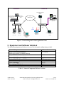
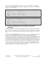
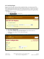
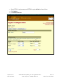
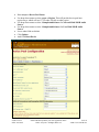
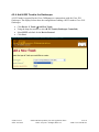
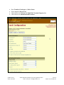
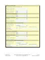
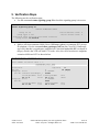
Avaya Solution & Interoperability Test Lab
Configuring Avaya Communication Manager, Cisco 2811
Gatekeeper and Cisco CallManager to Control VoIP Calls
between Avaya and Cisco Telephones - Issue 1.0
Abstract
These Application Notes describe a configuration, including, Avaya Communication Manager,
a Cisco 2811 Gatekeeper, and Cisco CallManager that was verified for a customer proof of
concept request. In this configuration, Avaya Communication Manager and Cisco
CallManager are registered with the Cisco 2811 Gatekeeper, which provides call control
between Avaya Communication Manager and Cisco CallManager.
SZ; Reviewed:
SPOC 8/10/2007
Solution & Interoperability Test Lab Application Notes
©2007 Avaya Inc. All Rights Reserved.
1 of 30
ACM-Cisco-CM-GK.doc
1. Introduction
An H.323 gatekeeper can provide address translation and network access control services for
H.323 terminals and gateways. These Application Notes present the configuration steps to allow
Avaya Communication Manager to communicate with Cisco CallManager via a Cisco 2811
Gatekeeper. These Application Notes will cover the necessary configuration steps for Avaya
Communication Manager, a Cisco 2811 Gatekeeper and Cisco CallManager.
Figure 1 depicts the network configuration utilized for these Application Notes.
In Location A in Figure 1, the Avaya G350 Media Gateway with S8300 Server provides both
H.323 Gateway (GW) and Gatekeeper (GK) functionality. In Location B, the Cisco 2811 access
router is configured as an H.323 Gatekeeper, and the Cisco CallManager is registered with it.
The Cisco 2811 GK provides E.164 to IP address resolution and call control for bandwidth
between the Location A and Location B.
The are two zones defined on this Gatekeeper, a local zone for Location B and a remote zone
for Location A. The Gatekeeper stays in Local zone. The following shows the basic flow for a
call from Location A to Location B:
• Avaya Communication Manager sends a Location Request (LRQ) message to the Cisco
2811 Gatekeeper.
• The Cisco 2811 Gatekeeper checks its dial plan and bandwidth requirement
• If the call meets the bandwidth requirement:
o The Cisco 2811 GK responds with location confirm (LCF) to Avaya
Communication Manager.
o Avaya Communication Manager will set up the call to the Cisco CallManager
through H.225 (Q.931) signaling.
• If the bandwidth requested exceeds the bandwidth requirement, the Cisco 2811
Gatekeeper sends call Location Rejection (LRJ) to Avaya Communication Manager to
deny the call.
Similarly, this call flow can be applied for call origination in Location B to Location A.
SZ; Reviewed:
SPOC 8/10/2007
Solution & Interoperability Test Lab Application Notes
©2007 Avaya Inc. All Rights Reserved.
2 of 30
ACM-Cisco-CM-GK.doc
Location A
Location B
Cisco 7960 IP Telephone
60.1.1.101
x61002
CISCO
796 IP
PHONE
0
Avaya S8300 Server with
G350 Media Gateway
IP: 22.1.1.22
Avaya 2420
Digital Telephone
x4501
1
2
3DE
AB
C
F
4
5
6N
GH
JK
M
I
L
O
7
8
9
PQR
TU
WXY
S
V
Z
#
0
OPE
R
messagdirectori
esi settin
es
servic
es
gs
*
MPLS WAN
T1
Cisco CallManager 4.1
60.1.1.5
T1
Ethernet
Ethernet
Cisco Catalyst
3750
Zone:
Remote
Zone:
Local
CISCO
796 IP
PHONE
0
Avaya 4600
IP Telephone
X4550
22.1.1.101
1
2B 3DE
A
C
F
4
5
6
GH
JK
MN
L
7I
9O
T8U WXY
PQR
V
S
Z
#
0
OPE
R
messagdirectori
esi setting
es
service
s
s
*
Avaya 9630
IP Telephone
X4555
22.1.1.100
Cisco 2811
GateKeeper
60.1.1.10
Cisco 7970 IP Telephone
60.1.1.100
x61000
DHCP/TFTP
Server
Figure 1: Network Diagram for these Application Notes
2. Equipment and Software Validated
The following equipment and software were used for the sample configuration provided:
Network Component
Avaya Communication Manager
S8300 Server with G350 Media Gateway
Avaya G350 Media Gateway
Software Version
3.1.2 (634)
Avaya 9600 IP Telephone (H.323)
Avaya 4620 IP Telephone (H.323)
Cisco 2811 Gatekeeper
Cisco CallManager
Cisco Catalyst 3750 Switch
Cisco 7970/7960 IP Telephones
1.2.1
2.7
12.4(2)T5 (IP Voice)
4.1(2)
8.2.1
7.2
26.31
Table 1 - Network Component Software Versions
SZ; Reviewed:
SPOC 8/10/2007
Solution & Interoperability Test Lab Application Notes
©2007 Avaya Inc. All Rights Reserved.
3 of 30
ACM-Cisco-CM-GK.doc
3. Avaya Communication Manager Configuration
3.1. Configuring Node Names on the Avaya Communication Manager
This section presents configuration steps for node name to IP address mapping on Avaya
Communication Manager. It is assumed that appropriate license and authentication files have
been installed on the S8300 Server. It is also assumed that the network IP address on the S8300
Server has been configured to 22.1.1.22/24 and the IP address on the G350 GW has been
configured to 22.1.1.23/24.
Avaya Communication Manager SAT screens can be accessed using “telnet 192.11.13.6 5023”
from a computer connected to the services port, or “telnet 22.1.1.22 5023” through the network.
Use the command change node-names ip to display the mapping of node names to IP addresses.
The node name Call-Manager is mapped to Cisco CallManager’s IP address 60.1.1.5 and the
node name Cisco-GK is mapped to the Cisco 2811 router’s IP address 60.1.1.10. The procr is
mapped to the Avaya S8300 Server’s IP Address 22.1.1.22.
change node-names ip
Name
Call-Manager
Cisco-GK
procr
Page
IP NODE NAMES
Name
IP Address
60 .1 .1 .5
60 .1 .1 .10
22 .1 .1 .22
1 of
1
IP Address
.
.
.
.
.
.
.
.
.
3.2. Configuring IP Network Region
In this sample configuration, the IP network region 1 is configured for Location A and the IP
network region 2 is configured for Location B.
Use the command change ip-network-region 1 to specify the IP codec set to be used for
network region 1 and the IP codec set used between network region 1 and region 2. Page 1 of 19
shows that codec set 1 is used for network region 1. The fields under DIFFSERV/TOS
PARAMETERS and 802.1P/Q PARAMETERS are used for QoS. The Avaya IP telephone
will receive these QoS parameters upon registration.
SZ; Reviewed:
SPOC 8/10/2007
Solution & Interoperability Test Lab Application Notes
©2007 Avaya Inc. All Rights Reserved.
4 of 30
ACM-Cisco-CM-GK.doc
change ip-network-region 1
Page
1 of
19
IP NETWORK REGION
Region: 1
Location:
Name:
Home Domain:
Intra-region IP-IP Direct Audio: no
Inter-region IP-IP Direct Audio: no
IP Audio Hairpinning? n
AUDIO PARAMETERS
Codec Set: 1
UDP Port Min: 16384
UDP Port Max: 32767
DIFFSERV/TOS PARAMETERS
Call Control PHB Value: 34
Audio PHB Value: 46
802.1P/Q PARAMETERS
Call Control 802.1p Priority: 3
Audio 802.1p Priority: 6
H.323 IP ENDPOINTS
H.323 Link Bounce Recovery? y
Idle Traffic Interval (sec): 20
Keep-Alive Interval (sec): 5
Keep-Alive Count: 5
RTCP Reporting Enabled? y
RTCP MONITOR SERVER PARAMETERS
Use Default Server Parameters? y
AUDIO RESOURCE RESERVATION PARAMETERS
RSVP Enabled? n
Page 3 of 19 shows that calls between network region 1 and 2 are allowed, up to the 256:Kbps.
Calls above the specified limit will not be permitted, and may be re-routed to a different path.
The bandwidth usage is based on the packet size and codec selection. Avaya supports IP Call
Admission Control via Bandwidth Limits (CAC-BL). Codec set 2 is used for calls between
regions 1 and 2.
change ip-network-region 1
Page
3 of
19
Inter Network Region Connection Management
src
rgn
1
1
dst codec direct
Total
rgn set
WAN WAN-BW-limits
1
1
2
2
y
256:Kbits
SZ; Reviewed:
SPOC 8/10/2007
Video
WAN-BW-limits
Intervening-regions
0:Kbits
Solution & Interoperability Test Lab Application Notes
©2007 Avaya Inc. All Rights Reserved.
Dyn
CAC IGAR
n
5 of 30
ACM-Cisco-CM-GK.doc
Use the command change ip-network-region 2 to specify the IP codec set to be used for
network region 2 and the IP codec set used between network region 1 and region 2. Page 1 of 19
shows that codec set 2 is used for network region 2.
change ip-network-region 2
Page
1 of
19
IP NETWORK REGION
Region: 2
Location:
Name:
Home Domain:
Intra-region IP-IP Direct Audio: no
Inter-region IP-IP Direct Audio: no
IP Audio Hairpinning? n
AUDIO PARAMETERS
Codec Set: 2
UDP Port Min: 16384
UDP Port Max: 32767
DIFFSERV/TOS PARAMETERS
Call Control PHB Value: 34
Audio PHB Value: 46
802.1P/Q PARAMETERS
Call Control 802.1p Priority: 3
Audio 802.1p Priority: 6
H.323 IP ENDPOINTS
H.323 Link Bounce Recovery? y
Idle Traffic Interval (sec): 20
Keep-Alive Interval (sec): 5
Keep-Alive Count: 5
RTCP Reporting Enabled? y
RTCP MONITOR SERVER PARAMETERS
Use Default Server Parameters? y
AUDIO RESOURCE RESERVATION PARAMETERS
RSVP Enabled? n
Page 3 of 19 shows that calls between network region 2 and 1 are allowed, up to the 256:Kbps.
Calls above the specified limit will not be permitted, and may be re-routed to a different path.
The bandwidth usage is based on the packet size and codec selection. Avaya supports IP Call
Admission Control via Bandwidth Limits (CAC-BL). Codec set 2 is used for calls between
regions 2 and 1.
change ip-network-region 2
Page
3 of
19
Inter Network Region Connection Management
src
rgn
2
2
dst codec direct
Total
rgn set
WAN WAN-BW-limits
1
2
y
256:Kbits
2
2
SZ; Reviewed:
SPOC 8/10/2007
Video
WAN-BW-limits
0:Kbits
Intervening-regions
Solution & Interoperability Test Lab Application Notes
©2007 Avaya Inc. All Rights Reserved.
Dyn
CAC IGAR
n
6 of 30
ACM-Cisco-CM-GK.doc
Use the command change ip-codec-set x (where x is the codec-set number) to configure IP
codec(s). The following screens show the codec configuration. IP-codec-set 1 uses G.711MU
and ip-codec-set 2 uses G.729.
change ip-codec-set 1
Page
1 of
1
Page
1 of
1
IP Codec Set
Codec Set: 1
Audio
Codec
1: G.711MU
2:
Silence
Suppression
n
Frames
Per Pkt
2
Packet
Size(ms)
20
change ip-codec-set 2
IP Codec Set
Codec Set: 2
Audio
Codec
1: G.729
2:
Silence
Frames
Packet
Suppression Per Pkt Size(ms)
n
2
20
3.3. Configuring Signaling and Trunk Groups to Cisco 2811
Gatekeeper
In order to configure Avaya Communication Manager as an H.323 Gatekeeper to send LRQ to
the Cisco 2811 GK, a signaling group for outbound traffic must be configured. Note that the IP
address of the Avaya S8300 Server (procr) functions as an IP address for both H.323 GW and
GK.
Use the command add signaling-group <group number> to create a signaling group. The NearEnd Node Name and Far-end Node Name are configured to the procr and Cisco-GK
respectively. To configure the Avaya S8300 Server as a H.323 GK, LRQ required must be set to
y. Near-end Listen Port and Far-end Listen Port must be configured to 1719 (UDP port 1719 for
H.225 RAS). Direct IP-IP Audio Connections and IP Audio Hairpinning must be set to n for
successful media paths. Disabling Direct IP-IP and IP Audio hairpinning will establish the RTP
stream between the G350 Media Gateway and the Cisco IP Telephones for inter location calls.
To support out-of-band DTMF, DTMF over IP must be configured to out-of-band. To control
Codec Set selection, the Far-end Network Region is configured to 2. Note that this signaling
group is configured to be associated with the trunk group 20.
SZ; Reviewed:
SPOC 8/10/2007
Solution & Interoperability Test Lab Application Notes
©2007 Avaya Inc. All Rights Reserved.
7 of 30
ACM-Cisco-CM-GK.doc
add signaling-group 20
Page
1 of
5
SIGNALING GROUP
Group Number: 20
Group Type:
Remote Office?
SBS?
IP Video?
Trunk Group for Channel Selection:
Supplementary Service Protocol:
T303 Timer(sec):
Near-end Node Name: procr
Near-end Listen Port: 1719
LRQ Required? y
RRQ Required? n
Media Encryption? n
DTMF over IP: out-of-band
h.323
n
n
n
20
a
10
Max number of NCA TSC: 20
Max number of CA TSC: 0
Trunk Group for NCA TSC:
Far-end Node Name: Cisco-GK
Far-end Listen Port: 1719
Far-end Network Region: 2
Calls Share IP Signaling Connection? n
H245 Control Addr On FACility? n
Bypass If IP Threshold Exceeded? n
H.235 Annex H Required? n
Direct IP-IP Audio Connections? n
IP Audio Hairpinning? n
Interworking Message: PROGress
DCP/Analog Bearer Capability: 3.1kHz
Use the command add trunk–group <group number> to add an IP trunk group. The following
screen shows the configuration of the IP trunk group 20. As a standard IP trunk configuration,
Group Type is configured to isdn, Carrier Medium to H.323 and Service Type to tie.
add trunk-group 20
Page
1 of
21
TRUNK GROUP
Group Number:
Group Name:
Direction:
Dial Access?
Queue Length:
Service Type:
20
TO Ciso-GK
two-way
n
0
tie
Group Type:
COR:
Outgoing Display?
Busy Threshold:
isdn
1
n
255
CDR Reports: y
TN: 1
TAC: 120
Carrier Medium: H.323
Night Service:
Auth Code? n
Member Assignment Method: manual
SZ; Reviewed:
SPOC 8/10/2007
Solution & Interoperability Test Lab Application Notes
©2007 Avaya Inc. All Rights Reserved.
8 of 30
ACM-Cisco-CM-GK.doc
Note that Codeset to Send Display must be configured to 0 in order for the Cisco GW to accept
the Q.931 call setup message from the Avaya Media Gateway.
add trunk-group 20
Group Type: isdn
Page
TRUNK PARAMETERS
Codeset to Send Display: 0
Supplementary Service Protocol: a
Incoming Calling Number - Delete:
2 of
21
Codeset to Send National IEs: 6
Charge Advice: none
Digit Handling (in/out): enbloc/enbloc
Insert:
QSIG Value-Added? n
Digital Loss Group: 18
Format: unk-pvt
In order to support caller ID on the IP trunk (isdn type), configure Send Name and Send Calling
Number to y. In the sample configuration, the Format is configured to unk-pvt.
add trunk-group 20
TRUNK FEATURES
ACA Assignment? n
Used for DCS? n
Suppress # Outpulsing? n
Send UUI IE? y
Send UCID? n
Send Codeset 6/7 LAI IE? y
SZ; Reviewed:
SPOC 8/10/2007
Page
Measured: none
Internal Alert? n
Data Restriction? n
Send Name: y
3 of
21
Maintenance Tests? y
NCA-TSC Trunk Member:
Send Calling Number: y
Send EMU Visitor CPN? n
Format: unk-pvt
UUI IE Treatment: service-provider
Replace Restricted Numbers?
Replace Unavailable Numbers?
Send Connected Number:
Hold/Unhold Notifications?
Modify Tandem Calling Number?
Solution & Interoperability Test Lab Application Notes
©2007 Avaya Inc. All Rights Reserved.
n
n
n
n
n
9 of 30
ACM-Cisco-CM-GK.doc
IP trunk member port values are initially configured to “ip” in the Port field. The system will
then assign a value to the port as shown below. Note the IP trunk members are virtual ports. In
the following screen, five members associated with signaling group 20 are configured. This
means that the IP trunk group only supports five simultaneous VoIP calls. The sixth call will be
blocked if there is no backup trunk available. If a PSTN trunk is configured as a backup trunk,
the additional calls can be overflowed to the PSTN, or all calls can use the PSTN if the VoIP
trunk is out of service.
display trunk-group 20
GROUP MEMBER ASSIGNMENTS
1:
2:
3:
4:
5:
6:
Port
T00086
T00087
T00088
T00089
T00090
Name
Page
5 of 21
TRUNK GROUP
Administered Members (min/max):
1/5
Total Administered Members:
5
Night
Sig Grp
20
20
20
20
20
When a call is placed from Avaya Communication Manager, the called number is routed (by
appropriate routing, e.g., UDP, AAR/ARS, etc.) to the Cisco 2811 Gatekeeper via trunk group
20. The Cisco 2811 Gatekeeper will send the call setup message to the appropriate gateway, for
these Application Notes, Cisco CallManager.
SZ; Reviewed:
SPOC 8/10/2007
Solution & Interoperability Test Lab Application Notes
©2007 Avaya Inc. All Rights Reserved.
10 of 30
ACM-Cisco-CM-GK.doc
Separate signaling and trunk groups are required for Avaya Communication Manager to receive
calls. When Avaya Communication Manager receives a call setup message from a Cisco
CallManager via the Cisco 2811 Gatekeeper, Avaya Communication Manager will try to match
it to a signaling group based on the remote GW’s IP address. The call will be denied if there is
no match. To reduce the configuration required, the Far-end Node Name can be left unspecified,
or an inbound signaling group can be configured for each GW from which Avaya
Communication Manager should accept calls. The following screen shows the configuration for
inbound signaling group 21. Note that Near-end Listen Port must be 1720 to accept incoming
calls (TCP port 1720 for H.225 call setup messages). The LRQ Required is set to n. Like the
configuration for signaling group 20, Direct IP-IP Audio Connections and IP Audio Hairpinning
are set to n, DTMF over IP is configured to out-of-band, and the Far-end Network Region is set
to 2.
display signaling-group 21
Page
1 of
5
SIGNALING GROUP
Group Number: 21
Group Type:
Remote Office?
SBS?
IP Video?
Trunk Group for Channel Selection:
Supplementary Service Protocol:
T303 Timer(sec):
Near-end Node Name: procr
Near-end Listen Port: 1720
LRQ Required? n
RRQ Required? n
Media Encryption? n
DTMF over IP: out-of-band
h.323
n
n
n
21
a
10
Max number of NCA TSC: 0
Max number of CA TSC: 0
Trunk Group for NCA TSC: 20
Far-end Node Name:
Far-end Listen Port:
Far-end Network Region: 2
Calls Share IP Signaling Connection? n
H245 Control Addr On FACility? n
Bypass If IP Threshold Exceeded? n
H.235 Annex H Required? n
Direct IP-IP Audio Connections? n
IP Audio Hairpinning? n
Interworking Message: PROGress
DCP/Analog Bearer Capability: 3.1kHz
The following screen captures show the configuration of an IP trunk group 21 for incoming calls
from Location B.
display trunk-group 21
Page
1 of
21
TRUNK GROUP
Group Number:
Group Name:
Direction:
Dial Access?
Queue Length:
Service Type:
SZ; Reviewed:
SPOC 8/10/2007
21
OUTSIDE CALL
two-way
n
0
tie
Group Type:
COR:
Outgoing Display?
Busy Threshold:
isdn
1
n
255
CDR Reports: y
TN: 1
TAC: 121
Carrier Medium: H.323
Night Service:
Auth Code? n
Member Assignment Method: manual
Solution & Interoperability Test Lab Application Notes
©2007 Avaya Inc. All Rights Reserved.
11 of 30
ACM-Cisco-CM-GK.doc
display trunk-group 21
Group Type: isdn
Page
TRUNK PARAMETERS
Codeset to Send Display: 0
Disconnect Supervision - In? y
Answer Supervision Timeout: 0
display trunk-group 21
TRUNK FEATURES
ACA Assignment? n
Used for DCS? n
Suppress # Outpulsing? n
GROUP MEMBER ASSIGNMENTS
1:
2:
3:
4:
5:
6:
Port
T00091
T00092
T00093
T00094
T00095
SZ; Reviewed:
SPOC 8/10/2007
Name
QSIG Value-Added? n
Digital Loss Group: 18
Format: unk-pvt
Insert:
Out? n
Page
Measured:
Internal Alert?
Data Restriction?
Send Name:
none
n
n
y
3 of
21
Maintenance Tests? y
NCA-TSC Trunk Member:
Send Calling Number: y
Send EMU Visitor CPN? n
Format: unk-pvt
UUI IE Treatment: service-provider
Replace Restricted Numbers?
Replace Unavailable Numbers?
Send Connected Number:
Hold/Unhold Notifications?
Modify Tandem Calling Number?
Send UUI IE? y
Send UCID? n
Send Codeset 6/7 LAI IE? y
display trunk-group 21
21
Codeset to Send National IEs: 6
Charge Advice: none
Digit Handling (in/out): enbloc/enbloc
Supplementary Service Protocol: a
Incoming Calling Number - Delete:
2 of
Page
TRUNK GROUP
Administered Members (min/max):
Total Administered Members:
Night
5 of
n
n
y
y
n
21
1/5
5
Sig Grp
21
21
21
21
21
Solution & Interoperability Test Lab Application Notes
©2007 Avaya Inc. All Rights Reserved.
12 of 30
ACM-Cisco-CM-GK.doc
3.4. Configuring Dial Plan and Caller ID on Avaya Communication
Manager
Uniform Dialing Plan (UDP) and Automated Alternate Routing (AAR) are used for the call
routing. The configurations in this section are for demonstration only.
Use the command display system-parameters customer-options to verify that Uniform Dialing
Plan is set to y.
display system-parameters customer-options
OPTIONAL FEATURES
Posted Messages? n
PNC Duplication? n
Port Network Support? y
Processor and System MSP? n
Private Networking? y
Page
5 of
10
Tenant Partitioning? n
Terminal Trans. Init. (TTI)? n
Time of Day Routing? n
Uniform Dialing Plan? y
Usage Allocation Enhancements? y
TN2501 VAL Maximum Capacity?
…
Use the command change dialplan analysis to configure the dial plan. The dialed digits 61xxx
(“x” is any digit) is configured as ext. Note the digits 61xxx match the extensions created on the
Cisco CallManager.
change dialplan analysis
Page
1 of
12
DIAL PLAN ANALYSIS TABLE
Percent Full: 1
Dialed
String
1
2
61
SZ; Reviewed:
SPOC 8/10/2007
Total
Length
3
4
5
Call
Type
dac
ext
ext
Dialed
String
Total Call
Length Type
Dialed
String
Solution & Interoperability Test Lab Application Notes
©2007 Avaya Inc. All Rights Reserved.
Total Call
Length Type
13 of 30
ACM-Cisco-CM-GK.doc
Use the command change aar analysis 6 (“6” is the first dialed digit) to configure the dialed
digits 61xxx to use aar and route pattern 20.
change aar analysis 6
Page
1 of
2
AAR DIGIT ANALYSIS TABLE
Percent Full:
Dialed
String
Total
Min Max
5
5
61
Route
Pattern
20
Call
Type
aar
Node
Num
1
ANI
Reqd
n
…
Use the command change route-pattern 20 to set the trunk group 20 as a primary trunk group to
carry the calls to 61xxx. Since there are no digits deleted or inserted, all 5 digits will be used as
the called number. The Numbering Format is configured to lev0-pvt to support caller ID in the
sample configuration.
change route-pattern 20
Pattern Number: 20 Pattern Name: cisco-GK
SCCAN? n
Secure SIP? n
Grp FRL NPA Pfx Hop Toll No. Inserted
No
Mrk Lmt List Del Digits
Dgts
1: 20
0
2:
3:
4:
5:
6:
BCC VALUE TSC CA-TSC
0 1 2 3 4 W
Request
1: y y y y y n
2: y y y y y n
3: y y y y y n
n
n
n
Page
1 of
3
DCS/
QSIG
Intw
n
n
n
n
n
n
IXC
user
user
user
user
user
user
ITC BCIE Service/Feature PARM
No. Numbering LAR
Dgts Format
Subaddress
lev0-pvt none
none
none
rest
rest
rest
In order to support caller ID for the private network, use the command display systemparameters customer-options to verify that Private Networking is set to y.
display system-parameters customer-options
OPTIONAL FEATURES
Posted Messages? n
PNC Duplication? n
Port Network Support? y
Processor and System MSP? n
Private Networking? y
Page
5 of
Tenant Partitioning?
Terminal Trans. Init. (TTI)?
Time of Day Routing?
Uniform Dialing Plan?
Usage Allocation Enhancements?
TN2501 VAL Maximum Capacity?
10
n
y
n
y
y
n
…
SZ; Reviewed:
SPOC 8/10/2007
Solution & Interoperability Test Lab Application Notes
©2007 Avaya Inc. All Rights Reserved.
14 of 30
ACM-Cisco-CM-GK.doc
Use the command change private-numbering to change private format for the calling number.
The configuration below will use the phone extension as the calling number.
change private-numbering
Page
1 of
1
NUMBERING - PRIVATE FORMAT
Network Level: 0
Level 2 Code:
Level 1 Code:
PBX Identifier:
Deleted Digits: 0
The command save translation must be entered to save the administration performed.
4. Cisco 2811 Gatekeeper and Cisco CallManager
Configuration
4.1. Configuring the Cisco 2811 Gatekeeper
The following are the annotated Cisco 2811 Gatekeeper configuration. A Gatekeeper will
forward the LRQ from Avaya CM and Cisco CallManager when the LRQ forwarding is enabled
on the GK. To enable a gatekeeper to forward LRQ messages, use the lrq forward-queries
command in gatekeeper configuration mode. Note that lrq forward-queries add-hop-count
must be configured on the Cisco 2811 GK, to allow the Cisco 2811 GK to forward the LRQ from
Avaya Communication Manager.
There is one local zone named GateKeeper and one remote zone named G350 configured on the
Cisco 2811 GK. Zone prefix “61*” (where * will match any sequence of numbers following 61)
is associated with the Cisco CallManager telephone extensions, and the Zone prefix “45*” is
associated with the extensions configured on Avaya Communication Manager.
For bandwidth control, the maximum bandwidth allowed between the local and remote zones is
configured as 256 kb. If the maximum bandwidth is fully utilized, the GK will reject any
additional call attempts.
SZ; Reviewed:
SPOC 8/10/2007
Solution & Interoperability Test Lab Application Notes
©2007 Avaya Inc. All Rights Reserved.
15 of 30
ACM-Cisco-CM-GK.doc
voice call carrier capacity active
!
interface FastEthernet0/0
ip address 60.1.1.10 255.255.255.0
duplex auto
speed auto
!
!
ip classless
ip route 0.0.0.0 0.0.0.0 60.1.1.2
Interface FastEthernet 0/0
configuration.
gatekeeper
zone local GateKeeper ABC.com 60.1.1.10
Enter Gatekeeper configuration
Configure local zone GateKeeper
with IP address 60.1.1.10.
zone remote G350 ABC.com 22.1.1.22 1719
Configure remote zone G350 with
IP address 22.1.1.22.
Configure zone prefix for remote
GK G350. Gatekeeper will route
calls starting with digits 45 to
G350 Media Gateway.
zone prefix G350 45*
zone prefix GateKeeper 61*
Configure Cisco CallManager
prefix to 61*. Gatekeeper will
route calls starting with digits
61 to Cisco CallManager.
gw-type-prefix 1#* default-technology gw
ipaddr 60.1.1.5 1720
Configure 1#* as defaulttechnology for Cisco CallManager.
lrq forward-queries add-hop-count
Enable lrq forward
bandwidth remote 256
bandwidth check-destination
no shutdown
SZ; Reviewed:
SPOC 8/10/2007
Configure the Max. bandwidth to
remote zone 256kb.
Enable bandwidth checking before
permit call.
Enable Gatekeeper
Solution & Interoperability Test Lab Application Notes
©2007 Avaya Inc. All Rights Reserved.
16 of 30
ACM-Cisco-CM-GK.doc
4.2. Configuring Cisco CallManager
To use the Gatekeeper to control calls from the Cisco CallManager, the Cisco 2811 router must
be added on the Cisco CallManager as a Gatekeeper. Configurations are shown below.
4.2.1. Add Gatekeeper
Launch Cisco CallManager Administration Application and log in with proper user name and
password. The display below shows the gatekeeper configuration. To add a gatekeeper, follow
the following steps.
•
•
•
•
•
•
•
Click Device Æ Gatekeeper
Enter the Cisco 2811 Gatekeeper’s IP address 60.1.1.10 as Host Name/IP Address
Enter Gatekeeper for Description (Optional)
Leave Registration Request Time To Live and Registration Retry Timeout as default
Check box Enable Device
Click Update
Click Reset Gatekeeper
SZ; Reviewed:
SPOC 8/10/2007
Solution & Interoperability Test Lab Application Notes
©2007 Avaya Inc. All Rights Reserved.
17 of 30
ACM-Cisco-CM-GK.doc
4.2.2. Add New Region
Regions are used for codec selection. In these Application Notes, two regions are used. The
default region is used for Location B and a new region, named Avaya, is created for Location A.
To save bandwidth on WAN link, codec G.729 is used between these two regions. Intra-region
calls will use codec G.711 ulaw. The following steps show how to create a new region on Cisco
CallManager.
• Click System Æ Region
• Click Add a New Region as shown below
•
•
•
Enter avaya as Region Name
Select G.729 as Default Codec with Other Regions. This will force the Cisco
CallManager to use codec G.729 for calls to other region.
Click Insert
SZ; Reviewed:
SPOC 8/10/2007
Solution & Interoperability Test Lab Application Notes
©2007 Avaya Inc. All Rights Reserved.
18 of 30
ACM-Cisco-CM-GK.doc
•
•
•
Click System Æ Region
Click Find and two regions are displayed
Click the Region for avaya
SZ; Reviewed:
SPOC 8/10/2007
Solution & Interoperability Test Lab Application Notes
©2007 Avaya Inc. All Rights Reserved.
19 of 30
ACM-Cisco-CM-GK.doc
•
•
•
Select G.711 for region avaya and G.729 for region default as shown below
Click Update
Click Restart Devices
SZ; Reviewed:
SPOC 8/10/2007
Solution & Interoperability Test Lab Application Notes
©2007 Avaya Inc. All Rights Reserved.
20 of 30
ACM-Cisco-CM-GK.doc
4.2.3. Add a New Device Pool
There is a default device pool pre-defined on the Cisco CallManager. In these Application Notes,
the Cisco CallManager will use this default device pool. A new device pool, named avaya, will
be created for Avaya S8300 Server with G350 Media Gateway in Location A. The purpose of
creating a new device pool is to use different regions defined in previous section to select
different codec. The display below shows the device pool configuration utilized for these
Application Notes. Follow the following steps to add a new device pool to the Cisco
CallManager database.
• Click System Æ Device Pool
• Click link Add a New Device Pool
SZ; Reviewed:
SPOC 8/10/2007
Solution & Interoperability Test Lab Application Notes
©2007 Avaya Inc. All Rights Reserved.
21 of 30
ACM-Cisco-CM-GK.doc
•
•
•
•
•
•
•
Enter avaya as Device Pool Name.
Use drop-down menu to select avaya as Region. This will put this device pool into
region avaya, which will use G.729 codec for calls to other region.
Use drop-down menu to select 1-SampleAudioSource for Network Hold MOH Audio
Source.
Use drop-down menu to select 1-SampleAudioSource for User Hold MOH Audio
Source.
Leave other fields as default.
Click Update
And Click Reset Device
SZ; Reviewed:
SPOC 8/10/2007
Solution & Interoperability Test Lab Application Notes
©2007 Avaya Inc. All Rights Reserved.
22 of 30
ACM-Cisco-CM-GK.doc
4.2.4. Add H.225 Trunk to the Gatekeeper
A H.225 trunk is required for the Cisco CallManager to communicate with the Cisco 2811
Gatekeeper. The displays below show the configuration of adding a H.225 trunk to Cisco 2811
Gatekeeper.
•
•
•
•
Click Device Æ Trunk Æ Add New Trunk
Using the drop-down menu to select H.225 Trunk (Gatekeeper Controlled)
Select H.255 as default for the Device Protocol
Click Next
SZ; Reviewed:
SPOC 8/10/2007
Solution & Interoperability Test Lab Application Notes
©2007 Avaya Inc. All Rights Reserved.
23 of 30
ACM-Cisco-CM-GK.doc
•
•
•
•
Enter Trunk-to-Gatekeeper as Device Name
Select avaya for Device Pool
Check the box for Wait for Far End H.245 Terminal Capacity Set
Check the box for Enable Inbound FastStart
SZ; Reviewed:
SPOC 8/10/2007
Solution & Interoperability Test Lab Application Notes
©2007 Avaya Inc. All Rights Reserved.
24 of 30
ACM-Cisco-CM-GK.doc
•
•
•
•
•
•
Using the drop-down menu to select Gatekeeper IP address 60.1.1.10 for Gatekeeper
Name
Using the drop-down menu to select Gateway for Terminal Type
Enter 1#* as Technology Prefix to match the gateway prefix configured on Cisco 2811
Gatekeeper.
Leave other fields as default
Click Update
Click Reset Trunk
SZ; Reviewed:
SPOC 8/10/2007
Solution & Interoperability Test Lab Application Notes
©2007 Avaya Inc. All Rights Reserved.
25 of 30
ACM-Cisco-CM-GK.doc
4.2.5. Configure a Route Pattern
Extension range 45xx is assigned to users at Location A. When users dial 45xx from the
Location B, the Cisco CallManager knows how to route the calls to the Gatekeeper using the
route pattern configured below. The call setup message will be carried out via the trunk selected
in this route pattern. The display below shows the route pattern configuration utilized for these
Application Notes. Follow the following steps to add a route pattern.
• Click Route Plan Æ Route/Hunt Æ Route Pattern Æ Add a New Route Pattern
• Enter 45XX for Route Pattern
• Using drop-down menu to select North American Numbering Plan for Numbering
Plan
• Using drop-down menu to select Trunk-to-Gatekeeper for Gateway or Route List
• Select the radio button for Route this pattern
• Leave remaining parameters as default setting
• Click Update
SZ; Reviewed:
SPOC 8/10/2007
Solution & Interoperability Test Lab Application Notes
©2007 Avaya Inc. All Rights Reserved.
26 of 30
ACM-Cisco-CM-GK.doc
SZ; Reviewed:
SPOC 8/10/2007
Solution & Interoperability Test Lab Application Notes
©2007 Avaya Inc. All Rights Reserved.
27 of 30
ACM-Cisco-CM-GK.doc
5. Verification Steps
The following are the verification steps:
• Use the commands status signaling-group 20 to check the signaling group is in service.
status signaling-group 20
STATUS SIGNALING GROUP
Group ID:
Group Type:
Signaling Type:
Group State:
•
20
h.323
facility associated signaling
in-service
Active NCA-TSC Count: 0
Active CA-TSC Count: 0
Make a call from extension 61000 (Cisco CallManager phone) to extension 4555 (Avaya
IP telephone). Use the command show gatekeeper call from the Cisco 2811 Gatekeeper
and verify that this is a gatekeeper controlled call. Note that bandwidth (BW) is shown 16
(Kbps), which is the VoIP call with G.729 codec. Also, the call is between two endpoints
extension 61000 and 4555 as shown below.
GateKeeper#show gatekeeper call
Total number of active calls = 1.
GATEKEEPER CALL INFO
====================
LocalCallID
Age(secs)
BW
542-195
6
16 (Kbps)
Endpt(s): Alias
E.164Addr
src EP: Trunk-to-Gatekeeper_1
61000
CallSignalAddr Port R ASSignalAddr
Port
60.1.1.5
54155
60.1.1.5
59507
Endpt(s): Alias
E.164Addr
dst EP:
4555
CallSignalAddr Port
RASSignalAddr
Port
22.1.1.22
1720
22.1.1.22
1719
SZ; Reviewed:
SPOC 8/10/2007
Solution & Interoperability Test Lab Application Notes
©2007 Avaya Inc. All Rights Reserved.
28 of 30
ACM-Cisco-CM-GK.doc
•
Use the command status station 4555 from the SAT interface on Avaya Communication
Manager to check the status of this Avaya IP telephone. As shown from page 4 below,
this is a call using codec G.711MU from extension 4555 to S8300 Media Gateway VoIP
engine (22.1.1.1) and the connection-type is ip-tdm.
status station 4555
Page
AUDIO CHANNEL
Port: S00001
IP
Other-end IP Addr :Port
22. 1. 1. 1
:2050
Switch
Port
G.711MU
Audio: 1
Node Name:
Network Region:
1
Audio Connection Type: ip-tdm
Product ID and Release:
H.245 Tunneled in Q.931?
Registration Status:
MAC Address:
Native NAT Address:
ALG - NAT WAN IP address:
Authentication Type:
•
Port: S00001
IP_Phone
1.500
does not apply
registered-authenticated
00:04:0d:ec:06:c6
not applicable
not applicable
DES-56-plus
4 of
7
IP
Set-end IP Addr:Port
22. 1. 1.222:61974
1
Shared Port:
Page 6 shows the same call from S8300 Server VoIP engine (22.1.1.1) to a Cisco phone
(60.1.1.100) using codec g729.
status station 4555
Page
6 of
7
SRC PORT TO DEST PORT TALKPATH
src port: S00001
S00001:TX:22.1.1.222:61974/g711u/20ms
001V038:RX:22.1.1.1:2050/g711u/20ms
TX:ctxID:292
001V037:RX:ctxID:292
TX:22.1.1.1:2052/g729/20ms
T00091:RX:60.1.1.100:24204/g729/20ms
•
•
Change bandwidth to 16 kbs on Gatekeeper for remote zone (Location A). Place two
calls from Cisco CallManager to Location A and verify the fist call is successful and the
second call was rejected by gatekeeper because no more bandwidth available.
Verify that caller ID (calling name and number) can be displayed correctly.
6. Conclusion
As illustrated in these Application Notes, calls can be made between Avaya Communication
Manager and Cisco CallManager via a Cisco 2811 Gatekeeper.
SZ; Reviewed:
SPOC 8/10/2007
Solution & Interoperability Test Lab Application Notes
©2007 Avaya Inc. All Rights Reserved.
29 of 30
ACM-Cisco-CM-GK.doc
©2007 Avaya Inc. All Rights Reserved.
Avaya and the Avaya Logo are trademarks of Avaya Inc. All trademarks identified by ® and ™
are registered trademarks or trademarks, respectively, of Avaya Inc. All other trademarks are the
property of their respective owners. The information provided in these Application Notes is
subject to change without notice. The configurations, technical data, and recommendations
provided in these Application Notes are believed to be accurate and dependable, but are
presented without express or implied warranty. Users are responsible for their application of any
products specified in these Application Notes.
Please e-mail any questions or comments pertaining to these Application Notes along with the
full title name and filename, located in the lower right corner, directly to the Avaya Solution &
Interoperability Test Lab at [email protected]
SZ; Reviewed:
SPOC 8/10/2007
Solution & Interoperability Test Lab Application Notes
©2007 Avaya Inc. All Rights Reserved.
30 of 30
ACM-Cisco-CM-GK.doc