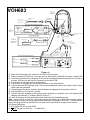
1
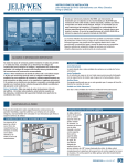
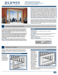
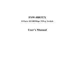
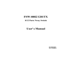
®
ELECTRONICS CORP.
VOH683 Drop Down Video Monitor
VOH684 Drop Down TV / Video Monitor
VOH704 Drop Down TV / Video Monitor
Installation Guide
F o r C ustom er S ervice
V is it O u r W e b site A t
WWW.audiovox.com
P ro du ct Info rm atio n , P h oto s,
FA Q ’s O w ner ’s M a nu als
Important Notice
It is unlawful in most jurisdictions for a person
to drive a motor vehicle which is equipped
with a television viewer or screen that is
located in the motor vehicle at any point
forward of the back of the driver's seat, or
that is visible directly or indirectly to the
operator of the motor vehicle.
Please note that the state of Rhode Island
forbids the installation of such a device in a
motor vehicle.
MATERIALS INCLUDED IN THIS PACKAGE:
1)
2)
3)
4)
5)
6)
7)
8)
9)
10)
11)
VOH683 Video Monitor with out TV Tuner / VOH684 or VOH704 Video Monitor with TV Tuner (1 pc)
Accessory Harness (P/N 8010730) (1 pc)
12 Pin Power / Signal harness (P/N 112B2821) (1 pc)
2 Pin Power Wire Harness with choke (P/N 112B2824) (1 pc)
Hardware Package
#4 x 1/4” Screws (5 pcs)
#8 x 5/8” Self Drilling Screws (4 pcs)
#8 Washers (4 pcs)
Remote Control (P/N 136B2063) (1pc)
Left Protective Cover for IR sensor (P/N 102B3596) (1pc)
Right Protective Cover for Headphone Jacks (P/N 102B3597) (1pc)
Mini Console (P/N 102D3595) (1pc)
Universal Antenna "Y" Adapter Cable (Female to Two Male) (P/N 112-3100) (1pc)
Universal Antenna Extension Cable (144"/366cm) (P/N 112-3099) (1pc)
3
1
3a
4
3
CHOKE
2
3a
9
3a
6
3
5
3a
7
3a
8
10
11
3c
TV POW ER
3e
MU TE
T V/VIDEO
1
2
3
4
5
6
CH
CH
7
8
9
VOL
0
1--
PICTURE
SELECT
VOL
SKIP/SEARCH
ERASE/
WRITE
RADIO POWER
MUTE
VCP POWER RECALL
REW
AUTO
MEMORY
TUNING
VOLUME
F.FWD
MEMORY
PLAY
REPLAY
STOP
®
TOOLS REQUIRED:
#2 Phillips Screwdriver
#1 Phillips Screwdriver
Utility or Razor Knife or Shears
Wire Strippers
Upholstery hook tool (for removal of panels as necessary)
Electrical Tape
Masking Tape
Multimeter (to verify 12 volt DC and continuity: Do not use a test light or logic probe)
Marker pen – to mark headliner
Scribe (to mark trim ring if used)
Misc. electrical connectors (to connect to vehicle power source). Requirements will vary from vehicle to
vehicle)
Video tape (to verify system operation after installation)
-1-
GENERAL INSTALLATION APPROACH:
1) Decide upon system configuration and options that will be installed (i.e.: what components, VCP,
Tuner, RF Modulator/external amp, remote headphones, 2nd VCP, etc.).
2) Review all manuals to become familiar with electrical requirements and hook ups.
3) Decide upon mounting locations of all components and method of mounting.
4) Prep the vehicle by removing any interior trim necessary to gain access to vehicle's wiring as well as
all areas where interconnecting wire harnesses will need to be located. If any access holes need to
be cut into the vehicle (headliner, other trim components etc.), this should be done now as well.
(Refer to Page 3).
5) Route the wiring harnesses throughout the vehicle as necessary. (Refer to the Wiring Diagrams on
pages 6 and 7 of this manual as well as the wiring instructions for the individual components and
accessory options being installed). Be sure that all wiring is protected from sharp edges and is routed
in such a manner that it will not be pinched when all components and interior trim are fully installed. Be
sure to leave enough slack in the wiring at each component to allow working room.
6) Remove all A/V system components from their packaging and place them loosely in the vehicle at
their respective locations.
7) Connect all components together (electrically) and verify proper operation of all system functions.
Note: This is best done BEFORE, components have been permanently mounted.
8) After verifying proper operation of the system, proceed to mount of each component.
9) When all components are mounted, recheck function of entire system again to ensure that no wiring
was pinched or connected improperly during final installation.
GENERAL SYSTEM CONFIGURATIONS:
The following is intended to provide some of the system configurations that are possible with the VOH683,
VOH 684 and VOH704 series Drop Down Video Systems:
System 1: Video Monitor without TV tuner (VOH683), with VCP and FM radio.
-All wiring necessary is included with this package.
-Headphones are connected into the headphone jacks on the monitor itself.
System 2: Video Monitor with TV tuner (VOH684 and VOH704), with VCP and FM radio.
-Same as system 1, but TV and FM radio antenna must be added (AN-300 or similar).
System 3: Video Monitor (VOH683), VCP, 2nd VCP (or other A/V component)
-Same as system 1 but extra Source Component (PN 8010730) Harness must be
purchased.
System 4: Video Monitor / TV (VOH684 and VOH704), VCP, 2nd VCP (or other A/V component)
-Same as system 3, but TV antenna must be added (AN-300 or similar).
Notes:
There are a few audio output options that can be added as follows:
a) Remote headphone jacks can be added to a VOH683 system. Refer to the wiring
diagram on page 6.
b) Additional speakers can be added to a VOH684 and VOH704 system using the
speaker outputs. Refer to the wiring diagram on page 7.
The VOH683, VOH 684 and VOH704 video systems are only intended for an overhead,
drop down installation. It is not intended for seat back or any other type of mounting. The
hinging mechanism is designed for horizontal, drop down use only.
-2-
VEHICLE PREPARATION:
1)
2)
3)
4)
Locate a constant power source (+12v at all times) and an accessory power source (+12v when
key is in the ACC. and run positions, and 0v when key is off). Generally, these wires can be found
at the ignition switch or fuse-box.
The mounting method and location will vary from vehicle to vehicle, so this manual will only focus
on the installation of the video monitor and related console accessories.
Generally, the best location for the video monitor is where the vehicle's factory dome light is installed. The monitor should be located in such a manner that it can be comfortably viewed by rear
seat passengers. NEVER INSTALL THE MONITOR IN A PLACE WITHIN THE DRIVER'S VIEW.
THIS IS NOT ONLY DANGEROUS, BUT IT IS ALSO ILLEGAL IN MANY STATES.
Once the mounting location of the monitor has been determined, there may be additional preparation work necessary, depending on the vehicle structure and installation method. Some of the
steps that may be required are:
A) Removal of the vehicle's dome light
B) The headliner may need to be trimmed as per the drawing below.
C) If the mini-console (P/N 102D3595) will be used, it will have to be trimmed to fit the
contour of the vehicle's headliner. Refer to the "Mini-Console installation" section late in
this manual.
Note:
If your installation will require you to cut out the headliner, the box that this kit came in can be used as a
template. You can remove the shelf that the video monitor rests on and trace the opening onto the
headliner for cutting
FULL SIZE CONSOLE INSTALLATION
There are several “full size” custom consoles available for selected vehicles. Some of these vehicles are
the Chevrolet Suburban, Ford Expedition, and Dodge Durango. These full size consoles incorporate
several additional features, and are particularly useful if the vehicle you are installing this system into
already has an OEM overhead console in the headliner.
Refer to the installation manual that comes with the console itself for complete installation instructions.
-3-
MINI CONSOLE INSTALLATION:
This page only covers special installation considerations for the mini-console installation. If the video
monitor is to be installed with a custom full sized overhead console, refer to page 3.
If the video monitor is to be installed in a vehicle with the mini console (P/N 102D3595), this console may
need to be trimmed to fit the contour of the vehicle headliner.
1)
2)
3)
4)
5)
In this installation, the video monitor is mounted directly to the overhead cross-member in the roof
using the mounting screw bosses. These screw bosses should contact the cross-member directly (i.e.: no gap between the screw boss and the roof structure). Also, be sure that the screws
do not pierce the outer roof skin when fully fastened to the cross-member. The mini-console is
attached to the video monitor using the perimeter screw bosses. It is important that the screws
used in this installation are not overtightened, and that the video monitor and mini-console are
mounted in such a way that the assembly does not distort (or bend) when the mounting screws
are tightened. An alternate method is to use a piece of plywood (5"x9"x3/4"). First secure the
plywood block to the cross-member, then screw the monitor into the plywood. See the drawing on
page 5.
It is best to mount the video monitor to the roof structure without the mini-console first. There
should be a gap between the headliner and the outer flange of the video monitor. The mini-console
should be cut to full this gap. Apply masking tape to the outer surface of the mini-console in the
areas where the cut will be made.
Mark the cut to follow the necessary contour of the roof. The suggested method of marking is as
follows:
A)
First mark the narrowest point of the mini-console on the masking tape. Be careful
to consider not only vertical location, but fore-aft location.
B)
Using the handle of a screwdriver, make a “transfer marking tool”. See diagram
below. Place the tool against the roof and the marker against the masking tape on
the mini-console. Trace the cut to be made around the entire perimeter of the miniconsole.
C)
Cut the mini-console using a sharp utility knife or shears. Make the cut in several
passes over the marked line, each time cutting a little deeper. It is not necessary to
cut completely through the plastic, the cut only need be over 50% of the wall thickness of the plastic. By bending the cut back and forth several times, the plastic will
break cleanly at the cut.
D)
Check the fit of the trimmed console and make any minor adjustments necessary.
The mini-console can be painted or covered with a material that matches the headliner before
assembling the mini-console to video monitor.
The finished mini-console should be attached to the video monitor, then attach the assembly to the
roof.
Headliner
Headliner
Cut line
Cut Line
Lowest Point Mark
Lowest point mark
Figure 6
Tape marker to screwdriver starting at
your mark for the lowest point, then
trace the contour of the roof
Refer to Fig 7 for detail on attaching
consoleat
to your
video pod
and video pod to
Tape marker to screwdriver. Starting
mark
vehicle structure.
for the lowest point, trace the contour
of the roof
-4-
MOUNTING THE MINI-CONSOLE
Roof
Roof Support
Headliner
5"x9"x3/4" Plywood
Block or Optional
VOHBKT
(4) #8x1" self drilling
screws (not supplied)
Mini-Console
Video Unit
(4) #8 flat washers
(not supplied)
(4) #8x3/4" self tapping
screws (not supplied)
-5-
VOH683
Note: cables
exiting the pod
should be routed
as shown.
12 Pin Power signal
Harness Item #3
Po w er H a rn e ss
It em # 4
R e d : + 1 2 VD C
(A cce s so ry C ir. )
Mini-Din Connectors
c h ok e
Bla c k: G r ou n d
Optional Hard W ired FM Modulator Output
2
12 VDC Power and Ground
TO
FAC TO RY
R A D IO
A m /F m
A nte n n a
D as h R a dio
FM
M o d u la to r
1 07 0 6 1 0
Patch Cord
RCA Male to Male
Right
*Refer to Instr uctions with the RF In put
Modulator K it for further details.
L EF T
W HIT E
RIGHT
R ED
RCA -Fem ale
Connect to FM radio antenna
or equiv alent.
To S econdary AV Monitor
TO
O P T IO N A L
A D D IT IO N A L
M O IN TO R
12 VDC Power and Ground
IN PUT
VIDEO
A ux illa ry
vide o d is pla y
1
RCA -Fem ale
Left
In put
Ac cess ory
Harnes s
Item # 2
Ac cess ory
Harnes s
Item # 2
RCA -Fem ale
Patch Cord
RCA M ale to Male
LINE
O UT
VIDEO
Red RCA (Audio Right)
W hite RCA (Audio Left)
Yellow R CA (Video)
Power Connector
4 Pin
IR LED :
Clean the IR R eceiver W indow on the front of the V CP.
Rem ove A dhesive Backing and A pply IR LED to IR
W indow on the Fac e of the V CP.
Optional Remote H eadphone S tations
Ste re o
H e a d ph o n e J ac k
G reen
(Right+)
Ste re o
H e a d ph o n e J ac k
Black
(G round)
"Y " Adapter
fo r use with
Non-S tereo
In stallations
Item# 5
G ray
(Left+ )
Figure A
1) Make the connections to the vehicle for the 12 pin wiring harness.
2) Remove screws on PCB Cover. Open the cover to gain access to Mini-Din Connector on main PCB.
3) Insert the Circular Mini-Din Connector of the source component harness through the wire tie loop on
the main PCB and into the Mini-Din Connector on the main PCB.
4) Pull the wire tie loop tight and cut off the excess.
5) Connect the 12 pin harness to the mating connector on the Video Monitor.
6) Connect the wired RF Modulator and / or the remote headphone jacks to the video monitor if those
options are being included.
7) Connect power harness to vehicle’s electrical system by tapping into an accessory hot line.
8) Reinstall PCB cover using the 2 screws.
9) Connect FM radio antenna to the existing vehicle antenna or equivalent using the supplied 144"
Adapter Cable and the "Y" Adapter (Refer to Figure C.)
10) Verify all functions of the System before final mounting of the finished assembly.
Note: A second VCP or other A/V Component can be connected to the video monitor system using a
second source component harness (purchased separately, part number: 8010730). This second harness would plug into the second Mini-Din connector on the main PCB as in steps 2 and 3 above.
A/V Source Definitions:
1= VCP (Right Mini-Din on main PCB)
2= 2nd VCP (or game or DVD, etc.…. left Mini-Din)
-6-
VOH684/VOH704
N ote: cables
ex iting the pod
s hould be routed
as sho w n.
12 Pin Power signal
R e d: + 1 2 V D C
(A ccess o r y C ir.)
P o w e r H a rn e s s
Item # 4
Mini-D in C onnec tors
c ho ke
B la ck: G ro un d
O ption al Hard Wired F M M od ulato r O utpu t
2
12 V DC Powe r an d Groun d
TO
FACTORY
RADIO
Am/Fm
Antenn a
Dash Radio
Left
Inpu t
FM
Modulator
1070610
1
R CA-Fem ale
Pa tch C o rd
R C A Ma le to Male
R ig ht
*R ef er t o Ins truc tions with the R F
Inpu t
Mod ulato r K it fo r fu rthe r d etails.
TV an tenna
(If applic able)
LE FT
WH I TE
R IG HT
R ED
R CA-Fem ale
Connect to FM radio antenna
or equivalent.
To Seco nd ary AV M on ito r
TO
OPTIONAL
ADDITIONAL
MOINTOR
12 V DC Powe r an d Groun d
Ac ce ss ory
H arnes s
Item # 2
R CA-Fem ale
IN PU T
VID E O
Auxillary
video displa y
Pa tch C o rd
R C A Ma le to Male
Ac ce ss ory
H arnes s
Item # 2
LIN E
O UT
VID E O
R ed RC A (Audio Rig ht)
Wh ite R C A (Audio Left)
Ye llo w RC A (Vid eo)
P ower Connecto r
4 Pin
IR LE D :
C le an the I R R eceive r W ind ow on the fro nt of the VCP.
R emo ve A dhes iv e Bac k ing a nd App ly IR LED t o IR
Window o n the Fac e of th e VC P.
O ption al External S peakers
"Y" A dapter
for us e w ith
N on-Ste reo
Ins tallations
Item # 5
G ree n
(R ight +)
Blac k
(Ground )
G ray
(Left+ )
Figure B
1) Make the connections to the vehicle for the 12 pin wiring harness.
2) Remove screws on PCB Cover. Open the cover to gain access to Mini-Din Connector on main
PCB. (Cover will remain attached to rivet hole).
3) Insert the Circular Mini-Din Connector of the source Component Harness through the wire tie loop
on the main PCB and into the Mini-Din Connector on the main PCB.
4) Pull the wire tie loop tight and cut off the excess.
5) Connect the Power Harness to the mating connector on the Video Monitor.
6) Connect the wired RF Modulator and / or the remote headphone jacks to the video monitor if those
options are being included.
7) Connect power harness to vehicle’s electrical system by tapping into an accessory hot line.
8) Reinstall PCB cover using the 2 screws.
9) Mount and connect the Television antenna.
10) Connect the FM radio antenna using the supplied 144" Adapter Cable and the "Y" Adapter (Refer to
Figure D.)
11) Verify all functions of the System before final mounting of the finished assembly.
Note: A second VCP or other A/V Component can be connected to the video monitor system using a
second Source Component Harness (purchased separately, part number: 8010730). This second
harness would plug into the second Mini-Din connector on the main PCB as in steps 2 and 3 above.
A/V Source Definitions:
1= TV Tuner
2= VCP (right Mini-Din on main PCB)
3= 2nd VCP (or game or future DVD, etc.…. left Mini-Din)
-7-
NOTE: The TV Atenna
is not used on VOH683
Figure C.
NOTE: The TV Atenna
is not used on VOH683
Figure D.
-8-
CONNECTING THE DOME LIGHTS
The dome lights in the video monitor require three connections to the vehicle's wiring. There are two
common types of dome light circuits used, positive or negative switched. Positive systems supply voltage to the interior lights to turn them on, negative switched systems apply ground to illuminate the bulbs.
To determine which system you have you must locate the wires at the dome light. On a positive switched
system, with all the doors closed and the lights out, both wires at the dome light will rest at ground. When
the light is activated, one of these wires will switch to +12 vdc. This is the vehicle's switching wire. On a
negative switched system, with all the doors closed and the lights out, both wires at the dome light will
rest at + 12vdc. When the light is activated, one of these wires will switch to ground. This is the switching
wire.
For positive systems, connect the purple / brown (Lamp auto) wire to the vehicle's switched wire. Then
connect the red / black (lamp on) wire to a fused constant 12 volt source and the black / red (lamp
common) wire to a good ground. Positive systems are commonly found on Ford vehicles.
For negative systems, connect the purple / brown (Lamp auto) wire to the vehicle's switched wire. Then
connect the red / black (lamp on) wire to a good ground and the black / red (lamp common) wire to fused
constant 12 volt source. Negative systems are commonly found on General Motors and import vehicles.
Note:
Some vehicles which incorporate transistorized control of the dome light circuit, such as the 1999 Dodge
Caravan, may require that the purple / brown (Lamp auto) wire be connected to the door pin switch wire,
as the additional current draw of the Monitor's lights may not be supported by the output of the vehicles
body control computer.
Positive Switched Dome lighting
To 12 pin
connector
on Monitor
Red / black - Lamp on
Black / red - Lamp common
Purple / brown - Lamp Auto
Factory Dome light circuit
To
constant
+12vdc
Factory Door ajar
switch or Body
Control computer
-9-
To
constant
+12vdc
Negative Switched Dome lighting
To 12 pin
connector
Red / black - Lamp on
Black / red - Lamp common
Purple / brown - Lamp Auto
To
constant
Factory Dome light circuit
To
constant
Factory Door ajar
switch or Body
Troubleshooting:
SYMPTOM:
REMEDY:
No power at Video Monitor
-Verify +12 VDC on Red wire at 2 pin Power Harness behind video monitor.
Verify ground connection with continuity test from known good ground to
black wire at 2 pin Power Harness
Power but no video or
sound
-Verify that the correct source is selected (i.e.: 1,2,3 or 4). Verify that the
source is on and playing a known good media (such as a videotape). Verify
connections at both ends of the source component harness.
Picture, but no sound
-Push and hold the volume up button until sound is heard over headphones.
If problem is limited to the dash radio, verify radio is tuned to the correct
channel, and that power to the wired RF modulator is on. (Refer to instructions with modulator kit). Otherwise, verify all connections per the wiring
diagram on pages 5, 6 and 7.
Static on TV Stations
(Tuner Version Only)
-Press Auto Program button. Then press CH up or CH down. Verify antenna mounting and connections to the tuner.
Note: Due to the nature of TV signals, vehicle motion, direction the vehicle
is facing, distance from the transmitter, nearby surroundings and weather
may adversely affect TV reception. These conditions may result in the
following: picture roll, "snowy" picture, or momentary loss of color.
No FM Radio Stations
-Check and verify FM radio antenna mounting and connection. Verify that
the FM radio power is on and the front LCD display window is lit. Verify the
headphone set insert into the to jack.
No Infrared remote functions for VCP (or other components)
-Check batteries in the hand held remote (not included with this kit). Verify
that the IR LED ( page 6 or page 7 Wiring Diagram) is property attached to
the sensor window of the VCP (or other component).
© Copyright 2001 Audiovox Electronics Corp. 150 Marcus Blvd. Hauppauge, NY 11788
-10-
128-6118