1
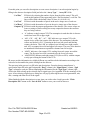
` NATIONAL OPTICAL ASTRONOMY OBSERVATORY SYSTEM INSTRUMENTATION GROUP 950 N. Cherry Ave. P. O. Box 26732 Tucson, Arizona 85726-6732 (520) 318-8000 FAX: (520) 318-8303 TORRENT Software User Manual for arrayDesc fclPlnDesc dewarDesc dheDesc sysConfig NOAO Document TRNT-AD-08-0006 Revision: 0 Authored by: Nick C. Buchholz Please send comments: [email protected] Doc. File TRNT-AD-08-0006 R0.doc Doc. Number TRNT-AD-08-0006 Created on 8/6/2010 Page 1 of 33 Revision History Version Date Approved Sections Affected 0 8/6/2010 All Remarks Initial draft release - aro Doc. File TRNT-AD-08-0006 R0.doc Doc. Number TRNT-AD-08-0006 Created on 8/6/2010 Page 2 of 33 Table of Contents Revision History ................................................................................................................ 2 Table of Contents............................................................................................................... 3 1.0 Introduction.............................................................................................................. 5 1.1. Who Needs to Use sysConfig and the Desc Programs ..........................................5 1.2 Why ****Desc....................................................................................................5 1.2.1 arrayDesc .................................................................................................... 5 1.2.2 fclPlnDesc.................................................................................................. 5 1.2.3 dewarDesc .................................................................................................... 6 1.2.4 dheDesc ......................................................................................................... 6 1.2 Why sysConfig .................................................................................................6 1.4 sysConfig Inputs and Outputs...........................................................................6 1.5 Standard Arguments to the programs.....................................................................7 2.0 arrayDesc User Manual ...................................................................................... 7 3.0 fclPlnDesc User Manual .................................................................................. 11 3.1 Copying a Dewar Functions Description .............................................................16 4.0 dewarDesc User Manual .................................................................................... 16 5.0 dheDesc User Manual........................................................................................ 20 6.0 sysConfig User Manual .................................................................................... 23 6.1 Using sysConfig to Create a Wire List. ..........................................................29 6.2 Creating a User Defaults List...............................................................................31 6.3 Creating Other Attributes Defaults List ...............................................................31 6.4 Assigning User Names to DHE Functions...........................................................31 6.5 Using the sysConfig Documentation Functions .............................................31 Appendix I TSM .cfg File Format............................................................................... 32 Appendix II Function and Signal Categories........................................................... 33 Doc. File TRNT-AD-08-0006 R0.doc Doc. Number TRNT-AD-08-0006 Created on 8/6/2010 Page 3 of 33 List of Figures Figure 1 – Welcome Screen .............................................................................................. 7 Figure 2 – Main sysConfig Screen .............................................................................. 8 Figure 3 – arrayDesc Main GUI Window.................................................................. 9 Figure 4 – fclPlnDesc Splash Screen........................................................................ 11 Figure 5 – fclPlnDesc Main Screen for a New Focal Plane ................................... 12 Figure 6 – fclPlnDesc Main Screen for Editing MosaicTest Focal Plane............. 14 Figure 7 – dewarDesc Splash Welcome Window....................................................... 17 Figure 8 – dewarDesc Main Screen for New Dewar ................................................. 18 Figure 9 – dewarDesc Main Screen for Editing an Existing Dewar....................... 19 Figure 10 – dheDesc Splash Welcome Screen ............................................................ 21 Figure 11 – dheDesc Main Edit Screen ..................................................................... 22 Figure 12 – sysConfig Splash Screen ........................................................................ 23 Figure 13 – sysConfig System Identification Screen ............................................... 24 Figure 14 – sysConfig Main Screen before Filling in Component Names............. 25 Figure 15 – sysConfig Main Screen with Component Details Complete............... 26 Figure 16 – basicCCD sysConfig Screen .................................................................. 27 Figure 17 – Partially Made Connection ........................................................................ 29 Figure 18 – Signal Value Display for Connection ........................................................ 30 Figure 19 – Component Display and Connection List after a Connection is Made.. 31 Doc. File TRNT-AD-08-0006 R0.doc Doc. Number TRNT-AD-08-0006 Created on 8/6/2010 Page 4 of 33 1.0 Introduction This document is the user manual for the Torrent programs arrayDesc, fclPlnDesc, dewarDesc, dheDesc and sysConfig. Section 1 describes the target audience and the functions preformed by each of the programs. Section 2 through Section 5 is the user manual for each of the Descriptor programs. Section 6 is the user manual for the sysConfig program. 1.1. Who Needs to Use sysConfig and the Desc Programs The descriptor programs and sysConfig are interactive programs written for detector engineers and scientists responsible for the integration of a TORRENT detector subsystem into an instrument. The programs are written to automate or simplify tasks currently done by hand and to ensure a consistent level of documentation for the detector controller integration task. 1.2 Why ****Desc The four descriptor programs were created to support the configuration of a Torrent detector controller system. They are GUI-based programs designed to allow the user to specify the configuration of the various parts of the detector controller in a consistent way and to document the decisions made during the process. 1.2.1 arrayDesc arrayDesc is a program that allows the user to describe a detector to be used in a focal plane. It allows the description of the pins on the detector, their designation, signal names and types and the minimum, maximum and nominal,voltage values that should be applied to the pin. The output of arrayDesc is a file that can be read by fclPlnDesc to allow the detector to be used in a focal plane. Detector files are identified by the detector type (sta1042, e2v44-82, site1K, orionII, etc.) and by an ID (normally either generic or the detector serial number). A generic description file can be read into the program and written as a unique detector by changing the ID field. Detector file names have the form DtctrName_ID=DtctrID.dsc. Example: e2v44-82_ID=generic.dsc or e2v44-82_ID=44627.dsc. 1.2.2 fclPlnDesc fclPlnDesc is a program that allows the user to describe a focal plane containing one or more detectors and a number of other functions (heaters, temperature sensors, etc.) associated with the focal plane. It allows the user to specifiy the detector to be used and the expected values for the auxilliary functions. The output of fclPlnDesc is a file that can be read by sysConfig to allow the engineer to use the description to configure the connections between the focal plane detector signals and focal plane functions to the Dewar connectors and thus to the DHE function connections. Focal plane files are identified by the focalPlane name, such as basicCCD, sta2wTrnt, and so forth. A focal plane description file will be stored in ${MONSOONHOME}/cfg/_detectors and will have a name like sta2wTrnt_FclPln.dsc or basicCCD_FclPln.dsc. Doc. File TRNT-AD-08-0006 R0.doc Doc. Number TRNT-AD-08-0006 Created on 8/6/2010 Page 5 of 33 1.2.3 dewarDesc dewarDesc 1.2.4 dheDesc dheDesc 1.2 Why sysConfig sysConfig is written to help insure that a Torrent detector controller system is properly set up and documented; that the system software collector, mborg, borg will be able to read and understand the eeprom data that resides in the TSM module EEPROM and describes how to start-up and initialize a TORRENT system. The collector program automatically creates the configuration file (*****_Config.csv) at system runtime using information provided by assimilate and sysConfig to determine the layout of the EEPROMs. The sysConfig program suite will allow an engineer to complete and document the following tasks and produce a consistent output format describing the results of the tasks: a. assign DHE hardware functions to Dewar pins and detector signals. b. describe the connections from array pin to Dewar connector pin to DHE TSM preAmp and/or Utility Pin. c. print a wire list to be used for making the correct connections described in (a.). d. set up and assign voltage levels to adjustable voltage supplies. e. assign user-friendly names to the detector signals and DHE functions connected to them. f. set maximum and minimum values to hardware function values to restrict voltages, etc. to safe values. g. assign warning and alarm error bands to functions to ensure safe operation of the detector. h. assign an initialization value to functions that is automatically set on system startup. i. assign a preliminary nominal value to functions that are used during detector optimization. j. produce a system document and file to describe all decisions made during the process. k. assign a page, line & column position for each function assigned for use in a detector telemetry and control console GUI. ?? 1.4 sysConfig Inputs and Outputs sysConfig uses the output created by assimilate and the files created by the descriptor files to determine the capabilities of the detector, Dewar and Torrent DHE hardware. The program will use the DHE TSM connector description, the Dewar connector description to allow the connection of DHE input and output signals to the Dewar connectors to the detector. After the engineer uses sysConfig to complete the tasks above for the required signals and hardware functions, the program will be able to create the following outputs: a. an EEPROM image in a file containing the results of tasks (d) through (g) in Section 0. b. a .cfg file to be used by eepStor and collector to describe the TSM eeprom layout. c. a wire list describing the connections to be made between the TSM preAmp boards and the Dewar connectors. Doc. File TRNT-AD-08-0006 R0.doc Doc. Number TRNT-AD-08-0006 Created on 8/6/2010 Page 6 of 33 d. a wire list describing the connections to be made between the Utility board and the Dewar connectors. e. a wire list describing the connections to be made between the Dewar connectors and the detector/focal plane pins. f. a text file describing the correspondence between user name, DHE function name and detector signal name. g. a file/documents describing the initial and default nominal values to be set for each DHE function used by the configuration. 1.5 Standard Arguments to the Programs Starting the programs in Linux is done by going to an xterm window and typing the appropriate command along with the command line arguments for the command. All of the commands share two arguments: -help – typing this command line argument with any of the programs will result in a display of all the arguments and the default values for that command. -stdout – this argument takes a parameter either True or False. If True the program will startup and print debug and error/warning messages to the xterm. If False it will only output warnings and errors to a Python display. 2.0 arrayDesc User Manual The arrayDesc program is started in Linux by typing a command line in an xterm window. The arrayDesc command line takes the following optional arguments with defaults in parentheses: Note that the argument and its value are seperated by an ascii space. -help -stdout -type <arrayType> -arrayID <arrayID> print help and exit print messages rather than display in label (True) The name of the Array being described (generic) The name of the Array being described (generic) To start a description of a new array type (e.g. e2v88-44) you would type: arrayDesc –type e2v88-44 –arrayID generic The result of this command should be a splash window like this: arrayDesc Splash Screen Figure 1 followed by the main arrayDesc GUI window shown in Figure 2. Doc. File TRNT-AD-08-0006 R0.doc Doc. Number TRNT-AD-08-0006 Created on 8/6/2010 Page 7 of 33 New Array GUI Screen Figure 2 Doc. File TRNT-AD-08-0006 R0.doc Doc. Number TRNT-AD-08-0006 Created on 8/6/2010 Page 8 of 33 Note the file read error message in the status display and the fact that the pin description area is blank indicating that no .dsc file with this array name was found. To edit an existing array description, the command (for the generic e2v44-82 detector) would be: > arrayDesc –type e2v88-44 –arrayID generic resulting in the following display with the details of pin descriptions filled in with previous work. arrayDesc Main GUI Window Figure 3 Doc. File TRNT-AD-08-0006 R0.doc Doc. Number TRNT-AD-08-0006 Created on 8/6/2010 Page 9 of 33 From this point you can edit a description or create a new description. A new description begins by filling in the detector description fields just below the “Array Type” , “Array ID” fields. “# of Pins” Fill this in by selecting the number of pins from the slider control. This will result in this number of lines appearing in the “Pin Descriptions” scroll list. The lines will be filled with default values of None, 0.0, 0.08 or 0.16. “# of Cols” Fill this in with the number of pixels in the active image area of each row. “# of Rows” Fill this in with the number of rows in the active image area of the detector. “Output Cfg” Fill this in with the output configuration of the detector. The correct values are letters or strings of letters telling how many outputs the detector has and how they are being read out. ‘A’ indicates a single output CCD. The assumption is made that this is detector reads from lower left to upper right. ‘AB’, ‘CD’, ‘AD’, ‘BC’, ‘AC’, ‘BD’ indicates a two output CCD, with outputs in two of the four corners of the detector. The assumption is that the corners are labeled A, B, C, D starting in the lower left corner and labeling counter clockwise. Thus ‘AB’ are outputs lower left and lower right corners, and ‘AD’ are outputs lower left and upper left corners. The rows of the detector are numbered from bottom to top and the columns from left to right. ‘ABCD’ indicates a four output CCD, reading from each corner toward the center. The first pixel received is assumed to be the lower left corner. ‘ABCDEFGH’ indicates and eight output CCD (like an OTA) with the outputs evenly spaced along the bottom of the CCD. IR arrays use this information in a slighly different way and decode the information according to the code used to descramble the pixels coming from the detector. The next step in the process is to fill in the pin descriptions. From the detector manufacturer’s specification sheet fill in the pin Designation (“Desg” column), the “Signal Name” column, “Sgnl Type” column for each pin. When completing the information for the “Sgnl Type” column, right click in the field to bring up the selection list for signal types. See Appendix II for the meanings of the types. After selecting a signal type a dialog box will pop up allowing the user to assign nominal, min, max, warning and alarm levels to the signal. When finished with the description (or at any time you wish to take a break) press the “Write Description File” button or the “Save & Exit” button to save your work for later use. Doc. File TRNT-AD-08-0006 R0.doc Doc. Number TRNT-AD-08-0006 Created on 8/6/2010 Page 10 of 33 3.0 fclPlnDesc User Manual The fclPlnDesc program is started in Linux by typing a command line in an xterm window. The fclplnDesc command line takes the following optional arguments with defaults in parentheses: Note the argument and its value are seperated by an ascii space. -help -stdout -fclpln <fclplnName> -arrays <arrayType> -mosRows <mosRows> -mosCols <mosCols> print help and exit print messages rather than display in label (True) The name of the focal plane being described (default) The type of detector in the focal plane ( “ ” ) The number of rows of detectors in the focal plane (1) The number of columns of detectors in the focal plane (1) To start a description of a new focal plane (e.g. sta1x4) using sta1042 detectors you would type: fclPlnDesc –fclpln sta1x4 –arrays sta1042 –mosRows 4 –mosCols 1 -orfclPlnDesc This would begin the description of a 1x4 mosaic of sta1042 detectors. The result of this command should be a welcome splash window like this: fclPlnDesc Splash Screen Figure 4 followed by the main fclPlnDesc GUI window for the first command as shownin Figure 5 or a similar window with no values filled in for the Focalplane Name, Array Type or other fields. Doc. File TRNT-AD-08-0006 R0.doc Doc. Number TRNT-AD-08-0006 Created on 8/6/2010 Page 11 of 33 fclPlnDesc Main Screen for a New Focal Plane Figure 5 Doc. File TRNT-AD-08-0006 R0.doc Doc. Number TRNT-AD-08-0006 Created on 8/6/2010 Page 12 of 33 If what you wish to do is edit an existing focal plane description, the command line would look like this: fclPlnDesc –fclpln mosaicTest which would result in a main GUI screen with the information you have already filled in displayed as shown in Figure 6. Doc. File TRNT-AD-08-0006 R0.doc Doc. Number TRNT-AD-08-0006 Created on 8/6/2010 Page 13 of 33 fclPlnDesc Main Screen for Editing MosaicTest Focal Plane Figure 6 From this point you can edit or create the new description. Fill-in the fields as needed by clicking in the field and typing in the response and hitting the <Return> or <Enter> key. “FclPlane Name” Type in the name of the focal plane you are creating or a new name to create a focal plane based on the current focal plane. Doc. File TRNT-AD-08-0006 R0.doc Doc. Number TRNT-AD-08-0006 Created on 8/6/2010 Page 14 of 33 “Array Type” Enter the array type name for a new focal plane. This must be an array type previously created and stored using arrayDesc. If editing, the array type may not be changed. “Mosaic Cols”, “Mosaic Rows” The number of columns or rows of detectors in the mosaic. If the focal plane is irregular or not rectangular, set one of rows or cols to 1 and the other to the number of detectors in the entire focal plane. Should not be changed when editing. “# of Arrays” Not usually used directly filled in from the values in the previous two fields. When the number of arrays has been determined, a number of entry fields will be created for the detector IDs of each detector in the focal plane. The fields are labeled “Arry1”, …. “Arry#”. As each name is typed and <Enter> or <Return> pressed a new page will be created in the notebook area labeled “Arry1”, …. “Arry#”. The first page in this area is always reserved for a virtual connector page called “Dewar Functions”. This page exists to contain the descriptions of Dewar functions like temperature sensors, focal plane heaters, etc. that are in the cryostat but not directly associated with a detector signal. This connector can be filled in by hand by filling in the various fields or it can be copied from another focal plane using the procedure in section 0. To fill in the Dewar Functions by hand complete the fields as follows: “Cnctr Type” Since this does not represent an actual physical connector use Misc or Unk. “# of Pins” Type in the number of functions required for the current Dewar. If you discover you need more pins at a later date you can increase the number. When you type the number of pins in the pin, display lines will be created in the scrolled entry area on the notebook page. The next step in the process is to fill in the pin descriptions. Fill in the information for each pin. “Desg” A designation (1, 2, A4, etc.) for the pin (used for sorting in later steps) the designation must be unique for each pin. “Signal Name” Select a unique, short descriptive name for the signal. Append a number to signals with identical names, such as Nc1, Temp1+, etc. “Sgnl Type” Select a signal type for each pin. Right click in the field to bring up the selection list for signal types. See Appendix II for the meanings of the types. After selecting a signal type, a dialog box will pop up allowing the user to assign nominal, min, max, warning and alarm levels to the signal. When finished with the description (or at any time you wish to take a break) press the “Write Description File” button or the “Save & Exit” button to save your work for later use. Doc. File TRNT-AD-08-0006 R0.doc Doc. Number TRNT-AD-08-0006 Created on 8/6/2010 Page 15 of 33 3.1 Copying a Dewar Functions Description If you wish to copy the Dewar Functions information from another description before filling in any of the DewarFunctions information, press the “Save & Exit” button to save the current state. If using emacs or xemacs, start the editor, split the window and open the .dsc file you just saved in one half and the dsc file you wish to copy from in the other half. If using vi or vim, open the two files in separate editors. In the new dsc file look for and delete the three lines below and anything after them: ########################################################################### # Connector Description for connector dfCnct CTR:dfCnct:unk:0 In the dsc file you are copying from you will find lines similar to the ones above. In the mosaicTest_FclPln.dsc file the lines are: ########################################################################## # Connector Description for connector Dewar Functions CTR:dfCnct:Misc:20 Select everything from the ####### line to the end of the file and copy it to the new dsc file at the last line and save the new dsc file. The next time you start fclPlnDesc to edit your new focal plane, the Dewar Functions page will be filled in. 4.0 dewarDesc User Manual The dewarDesc program is started in Linux by typing a command line in an xterm window. The dewarDesc command line takes the following optional arguments with defaults in parentheses. Note the argument and its value are seperated by an ascii space. -help -stdout -numCnct -dewar <dewarName> print help and exit print messages rather than display in label (True) the number of connectors on the Dewar wall (1) The name of the Dewar being described (default) To start a description of a new Dewar such as RCSpecDwr, you would type: dewarDesc –dewar RCSpecDwr This would begin the description of a Dewar called RCSpecDwr. If this name already existed dewarDesc would one the description for editing. The result of this command should be a welcome window as shown in 0. Doc. File TRNT-AD-08-0006 R0.doc Doc. Number TRNT-AD-08-0006 Created on 8/6/2010 Page 16 of 33 dewarDesc Splash Welcome Window Figure 7 followed for a new Dewar by the main dewarDesc GUI window as shown in 0. Doc. File TRNT-AD-08-0006 R0.doc Doc. Number TRNT-AD-08-0006 Created on 8/6/2010 Page 17 of 33 dewarDesc Main Screen for New Dewar Figure 8 or for an existing Dewar a main window with information filled in as in 0. Doc. File TRNT-AD-08-0006 R0.doc Doc. Number TRNT-AD-08-0006 Created on 8/6/2010 Page 18 of 33 dewarDesc Main Screen for Editing an Existing Dewar Figure 9 Doc. File TRNT-AD-08-0006 R0.doc Doc. Number TRNT-AD-08-0006 Created on 8/6/2010 Page 19 of 33 From this point you can edit or create the new description. Fill in the fields as needed by clicking in the field and typing in the response and hitting the <Return> or <Enter> key. “Dewar Name” Type in the name of the Dewar you are creating or a new name to create a Dewar based on the current one. “# of Cnctrs” Enter the number of connectors in the Dewar wall. The program will create entry fields for the name/designation of each connector. These names must be unique within a description and should match the designation on the Dewar. By filling in the name/designation of each connector you will create a notebook page for that connector. Once the page is created you can begin describing the connector by filling in the appropriate fields. “Cnctr Type” The type of the connector. This is a string name for the type such as Dtype, MilCirc, Misc or unk. “# of Pins” fill in the number of pins for the connector. When you type the number of pins in the pin, display lines will be created in the scrolled entry area on the notebook page. Note the program knows about “MilCirc” connectors and will automatically fill in the pin designations when the number of pins is filled in. Other types of detectors are not known and the Pin Designations will have to be completed by hand The next step in the process is to fill in the pin descriptions. Fill in the “Desg” field for each pin. The pin designation is a unique designation (1, 2, A4, etc.) for the pin (used for sorting in later steps). The rest of the fields are unnecessary for Dewar descriptions and can be ignored. When finished with the description (or at any time you wish to take a break) press the “Write Description File” button or the “Save & Exit” button to save your work for later use. If two connectors are identical except for their connector name, the second may be copied from the first connector. For example ‘JP3’ and ‘JP4’ are identical connectors in the RCSpecDwr. Once ‘JP3’ is filled in, select its page tab to display it then press the “Copy Connector” button. Now select the page tab for ‘JP4’. The page will be blank. Press the “Paste Connector” button to paste the JP3 description here also. 5.0 dheDesc User Manual The dheDesc program is started in Linux by typing a command line in an xterm window. The dheDesc command line takes the following optional arguments with defaults in parentheses: Note the argument and its value are seperated by an ascii space. -help -stdout -type <dheType> -dhe <dheName> print help and exit print messages rather than display in label (True) The type (TRNT or ORNG (NYI)) of Dhe being described (NONE) The name of the Dhe being described ( " " ) To start a description of a new DHE you would type: dheDesc –type TRNT –dhe generic2AFE Doc. File TRNT-AD-08-0006 R0.doc Doc. Number TRNT-AD-08-0006 Created on 8/6/2010 Page 20 of 33 This would begin the description of a DHE called generic2AFE. Note that at this time only Torrent DHEs can be described using this tool. In addition, since all Torrent systems will have two AFE boards, this DHE has already been described and is supplied with your distribution. The file is “/Monsoon/cfg/_common/generic2AFE_trntDHE.dsc”. To distinguish different DHEs, use the tool to open the generic2AFE file and the rename the DHE to something like “gen2AFE_ID=542”. Writing this to the disk will result in a file “/Monsoon/cfg/_common/ gen2AFE_ID=542_trnt.dsc”. The result of this command should be a welcome window like this: dheDesc Splash Welcome Screen Figure 10 followed by the main dheDesc GUI edit window as shown in Figure 11. Doc. File TRNT-AD-08-0006 R0.doc Doc. Number TRNT-AD-08-0006 Created on 8/6/2010 Page 21 of 33 dheDesc Main Edit Screen Figure 11 Doc. File TRNT-AD-08-0006 R0.doc Doc. Number TRNT-AD-08-0006 Created on 8/6/2010 Page 22 of 33 When editing a Torrent DHE description only two controls are really needed. The “Boards” button brings up a dialog box that allows the user to specify the serial numbers of the boards in the DHE being edited. The “Voltages” button allows the user to select the voltage levels to be used by this DHE. This information is used by the sysConfig program to document the desired voltage settings for the DHE. The ‘Blue’ control buttons are only useful if describing a DHE from the beginning. 6.0 sysConfig User Manual The sysConfig program is started in Linux by typing a command line in an xterm window. The sysConfig command line takes the following optional arguments with defaults in parentheses: Note the argument and its value are seperated by an ascii space. -help -stdout -sysName <sysName> -fclPlane <fpName> -dewar <dwrName> -dhe <dheName> print help and exit print messages rather than display in label (True) The system configuration name (default) The Focal Plane Name (fromFile) The dewar name (fromFile) The DHE name (fromFile) To start the description of a new system such as RCSpec, using the focal plan sta1x4 and the Dewar RCSpecDwr and the Torrent DHE gen2AFE_ID=542 you would type: sysConfig –sysName RCSpec –fclPlane sta1x4 –dewar RCSpecDwr –dhe gen2AFE_ID=542 -orsysConfig –sysName RCSpec and fill in the other fields when the sysConfig GUI appears. The result of this command should be a welcome window as displayed in Figure 12 sysConfig Splash Screen Figure 12 Doc. File TRNT-AD-08-0006 R0.doc Doc. Number TRNT-AD-08-0006 Created on 8/6/2010 Page 23 of 33 and followed a few seconds later by the system identification screen. sysConfig System Identification Screen Figure 13 When the fields on this screen are completed, pressing “OK” will remove the screen and bring up the sysConfig main GUI screen looking something the one shown in Figure 14. Doc. File TRNT-AD-08-0006 R0.doc Doc. Number TRNT-AD-08-0006 Created on 8/6/2010 Page 24 of 33 sysConfig Main Screen Before Filling in Component Names Figure 14 Doc. File TRNT-AD-08-0006 R0.doc Doc. Number TRNT-AD-08-0006 Created on 8/6/2010 Page 25 of 33 You should now fill in the “Focalplane Name”, “Dewar Name” and “Torrent DHE Name”. After pressing <Return> or <Enter> in each of the name fields the details for the named component will be filled in, resulting in a screen like 0. sysConfig Main screen with Component Details Complete Figure 15 Doc. File TRNT-AD-08-0006 R0.doc Doc. Number TRNT-AD-08-0006 Created on 8/6/2010 Page 26 of 33 At this point the user can begin the process of connecting the focal plane functions and detector signals to the Dewar wall connectors and then to the DHE function connection points. However, for our example system we will use the basicCCD sysem. This system consists of a focal plane with a single e2v44-82 engineering grade detector in a universal Dewar called mosTest with a prototype Torrent DHE controlling the detector. The sysConfig screen for the system is shown in 0. basicCCD sysConfig Screen Figure 16 Doc. File TRNT-AD-08-0006 R0.doc Doc. Number TRNT-AD-08-0006 Created on 8/6/2010 Page 27 of 33 The following is a concise explanation of the parts of the main screen before continuing with how to use the system. The topmost grey section is the status message area. Error, warning and information messages will appear in this scrollable area as well as in the log file for the session. All messages are logged for review in case of a programming or formatting error. The next area, with the blue background, is the File control section. Here you can change the directory for storing the description File and output files, change the system identity information with the “Edit System Info” button or initiate a read or write of the system description file using the "Read system config File" and "Write system config file" buttons. The next section is the system component display area, divided into three parts. On the left is the focal plane description area with the focal plane name, detector type and geometry fields and the notebook with a page for the Dewar Functions and a page for each array labeled Arry1 through N. The center part is the Dewar description area with the Dewar name, and a notebook page for each connector. The right part is the DHE description area with the DHE Name, The “Voltage” and “Boards” buttons and a notebook page for each group of function connections and connectors in the DHE transition module. The light grey area below the component display is the temporary area that displays the pins being included in the current connection along with the “Clear Selection” button to abort a connection before creating it. Next on the left is the connection list giving the currently active connections for the system. On the right is the controls display with “Do Connection” and “Delete Connection” buttons; three “sort by” buttons to determine how the wire list output will be sorted; “Set User Defaults” and “Set Attr Defaults” buttons and finally “Print” and “Write” buttons to initiate a print or write to disk of the five types of outputs that can be seperately output. NOTE: This may be replaced at a later time with a dialog box that will allow printing or writing additional information. Finally at the bottom of the screen are the “Load TSM EEPROM”, “Save & Exit” and “Exit (No Save)” buttons. Most of the controls in the system component display area disabled. This allows the user to review the settings made using the lower level description files. Disabled controls are light gray with darker gray lettering. Enabled controls are darker gray with black lettering. The main purposes of sysConfig is to document the design of the image acquisition system, specifically the focal plane Dewar and DHE component. Section 0 explains how to use sysConfig to create the wire list used to wire up the focal plane, Dewar and DHE connectors. It is also used to associate user names with DHE hardware functions and to assign starting nominal values to the various bias and clock rail voltages. Doc. File TRNT-AD-08-0006 R0.doc Doc. Number TRNT-AD-08-0006 Created on 8/6/2010 Page 28 of 33 6.1 Using sysConfig to Create a Wire List To connect a focal plane to the DHE the engineer must provide several pieces of information. One of these is the wire list. The wire list is a set of instructions to a techinician telling them what connections should be made in the system. The wire list can be broken down into two parts; a list of connections from the detectors and internal Dewar functions to the Dewar wall connectors and a list of connections from the Dewar wall connectors to the TSM preamp and utility boards and TSM auxilary connectors. Thes lists are created by connecting a pin on the focalplane to a Dewar pin and finally to a DHE pin. To make a connection the engineer clicks on a pin in each section of the sysConfig componets area. Selected pins are highlighted. See 0 for an example of a partial connection. When a pin from each section is selected, the user can press the “Do Connect” button to create the highlighted connection. This will create a line in the Connections area and pop up a window, as shown in 0, that will allow the engineer to set the nominal max and min values for the DHE function being used. If the engineer decides the proposed connection is faulty, he or she may use the “Clear Selection” button to erase the proposed connection. Once the connection is made and added to the Connections list the pins will be highlighted with a tan background. See 0. Partially Made Connection Figure 17 Doc. File TRNT-AD-08-0006 R0.doc Doc. Number TRNT-AD-08-0006 Created on 8/6/2010 Page 29 of 33 Signal Value Display for Connection Figure 18 Doc. File TRNT-AD-08-0006 R0.doc Doc. Number TRNT-AD-08-0006 Created on 8/6/2010 Page 30 of 33 Component Display and Connection List after a Connection is Made Figure 19 The cfg files for the hardware modules and Dewar/detector will contain information to prevent the user from connecting a clock function to a voltage without special overrides. 6.2 Creating a User Defaults List 6.3 Creating Other Attributes Defaults List 6.4 Assigning User Names to DHE Functions 6.5 Using the sysConfig Documentation Functions Doc. File TRNT-AD-08-0006 R0.doc Doc. Number TRNT-AD-08-0006 Created on 8/6/2010 Page 31 of 33 Appendix I TSM .cfg File Format Doc. File TRNT-AD-08-0006 R0.doc Doc. Number TRNT-AD-08-0006 Created on 8/6/2010 Page 32 of 33 Appendix II Function and Signal Categories The connections made by the sysConfig program are checked for consistency. The DHE function and the detector signal must have the same type to be connected. This is enforced by the program but a detector engineer can override this requirement. What follows is all the signal and function types used by the assimilate program. The last three (CMND,CNST,SFTW) are generally not used by detectors. AGND a detector analog ground signal. BIAS a detector bias voltage. DCLK detector clock signal – a control clock for the detector. These break down into an UpperRail, a LowerRail and a logical level. Connecting any one of the three signals to a detector pin automatically connects the other two signals. DPWR a detector power signal – a voltage usually connected to a fixed bias level. used by both dewar and DHE descriptions. DVLT a detector voltage not otherwise classified (e.g. logical controls as in OTA’s. or hardware gain controls). LGCL an attribute that is a logical connection to the detector (i.e. rowCount, Number of outputs, pipeline enables, etc.) OGND other detector ground signals. TEMP a temperature control signal. VOUT a detector video output. This breaks out into the video signal and an offset voltage for that signal. NONE an attribute that does not connect to the detector (i.e. power module control signals, telemetry read back attributes, etc.) CMND CNST SFTW connects to Dewar only through other values. Doc. File TRNT-AD-08-0006 R0.doc Doc. Number TRNT-AD-08-0006 Created on 8/6/2010 Page 33 of 33