1
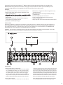
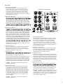
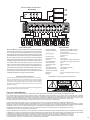
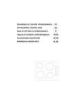
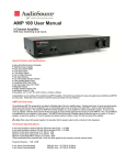
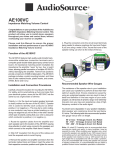
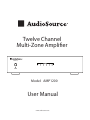
Twelve Channel
Multi-Zone Amplifier
AMP1200
Model: AMP1200
User Manual
www.audiosource.net
Thank you for purchasing the AudioSource ® AMP1200 Twelve Channel Multi-Zone Amplifier. The versatility of the
AMP1200 makes it the perfect choice for almost every type of custom multi-room audio system. Its tabletop or rackmountable design allows it to be integrated easily into high-end whole house audio systems.
FEATURES:
• 12 channels (6 stereo zones) in one convenient enclosure
• Stable Class AB design delivers superior audiophile sound
quality and performance
• Bridgeable channel outputs provide additional power
when needed
• Independent channel gain controls allow the output of
each speaker to be perfectly matched
• Switchable 115/230V input voltage
• Manual, auto, or triggered on/off for integration into any
automated system
• Multi-stage protection circuitry for reliability and easy
troubleshooting
• Installer-friendly setup and connections
• Can be converted easily between rack-mount and
tabletop configurations
• Heavy-duty steel chassis with brushed aluminum faceplate
INSTALLATION:
AudioSource amplifiers are designed to help deliver a great audio experience. However, where you place the amplifier can
have a large effect on the performance you receive, and the life of the unit. If you are not rack-mounting the amplifier, posi
tion it with all feet resting on a solid level surface. Be sure that the amplifier is in a well-ventilated area and DO NOT install
the amplifier near a source of heat or in an extremely humid or wet location.
-
CAUTION: All connections and switching must be done with the amplifier’s power switch positioned to ‘Off’. Connect the
power cord last to be sure that the amplifier is off during all of your connections and set up.
AMP1200
Fuse:T8AL 250VAC FOR 115VAC 60Hz
Fuse:T4AL 250AVC FOR 230VAC 50Hz
3076079
Date Code:
FRONT PANEL:
1. Master Power Switch / Indicator LED
Front panel pushbutton power switch turns the amplifier
on and off. When the switch is on and the indicator LED
is red, the amplifier is in standby mode. The remote turn
on switch (located on the rear) is either in the “trigger”
or “auto” position. When the LED is blue, the amplifier is
fully active. The master power switch will turn off the am plifier no matter which power mode has been selected.
indicate its operational status.These indicators provide quick
and easy troubleshooting of the system. If the circuitry deter
mines that a channel must be shut down due to excessive
heat or low impedance (a short), only the channels that are
affected will be turned off causing the zone LED to turn red.
The remaining zones will continue to operate and maintain a
blue LED status. Once the condition has been corrected for
the zone in question, the status LED will return to blue.
2. Zone Status Indicators
Each pair of channels or zones has a bi-color LED to
Note: When the power LED is red and the zone status LEDS
are not lit (off) indicates the unit is in stand by mode.
-
(2)
REAR PANEL:
3. BUS Line Inputs / Outputs
The AMP1200 has two common or BUS inputs that
receives audio signals from standard line-level audio
sources and sends them to any or all channels. The BUS
line outputs are direct feed-through to allow the BUS
inputs to be fed to other amplifiers. Be sure to use high
quality RCA cables that feature low impedance, shielding
and high quality connectors.
4. Remote Turn-On Switch
This switch selects the turn-on stimuli that will put the ampli
CLOSE UP OF CONNECTIONS
-
voltage going into the trigger input to activate the amplifier.
“Auto” setting senses a signal on the RCA line-level inputs
and automatically puts the amp in ready mode. “On” setting
puts the amp constantly in ready mode so that it can be
controlled by the master power switch on the front panel.
minutes to return from ready to standby mode.
5. Trigger Input / Output
The trigger input is a handy feature when connecting the
plug jack will accept a 3-30V AC/DC output from another
device, or from a separate power supply. When the trigger
input is energized, the amp turns from standby to ON mode.
When using the AMP1200 with a receiver without a trigger
output, the voltage can come from a 12V wall wart (3.5mm
tip-positive connector) plugged into the receiver’s switched
outlet and the trigger input. The AMP1200 can also provide
an output trigger voltage (12DC @500mA max.) to turn on
and off other devices in the audio system. When the ampli
Note : Remember there is a delay of approximately 15
minutes before the amplifier goes to standby when using
the “Auto” turn-on mode.
6. Channel Gain Control
Each channel has its own independent level adjustment.
This allows the output level of each speaker to be per
fectly matched to its area. It can also be used to limit the
maximum audio level in a certain area.
7. Bridging Switch
9. Speaker Output Terminals
The AMP1200 uses high quality Phoenix style connectors
for the speaker connections. Use 14-18 gauge stranded
two-conductor loudspeaker wire. Ensure that at least
2 inches of each conductor are separated. Strip away
¼ inch of insulation from each conductor. Connect the
appropriate conductor to each screw terminal, observing
correct polarity. Also, please observe proper speaker wir
ing when bridging channels.
10. Individual Channel Input
All twelve channels have their own dedicated input that
allows the connection of audio sources in addition to
the common BUS inputs. This is useful when using the
AMP1200 with an audio matrix switcher.
Note: The minimum impedance for bridged channels is 8
ohms. Also, please observe the proper speaker wiring when
bridging channels. Input selection and volume settings for
bridged channels will be controlled by the left channel. “BR”
is bridged mode and “ST” is non-bridged or stereo mode.
11. AC Voltage Switch
The unit is set at the factory for 115V U.S. operation; simply
connect the included IEC power cord to your wall outlet.
For 230V operation, move the voltage selector switch to the
230V position. When operating at 230V the internal fuse
located in the IEC socket should also be changed. In most
230V applications a separate power cord will be required
and is not included.
CAUTION: Only change switch positions when the
amplifier is turned off.
12. IEC Power Connector
The unit comes with an IEC jack that permits removal of
combined to increase the total power output. This is helpful
when extra power is needed in certain areas.
8. Input Selection Switch
Each channel is capable of delivering the source from
many inputs. The three main inputs are BUS 1, BUS 2
and LINE IN. The selection for these inputs is done via
the Input Selection switch associated with each channel.
Select the desired source input. Set the Input Selection
switch to BUS 1 (will play source connected to the BUS
1 input), BUS 2 (will play source connected to the BUS
2 input) or LINE IN (will play source connected to that
channel’s LINE IN).
-
ing the power cord for different countries. The IEC
socket also houses the main fuse holder. Plug the power
cord supplied with the amplifier into the amplifier and a
grounded wall outlet or appropriate surge protector.
-
CAUTION: DO NOT plug the amplifier’s power cord into
a switched outlet, such as what is provided on some Sur
round Receivers. If you wish to have the amplifier turn on
when the Receiver is powered up, use one of the power
modes, such as Trigger or Auto.
CAUTION: Only change switch positions when the
amplifier is turned off.
(3)
TYPICAL 6 ROOM INSTALLATION
AM/FM RECEIVER
NOTES ABOUT HUM:
SPECIFICATIONS:
While the AMP1200 has been designed to minimize the possibility
of hum in the audio system, it is still possible that a hum will occur
in rare circumstances. Its safety grounding can create a path for
small amounts of 60 Hz energy to travel trough the line-level audio
system. While not dangerous, this energy can cause difficulty with
the auto signal sensing circuit, and at the very least will interfere
with the quiet enjoyment of your system. The first course of action
should be trying to make sure that all of the audio components are
connected to either the same electrical outlet, or at least into the
same circuit branch. Next, cable TV systems are notoriously the
culprit, so be sure to try disconnecting all coaxial feeds that are
connected to the system. If this solves the problem, install a coaxial
line isolator and reconnect the system. In the very worst case, a
line-level audio isolator/transformer connected to the line-in of the
subwoofer amplifier will usually solve the problem.
Rated Power Output:
Bridged Power Output:
Weight:
30 lbs.
Input Sensitivity:
Important Safety Instructions
To reduce the risk of electric shock, do not remove cover. No user service
able parts inside. Refer servicing to qualified personnel. To reduce the risk
of fire and shock do not expose unit to rain or moisture. The unit should be
connected to an earth grounded AC electrical socket. The unit should be
operated in a well ventilated area. Minimum clearance is 2 inches from the
ventilation openings.
Input Impedance:
Frequency Response:
Distortion:
Distortion (Bridged):
Channel Crosstalk:
Signal to Noise Ratio:
Efficiency:
Power Requirements:
Stand-By Power Rating:
Auto Turn-On Sensitivity:
Dimensions:
40 Watts per channel RMS at 8 ohms
80 Watts per channel RMS at 8 ohms
(8 ohm minimum)
380 mV for full output with all level
controls at max.
18K ohm
5 Hz to 72 kHz
.005% THD 20 Hz-20 kHz @ 30W (8 ohm)
.010% THD 20 Hz-20 kHz @ 80W (8 ohm)
80 dB
105 dB A-weighted
63%
115/230 VAC, 50 Hz/60 Hz
115V, 0.264W *
13.7mV
16.7” W x 4” H (including feet) x 14.25” D
-
* The AMP1200 complies with the CE EuP directive.
Note: Unit is set at the factory for 120V operation. Be sure to change the fuse
(4A rating) before switching to 230V operation.
Two Year Limited Warranty
AudioSource, a division of Peak Audio Group, warrants this product against defects in materials and workmanship for a limited period of time.
For a period of two (2) years from date of original purchase, we will repair or replace the product, at our option, without charge for parts. Customer
must pay for all labor charges associated with the removal and re-installation of speakers for the limited period and all parts and labor charges after
the limited warranty period expires. The limited warranty period for factory refurbished products expires after ninety (90) days from date of original
purchase. This limited warranty applies only to purchases from authorized AudioSource Retailers or Distributors. This limited
warranty is extended only to the original purchaser and is valid only to consumers in the United States.
Consumers are required to provide a copy of the original sales invoice from an authorized AudioSource Retailer or Distributor when
making a claim against this limited warranty. This limited warranty only covers failures due to defects in materials or workmanship that occur during
normal use. It does not cover failures resulting from accident, fire, flood, misuse, abuse, neglect, mishandling, misapplication, alteration, faulty installation,
modification, service by anyone other than AudioSource, or damage that is attributable to Acts of God. It does not cover costs of
transportation to AudioSource or damage in transit. The customer should return their defective product, freight prepaid and insured,
to AudioSource only after receiving a Return Authorization.
Repair or replacement under the terms of this warranty does not extend the term of this warranty. Should a product prove to be defective in workmanship
or material, the consumer's sole remedies will be repair or replacement as provided under the terms of this warranty. If the defective product is discontinued
AudioSource may replace the product with an equivalent or superior product at its option. Any cost of re-installation or repair of wall
or ceiling surface is the sole responsibility of the customer and that cost shall not be the responsibility of AudioSource. Under no
circumstances shall AudioSource be liable for loss or damage, direct, consequential or incidental, arising out of the use of or inability
to use the product. There are no express warranties other than described above.
(4)