1
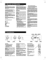
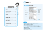
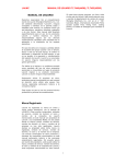
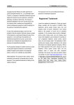
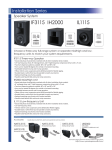
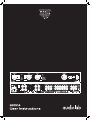
L OOO 1NIW-0 LHY 30093
Yn'09'gejopnemmv //:d99U
LILLEY OSY LO :Xed
004477 O87 LO ‘ISL
NX9 623d uopbuinuny
YyJed sSSauISNg SUILUJE
qunog UBISJSNOS
‘asnoH AVI
де орп\уу
RECORD VOLUME
pre
— mute
— integrated и
—— pre-power
pre power AV
S200A eV ele (ee
Г RIGHT 7 OUTPUT — TAPE2 TAPE 1 To — TUNER CD —
220-230V-50Hz 440W я = = С €
NN NN z
A VV ZN у и N
Da a Lo A,
FUSE T2.5AL 250V e 6. e O ==. e.
“ IAE y NA > ©: Sot
ras NTR TRS use. (@) №1090
я Sime? " Sime?
Vala, MEN UN MUA MEN UN ЧЕ
Da a, a Na
| as | em | ons | mu |]
LASER | LAS LA “ay, LAS
A X a y a
Ne м X à De Nez Na N/A NG
DT 7 = am Г, ыы
99 IAG-A.LAB
AUDIOLAB, HUNTINGDON
©
CAUTION ATTENTION
NAME: INTEGRATED MODEL:8200A S.No. == 2 "e © UNITED KINGDOM PE29 6XU
RISK OF ELECTRIC SHOCK RISQUE DE CHOC ELECTRIQUE | QU (e) a min WWW.AUDIOLAB.CO.UK
NE PAS OUVRIR
S200A й
User Instructions audiolab
1: Statutory & Safety Information
NN RISK OF ELECTRIC SHOCK /N
DO NOT OPEN 5
TO REDUCE THE RISK OF ELECTRIC SHOCK DO NOT REMOVE COVER
NO USER-REMOVEABLE PARTS INSIDE
REFER SERVICING TO QUALIFIED PERSONNEL
ADVERTISSEMENT: RISQUE DE CHOC ELECTRIQUE-
NE PAS OUVRIR
This symbol indicates that there are important
operating and maintenance instructions in the
literature accompanying this unit.
This symbol indicates that dangerous voltage
constituting a risk of electric shock is present
within this unit.
Read these instructions.
Keep these instructions. In the event that you pass the product to a third
party this instruction manual should be provided along with the product.
Heed all warnings.
Follow all instructions.
Do not use this apparatus near water.
Clean only with dry cloth.
Do not block any ventilation openings.
Install in accordance with the manufacturer's instructions.
Do not install near any heat sources such as radiators, heat registers,
stoves, or other apparatus (including amplifiers) that produce heat.
Do not defeat the safety purpose of the polarized or grounding type plug.
A polarized plug has two blades with one wider than the other. A
grounding type plug has two blades and a third grounding prong. The
wider blade or the third prong are provided for your safety. If the provided
plug does not fit into your outlet, consult an electrician for replacement of
the obsolete outlet.
Protect the power cord from being walked on or pinched, particularly at
plugs, convenience receptacles, and the point where they exit from the
apparatus.
Use only attachments/accessories specified by the manufacturer.
Use only with a cart, stand, tripod, bracket, or table
specified by the manufacturer, or sold with the apparatus.
When a cart is used, use caution when moving the
cart/apparatus combination fo avoid injury from tip-over.
Unplug this apparatus during lightning storms or when unused for long
periods of time.
Refer all servicing fo qualified service personnel. Servicing is required
when the apparatus has been damaged in any way, such as power-
supply cord or plug is damaged, liquid has been spilled or objects have
fallen into the apparatus, the apparatus has been exposed to rain or
moisture, does not operate normally, or hias been dropped.
Warning: To reduce the risk of fire or electrical shock, do not expose this
product to rain or moisture. The product must not be exposed to dripping
and splashing and no object filled with liquids such as a vase of flowers
should be placed on the product.
No naked flame sources such as candles should be placed on the
produc.
Caution: Changes or modifications not expressly approved by the
manufacturer could void the user's authority to operate this device.
This equipment has been tested and found to comply with the limits for a
Class B digitial device, pursuant to part 15 of the FCC rules. These limits
are designed to provide reasonable protection against harmful
interference in a residential installation. This equipment generates, uses
and can radiate radio frequency energy and, if not installed and used in
accordance with the instructions, may cause harmful interference to radio
or television reception, which can be determined by tuning the equipment
off and on, the user is encouraged to try fo correct the interference by one
or more of the following measures:
Re-orientate or re-locate the receiving antenna. Increase the separation
between the equipment and the receiver. Connect the equipment into an
outlet on a circuit different from that to which the receiver is connected.
Consult the dealer or an experienced radio/TV technician for help.
Important Note: The batteries supplied with this unit should be treated
with care and not punctured or damaged. Used batteries should be
disposed of in full conformity with recycling regulations in your area.
NEVER dispose of batteries in a fire orin the general rubbish.
6: Specifications
Rated Output Power
60 W (18 dBW) per channel into rated load impedance (8 Ohms)
with both channels driven
Inputs
CD, TUNER, AUX, VIDEO, TAPE 1, TAPE 2: 125mV/20k<2 IHF
POWER AMP: 782 mV/47 kQ
Gain
PRE-AMP: 9dB@ 1kHz
POWER AMP: 29.0dB @ 1kHz.
Signal To Noise Ratio
CD, TUNER, AUX, VIDEO, TAPE 1, TAPE 2:
Better than 80dB(IHF, rel. 0.5V pre-amp output)
POWER AMP: better than 80dB(IHF rel. 0 dBW)
Frequency Response
CD, TUNER, AUX, VIDEO, TAPE 1, TAPE 2 and POWER AMP:
20 H7-20 kHz +0.5 dB: 1Hz-65 kHz -3 dB.
Total Harmonic Distortion & Noise
Less than 0.07 %
Channel Balance
Within 1dB
Channel Separation
Betterthan 60 dB @ 1 kHz any input
Crosstalk
Better than 80 dB @ 1 kHz
Polarity (phase)
Non-inverting for all inputs and outputs
Pre-amp Output
PRE OUT 1 and PRE OUT 2: Output Impedance 100
Maximum Output >7.3V RMS
Correct Disposal of this product. This marking indicates that this product should not be disposed with other
household wastes throughout the EU. To prevent possible harm to the environment or human health from
uncontrolled waste disposal, recycle it responsibly to promote the sustainable reuse of material resources. To
return your used device, please use the return and collection systems or contact the retailer where the product
Headphone Output
Output impedance: 330 ®
(Suitable for headphones 8 2-2 k© impedance)
Record Output
VIDEO OUT, TAPE 1 OUT, TAPE 2 OUT:
Outputimpedance: 1kQ.
Gain from input to record output 0dB (x1)
Muting
Muting controlled manually or automatically
Accessories Supplied
AC Power Cord
Instruction Manual
8200RC Remote Control with 2 x AA batteries
Operating Temperature Range
10-35°C
Power Requirements (Depending on Region)
50-60Hz 100 V, 110-120 V, and 220-230 V models available
Maximum Power Consumption: 440 VA
Dimensions (WXHXD)
445x74x335 mm - including feet, terminals and controls
445 x 64 x 302 mm- excluding feet, terminals and controls
Weight
Net: 7.4kg
Shipping: 8.8 kg
Audiolab reserves the right to alter design and specification
without notice. Specification may vary for different countries.
Audiolab is a member of the International Audio Group.
_ was purchased. They can take this product for environmental safe recycling.
IAG-A.LAB
Mains supply and safety
Mains Supply: The mains operating voltage of all Audiolab units is
shown on the rear panel. If this does not match the voltage in your area,
consultyour dealer.
The mains supply fuse is located on the rear panel of the unit. If it has
broken, check for any obvious cause before replacing the fuse with one of
the correct rating and type. The fuse values are:
220-230V (UK, Korea, etc.) T2.5AL 20mm Slow Blow
100-120V (USA, Japan, et) ~~ T4.0AL 20mm Slow Blow
Fuse Carrier The fuse is located in a slide-in
carrier which also contains a spare
fuse. The fuse carrier can only be
pulled out after the IEC power cord is
unplugged. When the carrier is
opened the first fuse to be seen is the
spare fuse. Remove and safely
| dispose of the fuse with the blown
IEC Mains Connector link before replacing it.
Class II construction double insulated. This product must not be
connected to earth.
Power Cord: An AC power cord is normally supplied with a mains plug
suitable for your area. If you have any doubts, consult your dealer about
obtaining a suitable power cord.
Important notice to UK users
The appliance cord is terminated with a UK approved mains plug fitted
with a 5A fuse. If the fuse needs to be replaced, an ASTA or BSI approved
BS1362 fuse rated at 5A must be used. If you need to change the mains
plug, remove the fuse and dispose of this plug safely immediately after
cutting itfrom the cord.
Connecting a Mains Plug
Thewires in the mains lead are coloured in accordance with the code:
Blue: NEUTRAL; Brown: LIVE:
As these colours may not correspond to the coloured markings identifying
the terminals in your plug, proceed as follows:
The BLUE wire must be connected
to the terminal marked with the
letter N or coloured BLUE or
BLACK. The BROWN wire must be
connected to the terminal marked
with the letter L or coloured (Neutral)
BROWN or RED.
Power Amplifier Protection Circuits
Short Circuit Protection: If the output terminals are connected together or there
is a short caused by a faulty speaker or connecting lead, the amplifier will mute and
un-mute until the fault condition is removed.
DC Offset Protection: If there is an internal or external fault which may cause DC
voltage to be presented to the loudspeaker, the amplifier will mute and stay muted
until the faultis removed.
Thermal Protection: If the amplifier is driven excessively for long periods, or the
output devices are pushed beyond their safe operating area, the amplifier will
switch off and then switch back on again when it has cooled down.
In all cases, it the amplifier does not respond to remedial action, consult your dealer.
5: Service and Warranty
Servicing
Servicing of Audiolab produds should only be carried out by
authorised service agents. If service is required the equipment
should be returned, securely packaged, preferably using original
packaging, to your dealer.
In the UK equipment may be returned to the IAG Service Contra.
Alwaystelephone before returning any equipment.
A nots should be enclosed giving your name, address, telephone
number, and a brist description of the reason for retum.
If you require Service outside the Warranty period, do not hesitate
to contact your dealer.
While cleaning is in progress the AC power cord must be
unplugged from the AC power supply socket.
Any grease or dirt on the equipment may bs removed with a soft,
lint-free cloth slightly moistened with a mild solution of warm
water and detergent or washing-up liquid. Do not use any other
solutions or solvents.
Retain original packaging for transporting equipment.
It you have any queries regarding the use of Audiolab equipment,
consultyour dealer,
Service Addresses, UK
IAG Sarvica Cantre
Unit 4
St Margaret's Way
Stukeley Meadows Ind, Estate
Huntingdon
Cambs
PE29 6EB
England
Tel:+44 (0)1480 452561
Fax: +44 (0)1480 13403
Audiolab limited warranty
Audiolab Lid. warrants this produd, subject to the terms and
conditions below, to ba free from defeds in materials and
workmanship. During the warranty pariod Audiolab will rapair or
replace (ot Audiolab's option) this product, or any defective part in
this product, if it is found to be defective due to faulty materials,
workmanship or fundion. Thé warranty period may vary from
touniryto country.
Terms and conditions:
The warranty starts on the date of purchase (or the date of delivery
if this is later).
You must provide proof of purchase / delivery before work can be
carried out. Without this proof, any work carried out will be
chargeable to you.
All work will be carried out by Audiolab or its authorised agents or
distributors. Any uneuthorisad repair or modification will void this
warranty,
If any part is no longer available it will replaced with a fundional
replacement part,
Any parts that are replaced will become the property of Audiolab.
Any repair or replacement under this worranty will not extend the
period of warranty.
This warranty is valid only in the country of purchase, applies only to
tha first purchaser and is not transferable.
The following are not covered:
e Products on which the serial number hos been removed,
altered or otherwise mada illegible.
e Normal wearand tear and cosmeticdamage.
e Transportation orinstallation ofthe product.
e Accidental damage, faults caused by commercial use, ads of
God, incorrect installation, connection ar packaging, misuse,
negled or careless operation or handling of the product which
is not in accordance with Audiolab's user instructions.
e Equipment that hos been operated in conjunction with
unsuitable, inappropriate or faulty apparatus,
e Rapairs or alterations carried out by parties other than
2: Introduction
Audiolab or its authorisad agents or distributors.
e Products net purchased from an Audiolab authorised dealer.
e Produds that wera not new at the time of original purchase.
» Produdssold ‘esis’, 'as seen’ or 'with al | faults.
Repairs or replacements cs provided under this warranty are the
exclusive remedy of the consumer. Audiolab shall not be liable for
any inddental or consequential damages for breadh of any express
or implied warranty in this product. Except to the extent prohibited
by law, this warranty Is exdusive and in liau of all other warrantles
whatsoaver, both express and implied, including, but not limited
to, the warranty of merchantability and fitness for a practical
purpose.
This warranty provides benefits that are additional fo and do not
affect your statutory rights as a consumer.
Some countries and US states do not allow the exclusion or
limitation of incidental or consaquentinl damages or implied
warranties so the exdusions in the paragraph above may not
apply to you. This warranty gives you specific legal rights, and you
may have other statutory rights, which vary from state to state or
couniry to country.
How to claim:
To obicin warranty service contad the Audiolab authorised dealer
from which you purchased this produd. Do not despatch goods
without the prior agreement of the dealer, Audiolab or their
authorised distributors.
if asked to return products for inspedion and/or repair, pack
carefully, preferably In the original cartons or packaging affording
an equal degree of protedion, and return prepaid. If unsuitable
packoging is used, Audiolab may make a charge for the supply of
new packaging.
Insurance is recommended as goods are returned at owner's risk.
Audiolab or their authorised distributors cannot be held liable for
loss or damage in transit.
Packing, insurance and freight on the return journey will be paid by
Audiolab er their authorised agents or distributor if corredive work
proves to be nacessory.
MUTE LED REMOTE
ECON,
MODE
VOLUME
RECORD INPUT”
SELECTOR SELECTOR
Unpacking
Unpack the produd fully. The carton should contain
e TheAvdiciab 82004 integrated amplifier
® OnelEC power cord suitable for yourarea
e OnsRamote Handset with two AA butterles
e Thisinstrudion manual.
If any item is missing or damaged report this to your dealer as
soon as possible.
Retain the packing for future safe transport of your amplifier. If
you dispose of the packing, do so with regard to any recycling
regulations in your area.
Inserting Batteries in the Handset
The battery compartment ison the rear ofthe handset, Unwrap the
batteries, open the compartment cover and Insert the batteries.
Followthe polarity indications in the battery compartmant,
Always replace batteries in pairs. Use new batteries of the same
type and rating, ideally fromthe same manufacturer.
Controls And Functions
Power Switch
When power is switched on the 82004 is muted for 8 seconds.
MODE
SWITCH
Always switch the power off before hanging connedions.
Input Selactor
Turn to seled the listening source. The 8200A mutes briefly when a
new input is selected.
Volume Control
Adjusts playing volume. Always turn the volume up gradually.
Racord Salactor
Turn to seled source to record to Tape 1, Tape 2 or Video. The
connedions can also be used to connect to amy recorder with
analogue inputs such as a CD, DAT recorder, etc.
Record selector and input selector operate indapendently. It is
possible to record from any source whilst listening to another.
Mode Switch
Selec “integrated” whan using 8200A as an integrated amplifier.
Selec “mute” to tum off pre-amplifier outputs, loudspeakers or
headphones. See sedion 4 for further details.
Headphones Socket
Socket for connection of headphones. Unplug headphones when
not in usa. Connecting headphones mutes the |oudspaakers and
disconnecis the pre-amplifier outputs and power amplifier inputs.
VOLUME HEADPHONE *
CONTROL SOCKET
Remote Handset
Buttons shown in white control the 82004.
Buttons shown in grey operate Audiolab CD
players and have no effecton tha 82004.
As the handset uses RCS coding it wil| operate
many other players. Chedk with your dealer.
Mute
Toggles mute On/off, Doss not fundion if the
MODE switch on the front panel is setto mute.
Input
Press ta seloct listening source. The INPUT
seladior onthe front panel turns.
If you wish to record, the record input must be
seleded manually.
Volume
Press vOL+/- to raise or lower the volume. The
VOLUME control on the front panel turns.
RED=Muts On CONTROL SENSOR RED Power On
= Ме УП = run
T tal
audiblab
О! О!
ОО! 010:
Di
;
Ah
ЧР
RIGHT OUTPUT LEFT POWER PRE TAPE 2 TAPE 1 VIDEO AUX TUNER CD
220-230V-50Hz 440W [a [ | | | | 1 OUT IN OUT IN OUT IN C €
oD. 98 DVD 000 600000 000:
. —_. *
ee ' es eee 00: 000 I
INPUT — OUTPUT SALAS
AN op | nena AN | NAME: INTEGRATED MODEL: 8200A olab © |] pureza ox
| Y | |
| пуб | MAINS RIGHT LEFT POWER PRE-[ Igo) loo AUX|| Y |? cp, cor
HOLDER | INPUT LOUDSPEAKER TERMINALS AMPLIFIER AMPLIFIER | | | | | | Y | | '
INPUT OUTPUTS TAPEZ TAPE 1 DVD,ETC
Signal Connections Standard Loudspeaker Connection Connecting Loudspeakers
CD, TUNER, AUX, VIDEO IN, TAPE 1 IN, TAPE 2 IN Switch power off when connecting loudspeakers.
The six inputs may be used for connecting any line level source. | [YT ie [O Use good quality low resistance loudspeaker cable.
— 80+ + + + 68 68 + —0 Q + Connect the Positive RED (+) terminal of the
VIDEO OUT, TAPE 1 OUT, TAPE20UT 65 69 | amplifier to the Positive (++) RED terminal of the
Three sets of record outputs for connection of up to three stereo i loudspeaker. Connect the Negative (-) BLACK
audio recorders, e.g. tape recorder, CD recorder, audio recording | _ 69 æ _ _ ón ® | | terminals similarly.
input of DVD, MP3, etc. AUTOR тентом When connecting loudspeakers tighten the
PRE-AMP OUT 1 &2 /N eines | wold № terminals securely by hand.
Low impedance (100 ohm) pre-amplifier outputs for driving y (er switching box or headohone ad h d set of speak ло! Make there are no loose strands of wire which could
external power amplifiers, sub-woofers or signal processors. Long ou can connect a speaker switching box or headphone adaptor to the unused set of speaker terminals cause shorts.
cables may be used if required. Pre-amp outputs are switched off Bi-Wired Loudspeaker Connection jm Speaker
when integrated mode is selected or whenever amplifier is muted. Cables
POWER AMP IN Loudspeaker bi-wiring offers improved sound quality because high and low frequency signals are carried
0 20 =
eo . . mm
For driving the power amplifier input directly from an external individually to the loudspeaker drive units. + RED
source. Only operates when pre power AV mode is selected. — BLACK
LOUDSPEAKER TERMINALS | OUTPUT pere
Two sets of loudspeaker output terminals connected in parallel. —e Qt as ds + —@ 9 +
GROUND mm h
Use only if phono pre-amplifier and turntable are used and both æ æ |
are Class Il double insulated (no earth connection). In this case the -
ground terminal can be connected to the metalwork of these units e EN —00+
to eliminate residual hum. The ground terminal must not be used E Г IL 3 Connecting
as a safety earth. If in doubt consult your dealer. Cables
Operating Modes MODE POWER AMP IN | PREAMPOUTIR2 rt ÓN LOUDSPEAKERS
Although the 8200A is an integrated amplifier, it can function as a separate pre-amplifier and ore
power amplifier. This allows the unit to be used in a variety of stereo and multichannel modes. ACTIVE
NOTE: When switching modes, the making and breaking of connections may momentarily — Mute ACTIVE
operate the muting function on the 8200A. — integrated
ACTIVE OPERATIONAL
Integrated Mode J
The pre-amplifier section is internally connected to the power amplifier. Pre-amp outputs are | Ресреме ACTIVE | OPERATIONAL
not operational. External subwoofers, processors, or amplifiers will not receive any signal. pre power AV ACTIVE ACTIVE i OPERATIONAL
Pre-Power Mode soso o Г RIGHT 7 OUTPUT LEFT 7 PRE Du wom m jour m AUX TUNER CD с €
The pre-amplifier section is internally connected to the power —ee+ | “=== =. 65 1 OOOO í ©0© om | | —=@@ +
amplifier. The pre-amplifier outputs are operational. | æ A OOOO) A 000 X )
A powered subwoofer can be connected to the pre-amplifier audiolab © д. aman,
outputs Е рН
A second power amplifier can be connected for bi-amplifying as " wort ет ce I
shown in the diagram. ma 1. @- A A audioab -Y E: ore
An additional power amplifier can also be connected to drive a —00+ ' _ PE EEE 1 ‚ X +
second pair ofspeakers in a remote location. y a 17
p p | | OUTPUT | NAME: STEREO moDEL:8200P — S.No. | IN OUTPUT i
Pre Mode A e
Fr
All signals to and from the power amplifier of the 8200A are 00 - ODO E
disconnected. In this mode, the 8200A functions as a stand-alone =— NN cudiolab e + HEEE
pre-amplifier. © © ce
The pre-amplifier section of the 8200A can be connected to a "le e X
stereo power amplifier, or to two monobloc amplifiers.
Switching On
Pre-Power AV re = === pepe eme Make sure all the connections to and from the amp are secure and correct.
me [О] , , , à NN Le : 8
The pre-amplifier and power amplifier sections operate | /== | a | (888; o... 99 Make sure the operating mode is correctly set. LE |
independently. This mode can be used to connect a multichannel sims ен ен > ME audiolab + 4 EEE Plug the power cord into the wall socket and the amplifier. Switch on af the mains
AV processor. sees + | | and then switch on the 8200A. The power indicator lights. The unit is operational.
The processor should be connected via any spare tape output or, as — J | J The amplifier may be operated via the front panel or the remote handset.
an alternative, one of the pre-amp outputs. 000000 © NOTE: Selecting MUTE from the front panel will disable the mute function on the
OUTPUTS INPUT handset. To restore normal operation, select an operating mode.
AN PROCESSOR
Ah
ЧР