1
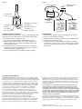
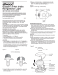
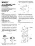
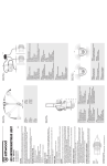
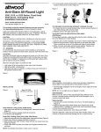
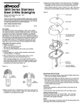
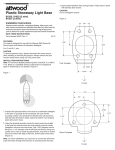
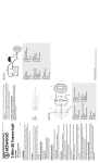
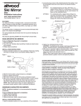
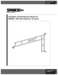
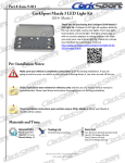
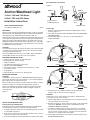
For windshield, on horizontal
3
®
Figure 2
Anchor/Masthead Light
STEP 2
STEP 1
STEP 3
Socket
Axle
12-Volt: 7200 and 7400 Series
24-Volt: 7250 and 7450 Series
Cam-lock Screw
and Oblong Washer
Installation Instructions
SAVE THESE INSTRUCTIONS
Form Number 69394 Rev. B
Vertical
Base
Horizontal
Base
Feed Wires Thru
04-07
FEATURES
Attwood 3-mile (4.8 km) Anchor/Masthead Lights consist of anodized
aluminum poles with lightweight heads. Horizontal and vertical bases
allow light pole to be adjusted and locked within a 180° arc.
Lights provide a 3-mile, 225° forward running light and 2-mile all-round
anchor light. For power-driven boats boats up to 65.6 feet (20 meters).
Lights meet USCG CFR 183.810, ABYC A-16 requirements, and all
applicable standards as tested by Imanna Laboratory, Inc., December
17, 2003. Lights use 8-watt festoon lamp, #9230 (for 12-volt systems)
or #910409 (for 24-volt systems).
Install Light
1. Release cam-lock adjustment handle and adjust light to vertical
position. (Figure 3)
2. Place light in selected position. BE SURE THAT FIN IS ALIGNED
TOWARD STERN.
3. Use provided adaptors, if necessary, to allow installation on
angled windshields.
Figure 3
Fin
(AFT)
CAUTION
To prevent personal injury, disconnect the power source when installing
or servicing any electrical product. Remove vessel from water when
using any 120 VAC power tools.
Lens can be HOT and can melt or scorch fabric. When folded down,
turn light OFF and be sure lens does not touch anything.
REQUIRED FOR INSTALLATION
• Cordless drill; 1/8" and 3/8" (3 and 10mm) bits
• Marine-grade non-silicone sealant
• Phillips screwdriver
• Two #10 pan head stainless steel screws
• 3-position switch (OFF/ON/ON)
• Fuse holder and fuse: 2-amp (for 12-volt systems) or 1-amp
(for 24-volt systems)
• 16-gauge wire
• Marine-grade wire connectors for 16-gauge wire
MOUNTING LOCATION
CAUTION
Install light so that fin (Figure 3) is TOWARD STERN and aligned on
the fore/aft centerline of the vessel (within 1°). If not properly aligned,
lights will not shine in required fore/aft arc.
Base must pivot on the fore/aft centerline and be mounted on a surface
that allows a 360° arc of unobstructed light visibility. (Figure 1)
Bases are available for mounting on vertical or horizontal surfaces.
Release the cam-lock adjustment handle to fold light or adjust to
vertical position.
Figure 1
Locked
Unlocked
Vertical Mount
FWD
AFT
PORT
Fin
(AFT)
STBD
Locked
Unlocked
Horizontal Mount
FWD
AFT
PORT
STBD
4. Using the base as a template, mark the two mounting hole
locations and one wire access hole. (Figure 4)
CAUTION
Position wire access hole carefully, especially on aluminum boats,
so that wires do not contact the hull.
INSTALLATION INSTRUCTIONS
Change Base Type (If Required)
Packaged versions of the Anchor/Masthead Light are shipped with
the vertical base installed. To switch to the horizontal base:
1. Carefully remove the cam-lock screw and oblong washer. Set aside
for reinstallation (Figure 2).
2. Pivot the base axle out of its socket. Note position of the 3 wires in
the base slot. Remove the vertical base.
3. Insert wires through slot of the horizontal base. Install in reverse order.
5. Remove light. Drill two 1/8" (3mm) pilot holes for #10 screws. Drill
one 3/8" (10mm) wire access hole.
6. Bring two 16-gauge (+) wires and one 16-gauge (-) wire up through
access hole. DO NOT connect power to switch until you read
CONNECT POWER TO SWITCH.
7. Use marine-grade waterproof crimp connectors to connect blue
wire to one (+) positive lead from 3-position switch; connect gray
wire to second (+) lead. Connect (-) negative source to black wire
and route to (-) negative terminal on battery.
8. Fasten light to deck with two #10 stainless steel pan head screws.
DO NOT OVERTIGHTEN.
Figure 5
Figure 4
In Line Fuse Holder
(pos)
3-Position Switch
(Off/On/On)
(neg)
Battery
#10 Pan Head
Screw
Black Wire to Ground (-)
1/8" (3mm)
Pilot Hole
Blue Wire (+)
Mast Light (Forward)
3/8" (10mm)
Wire Access Hole
Gray Wire (+)
Anchor Light (Aft)
CONNECT POWER TO SWITCH
Use ONLY the rated voltage. Higher voltage can damage light and
void product warranty. All positive (+) wires must be protected by
fuse (2-amp for 12-volt, 1-amp for 24-volt).
1. Use 3-position, double-pole OFF/ON/ON switch. (Figure 5)
2. From the anchor/masthead light, connect gray wire to one (+)
switch terminal. This switch position should operate all-round
anchor light (both lamps).
3. Connect blue wire to the remaining (+) terminal. This position
should operate forward masthead running light only (one lamp
forward) and all other navigation lights.
4. Test forward running and anchor lights for proper operation.
ATTWOOD LIMITED WARRANTY
ATTWOOD CORPORATION, 1016 North Monroe, Lowell, Michigan 49331
(“Attwood”) warrants to the original consumer purchaser that Attwood brand
products will be free from defects in materials and workmanship under normal
use and service for one year from the date of original consumer purchases.
This limited warranty is not applicable if the product has been damaged by
accident, improper installation, unreasonable or improper use, lack of proper
maintenance, unauthorized repairs or modifications, normal wear and tear,
or other causes not arising out of defects in materials or workmanship.
Attwood products are warranted for use on pleasure boats. Any other
use—including but not limited to commercial, racing, or non-marine
use—are not covered under this warranty. Attwood’s obligation under this
warranty is limited to repair of the product at Attwood’s plant or replacement
of the products at Attwood’s option without expense to the original consumer
purchaser. Any expenses involved in the removal, reinstallation or
transportation of the product are not covered by this warranty.
The product must be returned to Attwood’s plant at the address above,
postage pre-paid, and insured with proof of original purchase including date.
If Attwood is unable to replace the product and repair is not commercially
practical or cannot be timely made, or if the original consumer purchaser is
Black
(To Negative)
Gray (pos-1)
Anchor Forward
(All Around)
Blue (pos-2)
Forward Running
MAINTENANCE
1. To replace lens or lamps, remove top retaining screw and lens.
2. Replace lens with Attwood #912896.
3. Replace lamp(s) with Attwood #9230 (12-volt), #910409 (24-volt).
4. Reinstall lens and retaining screw.
5. To adjust tension on cam-lock adjustment handle: Use Phillips
screwdriver to loosen screw in center of handle (Figure 2). Adjust
tension so handle releases easily, and also holds light in position
when locked.
willing to accept a refund in lieu of repair or replacement, Attwood may refund
the purchase price, less an amount for depreciation. The acceptance by
Attwood of any product returned or any refund provided by Attwood shall not
be deemed an admission that the product is defective or in violation of any
warranty. Products that are replaced or for which a refund is issued become
the property of Attwood.
THIS WARRANTY IS ATTWOOD’S ONLY EXPRESSED WARRANTY OF
THESE PRODUCTS. NO IMPLIED WARRANTY INCLUDING, WITHOUT
LIMITATION, THE IMPLIED WARRANTIES OF MERCHANTABILITY AND
FITNESS FOR A PARTICULAR PURPOSE, SHALL BE EXTENDED BEYOND
THE WARRANTY PERIOD STATED ABOVE FOR EACH PRODUCT. ATTWOOD
SHALL NOT BE LIABLE FOR ANY DAMAGES, FOR LOSS OF USE OF THIS
PRODUCT, NOR FOR ANY OTHER INCIDENTAL OR CONSEQUENTIAL
DAMAGES, COSTS, OR EXPENSES.
Some states do not allow limitations on how long an implied warranty lasts or
the exclusion or limitation of incidental or consequential damages, so the above
limitations and exclusions may not apply to you. This warranty gives you specific
legal rights, and you may have other rights which vary from state to state.
© 2004 Attwood Corporation
1016 N. Monroe Street, Lowell, MI 49331-0260
www.attwoodmarine.com