1
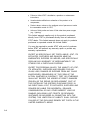
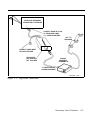
2/12/93
AT&T
®
PagePal
Installation Manual
Copyright 1993, AT&T
All Rights Resewed
Printed in U.S.A.
0II722050-917
Issue 2, February 1993
No Part of this publication may be reproduced in a retrieval system, or transmitted, in any form or by
any means, electronic, mechanical, photocopying, recording, or otherwise, without the prior written
permission of AT&T. The use of trademarks or other designations is for reference purposes only.
NOTICE
Every effort was made to ensure that the information in this manual was complete and accurate at the
time of printing. However, information is subject to change.
COMPATIBILITY
®
The AT&T PagePal is recommended for use with most AT&T telephone systems and commercial
audio amplifiers used for public announcement.
WARRANTY INFORMATION
AT&T provides a limited warranty to this product. Refer to “Warranty Information” in Appendix A.
ORDERING INFORMATION
To order an additional PagePal, use Part Number 722050-917. To order this document, order Part
Number 0II722050-917.
PagePal is a registered trademark of HARRIS CORPORATION Dracon Division.
CENTREX is a registered trademark of AT&T.
The Canadian equivalent of the RJ11C connector is CA11A. Where applicable, CA11A is to be
understood for other references to RJ11 or JR11C in this manual
This product is UL Listed or CSA Certified.
“NOTICE: The Canadian Department of Communications label identifies certified equipment. This certification
means that the equipment meets certain telecommunications network protective operational and safety
requirements. the Department does not guarantee the equipment will operate to the user’s satisfaction.
“Before installing this equipment, users should ensure that it is permissible to be connected to the facilities of the
local telecommunications company. The equipment must al SO be installed using an acceptable method of
connection. In some cases, the company’s inside wiring associated with a singly line individual service may be
extended by means of a certified connector assembly (telephone extension cord). The customer should be aware
that compliance with the above conditions may not prevent degradation of service in some situations.
“Repairs to certified equipment should be made by an authorized Canadian maintenance facility designated by the
supplier. Any repairs or alterations made by the user to this equipment, or equipment malfunctions, may give the
telecommunications company cause to request the user to disconnect the equipment.
“USerS should ensure for their own protection that the electrical ground connections of the power utility, telephone
lines and internal metallic water pipe system, if present, are connected together. This precaution may be particularly
important in rural areas.
Caution: Users should not attempt t O make such connections themselves, should contact the appropriate electric
inspection authority, or electronics, as appropriate.”
VG—2/93—2M
ii
Contents
1
AT&T PagePal System Overview
1-1
■ Description
■ Features
1-2
1-3
Installation
2-1
■ Important Safety Instructions
■ General Information
■ Troubleshooting Guide
2-2
2-4
2-12
A
FCC Regulations and Warranty
A-1
B
AT&T PagePal Functional Diagram
B-1
C
Secondary Circuit Protection
C-1
2
iii
®
AT&T PagePal System Overview
1
AT&T PagePal System Overview
1-1
Descrption
®
The AT&T PagePal unit has been designed to interface most
®
telephone systems (PBX, KTS, Centrex ) to virtually any public
address audio system. In addition, PagePal furnishes inputs for
customer provided background music and auxiliary inputs (such
as an attendant microphone, a radio receiver, recorded
announcements, etc.) Control inputs are provided for tones
generated by PagePal such as pre-announcement tones,
telephone access confirmation, siren, chime, and night bell. All
inputs are automatically selected on a prioritized basis and
routed to a single output which will drive any type of audio
equipment. PagePal can be placed on a desk or shelf, or
mounted to a wall (see installation section).
GS
LEVEL CONTROLS
AT&T
MUSIC
INPUT
ATTENDANT
INPUT
MAIN
OUTPUT
LS
DL
PagePal
Figure 1-1. Front View of the AT&T PagePal
1-2
AT&T PagePal System Overview
SA
®
Features
The AT&T PagePal provides many useful features:
■ Telephone Access from:
–
–
–
Loop Start trunks
Ground Start trunks
Analog Station Lines, PBX or Centrex
Dry Loop page ports (4-wire).
■ Provides a point of clear demarcation between the
telephone system and the audio system
■ FCC registered and UL Listed
■ Main output level control allows adjustment for commercial
power amplifiers or consumer (home Hi-Fi) or specialized
telephone paging amps
■ Level controls to set Attendant Input and Background Music,
relative to telephone level
■ Balanced audio inputs and outputs eliminate hum and noise
pick-up
■ High quality circuitry for low distortion and wide bandwidth
■ Simplified connections via modular telephone jack and
Iugless terminal block
■ Inputs are routed to the output with the following priority
(highest to lowest):
1. Attendant Access for emergency and other important
announcements
2. Alert Tone 1 (siren) for evacuation warning, etc.
3. Telephone Access for general purpose paging
4. Alert Tone 2 (chime) for time clock, door bell, security
alert, etc.
5. Nightbell for incoming, after-hours calls to ring audibly
over the public address system
6. Music input for background music
■ Over-ride or busy tone is returned to the telephone user in
the event of a higher priority
AT&T PagePal System Overview
1-3
■ Call Confirmation and Pre-Announcement tones may be
disabled
■ An optional contact closure output is provided to control
auxiliary equipment (music/page switching, recorder logging,
etc.)
■ Station access mode features:
1. VOX (Voice Operated Switch) controlled off-hook timer
2. Maximum length off-hook timer
3. Responds to forward disconnect (Calling Party
Controlled Disconnect)
4. Dial tone detection and disconnect
5. Open Interval Protection (OIP).
1-4
AT&T PagePal System Overview
Installation
2
Installation
2-1
Important Safety Instructions
When using your telephone equipment, basic safety
precautions should always be followed to reduce the risk of fire,
electric shock and injury to persons, including the following:
1. Read and understand all instructions.
2. Follow all warnings and instructions marked on the
product.
3. Unplug this product from the wall outlet before cleaning.
Do not use liquid cleaners or aerosol cleaners. Use a
damp cloth for cleaning.
4. Do not use this product near water, for example, near a
bath tub, wash bowl, kitchen sink, or laundry tub, in a
wet basement, or near a swimming pool.
5. Do not place this product on an unstable cart, stand, or
table. The product may fall, causing serious damage to
the product.
6. Slots and openings in the cabinet and the back or
bottom are provided for ventilation, to protect the product
from overheating. These openings must not be blocked
or covered. The openings should never be blocked by
placing the product on the bed, sofa, rug, or other similar
surface. This product should never be placed near or
over a radiator or heat register. This product should not
be placed in a built-in installation unless proper
ventilation is provided.
7. This product should be operated only from the type of
power source indicated on the marking label. If you are
not sure of the type of power supply to your building,
consult your dealer or local power company.
2-2
Installation
8.
WARNING: RISK OF ELECTRICAL SHOCK —
EQUIPMENT MUST BE PROPERLY GROUNDED.
Your Harris equipment requires a properly grounded
three-prong power receptacle for safe operation. Have
the receptacle checked by a qualified electrician before connecting this equipment. Do not cut or remove
the third (ground) prong from the power transformer.
Do not use two-prong extension cords or adapters to
defeat the safety features of this equipment. If you
have a two-prong receptacle, it must be replaced with
a three-prong receptacle, installed by a qualified electrician.
9. Do not allow anything to rest on the power cord. Do not
locate this product where the cord will be abused by
persons walking on it.
10. Do not overload wall outlets and extension cords as this
can result in the risk of fire or electric shock.
11. Never push objects of any kind into this product through
cabinet slots as they may touch dangerous voltage
points or short out parts that could result in a risk of fire
or electric shock. Never spill liquid of any kind on the
product.
12. To reduce the risk of electric shock, do not disassemble
this product, but take it to a qualified serviceman when
service or repair work is required. Opening or removing
covers may expose you to dangerous voltages or other
risks. Incorrect reassembly can cause electric shock
when the appliance is subsequently used.
13. Unplug this product from the wall outlet and refer
servicing to qualified service personnel under the
following conditions:
A. When the power supply cord or plug is damaged or
frayed.
B. If liquid has been spilled into the product.
Installation
2-3
C. If the product has been exposed to rain or water.
D. If the product does not operate normally by following
the operating instructions. Adjust only those controls
that are covered by the operating instructions.
Improper adjustment of other controls may result in
damage and will often require extensive work by a
qualified technician to restore the product to normal
operation.
E. If the product has been dropped or the cabinet has
been damaged.
F . If the product exhibits a distinct change in
performance.
14. Avoid using a telephone (other than a cordless type)
during an electrical storm. There may be a remote risk of
electric shock from lightning.
15. Do not use the telephone to report a gas leak in the
vicinity of the leak.
SAVE THESE INSTRUCTIONS.
General Information
Please adhere to the following precautions:
1. Never install telephone wiring during a lightning storm.
2. Never install telephone jacks in wet locations unless the
jack is specifically designed for wet locations.
3. Never touch uninsulated telephone wires or terminals
unless the telephone line has been disconnected at the
network interface.
4. Use caution when installing or modifying telephone lines.
2-4
Installation
Recorder Logging
A tape recording may be desirable for evidence to prove
that certain announcements or warnings were made over
the paging system. The normally open contacts
(terminals 16 & 17, see Figure 2-1) may be used to
activate a tape recorder to record all tones and
announcements that were made, without the background
music in between which would consume large amounts
of tape.
Balanced to Unbalanced
The balanced inputs of the AT&T PagePal may be
driven by an unbalanced source. Simply connect the two
wires to the + and – input terminals.
Unbalanced inputs to power amplifiers may be driven
from the PagePal’s balanced output by connecting the
PagePal ground (terminal 14, see Figure 2-1) to the
input ground of the power amp, and the + or – output
(terminal 13 and 15, see Figure 2-1) of PagePal to the
“hot” input pin of the power amp. However, the output
level will be 6dB less.
Connections
The PagePal provides four connectors on the unit’s back panel
(see Figure 2-1). The following information describes each of
the connectors and their function.
Modular Telephone
Jack
This is a standard 6-pin telephone Modular type connector,
located at J1 on the unit back panel. See Table 2-1 for a
description of each of the pins.
Installation
2-5
MICROPHONE
TO LOUDSPEAKERS
PREAMP
MUSIC SOURCE
PUBLIC ADDRESS
AUDIO SYSTEM
RECORDED
ANNOUNCEMENTS
TYPICAL
INPUTS
RADIO RECEIVER
POWER AMPLIFIER(S)
SIGNAL PROCESSING
CONTROL
CLOSE FOR
ATTENDANT ACCESS
STATION OR KEY
TELEPHONE SYSTEM,
PRE-PROGRAMMED
FOR NIGHT BELL
PHONE SYSTEM
TO AC
OUTLET
PAGEPAL
Figure 2-1. Typical Connections to the AT&T PagePal Connectors (Rear Panel View)
2-6
Installation
Table 2-1. AT&T PagePal J1 Modular Telephone Jack
Pin
Number
Description
1
Not Used.
2
C1 control input for Dry Loop (Page Port) activation by
closure (may also be used for Ground Start grounding
point).
3
Ring (– polarity is important for Ground Start).
4
Tip (+ polarity is important for Ground Start).
5
C control input for Dry Loop (Page Port) activation by
contact closure.
6
Not Used.
Terminal Block
Connector
This is a 20 Pin lug less-type terminal block located at J2 (see
Figure 2-1). See Table 2-2 for a contact descriptions.
Factory Test Connector
Wall Plug Transformer
J3 - No user connections
-115 VAC, 60 Hz. — U.L. Listed.
Installation
2-7
Table 2-2. AT&T PagePal J2 Terminal Block Connector
Terminal
2-8
Description
1
Ground for ground start ground/Common connection for terminals 2-6.
2
Close a contact between this terminal and J2-1 to activate Attendant Access.
3
Close a contact between this terminal and J2-1 to active TONE 1.
4
Close a contact between this terminal and J2-1 to activate TONE 2.
5
Connect a jumper between this terminal and J2-1 to disable confirmation and
pre-announcement tones.
6
Connect a jumper between this terminal and J2-1 to disable the pre-announcement tone.
7
Attendant input, + phase of balanced 600 ohm input.
8
Ground for optional shield termination of Attendant Input.
9
Attendant Input, – phase of balanced 600 ohm input.
10
Music Input, + phase of balanced 100 Kohm input.
11
Ground for optional shield termination of Music Input.
12
Music Input, – phase of balance 100 Kohm input.
13
Audio Output to paging system, + phase of balanced output, 300 ohm.
14
Ground for optional shield termination of output.
15
Audio Output to paging system, – phase of balanced output, 300 ohm.
16
Normally open contact (with J2-17) that may be used to activate paging equipment.
17
Normally open contact (with J2-16). Contact is closed when any input with priority higher
than music is present.
18
Night bell Input from Key systems. Night bell is activated by any low voltage greater than
10V AC/DC.
19
Common terminal for night bell input voltage. (Tip)
20
Night bell input from ringer voltage. REN=0.5, Type B. (Ring). In Canada: DOC Load
Number = 22.
Installation
Wall Mount Instructions
1. Determine where the desired wall mounting location
should be.
2. Drive the screw into the wall, leaving 3/16'' space
between the wall and the bottom of the screw head (see
Figure 2-2).
3. Mount the PagePal keyhole slot over the screw head.
Adjust the screw depth so that the rubber feet seat firmly
against the wall.
4. Temporarily remove the PagePal while attaching wiring
to the terminal block.
PAGEPAL
PAGEPAL
MOUNTING
HOLE
3/16''
WALL
SURFACE
Figure 2-2. Wall Mounting
Installation
2-9
Adjustments
Slide Switch
This four-position switch is provided to configure the AT&T
PagePal for the appropriate mode of telephone access. See
Figure 1-1.
LS-Loop Start
PBX trunk or a dedicated phone set
Note: With the switch in this position, the PagePal is optioned
to interface with a Loop Start trunk of a PBX or Line Port of
Key System. In this mode, the PagePal supplies the “talk
battery” on Tip and Ring.
GS-Ground Start
PBX ground start trunk
Note: With the switch in this position, the PagePal is optioned
to interface with a Ground Start trunk of a PBX. in this mode it
is imperative that the PBX ground be connected to Pin 1 of the
20 pin connector on the PagePal or pin 2 of the RJ11 connector on the PagePal. In addition, the PagePal supplies the “talk
battery” on Tip and Ring after the PBX has supplied a “hand
shake” to the PagePal by momentarily grounding the Ring lead.
NOTE: PagePal must be connected to CWP ground at J2-1.
SA-Station Access
PBX station line or Central Office
subscriber line
Note: With the switch in this position, the PagePal is optioned
to interface with a CENTREX, PBX or Key System ANALOG
station. In this mode the PagePal wants to receive “talk battery”
and ring voltage from the host system that it is connected to.
DL-Dry Loop
PBX page ports or auxiliary pac
Note: With the Switch in this position, the PagePal is optioned
to interface with the Page Port of a Key System or an Auxiliary
Pac of a PBX. Dry Loop is a 4 wire connection, pins 2 and 5 of
the RJ11 are intended to interface with the control leads of the
host system, while Tip and Ring connect to the usual pins 3
and 4 of the RJ11. In this mode the PagePal will not have “talk
battery” on its Tip and Ring and will not expect to see “talk
battery” on the host systems Tip and Ring.
2-10
Installation
Level Controls
Main Output
Adjusts level of output. Full counter-clockwise rotation provides
unity gain from Telephone input to PagePal output. This is best
for driving AT&T PagePals, or consumer (home Hi-Fi) type
amplifiers.
Full clockwise rotation provides 14dB gain.* This will be more
appropriate commercial-industrial sound equipment. Refer to
the specifications of your power amplifier for the appropriate
input level, or experiment with the adjustments for best results.
Set the Main Output level first using telephone input, then
adjust Attendant and Music inputs for an appropriate relative
level. (Telephone input signals are typically -15 to -10dBm.)
Attendant Input
Adjusts level of Attendant Input relative to the Telephone Input.
Adjustment range is from 0dB to less than -30dB.
Music Input
Adjusts the level of Music Input relative to Telephone Input.
Adjustment range is from 0dB to less than -30dB.
*Gain assumes that the balanced output is driving 600 ohms. (See block diagram in Appendix B for gain
structure.)
Installation
2-11
Troubleshooting
Use Table 2-3 to assist in locating possible problems.
Table 2-3. AT&T PagePal Troubleshooting Suggestions
Problem
Troubleshooting Steps
Solution
Green LED flashes.
The LED flashes approximately
two times per second when the
unit is operating normally.
No action required.
Green LED glows steady.
This indicates that the control
logic is re-setting itself. Unplug
the unit for five seconds, then
plug it in again. This will re-start
the unit.
If LED still glows steady, return
the unit for repair.
No music source connected to the
input, but there is noise on the
output in the music mode.
Turn the Music Input volume
control to the full counter
clockwise position.
Leave the volume control turned
down if no music source is to be
used.
Hum, buzz or noise on the output
in the music mode with a music
source connected in a unbalanced
configuration.
Using a piece of wire, short the
un-used music input pin to pin
11 of J2.
If the problem is fixed, leave the
pins connected.
No music on the output with a
music source connected to the
input.
Check the volume control level.
Adjust as needed.
A higher priority in the PagePal
is active.
Verify and correct if needed.
Check the input and output
connections.
Verify and correct if needed.
2-12
Installation
Table 2-3. AT&T PagePal Troubleshooting Suggestions (continued)
Problem
Night Bell is not active when it is
intended to be activated with a
low AC or DC voltage.
Night Bell is not active when it is
intended to be activated with a
Ring voltage.
Alert Tone 2 is not functioning.
Troubleshooting Steps
Solution
The input voltage level is too
low or missing.
Must be greater than 10 VAC or
VDC.
Make sure that the input
connections are to pins 18 and
19 of J2 (polarity is important).
Verify and correct if needed.
A higher priority in the PagePal
is active.
Verify and correct if needed.
Check the MAIN OUTPUT
volume control setting.
Correct if needed.
The input voltage level is too
low or missing.
Must be greater than 40 VAC
Make sure that the input
connections are to pins 19 and
20 of J2.
Correct if needed.
A higher priority in the PagePal
is active.
Verify and correct if needed.
Check the MAIN OUTPUT
volume control setting.
Correct if needed.
Check the connection to the
back panel, pins 1 and 4 of J2.
Correct if needed.
Check the MAIN OUTPUT
volume control setting.
Correct if needed.
Verify using an Ohm meter that
a contact closure is being provided from the host equipment.
Correct if needed.
A higher priority in the PagePal
is active.
Verify and correct if needed.
Installation
2-13
Table 2-3. PagePal Troubleshooting Suggestions (continued)
Problem
Troubleshooting Steps
Solution
Relay chatter when Tip and Ring
is connected to the PagePal.
Verify that the Telephone
Access Switch is in the proper
position for the application.
Change the Telephone Access
Switch to the appropriate
position.
When using the PagePal in the
Page Port mode a busy tone is
returned when attempting to
access the PagePal.
Verify that the Telephone
Access Switch is in the proper
position for the application.
Change the Telephone Access
Switch to the DL position.
Verify that Attendant Access is
not active.
Wait for the Attendant Access to
de-activate.
Verify that the host telephone
system’s ground is connected to
Pin 1 of J2 on the PagePal or
Pin 2 or the RJ-11 jack.
Connect the ground.
Verify that the Telephone
Access Switch is in the proper
position for the application.
Change the Telephone Access
Switch to the GS position.
Tip and Ring may be reversed
(the Ring is always more
negative than the Tip).
If reversed, swap Tip and Ring.
Excessive loop length.
Must be less than 1200 ohms.
The PagePal answers a station
call, then immediately hangs up.
Verify that the Telephone
Access Switch is in the proper
position for the application
(SA not GS).
Change the Telephone Access
Switch to the SA position.
Dial tone or confirmation tone is
sent to the speaker when the
PagePal has not been accessed.
The Telephone Access Switch’s
position may have been
changed while the Tip and Ring
was connected.
Remove the Tip and Ring
connection. Verify what mode of
operation is desired. Change
the Telephone Access Switch to
the proper position. Re-install
Tip and Ring.
The PagePal is not being accessed
in the Ground Start mode.
2-14
Installation
Table 2-3. AT&T PagePal Troubleshooting Suggestions (continued)
Problem
Troubleshooting Steps
Dry loop (Page Port) mode won’t
access PagePal.
Pins 2 and 5 of the RJ11
connector must be closed by a
contact in the PBX when access
is desired.
Verify that this connection is
made.
Alert Tone 1 is not functioning.
Check the connection to the
back panel, pins 1 and 3 of J2.
Correct if needed.
Check the MAIN OUTPUT
volume control setting.
Correct if needed.
Verify using an Ohm meter that
a contact closure is being provided from the host equipment.
Correct if needed.
A higher priority in the PagePal
is active.
Verify and correct
if needed.
Check the connection to the
back panel, pins 1 and 2 of J2.
Correct if needed.
Check the MAIN OUTPUT
volume control setting.
Correct if needed.
Check the ATTENDANT INPUT
volume control setting.
Correct if needed.
Verify using an Ohm meter that
a contact closure is being provided from the host equipment.
Verify and correct if needed.
Turn the Attendant Input volume
control to the full counter
clockwise position.
Leave the volume control turned
down if no Attendant Access
source is to be used.
Attendant Access is not
functioning.
No Attendant Access source
connected to the input, but there
is noise on the output in the
Attendant Access mode.
Solution
Installation 2-15
Table 2-3. AT&T PagePal Troubleshooting Suggestions (continued)
Problem
Troubleshooting Steps
Solution
Hum, buzz or noise on the output
in the Attendant Access mode
with a Attendant Access source
connected in a unbalanced
configuration.
Using a piece of wire, short the
un-used Attendant Access input
pin to pin 8 of J2.
If the problem is fixed, leave the
pins connected.
No pre-announce tone is sent to
the output, but it is desired.
A jumper has been installed on
pins 1 and 6 of J2.
Remove the jumper.
No pre-announce or confirmation tone is sent to the output or
the telephone, but it is desired.
A jumper has been installed on
pins 1 and 5 of J2.
Remove the jumper.
No power LED.
Using a Voltmeter, check for AC
Voltage at the wall outlet.
Correct facilities problem.
Bad wall plug-in power supply
on the PagePal.
Return the PagePal to the
proper location for repair.
Adjust gain controls.
Adjust as needed.
The wrong impedance is
attached to the output.
Ideally the PagePal would like
to drive a 600 Ohm impedance,
however by using the Main
Output volume control, various
impedances can be used.
Low Volume on the output.
2-16
Installation
Appendix A—FCC Regulations and Warranty
FCC Regulations—Part 15
Radio Frequency
Interference
The AT&T PagePal generates and uses radio frequency energy
and if not installed and used in strict accordance with the
manufacturer’s instructions, may cause interference to radio
and television reception. Testing has been conducted for
compliance with the limits for Class B device in accordance
with the specifications in Subpart J of Part 15 of the FCC
Rules. This testing is designed to provide reasonable protection
against such interference. However, there is no guarantee that
interference will not occur in a particular installation. If this
equipment does cause interference to radio or television
reception, which can be determined by turning the unit off and
on, the user is encouraged to try to correct the interference by
one or more of the following measures:
●
●
Reorient the radio or TV receiving antenna.
Relocate the PagePac 6 Plus with respect to the radio or TV
receiver or vice-versa.
●
Plug the PagePac 6 Plus into a different outlet so that it and the
radio or TV receiver are on different branch circuits.
●
If necessary, the user should consult the dealer or an experienced
radio/television technician for additional suggestions. The user may
find the following booklet, “How To Identify and Resolve Radio-TV
Interference Problems,” helpful. This booklet was prepared by the
Federal Government Printing Office, Washington, DC 20402. Stock
order No. 004-000-00345-4.
A-1
FCC Regulations—Part 68
This equipment is registered with the Federal Communications
Commission (FCC) in accordance with Part 68 of its Rules. The
FCC requires that the manufacturer provide you with the
following information:
1. Connection and Use with Nationwide Telephone Network
The FCC requires that you connect your telephone equipment
to the nationwide telephone network through a modular
telephone outlet or jack. The modular telephone outlet or jack
to which the equipment must be connected is a USOC RJ11C.
Registered equipment may not be used with Coin Telephone
Lines. Equipment may be used with Party Lines in areas where
state tariffs permit such connections and when equipment is
adaptable for such use.
2. Information You May Need to Supply the Telephone
Company
Upon request of your local telephone company, you are
required to provide them with the following information:
A. The lines to which you will connect the telephone
equipment.
B. The FCC registration number and Ringer Equivalence
Number (REN). Both numbers are listed on the equipment
label. The REN is useful to determine how many devices you
may connect to your telephone line and still have them ring
when your telephone line is called. In most, but not all, areas,
the sum of all RENs per line should be 5 or less. You may
want to contact your local telephone company. The local
telephone company must also be notified upon final
disconnection of the equipment from the local telephone
company lines.
A-2
●
Failure to follow AT&T's installation, operation or maintenance
instructions;
●
Unauthorized modification or alteration of the product or its
components;
●
Product abuse, misuse or the negligent acts of persons not under
the reasonable control of AT&T;
●
Actions of third parties and acts of God other than power surges
(e.g., lightning).
This limited warranty applies only to the product purchased
directly from AT&T or purchased directly from an authorized
AT&T dealer. This limited warranty does not apply to products
purchased or operated outside the United States.
You may be required to provide AT&T with proof of purchase
before AT&T will perform any warranty repair or provide any
warranty replacements.
EXCEPT AS SPECIFICALLY SET FORTH ABOVE, AT&T, ITS
AFFILIATES, SUPPLIERS AND DEALERS MAKE NO
WARRANTIES, EXPRESS OR IMPLIED, AND SPECIFICALLY
DISCLAIM ANY WARRANTY OF MERCHANTABILITY OR
FITNESS FOR A PARTICULAR PURPOSE.
EXCEPT FOR PERSONAL INJURY, THE LIABILITY OF AT&T,
ITS AFFILIATES, SUPPLIERS AND DEALERS FOR ANY
CLAIM, LOSS, DAMAGE OR EXPENSE FROM ANY CAUSE
WHATSOEVER, REGARDLESS OF THE FORM OF THE
ACTION, WHETHER IN CONTRACT, TORT OR OTHERWISE,
SHALL NOT EXCEED THE LESSER OF DIRECT DAMAGES
PROVEN OR THE REPAIR OR REPLACEMENT COST OF
THE SYSTEM OR THE SYSTEM’S PURCHASE PRICE. IN
NO EVENT SHALL AT&T, ITS AFFILIATES, SUPPLIERS AND
DEALERS BE LIABLE FOR INCIDENTAL, RELIANCE,
CONSEQUENTIAL OR ANY OTHER INDIRECT LOSS OR
DAMAGE (INCLUDING LOST PROFITS OR REVENUES
SUSTAINED OR INCURRED IN CONNECTION WITH THE
SYSTEM). THIS LIMITATION OF LIABILITY SHALL SURVIVE
FAILURE OF THE EXCLUSIVE REMEDY SET FORTH IN THE
LIMITED WARRANTY ABOVE.
A-4
In Canada, the DOC registration number and Load Number
appear on the maple-leaf label, and the Load Number is under
the maple-leaf label.
Warranty Information
Limited Warranty and Limitation of Liability
AT&T warrants to you that the product will be free from defects
in material and workmanship when title passes to you. If you
notify AT&T that the product has failed to operate as warranted
within one year of the date title passes to you, AT&T will, at its
option, repair or replace the component or components of the
product that failed to operate as warranted. Any repair or
replacement components may be new or refurbished and will
be provided on an exchange basis. If AT&T determines that the
product cannot be replaced, AT&T will refund the purchase
price to you.
If you purchased the product directly from AT&T, AT&T will
perform warranty repair on your premises in accordance with
the terms and conditions of AT&T’s “Business Day” or
“Around-the-Clock” warranty plans. The details of AT&T’s
warranty plans may be obtained from AT&T. If you purchased
the product from an authorized dealer, you will be covered by
AT&T’s authorized dealer warranty plan during the warranty
period. Contact your authorized dealer for details of AT&T’s
authorized dealer warranty plan. AT&T’s obligation to repair,
replace or refund as set forth above is your exclusive
remedy.
The limited warranties provided above do not cover damages,
defects, malfunctions or product failures caused by:
A-3
Installation and Maintenance Information
There are several types of installation and maintenance plans
available from AT&T and/or your dealer. Please call your AT&T
sales representative or authorized dealer for details.
For warranty service, contact your AT&T representative or
authorized dealer.
A-5
Appendix B—AT&T PagePal Functional Diagram
PAGING EQUIPMENT INTERFACE
(PagePal)
I
I
DRY LINE LEVEL INPUT WITH
I
I
CONTACT CLOSURE FROM
P1 CONTACTS
AMPLIFIED MIC, RECORDED I
I
ANNOUNCEMENTS, RADIO,
P1
I
I
ATTENDANT INPUT LEVEL
ETC.
600 OHM 0dB
I
I
I
I
P6
I
I
MUSIC INPUT LEVEL
100K OHM 0dB
MUSIC SOURCE
I
I
I
I
300 OHMS
I OUTPUT TO
I
20dB
TELEPHONE INTERFACE
I POWER AMP(s)
I
300 OHMS
TIP
I
I
RING
P3
I
I
CLOSED @ P1 THROUGH P5
I
I
REMOTE AMP
C
I CONTROL
I
C1
I
I
I
I
I
I TONE 1
CONTACT CLOSURE
TONE GEN
P2, 4, or 5
TONE 2
I
I OPTION JUMPERS
CONTACT CLOSURE
CONTACT CLOSURE
NIGHT
BELL
I
I RING DETECT
POWER SUPPLY
& OTHER TONES
I 115 VAC
NIGHT SELL
I AC/DC DETECT
I
I
I— — — — — — — — — — — — — — — — — — — — — — — — — — — — — — I
—————————————————————————————————
LOOP START or GROUND START
-24VDC TALK BATTERY
STATION or CENTREX
VOX TIMEOUT
MAX. TIMEOUT
DRY LOOP (PAGE PORT)
Figure B-1. AT&T PagePal Functional Diagram
B-1
Appendix C—Secondary Circuit Protection
Important Information
This equipment is for use on telephone wiring containing a
secondary circuit protector. This paging equipment requires
a Harris Dracon model 22060-930 PageGuard Secondary
Circuit Protector where applicable (see Figure C-1).
Each PagePac unit is supplied with a PageGuard protector
factory-installed on the principal Tip-Ring pair. Each terminal
pair on Terminal Strip “B” (see Figure C-2 of the PagePac
manual) that is to be connected to any wires that go off
premises must be supplied with an additional PageGuard
protector.
The secondary circuit protector must be located between the
primary protector and the paging equipment. Refer to the
Safety Information and Installation Steps below.
Safety Information
■ The PageGuard is used when connecting paging equipment
directly to telephone lines that maybe exposed to high
voltage power lines.
■ Never install telephone wiring during a lightning storm.
■ Never install telephone jacks in wet locations unless the
jack is specifically designed for wet locations.
■ Never touch uninsulated telephone wires or terminals unless
the telephone line has been disconnected at the network
interface.
■ Use caution when installing or modifying telephone lines.
Secondary Circuit Protection
C-1
PROVIDED
BY
TELCO
TELCO
DEMARCATION
MAIN BUILDING
A
B
BUILDING #2
PAGING
EQUIP.
B
A
A
B
PAGING
EQUIP.
PAGING
EQUIP.
CO LINES
PROVIDED
BY
TELCO
PROTECTION LOCATIONS
A = PRIMARY CIRCUIT PROTECTOR
B = SECONDARY CIRCUIT PROTECTOR
U.L. SPECS
497
497A
Figure C-1. Example Configurations Requiring Secondary Protection When Paging Equipment is
Connected Directly to the Telephone Network
Installation Steps
Save these instructions.
1. Connect the green wire on PageGuard to earth ground.
To un-install the PageGuard
reverse order of these steps.
2. Plug a modular connector from the paging equipment
telephone line interface to the modular connector on the
PageGuard.
3. Install the PageGuard modular plug to the C.O.
telephone lines (see Figure C-2).
C-2
Secondary Circuit Protection
TELEPHONE EQUIPMENT
CONNECTED TO NETWORK
CONNECT MODULAR PLUG
TO TELEPHONE LINES
(i.e., PBX/KTS/CENTREX)
OUT TO
SPEAKERS
CONNECT GREEN WIRE
TO EARTH GROUND
PAGEGUARD
(P/N 22060-930)
NOT INCLUDED
PAGING
EQUIPMENT
(POWERMATE)
TO INPUT SIDE OF
PAGING EQUIPMENT
PGEGRD.DRW
10/22/91
Figure C-2. PageGuard Installation
Secondary Circuit Protection
C-3
SELECT CODE 468-248-101
©1993 AT&T
All Rights Reserved
Printed in U.S.A.
0II722050-917
Issue 2, February 1993
Graphics © AT&T 1988