1
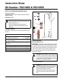
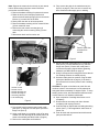
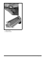
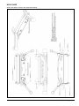
Date: August 21, 2012
No. B-2093
Service Bulletin
Ariens Company
655 W. Ryan St.
Brillion, WI 54110
www.gravely.com
Product Family: Pro-Turn 400 Mowers
Subject: Possible Foot Plate Weld Fracture
Dealer Action: Inspect and Install Kit
Model
Serial Number Range
Description
992230
101 – 177, 179 – 181, 183 – 184, 186 – 187, 192 – 196, 198 – 205,
208 – 223, 225, 227 – 229, 231 – 233
Pro-Turn 452
992231
101 – 111, 114 – 118, 121 – 122, 124 – 125, 130, 136, 138 – 140, 143 – 144,
146 – 147, 150 – 151, 156, 159, 161, 167, 169, 173, 175, 180, 183, 185, 187
Pro-Turn 452
992232
101 – 109, 111 – 120, 122 – 128, 130 – 139, 141 – 142, 144, 147, 152, 154,
156 – 157, 159, 171 – 174, 183 – 184, 196 – 197, 199 – 200, 204
Pro-Turn 460
992233
101 – 266, 268 – 284, 286 – 371
Pro-Turn 460
992234
101 – 181, 183, 186 – 198, 200 – 202, 204 – 243,246 – 249, 255, 258 – 261,
263 – 265,267, 269, 271, 275 – 287, 290 – 291, 293 – 299, 302 – 303,
310 – 312, 314 – 317, 322 – 325, 327 – 328, 333, 335, 342, 345,
354 – 355,361, 368, 370 – 373, 377, 380, 383 – 384, 386, 388 – 389,
392 – 397,400 – 404, 406, 409, 412
Pro-Turn 460
992235
101 – 874
Pro-Turn 460
992238
101 – 124, 126 – 162, 164 – 166
Pro-Turn 466
992239
101 – 292, 294, 296 – 300, 302 – 308, 314 – 316, 318, 501 – 504, 506 – 508,
510 – 514, 517 – 520, 522 – 524, 526 – 527, 529
Pro-Turn 472
Ariens Company has received a limited number of reports of fractured welds on the foot plate of the
Gravely Pro-Turn 400 series commercial mowers in the model and serial number ranges listed above. The
foot plate is not a structural component of the frame, so this crack will not affect the structural integrity of
the machine. However, the fractured welds are cosmetically unpleasing and over time the foot plate may
come loose due to vibration.
To address this issue, Ariens Company has developed two cradle plates kits:
•
•
59214800 (52", 60" and 66" models)
59214900 (72" models).
The cradle plates in these kits stiffen the foot plate mounting area of the machine to prevent cracks from
developing at the welds. The kits include the cradle plates along with other supplies needed to install the
plates. Because welding will be required, primer and touch up paint are included. Attached is an installation
instruction sheet for the kits.
Page 1 of 2
Date: August 21, 2012
No. B-2093
Please note the following important items:
•
•
•
•
•
•
All PT400 models shipped from Ariens Company after 7/23/2012 have been manufactured with the
cradle plates installed on the frame below the foot plate.
All unsold dealer inventory is to be updated with 59214800 or 59214900 prior to sale.
A certified welder should be used to do the welding portion of the repair.
All registered owners of Pro-Turn 400 units will be contacted by letter from Ariens Company about this
issue. Customers will be made aware that the foot plate weld may fracture and instructed to contact
their dealer if the problem occurs.
Normal warranty applies. Flat rate for installation of 59214800 and 59214900 is 3.0 hours.
The installation of kits 59214800 or 59214900 on a Pro-Turn 400 unit with an 892040 bagger installed
will require changing the front weight bracket p/n 03969351 to p/n 04555851 to provide additional
clearance for the cradle plate. Refer to Service Bulletin B-2094 for more information about this change.
Page 2 of 2
Instruction Sheet
Kit Number: 59214800 & 59214900
FOOT PLATE REPAIR INSTRUCTIONS
For use on models:
59214800: 992230, 992231, 992232, 992233, 992234,
992235, 992238
4
3
59214900: 992239
1
2
WARNING: FAILURE TO FOLLOW
INSTRUCTIONS could result in personal injury
and/or damage to unit.
5
Read, understand, and follow all safety
practices in Owner/Operator Manual before
beginning.
6
Package Contents
Check the contents of your kit for the parts listed below
(Figure 1):
Item
Description
Qty Ariens P/N
1 Cradle Plate (52, 60, 66" Decks)
Cradle Plate (72" Decks)
1
04554353
1
04554453
2
1/2"-13 x 1 1/4" Round Head
Square Neck Bolt
2
06224700
3
9/16" x 1 3/8" x 7/64" Flat Steel
Washer
2
06442000
4 1/2"-13 Locking Nylon Flange Nut
2
06500010
5
Gravely Red Spray Paint
1
00008700
6
Gravely Red Touch-up Paint
1
00026600
7
20 oz. Galvanizing Primer
1
00077800
7
Figure 1
INSTALLATION
Remove Mower Deck
IMPORTANT: If desired the mower deck does not need
to be completely removed. If this repair method is chosen
the PTO belt is removed, the rear mounting pins are left
in place and the deck allowed to pivot down as the front
of the tractor is lifted. If deck remains attached to the
tractor a welding blanket must be used to protect the
deck during welding.
CAUTION: AVOID INJURY. Prior to lifting unit
for repair, ensure that jack stands are strong,
secure and will support the weight of the unit
and mechanic. Follow all safety precautions in
the unit’s owner/operator manual.
1. Remove PTO belt.
WARNING: AVOID INJURY. Mower lift arms
and mower lift pedal could cause severe injury
if the lift assist spring is not disconnected
before disconnecting the lift links.
Springs store energy. Keep body parts well
away from pinch points when removing the
deck.
© Copyright 2012 • Ariens Company • Brillion, WI 54110
08400165A 8/12 Page 1 of 4
Note: Support the mower deck on blocks or jack stands
before disconnecting links from mower lift arms to
prevent the deck from falling.
12. Fully remove the paint in the marked areas (see
figure 3 on page 2). Take care not to remove any
steel. Clean area thoroughly prior to welding.
2. Remove hardware retaining foot plate and remove.
3. Raise the deck to the transport position and
disconnect the lift assist springs (6) from the mower
lift arms (1) on each side of the deck.
4. Slowly lower the deck to its lowest position.
5. Remove hardware retaining all four mower lift links
(2) from mower lift arms.
6. Remove the rear mower mounting pins (4)
connecting the mower mounting arms (3) to the
deck.
7. Slide mower deck out from under unit.
6
Remove paint from
all areas to be
welded.
Figure 3
2
13. Mount and install cradle plate (item 1) using two 1/2
bolts (item 2), two flat washers (item 3), and two
flange nuts (item 4). Ensure that cradle plate is
centered and properly aligned before tightening
hardware (see Weld Guide on page 4).
1
5
4
14. Using C-clamps and/or locking pliers ensure that all
four welding surfaces are mated properly.
15. Weld the cradle plate into position using the weld
guide (see Weld Guide on page 4). If the deck is
still mounted to the tractor protect it with a welding
blanket.
3
1. Mower Lift Arm
2. Mower Lift Link
3. Mower Mounting Arm
4. Mower Mounting Pin
5. Mounting Hardware
6. Lift Assist Spring
Figure 2
CAUTION: The paint on the frame can catch fire and
continue to burn if it becomes too hot. Be prepared to
extinguish flame immediately if it begins to burn. To keep
welding zones cooler, alternate between different areas
or allow frame to cool between weld beads.
16. Upon completion of welding allow frame to cool
completely.
8. Remove front right and left lift arms.
17. Dress welds as necessary and clean all areas
completely with isopropyl alcohol.
9. From below front foot plate loosely install cradle
plate (item 1) using two 1/2 bolts (item 2) and two
flange nuts (item 4).
18. Coat all welds an unprotected steel with galvanizing
primer (item 7). Follow application instructions on
primer can.
10. Using cradle plate as a template, mark off an area
at least 3/4" from the edge of the cradle plate in all
areas to be welded (see Weld Guide on page 4).
19. Coat all welds and unprotected steel with enamel
paint provided with kit.
11. Remove the cradle plate and hardware.
08400165A 8/12 Page 2 of 4
Figure 4
20. Reinstall deck and adjust per procedure found in
owner’s manual.
21. Reinstall foot plate.
08400165A 8/12 Page 3 of 4
WELD GUIDE
Weld cradle plate to frame in the areas shown below.
08400165A 8/12 Page 4 of 4