1
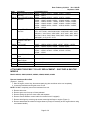
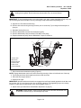
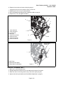
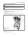
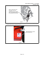
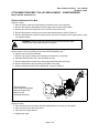
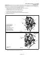
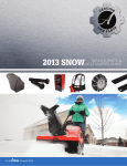
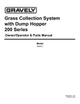
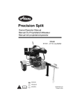
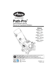
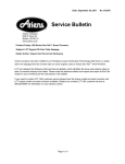
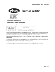
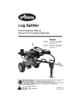
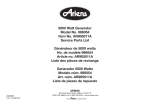
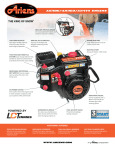
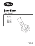
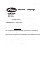
Date: February 26, 2014 No. C-2014R
Replaces C-2014
Service Campaign
Ariens Company
655 W. Ryan St.
Brillion, WI 54110
www.ariens.com
Product Family: Ariens Compact Sno-Thro, Ariens Compact Track Sno-Thro, Sno-Tek,
Ariens PB-28, Gravely PB- 28
Subject: Important Product Safety Recall
Dealer Action: STOP SALE – Repair Immediately
Ariens Company has identified a potential safety concern on models and serials listed in the table below.
The auger drive pulley, #00268951, may develop a crack which could affect the brake's ability to stop the
auger/impeller, resulting in an unsafe condition.
Dealers are instructed to Stop Sale Immediately of any unsold inventory which falls into the model and
serial ranges listed. Additionally, dealers are asked to contact consumers who purchased affected
machines from your dealership to coordinate repair of those machines as soon as possible. Ariens
Company is sending a letter to registered owners of all affected machines alerting them to this situation.
Ariens Company has been reworking product since this issue was identified, and all machines which have
been reworked by Ariens Company will have a black check mark on the carton label as well as the model/
serial label on the machine.
Dealers are asked to order kit #52001800 and install it on each affected unit. The kit consists of a
replacement pulley and hub assembly. Dealers should file a warranty claim for each pulley replacement
using a flat rate code of 20999. Please make sure that the machine is within the model/serial numbers
listed below. Warranty claims will be reimbursed for 0.50 at the dealer's standard shop labor rate.
Please direct any questions to Ariens Technical Service at:
(888) 927 – 4367
Page 1 of 8
Date: February 26, 2014 No. C-2014R
Replaces C-2014
Model
Description
Serial Number Range
920013 Ariens ST22LE Compact 124912 – 124935, 124937 – 125008, 125037 – 125060,
Sno-Thro
125094 – 125271
920014 Ariens ST24LE Compact 142966 – 142999, 143264 – 143272, 143274 – 143281,
Sno-Thro
143284 – 143287, 143289, 143291 – 143304, 143306 – 143309,
143313 – 143432, 143434 – 143435, 143439 – 143445, 143448,
143450 – 143462, 143466 – 143467, 143469 – 143496, 143500,
143502 – 143506, 143511, 143513 – 143518, 143520 – 143535,
143700 – 143728
920021 Ariens ST22LE Compact 3089 – 3100, 3510 – 3940, 3942 – 4360, 4363, 4365 – 4372,
Sno-Thro
4374 – 4377, 4382 – 4384, 4386, 4389 – 4398, 4400, 4404 – 4405,
4409, 4411 – 4415, 4418 – 4593, 4595 – 4617, 4619 – 4621, 4623 –
5815, 5817, 5819 – 5847, 5849 – 5883, 5885 – 5886, 5893 – 5895,
5899, 6000 – 6151, 6153 – 6172
920022 Ariens ST24LET
531 – 576, 701 – 712
Compact Track Sno –
Thro
920402 Sno-Tek 24E
143967 – 145036, 145062, 145095, 145097, 145500 – 145591,
145593 – 145594, 145596, 145598 – 145699, 146057
920403 Sno-Tek 28E
126501 – 127141, 127143 – 127145, 127185, 127197 – 127237,
127241 – 127291, 127293 – 127326, 127328 – 127338,
127340 – 127341
921025 Ariens PB-28 All-Season 40600 – 40660
Brush
921026 Gravely PB-28 All40061 – 40079
Season Brush
921313 Ariens 28” Brush – CE
40163 – 40174
939401 Sno-Tek 20E
90112, 90140 – 90619, 90621 – 90623
ATTACHMENT DRIVE BELT PULLEY REPLACEMENT – SNO-THRO & SNO-TEK
MODELS
Models 920013, 920014, 920021, 920022, 920402, 920403, 939401
Remove Attachment Drive Belt
(Figures 1, 2 and 3)
1. Shut off engine, remove key, disconnect spark plug wire and allow unit to cool completely.
2. Loosen the hardware securing belt cover to unit.
NOTE: DO NOT completely remove the hardware from unit.
3. Remove belt cover.
4. Remove gear cover from top of chute pedestal.
5. Remove spring clip pin from chute crank and separate.
6. Remove remote deflector control cable from control lever if equipped).
7. Remove belt finger by removing cap screws mounting belt finger to engine (Figure 2).
8. Remove attachment drive belt from engine sheave (it may be necessary to turn engine sheave using
recoil starter handle).
Page 2 of 8
Date: February 26, 2014 No. C-2014R
Replaces C-2014
CAUTION: Always support Sno-Thro frame and housing when loosening the cap screws
holding them together. Never loosen cap screws while unit is in service position.
IMPORTANT: To avoid bending bottom cover when tipping unit apart, support handlebars firmly or tip unit
up on housing and remove bottom cover by removing six cap screws before separating unit.
9. Support Sno-Thro frame and housing.
10. Remove hex bolts securing housing to frame (two on each side). Tip housing and frame apart on
pivot pin.
11. Separate housing from unit.
12. Remove attachment drive belt from attachment pulley.
13. Remove attachment pulley and discard. DO NOT reuse pulley.
14. Replace attachment pulley with kit #52001800. Torque to 120 lbs-in.
5
3
4
1
6
2
1. Pinion Gear
2. Belt Cover
3. Spring Clip Pin
4. Chute Crank
5. Gear Cover
6. Chute Pedestal
Figure 1
Replace Attachment Drive Belt
1. Place new belt onto attachment pulley (Figure 2).
NOTE: Engage attachment clutch lever while connecting housing to frame to hold brake out of the way.
2. Tip housing and frame back together and secure with hex bolts.
3. Place belt onto engine sheave.
4. Replace belt finger.
IMPORTANT: With the attachment clutch lever engaged, the belt finger located opposite the belt idler must
be less than 1/8" (3.2 mm) from the belt, but not touching the belt, or belt grabbing may occur causing
impeller to rotate while the attachment clutch is disengaged (Figure 3).
5. Adjust clutch (see Attachment Clutch/Brake Adjustment on page 5).
WARNING: AVOID INJURY. Auger must stop within 5 seconds when attachment lever
is released or serious injury or unit damage may result.
Page 3 of 8
Date: February 26, 2014 No. C-2014R
Replaces C-2014
6. Replace chute crank and secure with spring clip pin.
•
If Equipped: Reconnect remote deflector cable to control lever.
7. Replace gear cover on top of chute pedestal.
8. Run in the attachment belt(see Run-in Attachment Belt on page 4).
9. Replace belt cover and tighten hardware.
3
4
2
5
1. Traction Belt Idler
2. Traction Drive Belt
3. Engine Sheave
4. Belt Finger
5. Attachment Drive Belt
6. Attachment Pulley
7. Attachment Idler Nut
8. Attachment Belt Idler
1
8
6
7
Figure 2
1/8" (3.2 mm)
(Maximum)
2
1
1. Belt Finger
2. Attachment Drive Belt
3. Swing Gate Pivot Bushing
Figure 3
3
RUN-IN ATTACHMENT BELT
1. Start unit in a well-ventilated area.
2. Engage attachment clutch lever and run attachment for about 15 minutes.
3. Stop unit, wait for all moving parts to stop, and remove spark plug wire.
4. Adjust clutch idler (see Attachment Clutch/Brake Adjustment on page 5).
Page 4 of 8
Date: February 26, 2014 No. C-2014R
Replaces C-2014
ATTACHMENT CLUTCH/BRAKE ADJUSTMENT
WARNING: IMPROPER ADJUSTMENT could result in unexpected movement of auger and
impeller causing death or serious injury. AUGER / IMPELLER MUST STOP within 5 seconds
when Attachment Clutch Lever is released.
WARNING: Adjustment procedure requires the engine to be run with the belt cover off.
AVOID INJURY. Read and understand the entire Safety section before proceeding.
Remove Attachment Cable Slack
(Figures 4 and 5)
1. Shut off engine, remove key, disconnect spark plug wire and allow unit to cool completely.
2. Loosen hardware securing belt cover to unit.
3. DO NOT completely remove the hardware from unit.
4. Remove belt cover.
5. Loosen jam nut on cable adjustment barrel, and then turn the adjustment barrel down to shorten
cable and remove all cable slack (Figure 4).
1
2
3
1. Attachment Clutch Cable
2. Cable Adjustment Barrel
3. Jam Nut
Figure 4
6. With the attachment clutch disengaged, check that the attachment idler arm lightly touches the frame
(Figure 5).
7. Tighten jam nut on cable adjustment barrel.
Page 5 of 8
Date: February 26, 2014 No. C-2014R
Replaces C-2014
With the attachment clutch
disengaged, check the
attachment idler arm position
here. The attachment idler arm
should lightly touch the frame.
Figure 5
8. Draw a check mark on the model/serial number label with an indelible black marking pen to signify
that the repair has been completed (Figure 6).
Draw check mark on model/
serial number label.
Figure 6
Page 6 of 8
Date: February 26, 2014 No. C-2014R
Replaces C-2014
ATTACHMENT DRIVE BELT PULLEY REPLACEMENT – POWER BRUSHES
Models 921025, 921026, 921313
Remove Attachment Drive Belt
(Figures 7 and 8)
1. Shut off engine, disconnect spark plug wire and allow unit to cool completely.
2. Remove the hardware attaching the remote trigger cable to the brush assembly.
3. Remove two screws securing belt cover to unit and remove belt cover.
4. Remove belt finger by removing cap screws mounting belt finger to engine (Figure 8).
5. Remove attachment drive belt from engine sheave (it may be necessary to turn engine sheave using
recoil starter handle).
WARNING: Always support Sno-Brush frame and brush assembly when
loosening the cap screws holding them together.
IMPORTANT: To avoid bending bottom cover, when tipping unit apart, support handlebars firmly and
remove bottom cover by removing six cap screws before separating unit.
6. Support frame and brush assembly.
7. Remove cap screws holding brush assembly to frame (two on each side).
8. Separate assembly from unit. Lower handlebar on floor.
9. Remove attachment drive belt from lower pulley (hold brake away from belt).
10. Remove attachment pulley and discard. DO NOT reuse pulley.
11. Replace attachment pulley with kit #52001800. Torque to 120 lbs-in.
3
1
2
1. Brush Assembly
2. Cable Attaching Hardware
3. Remote Trigger Cable
4. Bottom Cover
5. Assembly Bolt Holes
-A-
5
Figure 7
4
Replace Attachment Drive Belt
(Figures 8 and 9)
1. Place new belt onto lower pulley and while holding brake out of way, tip unit together.
2. Secure brush to frame with cap screws.
3. Place belt onto engine sheave.
4. Replace belt finger.
Page 7 of 8
Date: February 26, 2014 No. C-2014R
Replaces C-2014
IMPORTANT: With the clutch lever engaged, the belt finger located opposite the belt idler must be less
than 1/8 in. (3.2 mm) from the belt, but not touching the belt, or belt grabbing may occur causing brush to
rotate while the attachment clutch is disengaged (Figure 9).
5. Adjust clutch (see Attachment Clutch/Brake Adjustment on page 5).
6. Replace belt cover and secure with cap screws.
7. Replace bottom cover and secure with cap screws.
8. Reinstall remote trigger cable to brush assembly.
9. Run in the attachment belt (see Run-in Attachment Belt on page 4).
10. Replace the belt cover.
3
2
4
1
1. Traction Belt Idler
2. Traction Drive Belt
3. Engine Sheave
4. Belt Finger
5. Attachment Drive Belt
6. Attachment Pulley
7. Attachment Idler Nut
8. Attachment Belt Idler
5
6
8
Figure 8
7
1/8 in. (3.18 mm)
(Maximum)
1
2
1. Belt Finger
2. Belt
Figure 9
11. Draw a check mark on the model/serial number label with an indelible black marking pen to signify
that the repair has been completed. See Figure 6.
Page 8 of 8