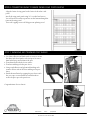
1
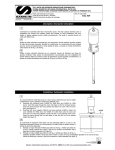
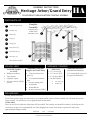
ASSEMBLY INSTRUCTIONS
Heritage Arbor/Grand Entry
HA
PLEASE READ THROUGH BEFORE STARTING ASSEMBLY
COMPONENTS LIST
1
Arbor side panels (2)
2
Headers (2)
3
Braces (4)
Complete
Assembly
Components 5-8
included with
Grand Entry Only
4
2
8
3
4
Caps (7)
5
Wings (2)
6
Post sleeves (2)
7
Post Base Kit (2)
8
Post caps (2)
1
6
5
(Hardware included)
7
YOU WILL NEED
•
•
•
•
HARDWARE PROVIDED
Tools and Supplies
for Arbor
Additional Tools and
Supplies for Grand Entry
•
Phillips screwdriver
Tape measure
Carpenter Square
Pre-mix concrete (120lb)
•
•
(optional)
5’ Pressure treated 4x4
posts (2)
• 2” Galvanized trim head
nails
• Concrete mixing tools
• Wood shims
• Wood adhesive
• Pre-mix concrete (120lb)
Additional Hardware
Arbor only
•
•
2 1/2” screws (8)
3 1/2” screws (22)
9 7/8” spacer block
Anchor stake kit
◊
3/4” screws (8)
◊
Anchors (4)
(Included with Grand Entry)
•
•
2 1/2” washer head screws (8)
#2 square head driver bit
PRELIMINARIES
IF YOU PLAN TO PAINT
If you wish to stain or paint your arbor/entry, we recommend that you do so before assembly, this will make the product
easier to install. Be careful not to cover up guide marks on the rafters.
WORK AREA
Select an area close to where the arbor/entry will be installed. The assembly area should be relatively flat and open with
at least 8’x6’ of space. We recommend the use of the shipping box as your work surface to protect the arbor/entry
against damage during assembly.
445.35.100
1 of 4
9/29/2006
Division of LWO Corp. / P.O. Box 17125 / 3841 North Columbia Boulevard / Portland, Oregon
503-286-5372 / fax 503-286-4092
STEP 1: ATTACHING THE SIDE PANELS TO THE HEADERS
Headers are designed to allow three sizes of opening allowing you to choose
the size of opening that best fits your project needs.
Outside holes for a 60 1/2” opening, center holes are for 54 1/2”, inside holes
are for 48 1/2”. The diagram at right shows a 54 1/2” setting.
Drive the 3 1/2” screw through the top hole in the side panel post, the screw
should stick through about 1/2”. Place the screw point with the appropriate
hole in the header and drive the screw in the rest of the way. Do not drive the
second (lower) screw; these will be installed in Step 2.
Side Panel Post
Header
This hole is to
the inside
Repeat the above process with the second side panel on the other end of the
same header.
STEP 2: SQUARING THE ARBOR
When the arbor is square, drive the second
screws into the posts securing them to the
header.
Install two of the included braces using 2 1/2”
screws.
Turn arbor 180 degrees by lifting the arbor upright and back to the ground so that the second
header is under the posts.
Repeat steps one and two, attaching the header
and braces.
The arbor may be squared by using a carpenter square
between the header and side panel or with the aid of a
measuring tape and careful adjustments.
A=b and x=y.
Brace
STEP 3: INSTALLING THE CAPS
Securely prop the header end of the arbor 7” off the
ground. Use a 3 1/2” screw to install the first cap
into the marked center point on top of the header.
Use the 9 7/8” spacer block and 3 1/2” screws to
install the remaining caps.
445.35.100
Spacer
Block
2 of 4
9/29/2006
Division of LWO Corp. / P.O. Box 17125 / 3841 North Columbia Boulevard / Portland, Oregon
503-286-5372 / fax 503-286-4092
STEP 4: INSTALLING ARBOR IN PROPER LOCATION
The most common method of installation is to secure the arbor to
concrete footings using the four anchors provided. It may also be
possible to secure the arbor to an existing structure, such as a
fence post, if you would like it installed on concrete or decking. If
choosing this option see your local hardware dealer for the applicable hardware.
Diagram 1
Rail
3/4” screws here
Anchor and Concrete Installation
A. Move the arbor to its final location; this will require some
assistance. When you are satisfied with the location mark the
position of the posts, move the arbor aside and lay it carefully
on its side. Dig a hole at least 6” wide and 12” deep for each
post.
B. Attach the anchors to the posts using the 3/4” screws proPost
vided. See Diagram 1.
C. Carefully move the arbor back to its final position, support it
Anchors
plumb and level over the holes with bricks, stones or blocks
of wood under the side panel rails. The post bottoms should
be close to the level of the ground surface. See Diagram 2.
D. Fill each hole with bagged concrete, mixed according to the
manufacture’s instructions. Concrete should come to within
1/4” of the bottom of the post but the post should not be in
concrete.
Anchor butts into
bottom of rail
Side panel
rail
Temporary supports
Post
Concrete
Soil
Diagram 2
STEP 5: SETTING THE POSTS/POST SLEEVES FOR GRAND ENTRY
The following steps only apply if you have purchased the complete Heritage Grand Entry package.
Now that the arbor is in place, measure 33” out from the side
panel post to locate the center position of the 4x4 post.
Align the center of arbor post with the center of the 4x4 post.
Arbor Side
Panel Post
Dig a hole 24” deep and 10” wide; install a 5’ 4x4 pressure treated
post using concrete. The posts should be plumbed in two directions.
Wing
Post
sleeve
Slide the post sleeve over the post with the notched sides facing
the ground. Use shims to elevate the post sleeves 1/4” off the
ground.
Insert wing panel to ensure a good fit, adjust as needed before
concrete has fully set.
Concrete footing
445.35.100
3 of 4
9/29/2006
Division of LWO Corp. / P.O. Box 17125 / 3841 North Columbia Boulevard / Portland, Oregon
503-286-5372 / fax 503-286-4092
4x4 Post
STEP 6: CONNECTING WING TO ARBOR PANELS AND POSTS SLEEVE
Align the lattice of wing-panel to the lattice of the arbor’s side
panel.
Install the wing-panel panel using 2 1/2” washer head screws.
You will need two on the top and two on the bottom through the
frame of the wing-panel.
These self-tapping screws will help prevent splitting wood.
STEP 7: SHIMMING AND TRIMMING POST SLEEVE
• Use shims, adhesive and finish nails or screws to secure
•
•
•
•
the shims and sleeve firmly to the 4x4 post. Be sure to
shim both the top and bottom of the post.
Trim shims flush with the sleeve surface.
Trim base molding to fit the post sleeve.
Using wood adhesive and galvanized finishing nails
connect all four sides of the base molding to the post
sleeve.
Finish the installation by capping the post sleeve with
the post caps, use wood adhesive or finish nails to
secure the post cap to the post sleeve.
Congratulations! You’ve done it!
445.35.100
4 of 4
9/29/2006
Division of LWO Corp. / P.O. Box 17125 / 3841 North Columbia Boulevard / Portland, Oregon
503-286-5372 / fax 503-286-4092