1
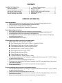
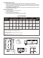
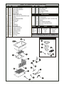
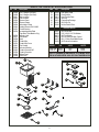
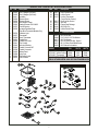
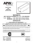
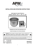
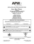
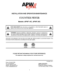
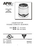
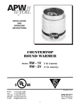
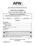
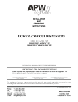
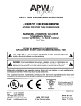
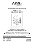
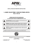
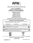
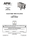
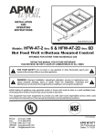
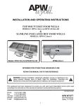
R
INSTALLATION
AND
OPERATING
INSTRUCTIONS
Models:
HFW-1, 1D
HFW-23, -23D
HFW-12, -12D
HOT FOOD WELLS TOP MOUNT, INSULATED
INTENDED FOR OTHER THAN HOUSEHOLD USE
RETAIN THIS MANUAL FOR FUTURE REFERENCE
UNIT MUST BE KEPT CLEAR OF COMBUSTIBLES AT ALL TIMES
!
WARNING: Improper installation, adjustment, alteration, service or maintenance can
cause property damage, injury or death. Read the Installation, Operating and
Maintenance Instructions thoroughly before installing or servicing this equipment.
!
Initial heating of unit may generate smoke or fumes and must be done in a well ventilated area.
Overexposure to smoke or fumes may cause nausea or dizziness.
This equipment has been engineered to provide you with year-round dependable service when used
according to the instructions in this manual and standard commercial kitchen practices.
C
D
SANITATION
SSIFIE
LA
P/N 79967144 6/06
Phone:
Fax:
Toll Free:
Website:
E-mail:
+1 (214) 421-7366
+1 (214) 565-0976
+1 (800) 527-2100
www.apwwyott.com
[email protected]
APW WYOTT
729 Third Avenue
Dallas, TX 75226
1
CONTENTS
OWNER’S INFORMATION.................................2
General Installation.......................................2
General Operating Instructions.....................2
Wet Set-Up (Units w/drains)......................... 2
Dry Set-Up (Units w.o./drains)...................... 2
General Cleaning Instructions...................... 3
General Troubleshooting...............................3
SPECIFICATIONS...............................................3
INSTALLATION................................................... 4
PARTS LISTS w/EXPLODED VIEWS.................5
WIRING DIAGRAMS...........................................8
WARRANTY........................................................11
OWNER’S INFORMATION
General Installation:
1. Always clean equipment thoroughly before first use. (See general cleaning instructions.)
2. Check rating label for your model designation & electrical rating.
3. For best results, use stainless steel countertops.
4. All dimensions in parenthesis in centimeters, unless noted.
General Operating Instructions:
1. All food service equipment should be operated by trained personnel.
2. Do not allow your customers to come in contact with any surface labeled "CAUTION HOT."
3. Where applicable: Never pour cold water into dry heated units.
4. Where applicable, do not cook, warm or hold food directly in liner pans (well pans). Always use
steam table pans/insets, etc.
5. Never hold food below 150°F (66°C)
Wet set-up and operation procedures (units with drains):
1. Add hot water 120°-140°F (50°-60°C) to well pan:
!
!
!
!
!
!
!
!
Four Thirds size units (12x27) use 5-1/2 qts. (1-1/3 gallon) (5.5 litre)
Full size units (12x20) use: 3-3/4 qts. (15 cups) (3.5 litre)
Two Thirds size units use 2-1/2 qts. (10 cups) (2.5 litre)
Half size units use: 1-1/2 qts. (6 cups) (1.5 litre)
One Third size units use: 3 cups (.7 litre)
4 Quart Round use 2 cups (.5 litre)
7 Quart Round use 3 cups (.7 litre)
11 Quart Round use 1-1/4 qts. (5 cups) (1.4 litre)
2. Turn the thermostat control to "10" setting or if equipped with infinite controls to "?" or "Hi". Preheat
for approximately 30 minutes.
3. Place covered inset with preheated product into well.
4. Re-adjust control after another 30 minutes of operation to the "6" setting depending on the amount
and thickness of product.
5. Keep inset/steamtable pan(s) covered to maintain ideal serving temperature.
6. Do not let well run dry.
Dry set-up and operation procedures (units without drains):
1. Turn the thermostat control to "10" setting or if equipped with infinite controls to "7" or "Hi". Preheat
for approximately 30 minutes.
2. Place covered inset with preheated product into well.
3. Re-adjust control after another 30 minutes of operation to the "6" setting depending on the amount
and thickness of product.
4. Keep inset/steamtable pan(s) covered to maintain ideal serving temperature.
2
General Cleaning Instructions:
1. NEVER clean any electrical unit by immersing it in water. Turn off before surface cleaning.
2. Always clean equipment thoroughly before first use. Clean unit daily. Use warm, soapy water
(except where noted on charts). Mild cleansers and PLASTIC scouring pads may be used to
remove baked-on food and water scale.
3. Turn off electrical units before cleaning or servicing. All service should be performed by an APW
Wyott authorized service agency.
General Troubleshooting:
1. Is the unit connected to a live power source?
2. Check circuit breaker.
3. Is power switch on & pilot light glowing?
4. Check rating label. Are you operating unit on proper voltage?
SPECIFICATIONS
Description
(Model #)
Outside Dimensions
L
W
H
Inside Dimensions
L
W
H
FullSize
(HFW-1)
23”
(54.4)
15”
(38.1)
7 3/4”
(19.7)
9 7/8”
(50.5)
2/3 Size
(HFW-23)
16”
(40.6)
15”
(38.1)
7 3/4”
(19.7)
13”
(33)
1/22Size
(HFW-12)
12 ½”
(30.5)
15”
(38.1)
7 3/4”
(19.7)
9 1/2”
(24.1)
11 7/8”
(30.2)
Cut-Out
D
W
Shipping
Weight
6 1/4”
(15.9)
21 3/4”
(55.2)
13 3/4”
(34.9)
25 lbs
(11.4 kg)
11 7/8” 6 1/4”
(30.2) (15.9)
14 5/8”
(37.1)
13 3/4”
(34.9)
22 lbs
(10 kg)
11 7/8”
(30.2)
11 1/2”
(29.2)
13 3/4”
(34.9)
22 lbs
(10 kg)
6 1/4”
(15.9)
NOTE: Top Flange 1 9/16” (3.9cm) all 4 sides, 4 corners 1” (2.5 cm) radius. Standard thermostat has 36”
(91.4 cm) capillary effective length 26” (66 cm).
CONTROL SIZE: 5 5/16” W x 6 7/16” H (13.5 x 13.8)
CONTROL CUTOUT: 5 3/4” W x 6 1/4” H (14.6 x 15.8)
15”
11 7/8”
(30.2)
DRAIN
(OPTIONAL)
0 = 23”
(HFW-1)
16”
(HFW-23)
Outside
12 1/2” (HFW-12)
Length = O
8 1/4”
(15.9 cm)
Inside
Length = I
Recessed Bezel Cut-Out
6 1/4”
(15.9)
7 3/4”
(19.7 cm)
I = 19 7/8” (HFW-1)
13”
(HFW-23)
9 1/2” (HFW-12)
5 3/4”
(14.6)
3
3/8” Dia.
(1.0)
OPTION SPECIFICATIONS
Models
w/Drains
Drain
Location
Drain
Couplings
Full Size
(HFW-1)
HFW-1D
2/3 Size
(HFW-23)
HFW-23D
1 11/16” x 1 11/16”
(4.3 x 4.3) from
back right corner
½ NPT
Stainless
1 1/2” (3.8)
long
1/22Size
(HFW-12)
HFW-12D
Description
Thermostat
72” (182.8)
Capillary
Effective
Length
62” (157.5)
Wood Mt
Kit No’s
Wood Mt
Kit Cut-Out
56431
23 7/8” x 15 7/8”
(60.6 x 40.3)
56460
16 5/8” x 15 7/8”
(42.2 x 40.3)
56413
13 5/8” x 15 7/8”
(34.6 x 40.3)
ELECTRICAL SPECIFICATIONS
Description
Rating at 120VAC, 1PH
Rating at 208VAC, 1PH
Rating at 208/240VAC, 1PH
HFW-1
1500 Watts, 12.5 Amps
1660 Watts, 7.7 Amps
1200/1600 Watts, 5.7/6.7 Amps
HFW-23
800 Watts, 6.7 Amps
HFW-12
800 Watts, 6.7 Amps
500/660 Watts, 2.4/2.8 Amps
INSTALLATION
Installation:
1. Follow applicable General Installation Instructions on page 2.
2. Make applicable Cut-Out per above table. CONNECTION NOTE: Unit is designed for installation in
stainless steel tops. Optional wood mounting kit available.
3. Apply putty tape (Provided) to the underside perimeter of the well rim outer edge.
4. Apply a 1/4" (.6 cm) bead of silicone sealant adjacent to the putty tape on the well flange.
5. Drop well into opening from the top and push down until entire parameter of rim is flush with the
counter surface.
6. From below the counter surface insert an 8" to 10" (20 cm to 25 cm) flat tip screwdriver into the
locking ring tab slots and twist in a clockwise motion to lock well in place.
7. Trim excess putty and sealant from around well rim.
8. Mount control to front panel using hardware. Maintain 4" clearance between well and front panel.
Connect power. Check power. Check nameplate for proper voltage. NOTE: Electrically connect
unit in compliance with local and NEC codes.
4
Item
P/N
1
2
3
4
5
6
56436
55304
56443
56442
56506
56322
55441
56370
56529
56530
56527
56528
56581
55341
55340
55343
55339
56586
56386
56387
56388
7
8
9
10
11
12
13
14
15
16
17
18
19
20
Description
HFW-1, 1D PARTS LIST & EXPLODED VIEW
Pan & Wrapper W/Drain
Pan & Wrapper No Drain
Side Insulation
End Insulation
Reflector Plate
Element 120V-1500W
Element 208/240V-1200/1600W Control
Housing
Increase Decrease Plate
Indicator Light
Thermostat
Knob
Conduit Box
Flex Conduit
Anti Short Bushing
Conduit Connector 90°
Conduit Connector
Conduit Box Cover
Bottom Panel
Bottom Insulation
Hole Cover
Item
P/N
21
22
23
24
56542
56655
55872
56416
Description
Dial Setting Plate
Drain Strainer
Permagum Package
Wire Set
Parts Not Shown
88961
89061
89068
89071
89059
89073
89120
10-24 Green Hex Nut
10-24 Hex Nut
Flat Washer 5/16" X 3/4" X 1/16" #10 Flat
Washer
#10 External Lockwasher
#8 X 1/2" Sheet Metal Screw
Jiffy Clip
MODEL
P/N
VOLTS
WATTS
HFW-1D
HFW-1
HFW-1D
HFW-1
55440
55444
55445
56449
208/240V
208/240V
120V
120V
1200/1600W
1200/1600W
1500W
1500W
FOR 72" THERMOSTAT ADD SUFFIX -72 TO MODEL & P/N
FOR UL KIT ADD SUFFIX -36UL OR -72UL TO MODEL & P/N
UL KIT
22
7
2 1
12
17
13
16
6
5
15
4
8
19
23
9
3
21
10
18
11
20
5
24
14
Item
P/N
Description
1
2
3
4
5
6
7
8
9
10
56409
56459
56411
56412
55990
55695
55696
55960
56370
56529
11
12
13
14
15
16
17
18
19
20
21
56530
56527
56528
56372
56374
55341
55340
55343
55339
56405
56388
HFW-12, 12D PARTS LIST & EXPLODED VIEW
Pan & Wrapper (W/Drain)
Pan & Wrapper (No Drain)
Side Insulation
End Insulation
Element Cover
Element Clamp
Anti-rotation Clamp
Heating Element 120V-800W
Control Housing
Increase-decrease Plate
(Cap-Bulb T-Stat Models Only)
Indicator Light
Thermostat
Knob
Conduit Box
Conduit Box Cover
Flex Conduit
Anti-short Bushing
Conduit Connector 90°
Conduit Connector
Bottom Panel
Hole Cover
Item
P/N
Description
22
23
24
25
26
27
28
56542
56655
50817
56416
55872
89120
55258
Dial Setting Label
Drain Strainer
Heat Transfer Plate
Wire Set
Perma-Gum Package
#105 Jiffy Clip
Infinite Control Plate
Parts Not Shown
89061
89068
89071
88961
89073
89059
MODEL
HFW-12D
HFW-12
#10-24 Hex Nut
5/16 X 3/4 X 1/16 Flat Washer
#10 Flat Washer
#10-24 Green Hex Nut, Ground
#8 X 1/2 Hex Sheet Metal Screw
#10 External Lockwasher
P/N
VOLTS
WATTS
56435
56439
120V
120V
800W
800W
FOR 72" THERMOSTAT ADD SUFFIX -72 TO MODEL & P/N
FOR UL KIT ADD SUFFIX -36UL OR -72UL TO MODEL & P/N
23
UL KIT
2 1
9
14
4
15
16
19
24
28
3
18
10
22
27
8
6
7
26
11
12
5
20
13
25
21
6
17
Item
P/N
1
2
3
4
5
6
7
8
9
56419
56403
56411
55990
55695
55696
55960
56370
56529
10
11
12
13
14
15
16
17
18
19
20
21
22
56530
56527
56528
56581
56586
55341
55340
55343
55339
56426
56388
56542
56655
HFW-23, 23D PARTS LIST & EXPLODED VIEW
Description
Pan & Wrapper (W/Drain)
Pan & Wrapper (No Drain)
Insulation
Element Cover
Element Clamp
Anti-Rotation Clamp
Heating Element 120V-800W
Control Housing
Increase-Decrease Plate
(Cap-Bulb Thermostat Models Only)
Indicator Light
Thermostat
Knob, Thermostat
Conduit Box
Conduit Box Cover
Flex Conduit
Anti-short Bushing
Conduit Connector 90°
Conduit Connector
Bottom Panel
Hole Cover
Dial Setting Label
Drain Strainer
2 1
Item
P/N
Description
23
24
25
50817
55564
69107
26
27
28
29
30
55817
56416
55872
89120
55258
Heat Transfer Plate
Infinite Control
Limiting Thermostat
(Only w/Infinite Control)
Knob, Infinite Control
Wire Set
Perma-Gum Package
#105 Jiffy Clip
Infinite Control Plate
89061
89068
89071
88961
89073
89059
Parts Not Shown
#10-24 Hex Nut
5/16 X 3/4 X 1/16 Flat Washer
#10 Flat Washer
#10-24 Green Hex Nut, Ground
#8 X 1/2 Hex Sheet Metal Screw
#10 External Lockwasher
MODEL
P/N
VOLTS
WATTS
HFW-23 (Thermostat)
56451
120V
800W
HFW-23D (Infinite Control) 56296
120V
800W
HFW-23D (Thermostat)
56450
120V
800W
FOR 72" THERMOSTAT ADD SUFFIX -72 TO MODEL & P/N
FOR UL KIT ADD SUFFIX -36UL OR -72UL TO MODEL & P/N
22
UL KIT
8
13
14
15
18
25
30
23
3
9
17
21
29
7
5
4
6
10
28
11
24
19
12 26
27
20
7
16
WIRING DIAGRAMS
HFW-1, HFW-1D
HEATING
ELEMENT
HEATING
ELEMENT
INDICATOR
LIGHT
ROBERT SHAW
THERMOSTAT
H1
L1
H2
L2
INDICATOR
LIGHT
RANCO
THERMOSTAT
HFW-12, HFW-12D, HFW-23, HFW-23D
THERMOSTAT CONFIGURATION
H1
L1
H2
L2
HFW-23D
INFINITE CONTROL
INDICATOR
LIGHT
HEATING
ELEMENT
HEATING
ELEMENT
P L1 L2
H1
H2
INFINITE
CONTROL
THERMOSTAT
INDICATOR
LIGHT
LIMITING
THERMOSTAT
8
IMPORTANT FOR FUTURE REFERENCE
Please complete this information and retain this manual for the life of the equipment. For
Warranty Service and/or Parts, this information is required.
Model Number
Serial Number
Notes:
9
Date Purchased
Notes:
10
APW WYOTT EQUIPMENT LIMITED WARRANTY
APW Wyott Foodservice Equipment Company warrants it's equipment against defects in materials and workmanship, subject to the
following conditions:
This warranty applies to the original owner only and is not assignable.
Should any product fail to function in its intended manner under normal use within the limits defined in this warranty, at the option of
APW Wyott such product will be repaired or replaced by APW Wyott or its Authorized Service Agency. APW Wyott will only be
responsible for charges incurred or service performed by its Authorized Service Agencies. The use of other than APW Wyott
Authorized Service Agencies will void this warranty and APW Wyott will not be responsible for such work or any charges associated
with same. The closest APW Wyott Authorized Service Agent must be used.
This warranty covers products shipped into the 48 contiguous United States, Hawaii, metropolitan areas of Alaska and Canada. There
will be no labor coverage for equipment located on any island not connected by roadway to the mainland.
Warranty coverage on products used outside the 48 contiguous United States, Hawaii, and metropolitan areas of Alaska and Canada
may vary. Contact the internationalAPW Wyott distributor, dealer, or service agency for details.
Time Period
One year for parts and one year for labor, effective from the date of purchase by the original owner. The Authorized Service Agency
may, at their option, require proof of purchase. Parts replaced under this warranty are warranted for the un-expired portion of the
original product warranty only.
Exceptions
*Gas/Electric Cookline: Models GCB, GCRB, GF, GGM, GGT, CHP-H, EF, EG, EHP. Three (3) Year Warranty on all
component parts, except switches and thermostats. (2 additional years on parts only. No labor on second or third year.)
*Broiler Briquettes, Rock Grates, Cooking Grates, Burner Shields, Fireboxes: 90 Day Material Only. No Labor.
*Heat Strips: Models FD, FDL, FDD, FDDL. Two (2) YearWarranty on element only. No labor second year.
*Glass Windows, Doors, Seals, Rubber Seals, Light Bulbs: 90 Day Material Only. No Labor.
In all cases, parts covered by extended warranty will be shipped FOB the factory after the first year.
Portable Carry In Products
Equipment weighing over 70 pounds or permanently installed will be serviced on-site as per the terms of this warranty. Equipment
weighing 70 pounds or under, and which is not permanently installed, i.e. with cord and plug, is considered portable and is subject to
the following warranty handling limitations. If portable equipment fails to operate in its intended manner on the first day of
connection, or use, at APW Wyott's option or its Authorized Service Agency, it will be serviced on site or replaced.
From day two through the conclusion of this warranty period, portable units must be taken to or sent prepaid to the APW Wyott
Authorized Service Agency for in-warranty repairs. No mileage or travel charges are allowed on portable units after the first day of use.
If the customer wants on-site service, they may receive same by paying the travel and mileage charges. Exceptions to this rule: (1)
countertop warmers and cookers, which are covered under the Enhanced Warranty Program, and (2) toasters or rollergrills which have
in store service.
Exclusions
The following conditions are not covered by warranty:
*Equipment failure relating to improper installation, improper utility connection or supply and problems due to
ventilation.
*Equipment that has not been properly maintained, calibration of controls, adjustments, damage from improper cleaning
and water damage to controls.
*Equipment that has not been used in an appropriate manner, or has been subject to misuse or misapplication, neglect,
abuse, accident, alteration, negligence, damage during transit, delivery or installation, fire, flood, riot or act of god.
*Equipment that has the model number or serial number removed or altered.
If the equipment has been changed, altered, modified or repaired by other than an Authorized Service Agency during or after the
warranty period, then the manufacturer shall not be liable for any damages to any person or to any property, which may result from the
use of the equipment thereafter.
This warranty does not cover services performed at overtime or premium labor rates. Should service be required at times which
normally involve overtime or premium labor rates, the owner shall be charged for the difference between normal service rates and such
premium rates. APW Wyott does not assume any liability for extended delays in replacing or repairing any items beyond its control.
In all cases, the use of other than APW Wyott Authorized OEM Replacement Parts will void this warranty.
This equipment is intended for commercial use only. Warranty is void if equipment is installed in other than commercial application.
Water Quality Requirements
Water supply intended for a unit that has in excess of 3.0 grains of hardness per gallon (GPG) must be treated or softened before
being used. Water containing over 3.0 GPG will decrease the efficiency and reduce the operation life of the unit.
Note: Product failure caused by liming or sediment buildup is not covered under warranty.
“THE FOREGOING WARRANTY IS IN LIEU OF ANY AND ALL OTHER WARRANTIES EXPRESSED OR IMPLIED
INCLUDING ANY IMPLIED WARRANTY OF MERCHANTABILITY OR FITNESS FOR PARTICULAR PURPOSES
AND CONSTITUTES THE ENTIRE LIABILITY OF APW WYOTT. IN NO EVENT DOES THE LIMITED WARRANTY
EXTEND BEYOND THE TERMS STATED HEREIN.”
9/05
11
R
Phone:
Fax:
Toll Free:
Website:
E-mail:
+1 (214) 421-7366
+1 (214) 565-0976
+1 (800) 527-2100
www.apwwyott.com
[email protected]
APW WYOTT
729 Third Avenue
Dallas, TX 75226
12