1
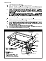
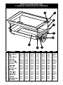
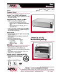
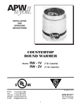
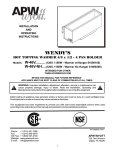
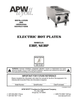
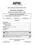
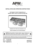
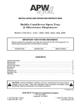
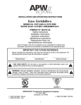
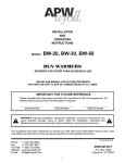
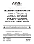
R INSTALLATION AND OPERATING INSTRUCTIONS DROP-IN RACK DISPENSERS Models: DI-1014 DI-1020 DI-1418 DI-1216 DI-1620 DI-1622 DI-2020 RETAIN THIS MANUAL FOR FUTURE REFERENCE IMPORTANT FOR FUTURE REFERENCE Please complete this information and retain this manual for the life of the equipment. For Warranty Service and/or Parts, this information is required. Model Number Serial Number Date Purchased This equipment has been engineered to provide you with year-round dependable service when used according to the instructions in this manual and standard commercial kitchen practices. P/N 88595/88632 9/05 Phone: +1 (307) 634-5801 Fax: +1 (307) 637-8071 APW WYOTT Toll Free: +1 (800) 752-0863 P.O. Box 1829 Website: www.apwwyott.com E-mail: Cheyenne, WY 82003 [email protected] 1 GENERAL INFORMATION Removal of Cables A. B. Turn unit upside down on flat surface. With a box end or hex socket wrench, loosen the two hex head bolts to relax the strap clamps holding the power shaft. The power shaft will turn about one revolution when free of the clamps-keep one hand on the power shaft while loosening the clamps so it will not spin suddenly and cause to "spill" off from the power drums. C. With the aid of another person, unwind the cables from the power drums by pulling the cables up evenly (allowing the power shaft to turn) until the cables are completely off the drums. Do not allow the cables to "spill" off the power drums, as this puts an undesirable twist in the cables. D. With a Phillips head screwdriver, remove screw A and screw B from the power drum and put in a safe place. Do on other side. E. With a box end or hex socket wrench, loosen (do not take apart) the carrier pulleys and tape lock washers on each side. F. With needle nose pliers, pull out the ends of the cable, found in the center of the power drum, about 6" towards you. In back of the two cable ends, find the power drum key. With the needle nose pliers, work the key up and out. Remove the cable through the hole the key came out of. Remove the cable from the carrier pulleys and tape lock washers; discard cable. Re peat on the other side. Installing New Cables A. Center 11 ft. cable between two bottom lock washers. Thread through lock washers and through the guides just above. Bring cable towards the center of the unit, threading between carrier pulley and carrier cable retainer. Tighten hex lock nut on carrier pulley as the retainer is up against the metal flange as far as it can go. Repeat on the other side. B. Position the power shaft with the hole straight up and with the arrow pointing in the direction of the limit cable. Align the hole on the power drum with the hole on the power shaft, showing heads of screws towards you. C. Place ends of the cable in the hole and pull on the ends with a pair of needle nose pliers, bringing the ends out about 6". Do not twist the cables; make sure the right cable is on the right side and the left cable is on the left side. D. Take the power drum key and place in the hole in back of the cables. With a 1/4" punch (screwdriver will do) and a hammer, drive the key down into place making sure it has entered through both holes. E. Pull cables up as far as they will go, and replace screw A in between the right and left cables. Pull the cables in the direction of the arrow and replace screw B over the cables. F. G. Repeat steps B through E on the other side. Hold the cables up, to hold them taut. There will be two loops on each side-use your thumb and index finger to support the loops on each side. H. Have another person wind up the power shaft in the direction of the arrow stamped on the power shaft, until all of the cable is wound back into the power drums. I. Once the cable is wound tight, continue to turn the power shaft an additional 3/4 to one turn (for head load required to support the weight of the mechanism), and tighten the clamp bolt to prevent the tube from turning. J. Align the groove on the tape lock washers with the cable. Tighten down the tape lock washer to prevent slippage of the cable in future use. K. Place the unit back in the counter and depress the platform fully several times to allow the cables to attain their natural position on the power drums. L. If the platform is level, the cable replacement is complete. If the platform is uneven, loosen the four tape lock washers and allow the cables to shift into a balanced tension. To help attain the condition, grip both power drums and apply torque in the direction of rotation that will put additional tension on the cables. Tighten the four tape lockwashers and re-install the unit in the counter. 2 Adjusting the Unit A. B. Turn unit upside down on a flat surface. With a socket or box end wrench, loosen the two hex head bolts to relax the strap clamps holding the power shaft. The power shaft will turn about one revolution when free of the clamps keep one hand on the power shaft while loosening the clamps so it will not spin suddenly and cause the cable to "spill" off from the power drums. C. With the aid of another person, unwind the cables from the power drums by pulling the cables up evenly (allowing the power shaft to turn) until the cables are completely off the drums. Do not allow the cables to "spill" off the power drums, as this puts an undesirable twist in the cables. D. Remove the eight screws from each power drum. If the load rate is to be increased, re-install the screws into a smaller circle of holes. If the load is to be decreased, re-install the screws into the larger circle of holes. Be certain that the same circle of holes is used on both of the power drums. Be certain that the cable emerges between the same relative screw locations on both power drums. E. F. Loosen the cable clamp hex nuts at the four corners under the flange. Hold the cables up to hold them taut. There will be two loops on each side-use your thumb and index finger to support the loops on each side. G. Have another person wind up the torque tube in the direction of the arrow stamped on the power shaft, until all of the cable is wound back into the power drums. H. Once the cable is wound tight, continue to turn the power shaft an additional 3/4 to one turn (for head load required to support the weight of the mechanism), and tighten the clamp bolts to prevent the tube from turning. I. Tighten-the cable clamp hex nuts at the four corners under the flange. J. Place the unit back in the counter and depress the platform fully several times to allow the cables to attain their natural position on the power drums. CABLE REPLACEMENT KIT Tape Lockwasher (Cable Clamp) Flange Weldment Cable Carrier Weldment Carrier Pulley Materials Furnished Power Drum 2 - (Two) Replacement Cables 2 - (Two) Power Drum Keys Tools Needed Needle Nose Pliers Hammer 1/4: Punch (Screwdriver will do) Power Shaft Carrier Pulley Retainer Phillips Head No.3 Screwdriver Box End or Hex Socket Wrenches 3 Shaft Clamp Limit Cable Screw “A” Screw “B” PARTS LIST & EXPLODED VIEW 57 SERIES IN-COUNTER DROP-IN LOWERATOR 9 1 2 3 4 5 8 7 ITEM 6 DESCRIPTION DI-1014 DI-1020 DI-1418 DI-1620 DI-1622 DI-2020 DI-1216 1 Flange Weldment 202152 202151 202150 202149 202148 202147 21103600 2 Cable 30175 30175 30175 30175 30175 30175 30175 3 Carrier Weldment 202137 202136 202135 202133 202134 202132 4 Carrier Pulley 86020 86020 86020 86020 86020 86020 86020 5 Power Drum L.H. 202356 202356 202356 202356 202356 202356 20299700 21103200 Power Drum R.H. 202355 202355 202355 202355 202355 202355 20299700 6 Tube Clamp 202145 202145 202145 202145 202145 202145 202145 7 Cable Retainer 202357 202357 202357 202357 202357 202357 202357 8 Power Shaft 202168 202164 202165 202164 202166 202164 21103900 9 Tape Lock Washer 206535 206535 206535 206535 206535 206535 206535 *10 Limit Cable 30177 30177 30177 30177 30177 30177 30177 *11 Cable Repl. Kit 206853 206853 206853 206853 206853 206853 206853 *12 Power Drum Key 202358 202358 202358 202358 202358 202358 *13 Pulley Bushing 89666 89666 89666 89666 89666 89666 89666 *14 Cable Guide 86028 86028 86028 86028 86028 86028 86028 *15 Limit Cable Bushing 86029 86029 86029 86029 86029 86029 86029 *NOT SHOWN 4 20299500 NOTES: 5 NOTES: 6 APW WYOTT EQUIPMENT LIMITED WARRANTY APW Wyott Foodservice Equipment Company warrants it's equipment against defects in materials and workmanship, subject to the following conditions: This warranty applies to the original owner only and is not assignable. Should any product fail to function in its intended manner under normal use within the limits defined in this warranty, at the option of APW Wyott such product will be repaired or replaced by APW Wyott or its Authorized Service Agency. APW Wyott will only be responsible for charges incurred or service performed by its Authorized Service Agencies. The use of other than APW Wyott Authorized Service Agencies will void this warranty and APW Wyott will not be responsible for such work or any charges associated with same. The closest APW Wyott Authorized Service Agent must be used. This warranty covers products shipped into the 48 contiguous United States, Hawaii, metropolitan areas of Alaska and Canada. There will be no labor coverage for equipment located on any island not connected by roadway to the mainland. Warranty coverage on products used outside the 48 contiguous United States, Hawaii, and metropolitan areas of Alaska and Canada may vary. Contact the international APW Wyott distributor, dealer, or service agency for details. Time Period One year for parts and one year for labor, effective from the date of purchase by the original owner. The Authorized Service Agency may, at their option, require proof of purchase. Parts replaced under this warranty are warranted for the un-expired portion of the original product warranty only. Exceptions *Gas/Electric Cookline: Models GCB, GCRB, GF, GGM, GGT, CHP-H, EF, EG, EHP. Three (3) Year Warranty on all component parts, except switches and thermostats. (2 additional years on parts only. No labor on second or third year.) *Broiler Briquettes, Rock Grates, Cooking Grates, Burner Shields, Fireboxes: *Heat Strips: *Glass Windows, Doors, Seals, Rubber Seals, Light Bulbs: Models FD, FDL, FDD, FDDL. 90 Day Material Only. No Labor. Two (2) Year Warranty on element only. 90 Day Material Only. No labor second year. No Labor. In all cases, parts covered by extended warranty will be shipped FOB the factory after the first year. Portable Carry In Products Equipment weighing over 70 pounds or permanently installed will be serviced on-site as per the terms of this warranty. Equipment weighing 70 pounds or under, and which is not permanently installed, i.e. with cord and plug, is considered portable and is subject to the following warranty handling limitations. If portable equipment fails to operate in its intended manner on the first day of connection, or use, at APW Wyott's option or its Authorized Service Agency, it will be serviced on site or replaced. From day two through the conclusion of this warranty period, portable units must be taken to or sent prepaid to the APW Wyott Authorized Service Agency for in-warranty repairs. No mileage or travel charges are allowed on portable units after the first day of use. If the customer wants on-site service, they may receive same by paying the travel and mileage charges. Exceptions to this rule: (1) countertop warmers and cookers, which are covered under the Enhanced Warranty Program, and (2) toasters or rollergrills which have in store service. Exclusions The following conditions are not covered by warranty: *Equipment failure relating to improper installation, improper utility connection or supply and problems due to ventilation. *Equipment that has not been properly maintained, calibration of controls, adjustments, damage from improper cleaning and water damage to controls. *Equipment that has not been used in an appropriate manner, or has been subject to misuse or misapplication, neglect, abuse, accident, alteration, negligence, damage during transit, delivery or installation, fire, flood, riot or act of god. *Equipment that has the model number or serial number removed or altered. If the equipment has been changed, altered, modified or repaired by other than an Authorized Service Agency during or after the warranty period, then the manufacturer shall not be liable for any damages to any person or to any property, which may result from the use of the equipment thereafter. This warranty does not cover services performed at overtime or premium labor rates. Should service be required at times which normally involve overtime or premium labor rates, the owner shall be charged for the difference between normal service rates and such premium rates. APW Wyott does not assume any liability for extended delays in replacing or repairing any items beyond its control. In all cases, the use of other than APW Wyott Authorized OEM Replacement Parts will void this warranty. This equipment is intended for commercial use only. Warranty is void if equipment is installed in other than commercial application. Water Quality Requirements Water supply intended for a unit that has in excess of 3.0 grains of hardness per gallon (GPG) must be treated or softened before being used. Water containing over 3.0 GPG will decrease the efficiency and reduce the operation life of the unit. Note: Product failure caused by liming or sediment buildup is not covered under warranty. THE FOREGOING WARRANTY IS IN LIEU OF ANY AND ALL OTHER WARRANTIES EXPRESSED OR IMPLIED INCLUDING ANY IMPLIED WARRANTY OF MERCHANTABILITY OR FITNESS FOR PARTICULAR PURPOSES AND CONSTITUTES THE ENTIRE LIABILITY OF APW WYOTT. IN NO EVENT DOES THE LIMITED WARRANTY EXTEND BEYOND THE TERMS STATED HEREIN. 9/05 7 R Phone: +1 (307) 634-5801 Fax: +1 (307) 637-8071 APW WYOTT Toll Free: +1 (800) 752-0863 P.O. Box 1829 Website: www.apwwyott.com E-mail: Cheyenne, WY 82003 [email protected] 8