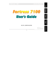
1
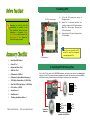
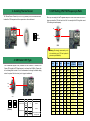
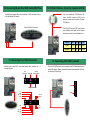
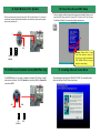
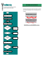
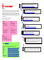
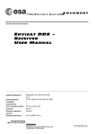
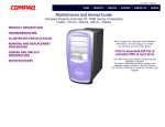
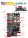
PS/2 Mouse
Connector
SPP/ECP/EPP Print Port
Speaker Out
USB
Connector
RJ45 LAN
Connector
MIC
On-board Sound Connector (DX34)
CD Audio-In (DX34 Only)
PS/2 Keyboard
Connector
COM 2 Port
COM 1 Port
Line In
FAX-VOICE (DX34 Only)
AC97 CODEC Chip
(DX34 Only)
WOL (Wake On LAN)
Connector
Low ESR Capacitor
Intel 82559 10/100
LAN Controller
Dual CPU Sockets
AGP Pro Slot
CPU #1
Thermal Sensor Connector
CPU #2
CPU Fan Connector
32 Bit PCI Slot x 5
VIA Apollo Pro 133A Chipset
4Mbit Flash BIOS
PC-133 DIMM Slot x 3
SCSI HDD LED Connector
SSI ATX Power Connector
Adaptec Ultra3 SCSI Controller
(DX34Plus Only)
AGP Pro Power Connector
System Fan Connector
Redundant SPS Connector
ATA/66 IDE Connector
Dual Channel Ultra3
SCSI Connector
(DX34Plus)
Front Panel Connector
BP (Backplane) Connector
1. Installing CPU
CPU Pin 1 and cut edge
Everything you need to boot this
motherboard is included in this
Easy Installation Guide. For more
information, a complete Online
User's Manual can be found in the
Bonus Pack CD Disc. Thanks for
the help of saving our earth!
1.
Pull up the CPU socket level and up to
90-degree angle.
2.
Locate Pin 1 in the socket and look for a
(golden) cut edge on the CPU upper interface.
Match Pin 1 and cut edge. Then insert the
CPU into the socket.
3.
Press down the CPU socket level and finish
CPU installation.
Note: If you do not match the CPU
socket Pin 1 and CPU cut edge well,
it may damage the CPU.
CPU socket lever
Ø
Hard Drive IDE Cable x 1
Ø
Driver CD x 1
Ø
Norton Anti-Virus CD x1
Ø
ASM Lite CD x 1
Ø
IO Bracket for SV320 x 1
Ø
IO Bracket for Open Market Housing x 1
Ø
SCSI Utility Diskette Pack x 1 (DX34 Plus)
Ø
Ultra 160 SCSI 68 pin Cable x 1 (DX34 Plus)
Ø
CD In Cable x 1 (DX34)
Ø
Screw Pack x 1
Ø
User Manual x 1
Ø
This Easy Installation Guide x 1
PART NO: 90.50F30.002
2. Installing CPU & Housing Fan
Plug in the CPU fan cable to the CPU FAN connector and housing fan cable to the Housing Fan
connector. For DX34 Plus, we provide two configurations of system fan connector for better compatibility
with different housing. Please do take care of the type of connector on your motherboard.
GND
+12V
Sensor
CPU fan
connector
DOC. NO: DX34-EG-E0104C
System fan
connector
+12V
Fan Off (GND)
Fan Fail
Sensor
Two configuration system fan
connector for DX34 Plus
GND
+12V
Sensor
3. Installing Thermal Sensor
5. SW1 Setting CPU FSB Frequency & Ratio
The Thermal Sensor Connector (CN12 & CN1) provides you to use the thermal sensor
to detect the CPU temperature of the components on the motherboard.
When you are using the Intel® engineer sample CPU with DX34/DX34Plus, the SW1
allows you select the CPU ratio from 2x to 9.5 x. You can adjust the SW1 to get the correct
CPU working ratio and frequency.
ON
GND
OFF
1
Sensor
SW1
Warning: We strongly recommend you do
not overclocking your CPU and system for
get more system reliability.
4. SW3 Select CPU Type
This motherboard supports DUAL processors for Intel PentiumII / Pentium!!!, and
Celeron CPU (applied to PPGA package only, must lower than 300MHz). Please refer
to the following table for detail. It is not recommended to change the default setting,
unless the system fails to boot and you’re trying to troubleshoot.
1
OFF
ON
SW3
2
1
ON
2
1
ON
Processor CPU Package
PentiumII
Single Processor Pentium!!!
Celeron
PentiumII
(Default)
Dual Processor
All
Configuration
Default
Frequency
(FSB100)
Frequency
(FSB133)
X2
200
266
On
X2.5
250
333
Off
On
X3
300
400
Off
On
X3.5
350
466
On
On
Off
X4
400
533
On
Off
On
Off
X4.5
450
600
On
On
Off
Off
X5
500
667
On
Off
Off
Off
X5.5
550
733
Off
On
On
On
X6
600
800
Off
Off
On
On
X6.5
650
866
Off
On
Off
On
X7
700
933
Off
Off
Off
On
X7.5
750
1000
Off
On
On
Off
X8
800
1066
Off
Off
On
Off
X8.5
850
1133
Bit1
Bit2
Bit3
Bit4
Ratio
On
On
On
On
On
Off
On
On
On
On
Off
On
All
Default
Off
On
Off
Off
X9
900
1200
Celeron
PPGA
Set the SW3 to OFF
Off
Off
Off
Off
X9.5
950
1266
Celeron
FC-PGA
Not Supported
Pentium!!!
6. Install DIMM Modules
8. Connecting Redundant SPS Connector
This motherboard has three 168-pin DIMM sockets that allow you to install PC100 or
PC133 memory up to 1.5GB. This motherboard supports not only SDRAM but also VCM
and Registered DRAM.
This motherboard implements Redundant SPS connector to provide better expansibility
on superior server. It is feasible to install an additional 337-watts power supply module
(optional) in a hot-swappable redundant configuration, which enables a fully-configure
system to continue running even if one power module fails.
Tip: The driving capability of new generation
chipset is limited due to the lack of a memory
buffer (to improve performance). This makes
DRAM chip count an important factor to take
into consideration when you install DIMMs.
Unfortunately, there is no way that the BIOS
can identify the correct chip count, you need
to calculate the chip count by yourself.
Present 1
2
I C CLK
Fan 1 Fail
PS 1 Fail
PS_ON
PS 3 Fail
Fan 3 Fail
13
1
14
2
2
I CDA
Present 3
GND
PS 2 Fail
Fan 2 Fail
Present 2
5VSB
DIMM 3
DIMM 2
DIMM 1
7. Connecting ATX and AGP Pro Power Connector
9. Connecting IDE & FDD Cable
The DX34 / DX34Plus uses Intel® SSI (Server System Infrastructure) type 24-pin ATX
power connector. The 6-pin AGP Pro Power connector provides extra +5V and +3.3V
power for AGP Pro VGA card. Make sure you plug in the right direction.
Connect 34-pin floppy cable and 40-pin ATA66 or ATA33 IDE cable to floppy connector
FDC and IDE connector IDE1, IDE2. Pin1 of cable is normally marked with red color. Be
careful of the pin1 orientation. Wrong orientation may cause system damage.
24-pin ATX Power connector
Primary
Master (1st)
Primary
Slave (2nd)
FDD
Connector
IDE1 (Primary)
13
+12V
5VSB
1
+5V
+5V
-5v
PWR OK
AGP Pro Power
Connector
6
+5V
+3.3V
+3.3V
1
GND
GND
GND
COM
+5V
COM
COM
COM
+5V
COM
PS-ON
COM
+3.3V
COM
-12V
+3.3V
+3.3V
20
19
ATA/66 IDE
Connector
IDE2 (Secondary)
Pin 1
Secondary
Master (3rd)
Secondary
Slave (4th)
10. Connecting 68-pin Ultra3 SCSI Cable (DX34 Plus)
The DX34Plus provides two 68-pin Ultra Wide/Ultra 2/3 SCSI connectors for 16-bit
or 16-bit differential SCSI devices.
68-pin SCSI Ultra3 Connectors
12. CD-IN & FAX-Voice Connector (Applied to DX34)
If you have installed the CD-ROM drive in the
system, the CD-In Connector (CN19) can be
connected to audio output connector of internal
CD-ROM drive.
This FAX-VOICE connector (CN21) can let the fax
sound of Modem device speak out from external
speaker by connected .to internal Modem card.
Connector
Pin1
Pin2
Pin3
Pin4
CD-IN
Left
GND
GND
Right
MIC-IN GND
GND
Phone
FAX-Voice
11. Connecting Front Panel Connector
13. Connecting SCSI LED Connector
Attaching such as power LED, reset switch, power switch connector, etc.…
corresponding pins.
ATX
Power Switch
Power LED
to
Chassis
Intrusion Switch
1
21
2
22
The 4-pin SCSI LED connector can be connected to the SCSI hard disk control card
activity LED connector. Read or write activity by devices connected to the SCSI card
will cause the LED lighting up.
+
CN23
+
-
HDD LED Reset Switch
+5V
GND
PWR LED
+5VSB
GND
+5V
HDD LED
HDD LED
+5V
CN24
RST S/W
INT S/W
1
21
2
22
GND
GND
+
+
-
16. Power-On and Load BIOS Setup
14. Select Buzzer or Ext. Speaker
There is one jumper cap over pin1 and pin2 of JP4 for internal buzzer. If you want to
use external case-mounted speaker instead of internal buzzer, please remove jumper
cap to short pin2 and pin3.
After you finish the setting of jumpers and connect correct cables. Power on and
enter the BIOS Setup, press <Del> during POST (Power On Self Test). Choose
"Load Default Setting" for recommended optimal performance.
Del
1
1
JP4
1
Buzzer
Warning: Please avoid of using
"Load Turbo Defaults", unless you
are sure your system components
(CPU, DRAM, HDD, etc.) are good
enough for turbo setting.
Speaker
(Default)
15. SCSI Channel Terminator Control (DX34 Plus only)
The JP3/JP3X allows you to enable or disable the on-board SCSI Channel A and B
terminator control function. The SCSI Channel A is controlled by JP3; the Channel B is
controlled by JP3X.
JP3
JP3X
1
1
ON
(Default)
OFF
17. Installing Onboard Sound Driver
This motherboard comes with an AD 1885 AC97 CODEC. You can find the audio
driver from the Bonus Pack CD disc autorun menu.
Part Number and Serial Number
If you encounter any trouble to boot you system, follow the
procedures accordingly to resolve the problem.
The Part Number and Serial number are printe d on bar code label. You can find this
bar code label on the outside packing, on ISA/CPU slot or on component side of PCB.
For example:
Start
Turn off the power and unplug the AC power cable, then remove all
of the addon cards and cables, including VGA, IDE, FDD, COM1,
COM2 and Printer.
Part No.
Make sure if the jumper settings for CPU and DRAMs are correct.
Serial No.
Clear CMOS.
Part No.
Install the VGA card. Then connect your monitor and keyboard.
Serial No.
P/N: 91.88110.201 is part number, S/N: 91949378KN73 is serial number.
Turn on the power, and check if
the power supply and CPU fan
work properly.
No
The problem was probably caused
by power supply or motherboard
failure. Please contact your reseller
or local distributor for repairing.
Yes
No
Check if there is display.
Perhaps your VGA card or monitor
is defective.
Yes
Press Ctrl, and Alt key at the
same time, hold them and then
press Del to see if the
system reboots.
No
It is very possible that your keyboard
is defective.
Yes
During system rebooting, press Del to enter BIOS Setup. Choose
“Load Setup Default".
Turn off the system and
re- connect the IDE cable.
Check if the system can
reboot successfully.
Yes
Re- install Windows 95, Windows 98 or Windows NT.
End
No
The problem should be caused by the
IDE cables or HDD itself.
1
Online Manual: Please check the manual carefully and make sure the
jumper settings and installation procedure are correct.
http://www.aopen.com/tech/download/manual/default.htm
Dear Customer,
2
Thanks for choosing AOpen products. To provide the best and fastest service to
our customer is our first priority. However, we receive numerous emails and
phone-calls worldwide everyday, it is very hard for us to serve everyone on time.
We recommend you follow the procedures below and seek help before contact
us. With your help, we can then continue to provide the best quality service to
more customers.
Thanks very much for your understanding!
AOpen Technical Supporting Team
Pacific Rim
AOpen Inc.
Tel: 886-2-2696-1333
Fax: 886-2-8691-2233
Europe
AOpen Computer b.v.
Tel: 31-73-645-9516
Fax: 31-73-645-9604
China
Germany
AOpen Computer GmbH.
Tel: 49-2102-157700
Fax: 49-2102-157799
( )
Tel: 49-2102-157700
Fax: 49-2102-157799
3
Test Report: We recommend to choose board/card/device from the
compatibility test reports for assembling your PC.
http://www.aopen.com/tech/report/default.htm
FAQ: The latest FAQ (Frequently Asked Questions) may contain a
solution to your problem.
http://www.aopen.com/tech/faq/default.htm
Download Software: Check out this table to get the latest updated
BIOS/utility and drivers.
http://www.aopen.com/tech/download/default.htm
4
5
News Group: Your problem probably had been answered by our support
engineer or professional users on the news group.
http://www.aopen.com/tech/newsgrp/default.htm
America
AOpen America Inc.
Tel: 1-510-498-8928
Fax: 1-408-922-2935, 1-408-432-0496
6
Contact Distributors/Resellers: We sell our products through resellers
and integrators. They should know your system configuration very well and
should be able to solve your problem more efficien n important reference for
you if next time you want to buy something else from them.
Web Site: www.aopen.com
E-mail: Send us email by going through the contact form below.
English
http://www.aopen.com.tw/tech/contact/techusa.htm
Japanese
http://www.aopen.co.jp/tech/contact/techjp.htm
Chinese
http://www.aopen.com.tw/tech/contact/techtw.htm
German
http://www.aopencom.de/tech/contact/techde.htm
French
http://france.aopen.com.tw/tech/contact/techfr.htm
Simplified Chinese
http://www.aopen.com.cn/tech/contact/techcn.htm
7
Contact Us: Please prepare detail system configuration and error symptom
before contacting us. The part number, serial number and BIOS version
are also very helpful.