1
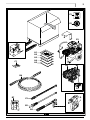
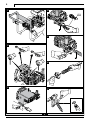
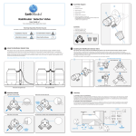
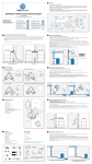
РУССКИЙ
ESPAÑOL
ITALIANO
DEUTSCH
ENGLISH
cod. 90665 - FZ
FRANÇAIS
850
FR Lire ce manuel avant l’installation/utilisation du nettoyeur en faisant très attention aux INSTRUCTIONS POUR LA SÉCURITÉ
EN Read this manual through carefully before installing/using the cleaner, paying special attention to the SAFETY
INSTRUCTIONS
DE Lesen Sie dieses Handbuch vor der Installation und dem Gebrauch des Hochdruckreinigers aufmerksam durch und achten
Sie besonders auf die SICHERHEITSANWEISUNGEN
IT
Leggere questo manuale prima dell’installazione/uso dell’idropulitrice, prestando particolare attenzione alle ISTRUZIONI
PER LA SICUREZZA
ES Leer este manual antes de la instalación/uso de la hidrolimpiadora, prestando particular atención a las INSTRUCCIONES
SOBRE SEGURIDAD
RU Прочитайте данное руководство перед установкой моечной машины, обращая особенное внимание на
ИНСТРУКЦИИ ПО БЕЗОПАСНОСТИ
DÉCLARATION DE CONFORMITÉ
FR
DECLARATION OF CONFORMITY
EN
DE
KONFORMITÄTSERKLÄRUNG
Nous déclarons, en assumant la pleine responsabilité
de cette déclaration, que le produit est conforme aux
normes suivantes et aux documents correspondants
We declare under our sole responsibility that this
product is in conformity with the following
standards or standardized documents
Wir erklären in alleiniger Verantwortung,
dass das Produkt den folgenden Normen
und normativen Dokumenten entspricht:
EN 60335-2-79:2004
Selon les prescriptions des directives :
EN 60335-2-79:2004
In accordance with the regulations:
EN 60335-2-79:2004
gemäß den Bestimmungen der Richtlinien:
98/37/CE
73/23/CEE, 89/336/CEE, 2000/14/CE
98/37/EC
EEC 73/23, EEC 89/336, 2000/14/EC
98/37/EG
73/23/EWG, 89/336/EWG, 2000/14/EG
Date : 24/03/2006
MODENA (I)
Stefano Reverberi
Managing Director
DICHIARAZIONE DI CONFORMITÀ
Date: 24/03/2006
MODENA (I)
Stefano Reverberi
Managing Director
IT
DECLARACIÓN DE CONFORMIDAD
Datum: 24.03.2006
MODENA (I)
Stefano Reverberi
Managing Director
ES
ДЕКЛАРАЦИЯ СООТВЕТСТВИЯ
RU
Dichiariamo, assumendo la piena responsabilità
di tale dichiarazione, che il prodotto è conforme
alle seguenti normative e ai relativi documenti
Declaramos, asumiéndonos la plena responsabilidad al
respecto, que el producto cumple con lo establecido por
las siguientes normativas y relativos documentos:
Заявляем, возлагая на себя полную ответственность за
данную декларацию, что данная продукция соответствует
следующим нормам и соответствующим документам
EN 60335-2-79:2004
in base alle prescrizioni delle direttive:
EN 60335-2-79:2004
sobre la base de lo dispuesto por las directivas:
EN 60335-2-79:2004
на основании требований директив:
98/37/CE
CEE 73/23, CEE 89/336, 2000/14/CE
98/37/CE
73/23/CEE, 89/336/CEE y 2000/14/CE
98/37/EC
73/23/EEC, 89/336/EEC, 2004/14/EC
Data: 24/03/2006
MODENA (I)
Stefano Reverberi
Managing Director
Fecha: 24/03/2006
MÓDENA (I)
Stefano Reverberi
Managing Director
Дата: 24/03/2006
Модена (Италия)
Стефано Ревербери
Управляющий директор
E1
E2
B1
A1
A2
A3
A4
A5
C1
B3
B2
B6
D1
B7
D
C2
B5
B4
1
1
4
Ø13
5
2
6
3
7
2
1
2
G
E
3
1
3
2
D
1
I
2
4
1
2
3
L
1
2
5
10
English
1 GENERAL INFORMATION (FIG. 1)
2.3 Improper use
Use by unskilled persons or those who have not read
and understood the instructions in the manual is forbidden.
The introduction of inflammable, explosive and toxic
liquids into the cleaner is prohibited.
Use of the cleaner in a potentially inflammable or explosive atmosphere is forbidden.
The use of non-original accessories and any other
accessories not specifically intended for the model in
question is prohibited.
All modifications to the cleaner are prohibited. Any
modifications made to the appliance shall render the
Declaration of Conformity null and void and relieve the
manufacturer of all liability under civil and criminal law.
1.1 Use of the manual
The USE • MAINTENANCE manual forms an integral part
of the power-jet cleaner and should be kept for future
reference.
Please read it carefully before installing/using the appliance.
Read the engine manufacturer’s manual carefully.
If the appliance is sold, the seller must pass on the
manuals to the new owner along with the appliance.
1.2 Delivery
The cleaner is delivered partially assembled in a cardboard box, fixed to a pallet.
Caution - Danger!
Suitable lifting equipment must be used when
lifting the power-jet cleaner.
The supply package is illustrated in fig.1
1.2.1 Documentation supplied with the appliance
A1
A2
A3
A4
A5
Use and maintenance manual
Safety instructions
Declaration of conformity
Technical data
Engine instruction manual
1.3 Disposing of packaging
The packaging material must be disposed of in accordance with the relevant legal requirements.
1.4 Safety signs
Comply with the instructions provided by the safety
signs fitted to the cleaner.
Check that they are present and legible; otherwise, fit
replacements in the original positions.
E1 sign - indicates that the cleaner must not be disposed of as municipal waste; it may be handed in to the
dealer on purchase of a new cleaner.
The cleaner’s electrical and electronic parts must not be
reused for improper uses since they contain substances
which constitute health hazards.
E2 sign - indicates that ear defenders must be worn.
2 TECHNICAL INFORMATION (fig. 1)
2.1 Envisaged use
This appliance has been designed for individual and
professional use for the cleaning of vehicles, machines,
boats, masonry, etc, to remove stubborn dirt using clean
water and biodegradable chemical detergents.
Vehicle engines may be washed only if the dirty water is
disposed of as per regulations in force.
- Intake water temperature: below 60 °C.
- Intake water pressure: below 10 bar.
- Operating ambient temperature: above 0 °C.
The power-jet cleaner is compliant with the 98/37/EC
Directive.
2.2 Operator
Use of the cleaner requires specific technical skill and
training and a good sense of responsibility.
The operator must meet specific physical and mental
requirements to be suitable for the job in hand; the cleaner must therefore only be used by the appointed person.
2.4 Main components
B1
B2
B3
B4
B5
B6
B7
- Engine
- Reduction gearbox (where fitted)
- Pump
- Gun with safety catch
- Lance
- High pressure hose
- Oil caps
2.4.1 Accessories
C1 Nozzle cleaning tool
C2 Rotopower (where fitted)
2.5 Technical data
The technical data are specified in the enclosure.
2.6 Safety devices
Caution - Danger!
Never tamper with the safety devices.
- Safety valve and pressure limiting valve
The safety valve is also a pressure limiting valve. When
the gun trigger is released, the valve opens and the
water recirculates through the pump inlet.
- Thermostat valve (D1)
If the water temperature exceeds the temperature set
by the manufacturer, the thermostat valve discharges
the hot water and draws in an amount of cold water
equal to the amount of water discharged.
- Safety catch (D): prevents accidental spraying of water.
2.7 Noise levels
At even short exposure times, noise may cause hearing
impairment in the long term.
Users must wear ear defenders to protect their
hearing.
3 INSTALLATION (fig. 2)
3.1. Assembly
Caution - Danger!
All installation and assembly operations must
be performed with the engine off.
The assembly sequence is illustrated in fig. 2.
3.2 Fitting the pressure release caps
To prevent oil leaks, the appliance is delivered with the
oil intakes sealed with red caps which must be replaced
with the pressure release caps supplied.
English
3.3 Assembling the rotating nozzle (where fitted)
3) Keep the gun trigger depressed and start the
engine.
4) Keep the gun trigger depressed for a few seconds to
vent the air from the pump.
To prevent damage to the appliance, when running
do not stop the water jet for more than 5 minutes
at a time.
The rotating nozzle kit delivers greater washing power.
3.4 Water supply connection
Caution - Danger!
3.4.1 Connection points
l Water outlet (OUTLET)
n Water inlet with filter (INLET)
3.4.2 Connection to the mains water supply
The cleaner can be connected directly to the
mains drinking water supply only if the supply
hose is fitted with a backflow preventer valve
as per current regulations in force. Make sure
that the hose is at least Ø 13 mm and that it is
reinforced.
5.4 Stopping
1) Stop the engine.
2) Depress the gun trigger and discharge the residual
pressure inside the hoses.
3) Engage the gun safety catch (D).
5.5 Refilling and using detergent
IPlace the hose straight in the detergent container.
5.6 Recommended cleaning procedure
Dissolve dirt by applying the detergent mixed with
water to the surface while still dry.
When dealing with vertical surfaces work from the bottom upwards.
Leave the detergent to act for 1-2 minutes but do not
allow the surface to dry. Starting from the bottom, use
the high pressure jet at a minimum distance of 30 cm.
Do not allow the rinse water to run onto unwashed
surfaces.
4 ADJUSTMENTS (fig. 3)
4.1 Adjusting the pressure
The regulator (G) is used to adjust the working pressure.
The pressure is shown on the pressure gauge.
5.7 Ending the working session
1) Stop the engine.
2) Turn off the water supply tap.
3) Discharge the residual pressure from the gun until all
the water has come out of the nozzle.
4) Engage the gun safety catch (D).
5) Remove the water intake hose.
6) Remove the detergent hose from the container.
4.2 Adjusting the nozzle
Water flow is adjusted by regulating the nozzle (E).
5 INFORMATION FOR USE (fig. 4)
Caution - Danger!
Never use the cleaner when malfunctioning.
In the event of damage, the high pressure hose must
be replaced immediately to prevent bursts.
6 MAINTENANCE (fig. 5)
5.1 Preliminary checks
Before using the cleaner, check the oil level:
- in the engine (see engine constructor’s manual);
- in the reduction gearbox (where fitted);
- in the pump.
Check the reduction gearbox and pump oil gauges to
check the oil level. It should be halfway up the gauge. If
necessary, top up with oil having the same characteristics (see the “Oil characteristics” table).
5.2 Controls
For information about the engine controls, refer to the
engine constructor’s manual.
- Water jet control lever (I).
Any maintenance operations not covered by this chapter should be carried out by an Authorised Sales and
Service Centre.
Caution - Danger!
Stop the engine before doing any work on
the cleaner.
6.1 Cleaning the filter
Clean the suction filter (L) after every 50 hours of operation.
6.2 Topping up the oil level
The oil level must be topped up with the cleaner on a
flat surface.
Remove the casing (where fitted) to top up the oil level.
Replace the casing (where fitted) when done.
Caution - Danger!
During operation the cleaner must be positioned on a flat surface firm enough to support it
securely.
5.3 Starting the appliance
Caution - Danger!
Before starting up the cleaner check that the
water supply hose is connected properly; use of the
cleaner without water will damage the appliance.
1) Turn the water supply tap fully on.
2) Release the safety catch (D).
6.2.1 Topping up the pump oil
Add oil through the intake hole to restore the
correct level.
For oil characteristics, refer to the “Oil characteristics” table.
6.2.2 Topping up the reduction gearbox oil (where fitted)
Add oil through the intake hole to restore the
correct level.
For oil characteristics, refer to the “Oil characteristics” table.
ENGLISH
Only clean or filtered water should be used for
intake. The delivery of the water intake tap should
be equal to that of pump capacity.
Do not use container and tanks to supply the appliance.
Place the cleaner as close to the water supply system
as possible.
11
12
English
6.3 Oil Change
Table 1 - Oil characteristics
Caution - Danger!
Component
Spent oil must not be dumped because it is a
pollutant. It must be disposed of in accordance with
legal requirements.
Change pump and reduction gearbox oil (where fitted)
after first 50 hours of operation, and every 500 hours
thereafter.
Remove the casing (where fitted) to change the oil.
Replace the casing (where fitted) when done.
6.3.1 Changing the pump oil
Unscrew the drain plug and allow all the spent oil
to flow out.
Screw the plug back into place.
Pour in oil through the filler hole.
Check that the oil level is correct.
For oil characteristics, refer to the “Oil characteristics” table.
Oil type
Quantity (kg)
Pump 850
SAE 30 W
0.9
Pump 840
SAE 30 W
0.9
Pump 830
SAE 30 W
0.3
Pump 820
SAE 30 W
0.3
Pump 810
SAE 75 W90
0.135
Reduction
gearbox
AGIP BLASIA W90
0.21
6.4 Storage
Treat the appliance with non-corrosive, non-toxic antifreeze before storing it away for winter.
6.3.2 Changing the reduction gearbox oil (where fitted)
7
Unscrew the drain plug and allow all the spent
oil to flow out.
Screw the plug back into place.
Pour in oil through the filler hole.
Check that the oil level is correct.
For oil characteristics, refer to the “Oil characteristics” table.
TROUBLESHOOTING
Problem
Possible causes
Nozzle worn
Water filter fouled
Water supply pressure low
Pump does not reach work- Air being sucked into system
ing pressure
Air in pump
Pressure drops during use
Adjustable nozzle not positioned correctly
Water intake from external tank
Intake water too hot
Nozzle clogged
Water leakage
Seals worn
Cleaner noisy
Oil leakage
Engine malfunction
Water escapes from thermostat valve
Water too hot
Seals worn
Water temperature inside nozzle has exceeded
max. rated value stated on nameplate
Remedy
Replace nozzle
Clean filter (fig.5)
Turn on water supply tap fully
Check tightness of hose fittings
Switch off the cleaner and keep depressing and
releasing the gun trigger until the water comes out
in a steady flow. Switch the cleaner back on again.
Turn the adjustable nozzle “E” (+) (fig.3)
Connect cleaner to the mains water supply
Reduce temperature
Clean nozzle (fig.5)
Have the seals replaced at your nearest Authorised
Service Centre
Reduce temperature (see technical data
Contact your nearest Authorised Service Centre
Refer to the engine manufacturer’s manual.
With appliance in operation, do not stop the water
jet for more than 5 minutes at a time