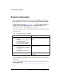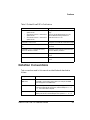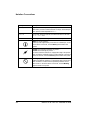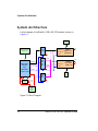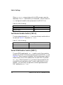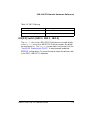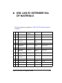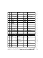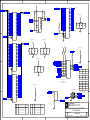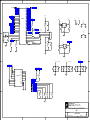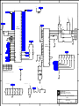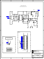
1
Blackfin® USB-LAN EZ-Extender®
Manual
Revision 2.1, March 2008
Part Number
82-000845-01
Analog Devices, Inc.
One Technology Way
Norwood, Mass. 02062-9106
a
Copyright Information
©2008 Analog Devices, Inc., ALL RIGHTS RESERVED. This document
may not be reproduced in any form without prior, express written consent
from Analog Devices, Inc.
Printed in the USA.
Limited Warranty
The USB-LAN EZ-Extender is warranted against defects in materials and
workmanship for a period of one year from the date of purchase from
Analog Devices or from an authorized dealer.
Disclaimer
Analog Devices, Inc. reserves the right to change this product without
prior notice. Information furnished by Analog Devices is believed to be
accurate and reliable. However, no responsibility is assumed by Analog
Devices for its use; nor for any infringement of patents or other rights of
third parties which may result from its use. No license is granted by implication or otherwise under the patent rights of Analog Devices, Inc.
Trademark and Service Mark Notice
The Analog Devices icon bar and logo, Blackfin, VisualDSP++, EZ-KIT
Lite, and EZ-Extender are registered trademarks of Analog Devices, Inc.
All other brand and product names are trademarks or service marks of
their respective owners.
Regulatory Compliance
The USB-LAN EZ-Extender is designed to be used solely in a laboratory
environment. The board is not intended for use as a consumer end product or as a portion of a consumer end product. The board is an open
system design which does not include a shielded enclosure and therefore
may cause interference to other electrical devices in close proximity. This
board should not be used in or near any medical equipment or RF devices.
The USB-LAN EZ-Extender has been certified to comply with the essential requirements of the European EMC directive 89/336/EEC amended
by 93/68/EEC and therefore carries the “CE” mark.
The USB-LAN EZ-Extender has been appended to Analog Devices, Inc.
Technical Construction File (TCF) referenced ‘DSPTOOLS1’ dated
December 21, 1997 and was awarded CE Certification by an appointed
European Competent Body as listed below.
Technical Certificate No: Z600ANA1.022
Issued by: Technology International (Europe) Limited
60 Shrivenham Hundred Business Park
Shrivenham, Swindon, SN6 8TY, UK
The EZ-KIT Lite evaluation system contains ESD (electrostatic discharge)
sensitive devices. Electrostatic charges readily accumulate on the human
body and equipment and can discharge without detection. Permanent
damage may occur on devices subjected to high-energy discharges. Proper
ESD precautions are recommended to avoid performance degradation or
loss of functionality. Store unused EZ-KIT Lite boards in the protective
shipping package.
CONTENTS
PREFACE
Product Overview ......................................................................... viii
Purpose of This Manual .................................................................. ix
Intended Audience .......................................................................... ix
Manual Contents ............................................................................. x
What’s New in This Manual ............................................................. x
Technical or Customer Support ....................................................... xi
Supported Products ......................................................................... xi
Product Information ...................................................................... xii
Notation Conventions ................................................................... xiii
USB-LAN EZ-EXTENDER INTERFACES
USB-LAN EZ-Extender Setup ....................................................... 1-1
USB Software ......................................................................... 1-2
Ethernet Software .................................................................... 1-3
USB 2.0 Interface ......................................................................... 1-3
Ethernet Interface ......................................................................... 1-4
Optional ADSP-BF537 EZ-KIT Lite Interfaces ............................. 1-5
Power-Over-Ethernet ............................................................... 1-5
Blackfin USB-LAN EZ-Extender Manual
v
CONTENTS
MII Interface .......................................................................... 1-6
USB-LAN EZ-EXTENDER HARDWARE REFERENCE
System Architecture ...................................................................... 2-2
Jumper Settings ............................................................................ 2-3
Power Select Jumper (JP1) ....................................................... 2-4
LAN Power Jumper (JP2) ........................................................ 2-5
Link Jumper (JP3) .................................................................. 2-5
Switch Settings ............................................................................. 2-6
ADDR Enable Switch (SW1.1) ............................................... 2-6
FLAGS Enable Switch (SW1.2) ............................................... 2-7
USB IRQ Enable Switch (SW1.3) ........................................... 2-7
Test Mode Enable Switch (SW1.4) .......................................... 2-8
Serial ROM Enable Switch (SW2.1) ........................................ 2-8
IOS[2:0] Switch (SW2.2, SW2.3, SW2.4) ............................... 2-9
USB-LAN EZ-EXTENDER BILL OF MATERIALS
USB-LAN EZ-EXTENDER SCHEMATIC
Title Page ..................................................................................... B-1
Expansion Interface ...................................................................... B-2
Bus Switches ................................................................................. B-3
USB ............................................................................................. B-4
LAN ............................................................................................ B-5
PoV, MII, and Power Selection ...................................................... B-6
INDEX
vi
Blackfin USB-LAN EZ-Extender Manual
PREFACE
Thank you for purchasing the Blackfin® USB-LAN EZ-Extender®, Analog Devices, Inc. extension board to the EZ-KIT Lite® evaluation system
for ADSP-BF533, ADSP-BF537, and ADSP-BF561 Blackfin processors.
The Blackfin processors are embedded processors that support a Media
Instruction Set Computing (MISC) architecture. This architecture is the
natural merging of RISC, media functions, and digital signal processing
characteristics towards delivering signal processing performance in a
microprocessor-like environment.
The EZ-KIT Lite and USB-LAN EZ-Extender are designed to be used in
conjunction with the VisualDSP++® development environment. VisualDSP++ offers a powerful programming tool with new flexibility that
significantly decreases the time required to port software code to a processor, reducing time-to-market.
To learn more about Analog Devices development software, go to
http://www.analog.com/processors/tools/.
Blackfin USB-LAN EZ-Extender Manual
vii
Product Overview
Product Overview
The Blackfin USB-LAN EZ-Extender is a separately sold extension board
that plugs onto the expansion interface of the ADSP-BF533,
ADSP-BF537, or ADSP-BF561 EZ-KIT Lite evaluation system. The
extension board aids the design and prototyping phases of the
ADSP-BF533, ADSP-BF537, or ADSP-BF561 processor targeted
applications.
The board extends the capabilities of the evaluation system by providing a
connection between the asynchronous memory bus of the Blackfin processor (asynchronous memory bank 3) and either a USB 2.0 or a 10/100
Mbps Ethernet device.
The following is a list of the Blackfin USB-LAN EZ-Extender interfaces.
• USB 2.0 interface
D
D
D
PLX’s Technology Netchip 2272 device
USB driver and application code
USB logo certified
• Ethernet interface
D
D
D
D
SMSC’s LAN 91C111 device supported on the
ADSP-BF533 EZ-KIT and ADSP-BF561 EZ-KIT Lites
IEEE802.3.AF compliant Power-Over-Ethernet (PoE)
application on the ADSP-BF537 EZ-KIT Lite
SMSC’s MII connector to evaluate different PHYs with the
ADSP-BF537 EZ-KIT Lite
Ethernet stack and application code
• No power supply required
D
Derives power from EZ-KIT Lite
• CE certified
viii
Blackfin USB-LAN EZ-Extender Manual
Preface
• Dimensions
D
3.13 in (H) x 3.6 in (W)
Before using any of the interfaces, follow the setup procedure in
“USB-LAN EZ-Extender Setup” on page 1-1.
Example programs are available to demonstrate the capabilities of the
Blackfin USB-LAN EZ-Extender board.
Purpose of This Manual
The Blackfin USB-LAN EZ-Extender Manual describes operation and configuration of the extension board components. A schematic and a bill of
materials are provided as a reference for future Blackfin processor board
designs.
Intended Audience
This manual is a user’s guide and reference to the Blackfin USB-LAN
EZ-Extender. Programmers who are familiar with the Analog Devices
Blackfin processor architecture, operation, and development tools are the
primary audience for this manual.
Programmers who are unfamiliar with VisualDSP++ or EZ-KIT Lite evaluation software should refer to the ADSP-BF533, ADSP-BF537, or
ADSP-BF561 Evaluation System Manual, VisualDSP++ online Help, and
user’s or getting started guides. For the locations of these documents, refer
to “Product Information”.
Blackfin USB-LAN EZ-Extender Manual
ix
Manual Contents
Manual Contents
The manual consists of:
• Chapter 1, “USB-LAN EZ-Extender Interfaces” on page 1-1
Provides basic board information.
• Chapter 2, “USB-LAN EZ-Extender Hardware Reference” on
page 2-1
Provides information on the hardware aspects of the board.
• Appendix A, “USB-LAN EZ-Extender Bill Of Materials” on
page A-1
Provides a list of components used to manufacture the
EZ-Extender board.
• Appendix B, “USB-LAN EZ-Extender Schematic” on page B-1
Provides the resources to allow EZ-KIT Lite board-level debugging
or to use as a reference design. Appendix B is part of the online
Help.
What’s New in This Manual
This edition of the Blackfin USB-LAN EZ-Extender Manual has been
updated to reflect the latest revision of the board.
x
Blackfin USB-LAN EZ-Extender Manual
Preface
Technical or Customer Support
You can reach Analog Devices, Inc. Customer Support in the following
ways:
• Visit the Embedded Processing and DSP products Web site at
http://www.analog.com/processors/technicalSupport
• E-mail tools questions to
[email protected]
• E-mail processor questions to
[email protected] (World wide support)
[email protected] (Europe support)
[email protected] (China support)
• Phone questions to 1-800-ANALOGD
• Contact your Analog Devices, Inc. local sales office or authorized
distributor
• Send questions by mail to:
Analog Devices, Inc.
One Technology Way
P.O. Box 9106
Norwood, MA 02062-9106
USA
Supported Products
The Blackfin USB-LAN EZ-Extender is designed as an extender board to
the ADSP-BF533, ADSP-BF537, and ADSP-BF561 EZ-KIT Lite evaluation systems.
Blackfin USB-LAN EZ-Extender Manual
xi
Product Information
Product Information
You can obtain product information from the Analog Devices Web site,
from the product CD-ROM, or from the printed publications (manuals).
Analog Devices is online at www.analog.com. Our Web site provides information about a broad range of products—analog integrated circuits,
amplifiers, converters, and digital signal processors.
For information on product related development software, see the following publications.
Table 1. Related Processor Publications
Title
Description
•
•
•
•
•
•
ADSP-BF533 Embedded Processor
Datasheet
ADSP-BF536/ADSP-BF537 Embedded Processor Datasheet
ASP-BF561 Blackfin Embedded Symmetric Multi-Processor Datasheet
General functional description, pinout, and
timing
ADSP-BF533 Blackfin Processor Hard- Description of internal processor architecture
ware Reference
and all register functions
ADSP-BF537 Blackfin Processor Hardware Reference
ASP-BF561 Blackfin Processor Hardware Reference
Blackfin Processor Instruction Set Reference
Description of all allowed processor assembly
instructions
All documentation is available online. Most documentation is available in
printed form.
Visit the Technical Library Web site to access all processor and tools manuals and data sheets:
http://www.analog.com/processors/technicalSupport/technicalLibrary/.
xii
Blackfin USB-LAN EZ-Extender Manual
Preface
Table 2. Related VisualDSP++ Publications
Title
Description
•
•
•
ADSP-BF533 EZ-KIT Lite Evaluation
System Manual
ADSP-BF537 EZ-KIT Lite Evaluation
System Manual
ADSP-BF561 EZ-KIT Lite Evaluation
System Manual
Description of the EZ-KIT Lite features and
usage.
Note: For the ADSP-BF537 EZ-KIT Lite,
there is additional Getting Started with
ADSP-BF537 EZ-KIT Lite.
VisualDSP++ User’s Guide
Description of VisualDSP++ features and usage
VisualDSP++ Assembler and Preprocessor Manual
Description of the assembler function and
commands
VisualDSP++ C/C++ Complier and Library
Manual for Blackfin Processors
Description of the complier function and commands for Blackfin processors
VisualDSP++ Linker and Utilities Manual
Description of the linker function and commands
VisualDSP++ Loader and Utilities Manual
Description of the loader function and commands
Notation Conventions
Text conventions used in this manual are identified and described as
follows.
Example
Description
Close command
(File menu)
Titles in reference sections indicate the location of an item within the
VisualDSP++ environment’s menu system (for example, the Close
command appears on the File menu).
{this | that}
Alternative required items in syntax descriptions appear within curly
brackets and separated by vertical bars; read the example as this or
that. One or the other is required.
[this | that]
Optional items in syntax descriptions appear within brackets and separated by vertical bars; read the example as an optional this or that.
Blackfin USB-LAN EZ-Extender Manual
xiii
Notation Conventions
Example
Description
[this,…]
Optional item lists in syntax descriptions appear within brackets
delimited by commas and terminated with an ellipse; read the example
as an optional comma-separated list of this.
.SECTION
Commands, directives, keywords, and feature names are in text with
letter gothic font.
filename
Non-keyword placeholders appear in text with italic style format.
L
a
[
xiv
Note: For correct operation, ...
A Note provides supplementary information on a related topic. In the
online version of this book, the word Note appears instead of this
symbol.
Caution: Incorrect device operation may result if ...
Caution: Device damage may result if ...
A Caution identifies conditions or inappropriate usage of the product
that could lead to undesirable results or product damage. In the online
version of this book, the word Caution appears instead of this symbol.
Warning: Injury to device users may result if ...
A Warning identifies conditions or inappropriate usage of the product
that could lead to conditions that are potentially hazardous for the
devices users. In the online version of this book, the word Warning
appears instead of this symbol.
Blackfin USB-LAN EZ-Extender Manual
1 USB-LAN EZ-EXTENDER
INTERFACES
This chapter provides the setup procedures for both the Blackfin
USB-LAN EZ-Extender and EZ-KIT Lite (ADSP-BF533, ADSP-BF537
or ADSP-BF561) and describes each of the interfaces the extender
supports.
The information is presented in the following order.
• “USB-LAN EZ-Extender Setup” on page 1-1
• “USB 2.0 Interface” on page 1-3
• “Ethernet Interface” on page 1-4
• “Optional ADSP-BF537 EZ-KIT Lite Interfaces” on page 1-5
USB-LAN EZ-Extender Setup
It is very important to set up all components of the system containing the
USB-LAN EZ-Extender before applying power to that system. The following procedure is recommended for the correct setup.
Power your system when these steps are completed:
1. Read the applicable design interface section in this chapter—the
text provides an overview of the capabilities of the interface.
2. Read “System Architecture” on page 2-2 to understand the physical
connections of the extension board. For detailed information, refer
to “USB-LAN EZ-Extender Schematic” on page B-1.
Blackfin USB-LAN EZ-Extender
1-1
USB-LAN EZ-Extender Setup
3. Remove any rubber feet that may be attached to the EZ-KIT Lite.
In place of these rubber feet, install the four nylon feet and screws
provided with the USB-LAN EZ-Extender. Install the nylon feet in
the mounting holes of the EZ-KIT Lite’s printed circuit board
(PCB). Flip the EZ-KIT Lite upside down so that the three expansion headers (J1—3) are facing up.
4. Set the switches and jumpers on the USB-LAN EZ-Extender
board. Use the block diagram in Figure 2-1 on page 2-2 in conjunction with “Jumper Settings” on page 2-3 and “Switch Settings”
on page 2-6.
5. Set the switches and jumpers on EZ-KIT Lite board. If not already,
familiarize yourself with the documentation and schematics of the
EZ-KIT Lite (see “Product Information”). Compare the expansion
interface signals of the USB-LAN EZ-Extender board with the signals of the EZ-KIT Lite board to ensure there is no contention. For
example, it may be necessary to disable other devices connected to
the expansion interface of the processor and disable the push buttons on the EZ-KIT Lite.
6. Install the USB-LAN EZ-Extender on the EZ-KIT Lite via the
three-connector expansion interface.
7. Configure any other interfacing boards, for example, another
EZ-Extender board.
USB Software
For information on the USB software (host-side and device-side), refer to
the USB Software Readme.txt file located in the
...\VisualDSP++ install path\Blackfin\Examples\USB-LAN EZ-EXTENDER
\USB
1-2
directory.
Blackfin USB-LAN EZ-Extender
USB-LAN EZ-Extender Interfaces
Ethernet Software
For information on the LAN software, refer to the
LAN Software Readme.txt file located in the
...\VisualDSP++ install-path\Blackfin\Examples\USB-LAN EZ-EXTENDER
\LAN
directory.
USB 2.0 Interface
The USB-LAN EZ-Extender allows you to connect a USB 2.0 chip to a
Blackfin processor without any other programmable logic required. PLX’s
(formerly Netchip) Net2272 device ties directly to the asynchronous
memory bank 3 of the Blackfin processor. You can read from and write to
the USB 2.0 controller by directly addressing the named memory bank.
You can reset the Net2272 processor by asserting LOW these flag pins: PF11
on the ADSP-BF533 processor, PF6 on the ADSP-BF537 processor, and
PF11 on the ADSP-BF561 processor.
The flag pins can be used for push buttons or LEDs on the respective
EZ-KIT Lite; consequently, the user must make the proper changes to
that EZ-KIT Lite. The switch settings required for each of the respective
EZ-KIT Lites are described in the USB Software Readme.txt file in the
...\Blackfin\Examples\USB-LAN EZ-EXTENDER\USB subdirectory of the
VisualDSP++ installation directory. The readme file describes the USB
software, source code, drivers, and explains how to run a USB-based
application.
correct switch settings, refer to the schematics drawing of the
L For
respective device.
Blackfin USB-LAN EZ-Extender
1-3
Ethernet Interface
The USB IRQ line of the extender connects to PF10 on the
ADSP-BF533/ADSP-BF561 processors and PF7 on the ADSP-BF537 processors. The flag pins can be used for push buttons or LEDs on the
respective EZ-KIT Lites; consequently, the user must make the proper
changes to that EZ-KIT Lite.
When writing to and reading from the USB device using the EZ-KIT
Lites, use memory addresses from Table 1-1.
Table 1-1. USB Device Memory
Device Connects to
Starting Address
Ending Address
ADSP-BF533 EZ-KIT Lite
0x2030 0000
0x2030 007F
ADSP-BF537 EZ-KIT Lite
0x2030 0000
0x2030 007F
ADSP-BF561 EZ-KIT Lite
0x2C00 0000
0x2C00 007F
Ethernet Interface
The USB-LAN EZ-Extender allows you to connect a 10/100 Mbps Ethernet chip to a Blackfin processor. SMSC’s LAN91C111 device ties directly
to the asynchronous memory bank 3 of the Blackfin processor. You can
read from and write to the Ethernet controller by directly addressing the
named memory bank.
You can reset the Ethernet processor by asserting the board reset on the
ADSP-BF533 and ADSP-BF561 EZ-KIT Lites. The reset connects to a
supervisory reset circuit managed by the Analog Devices ADM708 IC
device. ADM708 also asserts a reset to the Ethernet chip at power-up.
The Ethernet IRQ line connects to the PF9 flag pin of the ADSP-BF533
processor and PF9 of the ADSP-BF561 processor. The flag pins may be
used for push buttons or LEDs on the respective EZ-KIT Lite; consequently, the user must remember to make the proper changes to that
EZ-KIT Lite. The switch settings required for each of the respective
1-4
Blackfin USB-LAN EZ-Extender
USB-LAN EZ-Extender Interfaces
EZ-KIT Lites are described in the LAN
file in the
...\Blackfin\Examples\USB-LAN EZ-EXTENDER\LAN subdirectory of the
VisualDSP++ installation directory. The readme file describes the LAN
software, source code, drivers, and explains how to run an Ethernet
application.
Software Readme.txt
correct switch settings, refer to the schematics drawing of the
L For
respective device.
When writing to and reading from the Ethernet device using the EZ-KIT
Lites, use memory ranges from Table 1-2.
Table 1-2. LAN Device Memory
Device Connects to
Starting Address
Ending Address
ADSP-BF533 EZ-KIT Lite
0x2031 0000
0x2031 FFFF
ADSP-BF561 EZ-KIT Lite
0x2C01 0000
0x2C01 FFFF
Optional ADSP-BF537 EZ-KIT Lite
Interfaces
Optional ADSP-BF537 EZ-KIT Lite interfaces are:
• “Power-Over-Ethernet”
• “MII Interface”
Power-Over-Ethernet
The Blackfin USB-LAN EZ-Extender, when used in conjunction with the
ADSP-BF537 EZ-KIT Lite, allows a user to power both the EZ-KIT Lite
and the extender via a 10/100 Mbps switch or a Midspan device that supports IEEE802.3.AF.
Blackfin USB-LAN EZ-Extender
1-5
Optional ADSP-BF537 EZ-KIT Lite Interfaces
The EZ-KIT Lite and extender must not be powered via the 7.5V supply
when in Power-over-Ethernet (PoE) mode. A user can make the appropriate jumper changes to the EZ-KIT Lite and extender and then connect the
kit to the extender to power both boards via the switch or Midspan device.
The user must use a switch or Midspan device that supports power via the
data pairs. If a user uses a Midspan device that powers only over the spare
pins, then the PoE circuitry will not work.
Table 1-3 shows a recommended Midspan device that supports both
power over the spare pins and power over the data pairs.
Table 1-3. Midspan Device
Power Sourcing Equipment
Manufacturer
Part Number
Midspan device
PowerDsine 6
PD-8006/AC
Use the Ethernet connector on the EZ-KIT Lite for the PoE application.
Power-over-Ethernet does not work properly if the Ethernet connector is
used on the extender board. When in PoE mode, the blinking LEDs
(LED1–6]) confirm successful power-up. Since PoE is intended as a simple
demonstration of the power circuitry, you are not able to bring up a VisualDSP ++ session while in the PoE mode.
Refer to “Power Select Jumper (JP1)” on page 2-4 for the extender’s PoE
settings. Refer to the ADSP-BF537 EZ-KIT Lite Evaluation System Manual
for the EZ-KIT Lite’s PoE settings.
MII Interface
The Media Independent Interface (MII) allows you to evaluate different
PHY devices with the ADSP-BF537 EZ-KIT Lite. A separately purchased
PHY evaluation board connects directly to the USB-LAN EZ-Extender.
You also need to purchase the J2 connector and solder it to be able to connect the two boards together. The part numbers of the SMSC’s evaluation
boards and J2 connector are shown in Table 1-4.
1-6
Blackfin USB-LAN EZ-Extender
USB-LAN EZ-Extender Interfaces
Table 1-4. PHY Devices
Part Description
Manufacturer
Manufacturer Part #
AMP/TYCO ELECTRONICS
787170-4
MII evaluation board
SMSC
EVB185
MII evaluation board
SMSC
EVB183
J2
20 x 2 connector
Blackfin USB-LAN EZ-Extender
1-7
Optional ADSP-BF537 EZ-KIT Lite Interfaces
1-8
Blackfin USB-LAN EZ-Extender
2 USB-LAN EZ-EXTENDER
HARDWARE REFERENCE
This chapter describes the hardware design of the USB-LAN
EZ-Extender.
The following topics are covered.
• “System Architecture” on page 2-2
Describes the board configuration and explains how the board
components interface with the processor and EZ-KIT Lite.
• “Jumper Settings” on page 2-3
Describes the on-board configuration jumpers.
• “Switch Settings” on page 2-6
Describes the on-board switches.
Blackfin USB-LAN EZ-Extender Manual
2-1
System Architecture
System Architecture
A block diagram of the Blackfin USB-LAN EZ-Extender is shown in
Figure 2-1.
Ethernet
Connector
MII
SMSC Connector
(BF537 Only)
Buffer
Driver
ADDR[15:1]
DATA[31:0]
3.3V
SMSC
LAN91C111
(Ethernet)
3.3V
CNTRL
Da[15:0]
ADDR[15:1]
Expansion
Interface
from
BlackFIN
EZ-KIT Lites
5.0V
Regulation
Circuitry
DATA[31:0]
16bit
Bus
Swt
Mux
ADDR[5:1]
DATA[15:0]
Db[15:0]
Netchip
NET2272
(USB 2.0)
3.3V
2.5V
CNTRL
3.3V
CNTRL
16bit
Bus
Swt
3.3V
Da[31:16]
USB
Conn
3.3V
3.3V
2.5V
Power
Over
Ethernet
Ciruitry
Figure 2-1. Block Diagram
2-2
Blackfin USB-LAN EZ-Extender Manual
USB-LAN EZ-Extender Hardware Reference
Jumper Settings
Before using the Blackfin USB-LAN EZ-Extender, follow the steps in
“USB-LAN EZ-Extender Setup” on page 1-1.
Figure 2-2 shows the locations of all jumper headers. A two-pin jumper
can be placed on the respective jumper header for different functionality.
The following sections describe all possible jumper settings and associated
functionality.
Figure 2-2. Jumper Locations
Blackfin USB-LAN EZ-Extender Manual
2-3
Jumper Settings
Power Select Jumper (JP1)
By default, the power select jumper, JP1, must have no jumpers on any of
its pins. The jumpers can be used only when the extender is plugged into
an ADSP-BF537 EZ-KIT Lite (see Table 2-1).
Table 2-1. JP1 Settings
Source of 5V Power
JP1 Setting
EZ-KIT Lite power
No jumpers (default)
USB test mode (do not use)
JP1.1
and JP1.2
Power-over-Ethernet
JP1.2
and JP1.3
When using an ADSP-BF533 or ADSP-BF561 EZ-KIT Lite, you must
not place any jumpers on JP1. Placing a jumper on JP1 can damage the
extender card and/or the EZ-KIT Lite. You must power the
ADSP-BF533/ADSP-BF561 EZ-KIT Lite and USB-LAN EZ-Extender
with the 7.5V power supply provided with the EZ-KIT Lite.
When using an ADSP-BF537 EZ-KIT Lite with the Power-over-Ethernet
feature, you must place a jumper between JP1 pin 2 and JP1 pin 3. You
must power both the EZ-KIT Lite and USB-LAN EZ-Extender with the
CAT5E Ethernet cable, which provides power over the signal pairs. The
Ethernet cable must be plugged into the Ethernet connector of the
ADSP-BF537 EZ-KIT Lite, but not the USB-LAN EZ-Extender. Use the
7.5V power supply provided with the EZ-KIT Lite.
When using an ADSP-BF537 EZ-KIT Lite without the
Power-over-Ethernet, you must not place any jumpers on JP1. You must
power both the EZ-KIT Lite and extender with the 7.5V power supply
provided with the EZ-KIT Lite.
For an overview of the Power-over-Ethernet interface, refer to
“Power-Over-Ethernet” on page 1-5.
2-4
Blackfin USB-LAN EZ-Extender Manual
USB-LAN EZ-Extender Hardware Reference
LAN Power Jumper (JP2)
The LAN power jumper, JP2, is used to power the SMSC’s 91C111 device
with 3.3V (see Table 2-2). By default and in general, the jumper is
plugged in for extra flexibility. You must make changes to JP2 only when
no power is applied to the USB-LAN EZ-Extender and/or the EZ-KIT
Lite.
Table 2-2. JP2 Settings
Functionality
JP2 Setting
No power to the LAN91C111
No jumper
All other cases
JP2.1 and JP2.2 (default)
Link Jumper (JP3)
The link jumper, JP3, connects directly to the link status pin of the
SMSC’s 91C111 device (see Table 2-3). The default setting is to keep JP3
unpopulated. When JP3 is populated, it sends a logic 0 or LOW to the input
port used to convey the LINK status (EPHSR bit 14). For more information
about populating the link jumper, refer to the SMSC LAN91C111 data
sheet.
Table 2-3. JP3 Settings
Functionality
JP3 Setting
Logic low on 91C111 link status pin
JP3.1
All other cases
No jumper (default)
Blackfin USB-LAN EZ-Extender Manual
and JP3.2
2-5
Switch Settings
Switch Settings
Before using the Blackfin USB-LAN EZ-Extender, follow the steps in
“USB-LAN EZ-Extender Setup” on page 1-1.
Figure 2-3 shows the locations of all switches. The following sections
describe all possible switch settings and associated functionality.
Figure 2-3. Switch Locations
ADDR Enable Switch (SW1.1)
The address enable switch, SW1.1, is used to control the output of the
Blackfin address bus buffer (see Table 2-4). By default, the switch is set to
ON . When SW1.1 is OFF, you cannot communicate to the USB or the
2-6
Blackfin USB-LAN EZ-Extender Manual
USB-LAN EZ-Extender Hardware Reference
Ethernet processor. The address enable switch adds flexibility to the processors because you can turn the switch OFF when capacitive loading is an
issue present with other peripherals on the EZ-KIT Lite.
Table 2-4. SW1.1 Settings
Functionality
SW1.1 Setting
Blackfin address buffer (U1) enabled
ON (default)
Blackfin address buffer (U1) disabled
OFF
FLAGS Enable Switch (SW1.2)
The flags enable switch, SW1.2, is used to control the output of the Blackfin flags multiplexer (see Table 2-5). By default, the SW1.2 switch is set to
ON. When SW1.2 is OFF, you cannot communicate to the USB or Ethernet
processor. The flags enable switch adds flexibility to the extender—when
the switch is OFF, the flags can be used for other peripherals of the
EZ-KIT Lite.
Table 2-5. SW1.2 Settings
Functionality
SW1.2 Setting
FLAGS (U12) enabled
ON (default)
Blackfin FLAGS (U12) disabled
OFF
USB IRQ Enable Switch (SW1.3)
The USB IRQ enable switch, SW1.3, is used to control the connection
between the Netchip 2272 IRQ line and respective flag pin on the Blackfin processor (see Table 2-6). The switch connects the USB_IRQ line
with PF10 on the ADSP-BF533/ADSP-BF561 processors, and PF7 on the
ADSP-BF537 processor. By default, the USB IRQ enable switch is ON.
Blackfin USB-LAN EZ-Extender Manual
2-7
Switch Settings
When SW1.3 is OFF, communication with the USB processor cannot be
established. The SW1.3 adds flexibility to the extender—when the switch is
OFF, the flag can be used for other peripherals of the EZ-KIT Lite.
Table 2-6. SW1.3 Settings
Functionality
SW1.3 Setting
USB IRQ enabled
ON (default)
USB IRQ disabled
OFF
Test Mode Enable Switch (SW1.4)
The test mode enable switch, SW1.4, is an internal test pin and should not
be used (see Table 2-7). By default SW1.4 is OFF.
Table 2-7. SW1.4 Settings
Functionality
SW1.4 Setting
Test mode enabled
ON
Test mode disabled
OFF (default)
Serial ROM Enable Switch (SW2.1)
The serial ROM enable switch, SW2.1, is used to control the connection
between the LAN91C111 Ethernet processor and its serial ROM (U3) (see
Table 2-8). When the switch is disabled, the Ethernet processor loads its
Media Access Control (MAC) address from the serial ROM. By default
SW2.1 is OFF. When the switch is ON, you cannot communicate with the
provided Ethernet application code. The switch adds flexibility to the
extender—you can modify the application code and generate another
MAC address when SW2.1 is ON.
2-8
Blackfin USB-LAN EZ-Extender Manual
USB-LAN EZ-Extender Hardware Reference
Table 2-8. SW2.1 Settings
Functionality
SW2.1 Setting
Serial ROM disabled
ON
Serial ROM enabled
OFF (default)
IOS[2:0] Switch (SW2.2, SW2.3, SW2.4)
The IOS[2:0] bits on the USB-LAN EZ-Extender are connected directly
to the IOS[2:0] pins of the LAN91C111 Ethernet processor. By default,
the switches are OFF. The IOS[2:0] pins are used in conjunction with the
“Serial ROM Enable Switch (SW2.1)” to select between predefined
EEPROM configurations. For more information about the switches, refer
to the SMSC LAN91C111 data sheet.
Blackfin USB-LAN EZ-Extender Manual
2-9
Switch Settings
2-10
Blackfin USB-LAN EZ-Extender Manual
A USB-LAN EZ-EXTENDER BILL
OF MATERIALS
The bill of materials corresponds to “USB-LAN EZ-Extender Schematic”
on page B-1.
Ref.
Qty.
Description
Reference
Designator
Manufacturer
Part Number
1
1
25MHZ OSC005
Y1
EPSON
MA-505 25.0000 MHZ
2
1
SN74AHC1G00
SOT23-5
U2
TI
SN74AHC1G00DBVR
3
1
PI74AVC+16244
TSSOP48
U1
PERICOM
SEMI
PI74AVC+16244AE
4
1
93LC46B SOIC8
U3
MICROCHIP
93LC46B/SNG
5
1
LAN91C111
TQFP128
U7
SMSC
LAN91C111-NU
6
1
NET2272 TQFP64 U9
NET CHIP
NET2272REV1A-LF
7
3
PI3B16245
TSSOP48
U10,U16-17
PERICOM
SEMI
PI3B16245AE
8
1
PI3B3257
TSSOP16
U12
PERICOM
SEMI
PI3B3257LE
9
1
74LVC139
TSSOP16
U5
PHILIPS
74LVC139PW
10
1
30MHZ OSC010
Y2
ECLIPTEK
E2SAA10-30.000M
11
1
PA1134 ICS005
T1
PULSE
PA1134NL
12
1
PS2911-1 ICS006
U8
NEC
PS2911-1-F3-A
13
1
SI3440DV TSOP6
U11
VISHAY
Si3440DV-T1-E3
Blackfin LAN-USB EZ-Extender Manual
A-1
Ref.
Qty.
Description
Reference
Designator
Manufacturer
Part Number
14
1
TLV431A
SOT23-3
U13
ON-SEMI
TLV431ASN1T1G
15
1
LTC4267 SSOP16
U4
LINEAR
TECH
LTC4267CGN#PBF
16
1
ADP3330ARTZ-33 VR2
SOT23-6
ANALOG
DEVICES
ADP3330ARTZ3.3-RL7
17
1
ADP3330ARTZ-25 VR1
SOT23-6
ANALOG
DEVICES
ADP3330ARTZ-2.5-R7
18
1
USB 4PIN
CON009
J3
MILL MAX
897-43-004-90-000000
19
3
0.05 45x2
CON018
P1-3
SAMTEC
TFC-145-32-F-D
20
2
DIP4 SWT018
SW1-2
ITT
TDA04HOSB1
21
1
RJ45 8PIN
CON_RJ45B
J1
HALO ELECTRONIC
HFJ11-2450E-RL
22
2
IDC 2X1 IDC2X1
JP2-3
FCI
90726-402HLF
23
1
IDC 3X1 IDC3X1
JP1
FCI
90726-403HLF
24
1
0 1/4W 5% 1206
R56
KOA
0.0ECTRk7372BTTED
25
2
YELLOW LED001
LED1-2
PANASONIC
LN1461C
26
7
0.01UF 100V 10%
0805
C1,C3,C6,C8,C11, AVX
C13,C16
27
36
0.1UF 50V 10%
0805
C2,C7,C9-10,C12,
C19-27,C30-41,
C43,C48-56
AVX
08055C104KAT
28
32
10K 1/10W 5%
0805
R1-4,R8,R10-18,
R36-45,R48,R57,
R60-65
VISHAY
CRCW080510K0JNEA
29
1
33 1/10W 5% 0805 R55
VISHAY
CRCW080533R0JNEA
30
1
4.7K 1/10W 5%
0805
VISHAY
CRCW08054K70JNEA
A-2
R34
08051C103KAT2A
Blackfin LAN-USB EZ-Extender Manual
USB-LAN EZ-Extender Bill Of Materials
Ref.
Qty.
Description
Reference
Designator
Manufacturer
Part Number
31
1
1M 1/10W 5%
0805
R6
VISHAY
CRCW08051M00JNEA
32
1
1.5K 1/10W 5%
0805
R20
VISHAY
CRCW08051K50FKEA
33
3
10UF 16V 10% B
CT1-3
AVX
TAJB106K016R
34
1
300MA LL4148
DL35
D3
DIODES INC LL4148-13
35
5
600 100MHZ
500MA 1206
FER1-4,FER7
STEWARD
HZ1206B601R-10
36
1
11.0K 1/8W 1%
1206
R25
VISHAY
CRCW120611K0FKEA
37
2
30PF 100V 5%
1206
C14-15
AVX
12061A300JAT2A
38
1
47.0K 1/10W 1%
0805
R7
VISHAY
CRCW080547K0FKEA
39
4
0 1/10W 5% 0805
R28-29,R46,R54
VISHAY
CRCW08050000Z0EA
40
1
3.32K 1/10W 1%
0805
R53
PANASONIC
ERJ-6ENF3321V
41
2
42 100MHZ 4A
0805
FER5-6
DIGI-KEY
587-1768-2-ND
42
2
39.0 1/10W 1%
0805
R19,R21
DIGI-KEY
311-39.0CRTR-ND
43
4
0.47UF 16V 10%
0805
C4-5,C44-45
AVX
0805YC474KAT2A
44
3
1UF 10V 10%
0805
C17-18,C42
AVX
0805ZC105KAT2A
45
1
680UF 6.3V 10%
E
CT6
AVX
TPSE687K006R0045
46
1
100.0 1/10W 1%
0805
R51
DIGI-KEY
311-100CRCT-ND
Blackfin LAN-USB EZ-Extender Manual
A-3
Ref.
Qty.
Description
47
2
48
Manufacturer
Part Number
10PF 50V 5% 0805 C46-47
AVX
08055A100JAT2A
4
24.9 1/10W 1%
0805
R26-27,R30-31
DIGI-KEY
311-24.9CRTR-ND
49
2
49.9 1/10W 1%
0805
R32-33
DIGI-KEY
311-49.9CRCT-ND
50
1
2.43K 1/10W 1%
0805
R5
DIGI-KEY
311-2.43KCRTR-ND
51
1
40A SMAJ58A
DIO003
D1
DIODES INC SMAJ58A-13-F
52
1
10A SBM1040
DIO004
D2
DIODES INC SBM1040-13-F
53
1
0.8A HD01
MDIP4
D4
DIODES INC HD01-T
54
1
68.1 1/10W 1%
0805
R47
VISHAY
CRCW080568R1FNEA
55
1
6.81K 1/10W 1%
0805
R49
VISHAY
CRCW08056K81FNEA
56
1
0.12 1/10W 1%
0603
R50
PANASONIC
ERJ-3RSFR12V
57
2
330 1/8W 5% 1206 R22-23
DALE
CRCW1206330RJNEA
58
1
10.0K 1/8W 1%
1206
R52
DALE
CRCW120610K0FKEA
59
1
4.7UF 10V 20% B
CT4
DIGI- KEY
399-3724-2-ND
60
1
1K 1/8W 5% 0805
R9
DIGI-KEY
311-1.0KARTR-ND
A-4
Reference
Designator
Blackfin LAN-USB EZ-Extender Manual
A
B
C
D
1
1
2
2
BLACKFIN USB-LAN EZ-EXTENDER
SCHEMATIC
3
3
ANALOG
DEVICES
4
Title
Size
A
B
C
Nashua, NH 03063
4
PH: 1-800-ANALOGD
BLACKFIN USB-LAN EZ-EXTENDER
TITLE
Board No.
C
Date
20 Cotton Road
Rev
A0187-2003
2.1
Sheet
10-11-2007_16:18
D
1
of
6
A
B
C
D
EXPANSION INTERFACE (TYPE B)
5V
1
1
3.3V
3.3V 5V
DSP_D[0:31]
DSP_A[1:15]
P1
1
2
P2
1
2
P3
1
2
3
4
5
6
DSP_A1
3
4
3
4
5
6
5
6
DSP_A2
7
8
DSP_A3
7
8
7
8
DSP_A4
9
10
DSP_A5
9
10
9
10
DSP_A6
11
12
DSP_A7
11
12
11
12
DSP_A8
13
14
DSP_A9
13
14
13
14
DSP_A10
15
16
DSP_A11
15
16
15
16
DSP_A12
17
18
DSP_A13
17
18
17
18
DSP_A14
19
20
DSP_A15
19
20
19
20
21
22
21
22
21
22
23
24
23
24
23
24
25
26
25
26
25
26
27
28
27
28
27
28
1
29
30
29
30
29
30
2
DSP_A16
DSP_A17
TXD0
TXD2
TX_EN
TP2
TP3
537_DMAR
TXD1
TXD3
TX_CLK
U2
4
2
3
POE_VCC-
561_PF11_537_PF6
561_PF9_537_PF5
31
32
31
32
33
34
33
34
35
36
35
36
37
38
37
38
DSP_D0
39
40
DSP_D1
39
40
DSP_D2
41
42
DSP_D3
41
42
DSP_D4
43
44
DSP_D5
43
DSP_D6
45
46
DSP_D7
DSP_D8
47
48
DSP_D9
DSP_D10
49
50
DSP_D11
533_PF11
533_PF9
CLK_OUT_EXP1
PHYINT
31
32
33
34
35
36
37
38
39
40
41
42
44
43
44
45
46
45
46
47
48
47
48
49
50
49
50
Decoupling Cap for U2
51
52
3.3V
RXD0
RXD2
RX_DV
3.3V
RX_ER
MDC
533_PF10
R61
10K
0805
R60
10K
0805
R45
10K
0805
R8
10K
0805
DSP_D12
51
52
DSP_D13
51
52
DSP_D14
53
54
DSP_D15
53
54
53
54
DSP_D16
55
56
DSP_D17
55
56
55
56
DSP_D18
57
58
DSP_D19
57
58
57
58
DSP_D20
59
60
DSP_D21
59
60
59
60
DSP_D22
61
62
DSP_D23
61
62
61
62
DSP_D24
63
64
DSP_D25
63
64
63
64
DSP_D26
65
66
DSP_D27
65
66
65
66
DSP_D28
67
68
DSP_D29
67
68
67
68
DSP_D30
69
70
DSP_D31
69
70
69
70
71
72
71
72
71
72
73
74
73
74
73
74
75
76
75
76
75
76
77
78
77
78
77
78
79
80
79
80
79
80
81
82
81
82
81
82
83
84
83
84
83
84
85
86
85
86
85
86
87
88
87
88
87
88
89
90
89
90
89
90
AMS3
ARE
POE_VCC+
561_PF12
561_PF10_537_PF7
CON018
561_ABE3
561_ABE2
ABE1
ABE0
AWE
CON018
4
Title
Size
2
RXD1
RXD3
RX_CLK
CRS
MDIO
C27
0.1UF
0805
3
Date
C
20 Cotton Road
Nashua, NH 03063
4
PH: 1-800-ANALOGD
BLACKFIN USB-LAN EZ-EXTENDER
EXPANSION INTERFACE
Board No.
C
B
COL
CON018
ANALOG
DEVICES
A
RESET
SN74AHC1G00
SOT23-5
Rev
A0187-2003
2.1
Sheet
10-11-2007_16:18
D
2
of
6
A
B
C
D
3.3V
U1
DSP_A[1:15]
DSP_A1
DSP_A2
DSP_D[0:31]
U17
DSP_D0
1
47
DSP_D1
46
DSP_D2
44
DSP_D3
43
DSP_D4
41
DSP_D5
40
DSP_D6
38
DSP_D7
37
DSP_D8
36
DSP_D9
35
DSP_D10
33
DSP_D11
32
DSP_D12
30
DSP_D13
29
DSP_D14
27
DSP_D15
26
48
USB_EN
25
DSP_A3
2
1A1
1B1
1A2
1B2
1B4
1A5
1B5
USB_D2
1A4
USB_D1
5
1B3
3
1A3
6
USB_D3
8
USB_D4
R65
10K
0805
R63
10K
0805
R62
10K
0805
R64
10K
0805
DSP_A5
DSP_A6
DSP_A7
4
1Y0
12
USB_D7
2B1
DSP_A17
2A1
USB_D6
1B8
11
1A8
DSP_A16
1B7
USB_D5
1A7
9
1B6
13
2
1A0
3
1A1
USB_D9
16
USB_D10
17
USB_D11
19
USB_D12
20
USB_D13
22
USB_D14
23
USB_D15
2A0
2B3
2A4
2B4
2A5
2B5
2A6
2B6
2A7
2B7
13
2A3
1Y1
DSP_A8
2A1
6
DSP_A9
1Y2
3.3V
7
DSP_A10
12
DSP_A11
11
DSP_A12
10
DSP_A13
2Y1
2Y2
R4
10K
0805
9
2Y3
DSP_A15
OE1
OE2
TSSOP48
ADDR1
36
3A1
35
3A2
33
3A3
32
3A4
30
4A1
29
4A2
27
4A3
26
4A4
13
3Y1
14
3Y2
16
3Y3
17
3Y4
19
4Y1
20
4Y2
22
4Y3
23
4Y4
ADDR9
ADDR[1:15]
ADDR2
ADDR3
ADDR4
ADDR5
Decoupling Caps for U1
ADDR6
3.3V
ADDR7
ADDR8
1
Decoupling Caps for U10
ADDR10
ADDR11
C38
0.1UF
0805
ADDR12
C39
0.1UF
0805
C37
0.1UF
0805
C36
0.1UF
0805
ADDR13
ADDR14
ADDR15
1
OE1
48
OE2
25
OE3
24
OE4
PI74AVC+16244
TSSOP48
ADDR_EN
TSSOP16
2B8
DSP_A14
1
EN1
15
EN2
AMS3
2
1Y1
3
1Y2
5
1Y3
6
1Y4
8
2Y1
9
2Y2
11
2Y3
12
2Y4
LAN_EN
2Y0
14
14
USB_EN
5
1Y3
USB_D8
2B2
2A8
DSP_A4
U5
1A6
2A2
USB_D[0:15]
USB_D0
47
1A1
46
1A2
44
1A3
43
1A4
41
2A1
40
2A2
38
2A3
37
2A4
Decoupling Caps for U16
3.3V
3.3V
U16
2
DSP_D0
47
DSP_D1
46
DSP_D2
44
DSP_D3
43
DSP_D4
41
DSP_D5
40
DSP_D6
38
DSP_D7
37
DSP_D8
36
DSP_D9
35
DSP_D10
33
DSP_D11
32
DSP_D12
30
DSP_D13
29
DSP_D14
27
DSP_D15
26
LAN_D4
9
LAN_D5
11
LAN_D6
12
LAN_D7
13
LAN_D8
14
LAN_D9
16
LAN_D10
17
LAN_D11
1B5
8
1A5
LAN_D3
1B4
6
1A4
LAN_D2
1B3
5
1A3
LAN_D1
1B2
3
1A2
LAN_D0
1B1
2
1A1
1B6
1A7
1B7
1A8
1B8
3.3V
1A6
2A1
2B1
2A2
2B2
2A3
2B3
2A4
2B4
2A5
2B5
2A6
C30
0.1UF
0805
C31
0.1UF
0805
C33
0.1UF
0805
C32
0.1UF
0805
C52
0.1UF
0805
C51
0.1UF
0805
C50
0.1UF
0805
C49
0.1UF
0805
3.3V
3.3V_USB
R1
10K
0805
R3
10K
0805
C40
0.1UF
0805
R2
10K
0805
U12
19
LAN_D12
20
LAN_D13
22
LAN_D14
23
LAN_D15
2B8
2
IA0
5
IB0
11
IC0
14
ID0
561_PF9_537_PF5
561_PF10_537_PF7
561_PF11_537_PF6
561_ADDR1
4
YA
LAN_IRQ
7
YB
48
25
2
Decoupling Cap for U12
3.3V
2B7
2A8
3.3V
Decoupling Caps for U17
2B6
2A7
LAN_D[0:31]
533_561_USB_IRQ
9
OE1
C56
0.1UF
0805
OE2
C55
0.1UF
0805
C54
0.1UF
0805
C53
0.1UF
0805
533_PF10
533_PF11
TSSOP48
YC
3
IA1
6
IB1
10
IC1
13
ID1
533_PF9
ADDR1
USB_RESET
12
YD
LAN_ADDR1
* SW1.1
ADDR_EN
ON
SW1.1
OFF
U1
ENABLED
U1
HI-Z
U10
3
46
DSP_D18
44
DSP_D19
43
DSP_D20
41
DSP_D21
40
DSP_D22
38
DSP_D23
37
DSP_D24
36
DSP_D25
35
DSP_D26
33
DSP_D27
32
DSP_D28
30
DSP_D29
29
DSP_D30
27
26
25
5
LAN_D18
6
LAN_D19
8
LAN_D20
SEL=0 FOR BF561 USE
9
LAN_D21
SEL=0 FOR BF537 USE
11
LAN_D22
SEL=1 FOR BF533 USE
12
LAN_D23
13
LAN_D24
14
LAN_D25
16
LAN_D26
17
LAN_D27
19
LAN_D28
20
LAN_D29
22
LAN_D30
1A3
1B3
1A4
1B4
1A5
1B5
1A6
1B6
561_PF12
FLAG_EN
1A7
1B7
1A8
1B8
TSSOP16
SW1.2
OFF
U12
ENABLED
U12
HI-Z
*
3
SW1.4
*
ON
OFF
2A1
2B1
2A2
2B2
2A3
2B3
Decoupling Caps for U5
3.3V
2B4
2B5
2A6
2B6
2A7
2B7
2A8
2B8
23
ADDR1
SW1
1
561_ABE3
C34
0.1UF
0805
R35
0
0805
DNP
LAN_D31
561 OPERATION
ON
OFF
537 OPERATION
ON
OFF
DEFAULT SETTING = ON
R54
0
0805
USB_IRQ
* Denotes default position
8
2
7
3
6
4
5
ADDR_EN
FLAG_EN
533_561_USB_IRQ
537_DMAR
DIP4
SWT018
OE1
OE2
561_ADDR1
R34
4.7K
0805
A17
A16
BF561 DSP ADDR RANGE
PERIPHERAL
A17
A16
BF533/BF537 DSP ADDR RANGE
0
0
0x2C00 0000 - 0x2C00 007F
USB
0
0
0x2030 0000
-
0x2030 007F
USB
0
1
0x2C01 0000 - 0x2C01 FFFF
LAN
0
1
0x2031 0000
- 0x2031 FFFF
LAN
1
0
0x2C02 0000 - 0x2C02 FFFF
N/A
1
0
0x2032 0000
- 0x2032 FFFF
N/A
1
1
0x2C03 0000 - 0x2C03 FFFF
N/A
1
1
0x2033 0000
- 0x2033 FFFF
N/A
ANALOG
DEVICES
PERIPHERAL
Title
Size
Date
B
C
20 Cotton Road
Nashua, NH 03063
4
PH: 1-800-ANALOGD
BLACKFIN USB-LAN EZ-EXTENDER
BUS SWITCHES
Board No.
C
A
ON
SW1.3
533 OPERATION
TSSOP48
4
* SW1.2
4
48
LAN_EN
LAN_D17
3
DSP_D31
3
1B2
2A5
EN
1
SEL
LAN_D16
1A2
2A4
15
FLAG_EN
2
1B1
ON
DSP_D17
1A1
2
47
1
DSP_D16
Rev
A0187-2003
2.1
Sheet
10-11-2007_16:18
D
3
of
6
A
B
U9
ADDR[2:6]
ADDR2
32
ADDR3
31
ADDR4
30
ADDR5
29
ADDR6
28
58
USB_RESET
53
USB_ALE
1
61
USB_EN
59
ARE
60
AWE
50
USB_DMARD
34
USB_DMAWR
51
USB_DACK
52
USB_EOT
LA0
LD0
LA1
LD1
LA2
LD2
LA3
LD3
LA4
LD4
USB_D0
20
USB_D1
21
USB_D2
22
USB_D3
23
USB_D4
35
USB_D5
36
USB_D6
37
USB_D7
38
USB_D8
39
USB_D9
43
USB_D10
44
USB_D11
LD5
19
RESET
LD6
ALE
USB 2.0
CS
LD7
18
40
IOR
LD9
IOW
LD10
DMARD
LD11
DMAWR
45
USB_D12
46
USB_D13
47
USB_D14
49
USB_D15
LD12
DACK
LD13
EOT
USB_TRST
17
USB_TCM2
TEST
LD15
TRST
57
LCLKO
TMC2
DREQ
Y2
30MHZ
OSC010
25
26
XOUT
RSDM
13
C46
10PF
0805
C47
10PF
0805
64
USB_VBUS
RREF
DM
DP
VBUS
RSDP
RPU
R5
2.43K
0805
R7
47.0K
0805
62
USB_LCLK0
USB_D[0:15]
V_SELECT
2.5V
3.3V_USB
2.5V
R46
0
0805
R9
10K
0805
2
INPUT
6
SD
C42
1UF
0805
C4
0.47UF
0805
USB_IRQ
FER5
42
0805
TP4
1
AVCC
FER1
600
1206
VR1
1
OUTPUT
3
ERR
GND
4 ADP3330ARTZ-25
SOT23-6
FER2
600
1206
AGND
C5
0.47UF
0805
J3
1
USB_VBUS
USB_DREQ
FER7
600
1206
VCC
2
63
IRQ
XIN
D
5V
LD8
LD14
USB_TEST
C
D-
R19
39.0
0805
3
D+
9
4
8
5
GND
SHELL
SHGND
6
5
2
R20
1.5K
0805
CON009
USB
R21
39.0
0805
3.3V_USB
FER6
42
0805
NET2272
TQFP64
VR2
R6
1M
0805
C1
0.01UF
0805
2
INPUT
6
SD
2
C45
0.47UF
0805
1
OUTPUT
3
ERR
GND
4 ADP3330ARTZ-33
SOT23-6
2
C44
0.47UF
0805
AGND
AVCC
2.5V
Decoupling Caps for U9
3.3V_USB
3.3V_USB
Decoupling Caps for U9
Decoupling Caps for U9
AVCC 2.5V
U9
3.3V_USB
1
VSSC1
VDDC2
VSSC2
48
VDDC1
C2
0.1UF
0805
3.3V_USB
C3
0.01UF
0805
CT1
10UF
B
C7
0.1UF
0805
C6
0.01UF
0805
C9
0.1UF
0805
C8
0.01UF
0805
CT2
10UF
B
C10
0.1UF
0805
C11
0.01UF
0805
C12
0.1UF
0805
C13
0.01UF
0805
CT3
10UF
B
24
56
33
VSSIO1
3
VDD25
41
VSSIO2
15
3
11
AVDD
USB 2.0
R10
10K
0805
54
VSSIO3
PVDD
R11
10K
0805
AGND
3
4
GND1
27
42
VDDIO1
10
USB_DMAWR
VDDIO2
12
AVSS1
55
USB_ALE
VDDIO3
14
AVSS2
7
VDD33
USB_DMARD
GND2
USB_DACK
16
COM
USB_EOT
NET2272
TQFP64
USB_TEST
USB_TRST
USB_TCM2
AGND
USB_DREQ
R12
10K
0805
R13
10K
0805
R14
10K
0805
R15
10K
0805
R16
10K
0805
R17
10K
0805
R18
10K
0805
ANALOG
DEVICES
4
Title
Size
A
B
C
Nashua, NH 03063
4
PH: 1-800-ANALOGD
BLACKFIN USB-LAN EZ-EXTENDER
USB
Board No.
C
Date
20 Cotton Road
Rev
A0187-2003
2.1
Sheet
10-11-2007_16:18
D
4
of
6
A
B
C
3.3V
D
3.3V_LAN
LAN_D[0:31]
U7
JP2
78
LAN_ADDR1
ADDR[2:15]
1
ADDR2
79
ADDR3
80
ADDR4
81
ADDR5
82
ADDR6
83
ADDR7
84
ADDR8
85
ADDR9
86
ADDR10
87
ADDR11
88
ADDR12
89
ADDR13
90
ADDR14
91
ADDR15
6
7
PE
PRE
A11
D10
A12
D11
A13
D12
10/100
A14
D13
ETHERNET
A15
D14
D15
EECS
8
D18
7
5
3
6
4
4
5
3
ON
2
ENEEP
D20
2
IOS2
D21
3
IOS1
D22
4
IOS0
D23
D24
BE0
D25
BE1
D26
BE2
D27
BE3
D28
30
RESET
37
LAN_ADS
42
LAN_LCLK
46
LAN_RDYRTN
31
ARE
32
AWE
34
LAN_DATACS
35
LAN_CYCLE
36
LAN_W/R~
40
LAN_VLBUS
LAN_D9
74
LAN_D10
73
LAN_D11
71
LAN_D12
70
LAN_D13
D9
D17
41
75
A10
6
LAN_EN
LAN_D8
D8
7
97
76
A9
8
561_ABE3
LAN_D7
D7
9
96
99
A8
D19
561_ABE2
LAN_D6
D6
D16
95
100
A7
EEDI
ABE1
LAN_D5
AEN
D29
RESET
D30
ADS
D31
LCLK
ARDY
RDYRTN
SRDY
RD
INTR0
WR
LDEV
2
IDC2X1
IDC
A3V
D5
92
94
101
1
JP2 Default = ON
A6
SW2
DIP4
SWT018
LAN_D4
D4
EEDO
ABE0
102
A5
EESK
1
2
LAN_D3
D3
10
1
104
D2
A4
U3
1
CS
2
SK
MicroWire
Serial EEPROM
3
DI
4
DO
93LC46B
SOIC8
LAN_D2
A3
3.3V_LAN
R36
10K
0805
LAN_D1
105
D1
106
A2
LAN_D0
D0
107
A1
1
A3V
A3V
C16
0.01UF
0805
A3V
R26
24.9
0805
LEDA
W/R~
LEDB
69
1
68
LAN_D15
66
LAN_D16
65
LAN_D17
64
LAN_D18
63
LAN_D19
61
LAN_D20
60
LAN_D21
59
LAN_D22
58
LAN_D23
56
LAN_D24
55
LAN_D25
54
LAN_D26
53
LAN_D27
51
LAN_D28
50
LAN_D29
49
LAN_D30
48
LAN_D31
38
R22
330
1206
LAN_ARDY
43
29
14
TPO+
15
TPO17
TPI+
18
TPI20
LNK
21
LBK
28
CNTRL
12
RBIAS
VDD1
33
VDD2
44
VDD3
62
VDD4
77
VDD5
98
VDD6
110
VDD7
120
VDD8
11
AVDD1
16
AVDD2
3.3V_LAN
LAN_IRQ
24
GND1
39
GND2
52
GND3
57
GND4
67
GND5
72
GND6
93
GND7
103
GND8
108
GND9
117
GND10
R23
330
1206
LED1
YELLOW
LED001
LED2
YELLOW
LED001
TX
RX
LAN91C111
TQFP128
116
TXD0
115
TXD1
114
TXD2
113
TXD3
111
TXEN100
119
CRS100
112
COL100
125
RX_DV
126
RX_ER
25
MDI
26
MDO
27
MCLK
118
RX25
109
TX25
XTAL2
XTAL1
EEPROM DISABLED
3
*
EEPROM ENABLED
SW2.3
ON
X
X
X
X
X
X
CSOUT
R55
33
0805
SW2.4
OFF
JP3
1
5
2 JP3 Default = OFF
R30
24.9
0805
IDC2X1
IDC
6
7
8
R31
24.9
0805
CON_RJ45B
R25
11.0K
1206
2
3.3V_LAN
R37
10K
0805
R38
10K
0805
R39
10K
0805
R40
10K
0805
R41
10K
0805
R42
10K
0805
R43
10K
0805
LAN_LCLK
LAN_RDYRTN
2
SW2.2
4
ETHERNET
23
128
3
121
RXD3
10/100
2
R29
0
0805
122
RXD2
13
AGND1
19
AGND2
VLBUS
123
RXD1
J1
1
124
RXD0
45
22
R33
49.9
0805
R28
0
0805
LAN_D14
127
SW2.1
R27
24.9
0805
U7
DATACS
CYCLE
R32
49.9
0805
3.3V_LAN
47
X25OUT
LAN_VLBUS
R24
1M
0805
DNP
3.3V_LAN
LAN_CYCLE
LAN_W/R~
LAN91C111
TQFP128
Decoupling Cap for U3
LAN_DATACS
3
LAN_ARDY
LAN_ADS
* Denotes Default Setting
"X" DENOTES DON'T CARE VALUE
Y1
PLEASE REFER TO SMSC DATASHEET FOR MORE INFO ON IOS[2:0]
25MHZ
C14
30PF
1206
Decoupling Caps for U7
A3V
3.3V_LAN
C19
0.1UF
0805
C15
30PF
1206
Decoupling Caps for U7
3.3V_LAN
C17
1UF
0805
R44
10K
0805
OSC005
C43
0.1UF
0805
C20
0.1UF
0805
C21
0.1UF
0805
C22
0.1UF
0805
C23
0.1UF
0805
C24
0.1UF
0805
C18
1UF
0805
C25
0.1UF
0805
C26
0.1UF
0805
A3V
R56
0
1206
FER3
600
1206
ANALOG
DEVICES
SHGND2
4
Title
Size
A
B
C
Nashua, NH 03063
4
PH: 1-800-ANALOGD
BLACKFIN USB-LAN EZ-EXTENDER
LAN
Board No.
C
Date
20 Cotton Road
Rev
A0187-2003
2.1
Sheet
10-11-2007_16:18
D
5
of
6
A
B
C
D
POWER OVER ETHERNET CIRCUITRY
FOR USE WITH ADSP-BF537 EZ-KIT LITE ONLY
1
1
D2
SBM1040
DIO004
10A
POE_PWR
T1
3
R58
0
0805
DNP
R48
10K
0805
4
D4
5
4
POE_VCC+
1
~A
+
3
POE_VCC-
C35
0.1UF
0805
RCLASS
2
D1
SMAJ58A
DIO003
1 40A
1
PGND1
R47
68.1
0805
8
PGND2
9
PGND3
2
-
~B
16
PGND4
12
SIGDISA
MDIP4
7
VPORTN
LTC4267
SSOP16
CT4
4.7UF
B
D3
CT5
4.7UF
B
DNP
R49
6.81K
0805
R51
100.0
0805
DL35
U8
4
1
C41
0.1UF
0805
3
2
1 2 5 6
AGND2
2
U13
TLV431A
SOT23-3
AGND2
AGND2
4
1
3
2
2
R53
3.32K
0805
R50
0.12
0603
AGND2
R52
10.0K
1206
PS2911-1
ICS006
U11
SI3440DV
TSOP6
3
R59
0
0805
DNP
C48
0.1UF
0805
7
1
8
PA1134
ICS005
4
PVCC
11
PWRGD
3
NGATE
14
SENSE
6
NC
2
ITH/RUN
10
POUT
15
VFB
VPORTP
CT6
680UF
E
2
U4
13
[email protected]
5
6
FER4
600
1206
AGND2
MII INTERFACE
5V
5V
J2
1
MDIO
MDC
3
RXD3
WARNING: THE EZ-KIT LITE MUST NOT BE POWERED
RXD2
WHEN THESE JUMPERS ARE POPULATED.
RXD1
RXD0
V_SELECT
TP1
RX_DV
5V
RX_CLK
POE_PWR
RX_ER
TX_ER
JP1
2
3
4
5
6
7
8
9
10
11
1
TX_CLK
2
R57
10K
0805
3
IDC3X1
TX_EN
TXD0
TXD1
TXD2
TXD3
COL
SOURCE OF 5V PWR
JP1 SETTING
EZ-KIT POWER
*NO JUMPER
USB TEST MODE
JP1 and JP2
POE POWER
ADSP-BF537 EZ-KIT LITE ONLY
JP2 and JP3
CRS
12
13
14
15
16
17
18
19
20
VCC1
VCC3
MDIO
GND1
MDC
GND2
RXD3
GND3
RXD2
GND4
RXD1
GND5
RXD0
GND6
RX_DV
GND7
RX_CLK
GND8
RX_ER
GND9
TX_ER
GND10
TX_CLK
GND11
TX_EN
GND12
TXD0
GND13
TXD1
GND14
TXD2
GND15
TXD3
GND16
COL
GND17
CRS
GND18
VCC2
CON036
40PIN
VCC4
21
22
23
24
3
25
26
27
28
29
30
31
32
33
34
35
36
37
38
39
40
ANALOG
DEVICES
FOR USE WITH ADSP-BF537 EZ-KIT LITE ONLY
*DENOTES DEFAULT SETTING
4
Title
Size
A
B
C
Nashua, NH 03063
4
PH: 1-800-ANALOGD
BLACKFIN USB-LAN EZ-EXTENDER
POE, MII, PWR SELECTION
Board No.
C
Date
20 Cotton Road
Rev
A0187-2003
2.1
Sheet
10-11-2007_16:18
D
6
of
6
I
INDEX
A
F
address enable switch (SW1.1), 2-6
ADSP-BF533/37/61 processors
asynchronous memory bank, 1-3, 1-4
programmable flags, 1-3, 1-4, 2-7
architecture, of USB-LAN EZ-Extender, 2-2
flag pins, See programmable flags (PFs)
flags enable switch (SW1.2), 2-7
B
bill of materials, A-1
block diagram, 2-2
board schematic (USB-LAN EZ-Extender), B-1
C
configuration, of USB-LAN EZ-Extender, 1-1
connectors
J1-3 (expansion), 1-2
J2 (PHY devices), 1-6
customer support, xi
D
dimensions, of USB-LAN EZ-Extender, -ix
I
interfaces, See Ethernet, USB, Poe, MII
IOS switch (SW2.2-2.4), 2-9
IRQ line, 1-4, 2-7
J
J2 connector, 1-6
jumpers
map of locations, 2-3
JP1 (power), 2-4
JP2 (LAN power), 2-5
JP3 (link power), 2-5
L
LAN
devices, viii, 1-5, 2-8
power jumper (JP2), 2-5
link jumper (JP3), 2-5
E
Ethernet
interface, viii, 1-4
cable, 2-4
software documentation, 1-3
expansion interface, viii, 1-2
M
Media Access Control (MAC) address, 2-8
Media Independent interface (MII)
(ADSP-BF537 processors), 1-6
Midpan devices, 1-5
Blackfin USB-LAN EZ-Extender Manual
I-1
INDEX
N
S
notation conventions, xiii
schematic, of USB-LAN EZ-Extender, B-1
serial ROM enable switch (SW2.1), 2-8,
2-9
setup, of USB-LAN EZ-Extender, 1-1
SMSC 91C111 device, 2-5
supervisory reset circuit, 1-4
SW1.1 (address enable) switch, 2-6
SW1.2 (flag enable) switch, 2-7
SW1.3 (USB IRQ enable) switch, 2-7
SW1.4 (test mode enable) switch, 2-8
SW2.1 (serial ROM enable) switch, 2-8,
2-9
SW2.2-2.4 (IOS) switch, 2-9
switches
See also SWx
map of locations, 2-6
system architecture, 2-2
O
optional interfaces, 1-5
P
PHY devices, 1-6
power
select jumper (JP1), 2-4
supply, 2-4
Power-over-Ethernet (PoV) interface
(ADSP-BF537 processors), 1-5, 2-4
product overview, viii
programmable flags (PFs)
PF10 (ADSP-BF533/61 USB_IRQ),
1-4, 2-7
PF11 (ADSP-BF533/61 USB devices),
1-3
PF6 (ADSP-BF537 USB devices), 1-3
PF7 (ADSP-BF537 USB_IRQ), 1-4, 2-7
PF9 (ADSP-BF533/61 Ethernet IRQ),
1-4
R
reset operation, 1-4
I-2
T
test mode enable switch (SW1.4), 2-8
U
USB
interface, 1-3
devices, viii, 1-4
IRQ enable switch (SW1.3), 2-7
software documentation, 1-2
USB_IRQ line, 1-4, 2-7
Blackfin USB-LAN EZ-Extender Manual
Analog Devices : Embedded Processing & DSP : Software and Reference Designs : Product Overview
View Cart | My Account | Log In
Search:
Home > Embedded Processing & DSP
Contact Us
Embedded Processing &
DSP Home
Blackfin
SHARC
TigerSHARC
ADSP-21xx
|
Software and Reference
Designs
Development tools provide easier and more robust methods for engineers to develop and optimize DSP
systems and shorten product development cycles for faster time-to-market. The Development Tools
components include:
Evaluation Kits
VisualDSP++ Development Software
Test Drive
Knowledge Base
Manual: Getting Started with Blackfin
Technical Support
●
●
News, Events and
Resources
EZ-KIT Lite®
Desktop evaluation board includes an evaluation suite of VisualDSP++® development environment. The
evaluation suite of VisualDSP++ has limited memory only.
EZ-Extender®
EZ-Extender daughter boards give developers access and ability to connect various peripherals from
Analog Devices and third parties to the expansion interface of the EZ-KIT Lite evaluation kits.
Subscribe to eNewsletters
Contact Embedded Processing &
DSP
Communities
Software
All Product Categories
Design Center
Email this Page
Product Overview
Technical Support
Learning and
Development
Purchasing Information
Print this Page |
●
All Solutions/
Applications
●
Buy Online
●
VisualDSP++®
Software development environment includes a C++ compiler, assembler, and linker, enhanced user
interface, advanced plotting tools and statistical profiling to easily identify programming bottlenecks.
Digital Signal Processing
Embedded Processing
VisualAudio® Designer
Works in conjunction with VisualDSP++ integrated software development and debugging environment
and includes a variety of ready-to-use software building blocks required for audio system design and
development and provides the ability to generate product-ready code (optimized for memory and MIPS
usage). Supports ADSP-BF533 and ADSP-BF537 Blackfin Processors and the ADSP-21262, ADSP21364 and ADSP-21369 SHARC Processors.
Solutions/Applications
Starter Kit
Provides everything needed to get started on an application. Starter Kits contain a Blackfin EZ-KIT Lite,
EZ-Extender daughter board(s), and the Software Development Kit (SDK) which contains sample code,
"how to" documents, and various encoders/decoders that make getting started on an application easy
and shorten the learning curve.
More ...
Emulators
●
Audio
Rapid on-chip debugging allows developers to load code, set breakpoints, and observe variables,
http://www.analog.com/processors/platforms/processorDevTools.html (1 of 2)3/17/2008 3:59:47 PM
Automotive
Video
Wireless
Analog Devices : Embedded Processing & DSP : Software and Reference Designs : Product Overview
memory, registers, etc.
View the full suite of Development Tools by Processor family:
●
Blackfin Processor Development Tools
●
SHARC Processor Development Tools
●
TigerSHARC Development Tools
●
ADSP-21xx Procesor Development Tools
Development Tools Support
Tel: 1-800-AnalogD (262-5643)
Contact Support
Privacy/Security
myAnalog
Contact ADI
Site Map
Registration
Technical Support
© 1995-2008 Analog Devices, Inc. All Rights Reserved.
This site is optimized for IE 6.0+, NN 7.1, and Mozilla.
http://www.analog.com/processors/platforms/processorDevTools.html (2 of 2)3/17/2008 3:59:47 PM
Terms of Use
Analog Devices : Embedded Processing & DSP : Technical Support : Technical Library
View Cart | My Account | Log In
Search:
Home > Embedded Processing & DSP > Technical Support
Contact Us
Embedded Processing &
DSP Home
Blackfin
SHARC
TigerSHARC
Knowledge Base
Contact Technical Support
Technical Library
Print this Page |
Email this Page
Technical Library
Analog Devices provides a comprehensive technical library for each processor family to assist you with
your design projects.
VisualDSP++ Development Software
Test Drive
Knowledge Base
Blackfin Processors Technical Library
Technical Support
ADSP-21xx
Technical Support
|
SHARC Processors Technical Library
TigerSHARC Processors Technical Library
ADSP-21xx Processors Technical Library
Subscribe to eNewsletters
Contact Embedded Processing &
DSP
IC Anomalies
Tools Anomalies
Forums: Discussion Groups on
the Web
Complementary Parts Guide
Part Numbering
Learning and
Development
Purchasing Information
Software and Reference
Designs
News & Events
All Product Categories
Design Center
All Solutions/
Applications
Buy Online
http://www.analog.com/processors/technicalSupport/technicalLibrary/ (1 of 2)3/17/2008 4:00:05 PM
Communities
Audio
Digital Signal Processing
Embedded Processing
Analog Devices : Embedded Processing & DSP : Technical Support : Technical Library
Privacy/Security
myAnalog
Contact ADI
Site Map
Registration
Technical Support
© 1995-2008 Analog Devices, Inc. All Rights Reserved.
This site is optimized for IE 6.0+, NN 7.1, and Mozilla.
http://www.analog.com/processors/technicalSupport/technicalLibrary/ (2 of 2)3/17/2008 4:00:05 PM
Terms of Use