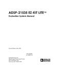
1
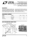
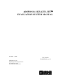
ADSP2192-12 EZ-KIT LITE EVALUATION SYSTEM MANUAL November 11, 2000 Part Number 82-000510-01 rev 1.0 Analog Devices, Inc. Digital Signal Processing Division One Technology Way Norwood, MA 02062-9106 a Copyright Information ® 2000 Analog Devices, Inc., ALL RIGHTS RESERVED. This document may not be reproduced in any form without prior, express written consent from Analog Devices, Inc. Printed in the USA. Disclaimer Analog Devices, Inc. reserves the right to change this product without prior notice. Information furnished by Analog Devices is believed to be accurate and reliable. However, no responsibility is assumed by Analog Devices for its use; nor for any infringement of patents or other rights of third parties which may result from its use. No license is granted by implication or otherwise under the patents rights of Analog Devices, Inc. Trademark and Service Mark Notice The Analog Devices logo, SHARC, the SHARC logo, VisualDSP, the VisualDSP logo, and EZ-ICE are registered trademarks; and TigerSHARC, the TigerSHARC logo, White Mountain DSP, VisualDSP++, the VisualDSP++ logo, Apex-ICE, EZ-KIT Lite, Mountain-ICE, Summit-ICE, TrekICE, and The DSP Collaborative are trademarks of Analog Devices, Inc. Microsoft and Windows are registered trademarks and Windows NT is a trademark of Microsoft Corporation. Adobe and Acrobat are trademarks of Adobe Systems Incorporated. All other brand and product names are trademarks or service marks of their respective owners. ADSP2192-12 EZ-KIT Lite Evaluation System Manual ii Regulatory Compliance The ADSP2192-12 EZ-KIT Lite has been certified to comply with the essential requirements of the European EMC directive and therefore carries the “CE” mark. Technical Certificate No: EA1209-1 Issued by: Curtis-Straus LLC 527 Great Road Littleton, MA 01460 The EZ-KIT Lite evaluation board contains ESD (electrostatic discharge) sensitive devices. Electrostatic charges readily accumulate on the human body and equipment and can discharge without detection. Permanent damage may occur on devices subjected to high energy discharges. Proper ESD precautions are recommended to avoid performance degradation or loss of functionality. Unused EZ-KIT Lites should be stored in the protective shipping package. ADSP2192-12 EZ-KIT Lite Evaluation System Manual iii TABLE OF CONTENTS 1 INTRODUCTION............................................................................................................................1-1 For More Information About Analog Devices, Inc. Products ......................................................1-2 For Technical or Customer Support .............................................................................................1-2 Purpose of This Manual ...............................................................................................................1-2 Intended Audience .......................................................................................................................1-3 Manual Contents Description.......................................................................................................1-3 Documents and Related Products.................................................................................................1-4 2 GETTING STARTED......................................................................................................................2-1 2.1 Overview......................................................................................................................................2-1 2.2 Contents of Your EZ-KIT Lite Package.......................................................................................2-1 2.3 PC Configuration .........................................................................................................................2-1 2.4 VisualDSP....................................................................................................................................2-2 2.5 Installation Procedures.................................................................................................................2-2 2.5.1 Installing the EZ-KIT Lite Hardware ...................................................................................2-2 2.5.2 Installing the EZ-KIT Lite Software ....................................................................................2-3 2.5.2.1 Installing PCI Drivers.......................................................................................................2-3 2.5.2.1.1 Installing the Windows 95 Driver ..............................................................................2-3 2.5.2.1.2 Installing the Windows 98 Driver ..............................................................................2-7 2.5.2.1.3 Installing the Windows NT Driver ...........................................................................2-10 2.5.2.1.4 Installing the Windows 2000 Driver ........................................................................2-10 2.5.2.2 Installing VisualDSP ......................................................................................................2-15 2.5.2.3 Installing the EZ-KIT Lite License Software .................................................................2-15 2.5.2.4 Installing EZ-KIT Lite Debug Software.........................................................................2-16 3 USING EZ-KIT LITE SOFTWARE ..............................................................................................3-17 3.1 Overview....................................................................................................................................3-17 3.2 Monitor Program Operation.......................................................................................................3-17 3.2.1 Monitor Resources and Restrictions...................................................................................3-17 3.2.1.1 Resources .......................................................................................................................3-17 3.2.1.2 Restrictions.....................................................................................................................3-18 3.2.2 User Programs....................................................................................................................3-20 3.2.2.1 ADSP2192-12 EZ-KIT Lite Memory Map ....................................................................3-20 3.3 Connecting With the VisualDSP Debugger ...............................................................................3-21 3.4 Using VisualDSP .......................................................................................................................3-22 3.5 Example Programs .....................................................................................................................3-22 4 WORKING WITH EZ-KIT LITE HARDWARE ............................................................................4-1 4.1 Overview......................................................................................................................................4-1 4.2 System Architecture .....................................................................................................................4-1 4.3 Board Layout ...............................................................................................................................4-2 4.4 Power Supplies.............................................................................................................................4-2 4.4.1 Power Connector..................................................................................................................4-3 4.4.2 European Power Supply Specifications................................................................................4-3 4.5 Jumpers ........................................................................................................................................4-3 4.5.1 Bus Mode Selection Jumpers (JP1)......................................................................................4-3 4.5.2 USB / Stand Alone Selection Jumpers (JP5)........................................................................4-4 4.5.3 External AC’97 Disable Jumpers (JP2, JP3)........................................................................4-5 4.5.4 Codec Line In / Microphone Jumpers (JP4).........................................................................4-5 4.5.5 JTAG Jumpers (P2)..............................................................................................................4-6 4.6 Switches .......................................................................................................................................4-6 4.6.1 Reset (SW1) .........................................................................................................................4-6 4.6.2 GPIO Interrupts (SW2, SW3) ..............................................................................................4-7 4.6.3 Communication Mode (SW4) ..............................................................................................4-7 4.7 LEDs ............................................................................................................................................4-8 1.1 1.2 1.3 1.4 1.5 1.6 ADSP2192-12 EZ-KIT Lite Evaluation System Manual iv 4.8 Serial EEPROM ...........................................................................................................................4-8 4.9 JTAG Connector ..........................................................................................................................4-9 4.10 Expansion Port Connector............................................................................................................4-9 4.11 Breadboard Area ........................................................................................................................4-10 APPENDIX A: BILL OF MATERIALS .................................................................................................. 1 APPENDIX B: SCHEMATICS ............................................................................................................... 2 ADSP2192-12 EZ-KIT Lite Evaluation System Manual v LIST OF TABLES Table 2-1: Minimum PC Configuration .......................................................................................................2-1 Table 3-1:: ADSP2192-12 EZ-KIT Lite Memory Map ..............................................................................3-21 Table 4-1: Power Connector Pin-out............................................................................................................4-3 Table 4-2: External Power Supply Specifications........................................................................................4-3 Table 4-3: BUS Pin Settings (JP1)...............................................................................................................4-4 Table 4-4: USB/Stand Alone Selection (JP5) ..............................................................................................4-5 Table 4-5: External AC’97 Settings (JP2, JP3)............................................................................................4-5 Table 4-6: Line In / Mic Settings (JP4)........................................................................................................4-6 Table 4-7: Communication Mode Switch Settings.......................................................................................4-7 Table 4-8: Suggested Serial EEPROMs.......................................................................................................4-8 Table 4-9: Expansion Connector Pinout ....................................................................................................4-10 ADSP2192-12 EZ-KIT Lite Evaluation System Manual vi LIST OF FIGURES Figure 2-1:: Windows 95 Add New Hardware Wizard detected ...................................................................2-4 Figure 2-2:: The wizard did not find an existing driver for the EZ-KIT Lite. ...............................................2-5 Figure 2-3:: In the Select Other Location dialog enter the path to the Windows 95 driver. ..........................2-5 Figure 2-4:: The wizard detects the driver information file...........................................................................2-6 Figure 2-5:: Specify the location of the device driver. ..................................................................................2-6 Figure 2-6:: Windows 95 Add New Hardware Wizard detected ...................................................................2-7 Figure 2-7:: Tell the wizard to search for the driver. ....................................................................................2-8 Figure 2-8:: Enter the path to the Windows 98 driver. ..................................................................................2-8 Figure 2-9:: The wizard detects the driver information file...........................................................................2-9 Figure 2-10:: Specify the location of the device driver. ................................................................................2-9 Figure 2-11:: The driver has been installed successfully.............................................................................2-10 Figure 2-12:: Windows 2000 Found New Hardware Wizard detected .......................................................2-11 Figure 2-13:: Tell the wizard to search for the driver. ................................................................................2-12 Figure 2-14:: Tell the wizard you will specify where to look for the driver. ...............................................2-13 Figure 2-15:: Specify the location of the device driver. ..............................................................................2-13 Figure 2-16:: The wizard detects the driver information file.......................................................................2-14 Figure 2-17:: The driver has been successfully installed.............................................................................2-15 Figure 3-1:: VisualDSP Debugger Target Selection dialog box. ................................................................3-22 Figure 4-1: Block Diagram of ADSP2192-12 EZ-KIT Lite.........................................................................4-1 Figure 4-3: BUS Pin Settings (JP1) .............................................................................................................4-4 Figure 4-4: USB/Stand Alone Selection (JP5) .............................................................................................4-5 Figure 4-5: Line In / Mic Settings (JP4) ......................................................................................................4-6 Figure 4-6: JTAG Default Jumper Settings..................................................................................................4-6 Figure 4-7: Communication Mode Switch Settings .....................................................................................4-8 Figure 4-8: JTAG Header Pinout .................................................................................................................4-9 ADSP2192-12 EZ-KIT Lite Evaluation System Manual vii 1 INTRODUCTION Thank you for purchasing the ADSP2192-12 EZ-KIT Lite evaluation kit. The evaluation board is designed to be used in conjunction with the VisualDSP® development environment and is based on the ADSP2192-12 fixed-point digital signal processor (DSP). The kit is shipped with an evaluation board and the VisualDSP software. Using the EZ-KIT Lite in conjunction with the VisualDSP environment and the debug monitor running on the EZ-KIT Lite evaluation board, gives users the ability to perform advanced application code development and debug such as: • Create, compile, assemble, and link application programs written in C and ADSP-219x assembly • Load, run, step in, step out, step over, halt, and set break points in application programs • Read and write data and program memory • Read and write core and peripheral registers • Plot memory Access to the ADSP2192-12 processor is achieved via the PC through the PCI bus communicating with the debug monitor or an optional JTAG emulator. The JTAG emulator allows the PC to perform in-circuit emulation through the processor’s JTAG interface. The JTAG emulators perform debugging at a much faster rate and provide many advanced debug features that are not available with the ADSP2192-12 debug monitor. JTAG emulators can be purchased separately through Analog Devices. The board’s features include: • Analog Devices ADSP2192-12 DSP running at 33MHz • Analog Devices AD1885 AC’97 SoundPort® codec • Jumper Selectable Line-In or Mic-In via 1/8” Stereo Jack. • 1/8” Stereo Jack for Headphone Out • Socket for Optional Serial EEPROM • PCI version 2.2 Compliant Interface • USB version 1.1 Compliant Hardware Interface with Connector • Selectable PCI (Plug-In card) Operation, USB Operation (optional), or Stand Alone Operation (optional) • Two push buttons for GPIO inputs • Two user programmable LEDs • 14 Pin Connector for JTAG Emulator Interface • User Installed expansion header • Small (2.5” x 3.5”) breadboard area with typical SMT footprints provided. ADSP2192-12 EZ-KIT Lite Evaluation System Manual 1-1 The EZ-KIT Lite board is equipped with hardware that facilitates interactive demonstrations. The push button switches and user programmable LEDs provide user control and board status. The AD1885 AC’97 SoundPort® codec provides access to an audio input (selectable as line level or microphone) and an audio output (head phone out). Additionally, by installing an optional expansion connector the user can add additional AC’97 compliant devices, as well as gaining access to the general purpose I/Os (GPIOs) pins. 1.1 For More Information About Analog Devices, Inc. Products Analog Devices is accessible on the Internet at www.analog.com. The DSP web page is directly accessible at www.analog.com/dsp. This page provides access to DSP specific technical information and documentation, product overviews, and product announcements. 1.2 For Technical or Customer Support You can reach our Customer Support group in the following ways: • Email questions to [email protected] • Contact your local Analog Devices sales office or an authorized Analog Devices distributor 1.3 Purpose of This Manual The ADSP2192-12 EZ-KIT Lite Evaluation System Manual provides directions for installing the EZKIT Lite hardware and software on your PC. Also, this manual provides guidelines for running your own code on the ADSP2192-12. ADSP2192-12 EZ-KIT Lite Evaluation System Manual 1-2 1.4 Intended Audience This manual is a user’s guide and reference to the ADSP2192-12 EZ-KIT Lite evaluation board. DSP programmers who are familiar with Analog Devices fixed-point architecture, operation, and programming are the primary audience for this manual. DSP programmers who are unfamiliar with Analog Devices DSPs can use this manual, but should supplement this manual with the ADSP2192-12 User’s Manual, the ADSP-219x Technical Reference, and the VisualDSP tools manuals. These documents describe the Analog Devices DSP architecture, DSP instruction set, and development tools. 1.5 Manual Contents Description This manual contains the following information: • Chapter 1 — Introduction Provides manual information and Analog Devices contact information. • Chapter 2 — Getting Started Provides software and hardware installation procedures, PC system requirements, and basic board information. • Chapter 3 — Using EZ-KIT Lite Software Provides information on the EZ-KIT Lite system from a software perspective, and details the monitor program and codec. • Chapter 4 — Working With EZ-KIT Lite Hardware Provides information on the Hardware aspects of the evaluation system. • Appendix A — Bill of Materials Provides a list of components used in the manufacture of the EZ-KIT Lite board. • Appendix B — Schematics Provides a resource to allow EZ-KIT Lite board level debugging or to use as a reference design. ADSP2192-12 EZ-KIT Lite Evaluation System Manual 1-3 1.6 Documents and Related Products For more information on the ADSP2192-12 and the components of the EZ-KIT Lite system, see the following documents: ADSP-2192 Reference: ADSP2192-12 User’s Manual ADSP-219x DSP Instruction Set Reference AC’97 Codec Reference VisualDSP Reference: Installation Quick Reference Card C Compiler & Library Manual for ADSP-219x Family DSPs Assembler Manual for ADSP-219x Family DSPs Product Bulletin for VisualDSP 7.0 & ADSP-219x Family DSPs C Compiler & Library Manual for ADSP-218x Family DSPs Assembler Manual for ADSP-218x Family DSPs Product Bulletin for VisualDSP 7.0 & ADSP-218x Family DSPs VisualDSP User's Guide for ADSP-21xx Family DSPs Linker & Utilities Manual for ADSP-21xx Family DSPs Part Number: 82-000510-01 82-000390-07 C00753-2.5-7100 (rev. 0) Part Number: 82-000349-06 82-000390-03 82-000390-04 82-000390-05 82-000400-03 82-000400-04 82-000400-05 82-000349-01 82-000349-02 The ADSP-219x family of processors is supported by a complete set of development tools. Software tools include a C compiler, assembler, runtime libraries and librarian, linker, simulator, and PROM splitter. These tools are described in the ADSP-219x Family Hardware and Software Development Tools Data Sheet, the VisualDSP User’s Guide & Reference, and the C Compiler Guide & Reference for the ADSP-219x Family DSPs. If you plan to use the EZ-KIT Lite in conjunction with the JTAG ICE emulator, refer to the documentation that accompanies that product. ADSP2192-12 EZ-KIT Lite Evaluation System Manual 1-4 2 GETTING STARTED 2.1 Overview This chapter provides you with the information you need to install your software and the ADSP219212 EZ-KIT Lite evaluation board. It is important that you install your software and hardware in the order presented for correct operation. 2.2 Contents of Your EZ-KIT Lite Package The EZ-KIT Lite evaluation board contains ESD (electrostatic discharge) sensitive devices. Electrostatic charges readily accumulate on the human body and equipment and can discharge without detection. Permanent damage may occur on devices subjected to high energy discharges. Proper ESD precautions are recommended to avoid performance degradation or loss of functionality. Unused EZ-KIT Lites should be stored in the protective shipping package. Your ADSP2192-12 EZ-KIT Lite evaluation board package should contain the following items. If any item is missing, contact the vendor where you purchased your EZ-KIT Lite or Analog Devices. • • • • • ADSP2192-12 EZ-KIT Lite board CD containing the EZ-KIT Lite software (PCI monitor, source, and examples) CD containing VisualDSP evaluation package for the ADSP2192-12 EZ-KIT Lite ADSP2192-12 Anomaly Sheet Registration card - please fill out and return 2.3 PC Configuration For correct operation of the VisualDSP software and the EZ-KIT Lite, your computer must have the minimum configuration shown below. Windows 95, release 95b or later, Windows 98, Windows 2000, or Windows NT, release 4.0, Service Pack 3 or later One available PCI slot Pentium processor 166 MHz or faster VGA Monitor and color video card 2-button mouse 100 MB available space 32 MB RAM CD-ROM Table 2-1: Minimum PC Configuration ADSP2192-12 EZ-KIT Lite Evaluation System Manual 2-1 2.4 VisualDSP The ADSP2192-12 EZ-KIT Lite system is shipped with the VisualDSP Integrated Development Environment (IDE), debugger and code generation tools. VisualDSP is limited in functionality by the EZ-KIT Lite license that is shipped with this product. The EZ-KIT Lite License restricts the VisualDSP debugger to only connect to the ADSP2192-12 EZ-KIT Lite evaluation board running the debug monitor via the PCI bus (no emulator or simulator support). If the full VisualDSP software suite is purchased, the user will obtain a new license string and validation code from Analog Devices that will lift the restrictions mentioned above. The basic components that are shipped with VisualDSP are: • Integrated Development Environment (IDE) — graphical interface for project management, allowing the user to set project options, access the code generation tools, and launch the debugger. • Debugger — allows the user to view the insides of the DSP and perform debug operations such as read/write memory, read/write registers, load programs, run, step, halt, and more. • ADSP-219x Family Code Generation Tools — C compiler, assembler, runtime libraries and librarian, linker, simulator, and PROM splitter. • Example Projects — Both VisualDSP and the ADSP2192-12 EZ-KIT Lite are shipped with example projects and C and Assembly source code that demonstrate various features of the tools and ADSP2192-12 fixed point DSP. 2.5 Installation Procedures The following procedures are provided to ensure reliable operation of the ADSP2192-12 evaluation board. It is important that you follow these instructions in the order presented to ensure correct operation of your software and hardware. 2.5.1 Installing the EZ-KIT Lite Hardware The ADSP2192-12 EZ-KIT Lite board is designed to run inside your personal computer. You will have to access the inside of your computer in order to install the board. Use the following steps to configure the EZ-KIT Lite: 1. Remove the EZ-KIT Lite board from the package—be careful when handling the board to avoid the discharge of static electricity, which may damage some components. 2. Make sure the switch (SW4) is in the right position for PCI operation. SW4 PCI NOTE: Do not change the position of this switch while power is applied to the board. This could damage some of the components on the board. 3. Make sure jumper JP1 is installed correctly. For PCI, JP1 should have jumpers installed on Pins 1 & 2 and Pins 3 & 4. Refer to Hardware Section (Section 4.5) of this manual if more information of jumper settings is required. ADSP2192-12 EZ-KIT Lite Evaluation System Manual 2-2 4. In order to configure your board to take advantage of the audio capabilities, use the following procedure: a) Place the appropriate jumpers on JP4. The default is Line In, and the jumpers should be placed on Pins 3 & 5 and Pins 4 & 6, respectively. b) If Mic In operation is required, then Jumpers on JP4 should be placed on Pins 1 & 3 and Pins 2 & 4, respectively. c) If more information is required, please see the Hardware Section (Section 4.5.4) of this manual. 5. Find an empty PCI slot in your computer and place the ADSP2192-12 EZ KIT Lite in the empty PCI slot. (Turn off power to your PC first) 6. Screw in bracket so that the board has a strong and direct contact to the chassis ground of the computer, and PCI contacts are seated securely. 7. If audio capabilities are being used then connect a 1/8” cable from a self powered speaker into the 1/8” Audio Jack on the bracket of the EZ-KIT Lite. This is labeled as “OUT” on the bracket. 8. Connect a Microphone or the appropriate Line In cable into the 1/8” Audio Jack on the bracket of the EZ-KIT Lite. This is labeled as “IN” on the bracket. 9. Turn on computer and verify that the PCI LED (green) on the bracket of the EZ-KIT Lite turns on. This indicates that SW4 is in correct position and that the board is successfully being powered by the computer’s PCI bus. 10. Once the PC is running, Windows should detect new hardware and will ask for the appropriate drivers for the board. Please refer to “Installing PCI Drivers” section of the “Installing the EZ-KIT Lite Software” below. This completes the hardware installation. 2.5.2 Installing the EZ-KIT Lite Software 2.5.2.1 Installing PCI Drivers You must install the drivers prior to using the PCI interface with the VisualDSP debugger. The next few sections will walk you through installing the proper driver for your system. 2.5.2.1.1 Installing the Windows 95 Driver Upon rebooting for the first time after the inserting the EZ-KIT Lite the Windows 95 Add New Hardware Wizard should start up. If it does not you may manually run it by hitting the Start button on the Windows taskbar. Then choose Settings and Control Panel. Double click on the "Add New Hardware" icon. ADSP2192-12 EZ-KIT Lite Evaluation System Manual 2-3 1. The wizard should detect the EZ-KIT Lite as shown in figure 2-1. Click Next to continue. Figure 2-1:: Windows 95 Add New Hardware Wizard detected the EZ-KIT Lite. 2. The wizard will search for a driver for the EZ-KIT Lite. If this is the first time installing the driver Windows will not find an existing one as shown in figure 2-2. Insert the EZ-KIT Lite CD into the CDROM drive. Click Other Locations… to search for the driver manually. ADSP2192-12 EZ-KIT Lite Evaluation System Manual 2-4 Figure 2-2:: The wizard did not find an existing driver for the EZ-KIT Lite. 3. The Select Other Location dialog will appear. Enter the drive letter of your CD-ROM drive followed by the path to the Windows 95 driver as shown in figure 2-3 then click OK to continue. Figure 2-3:: In the Select Other Location dialog enter the path to the Windows 95 driver. 4. The wizard should detect the driver’s information file (INF) in the Win95 folder as shown in figure 2-4. Click Finish to continue. ADSP2192-12 EZ-KIT Lite Evaluation System Manual 2-5 Figure 2-4:: The wizard detects the driver information file. 5. The wizard will prompt you for the location on the device driver as shown in figure 2-5. It is located in the same folder as the INF file. Make sure the path is entered properly and click OK to complete the driver installation. Figure 2-5:: Specify the location of the device driver. 6. Reboot the system before attempting to run the debugger over the PCI interface. ADSP2192-12 EZ-KIT Lite Evaluation System Manual 2-6 2.5.2.1.2 Installing the Windows 98 Driver Upon rebooting for the first time after the inserting the EZ-KIT Lite the Windows 98 Add New Hardware Wizard should start up. If it does not you may manually run it by hitting the Start button on the Windows taskbar. Then choose Settings and Control Panel. Double click on the "Add New Hardware" icon. 1. The wizard should detect the EZ-KIT Lite as shown in figure 2-6. Click Next to continue. Figure 2-6:: Windows 95 Add New Hardware Wizard detected the EZ-KIT Lite. 2. Select Search for the best driver for your device as shown in figure 2-7. Insert the EZ-KIT Lite CD into the CD-ROM drive and click Next to continue. ADSP2192-12 EZ-KIT Lite Evaluation System Manual 2-7 Figure 2-7:: Tell the wizard to search for the driver. 3. The wizard will prompt you for where to search. Check only Specify a location and enter the drive letter of your CD-ROM drive followed by the path to the Windows 98 driver as shown in figure 2-8 then click Next to continue. Figure 2-8:: Enter the path to the Windows 98 driver. ADSP2192-12 EZ-KIT Lite Evaluation System Manual 2-8 4. The wizard should detect the driver’s information file (INF) in the Win98 folder as shown in figure 2-9. Click Next to continue. Figure 2-9:: The wizard detects the driver information file. 5. The wizard will prompt you for the location on the device driver as shown in figure 2-10. It is located in the same folder as the INF file. Make sure the path is entered properly and click OK to complete the driver installation. Figure 2-10:: Specify the location of the device driver. 6. This will complete the driver installation as shown in Figure 2-11. Click finish to exit the wizard. ADSP2192-12 EZ-KIT Lite Evaluation System Manual 2-9 Figure 2-11:: The driver has been installed successfully. 7. Reboot the system before attempting to run the debugger over the PCI interface. 2.5.2.1.3 Installing the Windows NT Driver The Windows NT driver will automatically be installed during the installation of the EZ-KIT Lite debug software. No additional steps are needed to run under Windows NT. 2.5.2.1.4 Installing the Windows 2000 Driver Upon rebooting for the first time after the inserting the EZ-KIT Lite the Windows 2000 Add New Hardware Wizard should start up. If it does not you may manually run it by hitting the Start button on the Windows taskbar. Then choose Settings, Control Panel, then Add/Remove Hardware. Click Next and Next again to continue. 1. The wizard should detect the EZ-KIT Lite as shown in figure 2-12. Click Next to continue. ADSP2192-12 EZ-KIT Lite Evaluation System Manual 2-10 Figure 2-12:: Windows 2000 Found New Hardware Wizard detected the EZ-KIT Lite. 2. Select Search for a suitable driver for my device as shown in figure 2-13. Insert the EZ-KIT Lite CD into the CD-ROM drive and click Next to continue. ADSP2192-12 EZ-KIT Lite Evaluation System Manual 2-11 Figure 2-13:: Tell the wizard to search for the driver. 3. The wizard will prompt you for where to search as shown in figure 2-14. Check only Specify a location and click Next to continue. ADSP2192-12 EZ-KIT Lite Evaluation System Manual 2-12 Figure 2-14:: Tell the wizard you will specify where to look for the driver. 4. Enter the drive letter of your CD-ROM drive followed by the path to the Windows 2000 driver as shown in figure 2-15 then click OK to continue. Figure 2-15:: Specify the location of the device driver. 5. The wizard should detect the driver’s information file (INF) in the Win2000 folder as shown in figure 2-16. Click Next to continue. ADSP2192-12 EZ-KIT Lite Evaluation System Manual 2-13 Figure 2-16:: The wizard detects the driver information file. 6. The wizard will complete the driver installation as shown in figure 2-17. Click Finish to exit the wizard. ADSP2192-12 EZ-KIT Lite Evaluation System Manual 2-14 Figure 2-17:: The driver has been successfully installed. 7. Reboot the system before attempting to run the debugger over the PCI interface. 2.5.2.2 Installing VisualDSP This EZ-KIT Lite comes with the latest evaluation version of VisualDSP for the ADSP-219x Family DSPs. You must install this software prior to installing the EZ-KIT Lite software. Insert the VisualDSP CD into the CD-ROM drive. This will bring up the CD browser. Click on the “Install VisualDSP” option. This will launch the setup wizard. Follow this wizard with the on-screen instructions. 2.5.2.3 Installing the EZ-KIT Lite License Software Before the VisualDSP software can be used, the license software must be installed. To install the EZ-KIT Lite license software, follow these steps: 1. 2. 3. 4. Make sure VisualDSP has been installed first. Insert the VisualDSP CD into the CD-ROM drive if it is not already in the drive. Once the CD browser is on the screen select the “Install License” option. Now follow the setup wizard instructions. (Note: Make sure that you have the proper serial number located on the back of the CD holder.) ADSP2192-12 EZ-KIT Lite Evaluation System Manual 2-15 2.5.2.4 Installing EZ-KIT Lite Debug Software The EZ-KIT Lite software is supplied on a separate CD-ROM. To install the EZKIT Lite software, follow these steps: 1. 2. 3. 4. Make sure VisualDSP has been installed first. Close all Windows applications. The install will not work correctly if any VisualDSP applications are running. Insert the EZ-KIT Lite CD into the CD-ROM drive. The setup will automatically start. Follow the installation wizard by choosing the appropriate options. When the setup has completed reboot the machine. ADSP2192-12 EZ-KIT Lite Evaluation System Manual 2-16 3 USING EZ-KIT LITE SOFTWARE 3.1 Overview The EZ-KIT Lite software contains the files necessary to perform debugging over the PCI bus. Additionally, monitor source code and example programs are provided for use with the EZ-KIT Lite. The monitor software is a small debug kernel that is loaded onto each core of the ADSP2192-12 when the VisualDSP debugger is started. The monitor enables VisualDSP running on a host PC to communicate with the DSP over the PCI interface. This allows the user the ability to read/write registers, read/write memory, view hardware stacks, run, halt, step and set breakpoints among other debug activities. Understanding how the monitor works and its limitations are essential for proper operation of the EZ-KIT Lite when used with VisualDSP over the PCI interface. This chapter will provide information on how the monitor works and how to use the EZ-KIT Lite and VisualDSP to debug custom programs. Note that references to the monitor are only relevant when using the PCI interface, not the optional JTAG interface to the EZ-KIT Lite. 3.2 Monitor Program Operation As mentioned previously, the monitor is loaded onto each core when the VisualDSP debugger is first started. The monitor performs the necessary functions in order to perform debugging activities through the VisualDSP debugger such as reading/writing registers, reading/writing memory, viewing hardware stacks, running, halting, stepping and setting breakpoints. In order to carry out these functions, the monitor must use resources on the DSP such as memory and interrupts and set some restrictions upon what the user may do in their code. All of the monitor resources and restrictions are discussed below. Aside from the resources and restrictions the monitor runs transparently to the user. From the user's point of view they will see each core in either a running or halted state. While the core is running it is executing user code and while the core is halted it is really running monitor code. While in the halted state VisualDSP can request information from the monitor such as register and memory values. The source code for the monitor is included with the EZ-KIT Lite setup. The user may find the sources helpful in understanding the operation of the monitor and of the ADSP2192-12. 3.2.1 Monitor Resources and Restrictions This section will describe in detail what resources are used and what restrictions are set by the EZ-KIT Lite. It is important that the user does not tamper with the resources claimed by the monitor and that the user follow the specified restrictions when using the VisualDSP debugger and PCI interface with the EZ-KIT Lite. 3.2.1.1 Resources The monitor uses two interrupts and small blocks of data and program memory on each core. These resources are therefore not available to user programs. ADSP2192-12 EZ-KIT Lite Evaluation System Manual 3-17 The two interrupts used by the monitor are: • • Kernel interrupt (bit 2 in IMASK) Mailbox interrupt (bit 4 in IMASK) The memory ranges used by the monitor are: • • • • 0x7800 - 0x7FFF (16 bit Data Memory) 0x10008 - 0x1000B (kernel interrupt vector) 0x10010 - 0x10013 (mailbox interrupt vector) 0x13A00 - 0x13FFF (24 bit Program Memory) The debugger will catch any attempts by the user to over write the reserved regions of memory if a write is attempted with a debugger command such as a load or fill. It cannot stop user code from overwriting these regions though. After a program is loaded the interrupt vectors used by the monitor are automatically filled so that users do not need to include these vectors in their source code. 3.2.1.2 Restrictions The following restrictions should be followed to ensure proper operation of the monitor: • • • • • Only one ADSP2192-12 EZ-KIT Lite may be plugged into the PC at one time. Plugging more than one EZ-KIT Lite in at one time may cause unpredictable behavior. Do not press the reset button on the EZ-KIT Lite with the debugger open. See the section below for more information on hard reset. Pressing this button will reset the DSP and cause it to lose communication with the PCI interface on the PC. You can reset each core through the Reset command in the Debugger if necessary. This will reset the core without resetting the PCI configuration of the DSP. Disabling global interrupts will cause VisualDSP to lose all communication with the monitor. Executing the "DIS INTS;" instruction will disable global interrupts on the core. If user code executes this instruction while running, it must enable global interrupts with the "ENA INTS;" instruction in order for VisualDSP to regain communication. It is recommended that user code does not disable global interrupts. Disabling the kernel interrupt will cause VisualDSP to lose some communication with the monitor. Clearing bit 2 in the IMASK register will disable this interrupt. While disabled the user will not be able to single-step or use software breakpoints. It is recommended that user code does not disable kernel interrupts. Disabling the mailbox interrupt will cause VisualDSP to lose some communication with the monitor. Clearing bit 4 in the IMASK register will disable this interrupt. While disabled the user will not be able to halt the core. It is recommended that user code does not disable mailbox interrupts. ADSP2192-12 EZ-KIT Lite Evaluation System Manual 3-18 • • Disabling interrupt nesting will cause VisualDSP to lose communication with the monitor if the user code uses interrupts. Clearing bit 4 in the ICNTL register will disable interrupt nesting. It is recommended that the user does not disable nesting if they intend to use interrupts in their code. Do not push more than 30 values onto the PC stack. This stack is used for temporary storage upon entering the monitor. It is highly unlikely that user code will ever need more than 30 stack locations but pay closer attention when debugging C programs as the PC stack may grow without your knowledge due to function calls and library routines. Pressing the reset button on the board will reset the DSP including its PCI configuration. Do not press this with the debugger open or you will lose communication with the board. If it is necessary to perform a power on reset the user can either power down the machine or close the debugger, hit the reset button, and reload the driver. Follow the instructions below to reload the driver: For Windows 95/Windows 98 1. Right-click on My Computer and select Properties. 2. From the Device Manager tab double click DSP Emulators and highlight the ADSP2192-12 EZ-KIT Lite 3. Click Remove and then Ok to confirm it. 4. Click Refresh and Windows will detect the EZ-KIT Lite and bring up the hardware wizard. If necessary, follow the Wizard with the default values and it will find the proper driver from the previous install. 5. Once the Wizard is complete you may use the debugger again. For Window 2000 1. Only users with administrator privileges can add and remove devices, contact the administrator if necessary. 2. Right-click on My Computer and select Properties. 3. From the Hardware tab click Device Manager tab 4. Double click DSP Emulators and highlight the ADSP2192-12 EZ-KIT Lite 5. Press the delete key and then Ok to confirm it 6. Click the “Scan for hardware changes” icon and Windows will detect the EZ-KIT Lite and bring up the hardware wizard. 7. When prompted for where to look select the WINNT\INF folder so that Windows will find the INF file from the original installation. 8. Once the Wizard is complete you may use the debugger again. For Windows NT 1. Only users with administrator privileges can load the EZ-KIT Lite driver, contact the administrator if necessary. 2. From the Start menu go to Settings and choose Control Panel. 3. Double-click on Devices. 4. Scroll down to Wm2192Ez and highlight it. Click Stop and Yes to confirm it. 5. When it has stopped press Start to reload it. 6. Once started you may use the debugger again. ADSP2192-12 EZ-KIT Lite Evaluation System Manual 3-19 3.2.2 User Programs This section will provide the user with information on creating programs that will operate properly with the EZ-KIT Lite. The user will use the VisualDSP ADSP-219x code generation tools (an evaluation version is shipped with this EZ-KIT Lite) to build DSP applications and debug them with the VisualDSP debugger (also shipped with this EZ-KIT Lite). Although there are many ways to go about developing programs in the VisualDSP environment, most will include the following steps: 1. Create a new project. 2. Set target processor options. 3. Add and edit project files such as C, assembly, header, and linker description files. 4. Customize project build options such as output filenames, optimizations, etc. 5. Build a debug version of the project. 6. Debug the program with the debugger. 7. Build a release version of the project. Refer to the VisualDSP manuals and on-line help for detailed descriptions on creating projects and the ADSP-2192 data sheets and manuals for information on programming the DSPs. There are four example programs included with the EZ-KIT Lite. These are assembly and C programs designed to help the user build programs that will work properly with this EZKIT Lite and demonstrate some of its capabilities. A few things for a user to keep in mind when building projects for use with the PCI debugger interface are: • • A sample linker description file (.ldf) has been included with each example program. This file shows a possible memory allocation scheme that will not conflict with the monitor. A modified C run-time header file (2192_hdr.asm) has been included with each example C program. The code in this file performs some C initialization routines before arriving at main(). This code normally disables all interrupts but has been modified to enable the interrupts needed by the monitor (kernel and mailbox). Users should include this file with new C projects that they develop for this EZ-KIT Lite, and not include the 219x_hdr.doj library in the linker description file. 3.2.2.1 ADSP2192-12 EZ-KIT Lite Memory Map The ADSP2192-12 EZ-KIT Lite memory map is shown in the table below. Note the ranges reserved by the monitor. Memory Range 0x0000 Co r e A Co r e B 16 bit data memory (DM) 16 bit data memory (DM) 16 bit data memory (DM) 16 bit data memory (DM) 0x3FFF 0x4000 0x77FF ADSP2192-12 EZ-KIT Lite Evaluation System Manual 3-20 Memory Range 0x7800 Co r e A Co r e B Reserved for monitor Reserved for monitor 16 bit data memory (DM) Reserved 16 bit data memory (DM) Reserved 24 bit program memory ( P M) 24 bit program memory (PM) Reserved for monitor Reserved for monitor 24 bit program ROM 24 bit program ROM Reserved Reserved Shared memory Shared memory 0x7FFF 0x8000 0xBFFF 0xC000 0xFFFF 0x10000 0x139FF 0x13A00 0x13FFF 0x14000 0x14FFF 0x15000 0x1FFFF 0x20000 0x20FFF Table 3-1:: ADSP2192-12 EZ-KIT Lite Memory Map 3.3 Connecting With the VisualDSP Debugger In order to start debugging for the first time you must set up a session with the Debugger. To create a new session using the EZ-KIT Lite PCI interface follow these steps: • Press and Hold down the Control (CTRL) key. • Select the Start button on the Windows taskbar, then choose Programs, VisualDSP, Debugger. • The Session List dialog will appear. Click on New Session…. (Release CTRL key) • The Target Selection dialog will appear as shown in figure 3-1. • Under the Debug Target menu choose EZ-KIT Lite (ADSP2192-12). There is only one supported platform so you can leave the default selection in the Platform list. • Give the target a name in the Target Name field or accept the default. • Check both boxes in the Multiprocessor System list box. • Click OK to return to the Session List, make sure the new session is highlighted, and click Activate. ADSP2192-12 EZ-KIT Lite Evaluation System Manual 3-21 Figure 3-1:: VisualDSP Debugger Target Selection dialog box. 3.4 Using VisualDSP For information on operating VisualDSP, consult the On-line Help and Users manuals that are installed with VisualDSP software distribution. 3.5 Example Programs The ADSP2192-12 EZ-KIT Lite is shipped with four complete example projects, Talkthru, Dual_FIR, MPTimers, and Primes. For more detailed information regarding these projects, and the expected output of the applications, see the accompanying .txt files that are located in each project directory. These project directories can be found in: \Program Files\Analog Devices\VisualDSP\219x\EZ-KITs\2192-12\Examples ADSP2192-12 EZ-KIT Lite Evaluation System Manual 3-22 4 WORKING WITH EZ-KIT LITE HARDWARE 4.1 Overview This chapter discusses the hardware components on the ADSP2192-12 EZ-KIT Lite board. The following topics are covered: • Power Supplies in Section 4.4 • Jumpers in Section 4.5 • Switches in Section 4.6 • LEDs in Section 4.7 • Serial EEPROM in Section 4.8 • JTAG Connector in Section 4.9 • Expansion Port Connector in Section 4.10 • Breadboard Area in Section 4.11 The EZ-KIT Lite bill of materials and schematics are available at the end of this manual in Appendix A and Appendix B, respectively. 4.2 System Architecture C L O C K & R E S E T L O G IC B R E A D B O A R D U S B C o n n e c to r P C I C O N N E C T O R A R E A = A D S P 2 1 9 2 -1 2 D u a l D S P C o re A C '9 7 I N T E R F A C E N V R A M IN T E R F A C E E X P A N S IO N P O R T J T A G E m u la tio n H e a d e r G P IO P O R T E M U L A T IO N P O R T P C I/U S B IN T E R F A C E E X T E R N A L P O R T C O N N E C T O R S O p tio n a l U s e r In s ta lle d F L A G IN a n d O U T L O G IC 5 .0 V D C 3 .3 V D C S L IN H E A D C O N T E R E /M P H O N E C E IC N T O 2 .5 V D C IN E O U T O R S A D 1 8 8 5 S o u n d C o m m C O D E C O p tio n a l S E R IA L E E P R O M 5 .0 V A A D S P 2 1 9 2 -1 2 E Z -K IT B L O C K P O W E R R E G U L A T O R S & D E C O U P L IN G D IA G R A M R E V 1 .0 Figure 4-1: Block Diagram of ADSP2192-12 EZ-KIT Lite ADSP2192-12 EZ-KIT Lite Evaluation System Manual 4-1 4.3 Board Layout Figure 4-2: Layout Drawing of ADSP2192-12 EZ-KIT Lite 4.4 Power Supplies In PCI mode the ADSP2192-12 EZ-KIT Lite uses the PCI bus to supply power to the board. The 5V, 3.3V, and the 2.5V are all derived from the PCI 5V pins. The +5V analog power for the AD1885 codec is derived from the +12V supply of the PCI Bus. This keeps the Analog and Digital powers isolated from one another. In USB or Stand Alone mode the ADSP2192-12 EZ-KIT Lite uses the ADP3338 and the ADP3339 parts to regulate the 5V, 3.3V, and 2.5V digital power and +5V analog power required by the board. An external power supply, not provided in the EZ-KIT Lite, is required for USB mode or Stand Alone Mode. This power supply should not be used when using the EZ-KIT Lite via the PCI Interface. Below is a more detailed description of the power connector and power supply specifications. ADSP2192-12 EZ-KIT Lite Evaluation System Manual 4-2 4.4.1 Power Connector The power connector supplies DC voltages to the EZ-KIT Lite board. Table 4-1 shows the power connector pin out. Terminal Connection Center pin +7.5-12 VDC@2amps Outer Ring GND Table 4-1: Power Connector Pin-out 4.4.2 European Power Supply Specifications Below is the description of the Power Supply that a user must provide if the EZ-KIT Lite is used in USB mode or Stand Alone mode. DC VOLTAGE CURRENT RIPPLE DC CONNECTOR Type: 7.5V +/- 5% (Full Load) 2 Amps (Maximum Rating) 500 mV rms (Max @ Full Load) Switchcraft 760 style, FEMALE Plug Size: 5.5 (OD) V 2.5 (ID) X 9.5 (length) millimeters Polarity: Center is Positive (inside terminal) Table 4-2: External Power Supply Specifications 4.5 Jumpers 4.5.1 Bus Mode Selection Jumpers (JP1) The Bus Mode Jumpers (JP1) are used to configure the BUS [1:0] pins on the ADSP219212 DSP. In order to use the board in Stand Alone Mode the DSP must be placed in SubISA mode. Below are the different configurations for the BUS pins. ! NOTE: This Jumper should be used in conjunction with JP5 and SW4 to properly setup the board. ADSP2192-12 EZ-KIT Lite Evaluation System Manual 4-3 JP1 JP1 BUS1 BUS1 BUS0 BUS0 PCI USB JP1 JP1 Stand Alone BUS1 BUS1 BUS0 BUS0 CardBus Figure 4-3: BUS Pin Settings (JP1) BUS [1:0] 00 01 10 11 MODE *PCI CardBus (Unused) USB Sub-ISA Stand Alone * Denotes Default setting. JP1 (Pin 1 and Pin 2) IN IN OUT OUT JP1 (Pin 3 and Pin 4) IN OUT IN OUT Table 4-3: BUS Pin Settings (JP1) For more information on the ADSP2192-12 DSP Bus pins, please refer to the ADSP219212 Datasheet. 4.5.2 USB / Stand Alone Selection Jumpers (JP5) The USB / Stand Alone Jumper selection allows a user to choose between USB operation and Stand Alone operation. When in PCI mode and the switch SW4 is set accordingly, this jumper is disregarded. USB/stand alone operation are optional modes and is not supported by the supplied VisualDSP monitor based software. ! NOTE: This Jumper should be used in conjunction with JP1 and SW4 to properly setup the board. ADSP2192-12 EZ-KIT Lite Evaluation System Manual 4-4 JP5 JP5 STAND ALONE USB Figure 4-4: USB/Stand Alone Selection (JP5) MODE JP5 *Stand Alone Pins 1 and 2 USB Pins 2 and 3 PCI N/A * Denotes Default setting. Table 4-4: USB/Stand Alone Selection (JP5) 4.5.3 External AC’97 Disable Jumpers (JP2, JP3) The external AC’97 Disable Jumpers (JP2 and JP3) are used to disable the SDI1 and SDI2 pins of the AC’97 interface in the ADSP2192-12 DSP. These pins are left disabled or grounded so that the respective pins on the ADSP2192-12 DSP are not left floating. If the board is using the SDI1 and SDI2 pins via the Expansion Connector, then the respective jumper should be uninstalled. The on-board AD1885 codec will not be affected in any way by these jumpers, since the AD1885 uses SDI0 as a means of communication with the ADSP2192-12 DSP. MODE *SDI Disable SDI Enable *Denotes Default setting. SD1 (JP2) Install Uninstall SD2 (JP3) Install Uninstall Table 4-5: External AC’97 Settings (JP2, JP3) 4.5.4 Codec Line In / Microphone Jumpers (JP4) The codec Line In/ Microphone Jumpers allow a user to choose between the AD1885 being connected to a Line In signal or a Microphone signal from the Audio Connector (P4). The audio connector has an “IN” label on the edge bracket. If Microphone is selected the AD1885 provides a built-in amplifier with 20dB of gain. For more details on the AD1885 codec, please refer to the AD1885 datasheet. ADSP2192-12 EZ-KIT Lite Evaluation System Manual 4-5 JP4 JP4 LINE IN MIC IN Figure 4-5: Line In / Mic Settings (JP4) MODE JP4 MIC Connect Pins 1 & 3 and 2 & 4 *LINE IN Connect Pins 3 & 5 and 4 & 6 *Denotes Default setting. Table 4-6: Line In / Mic Settings (JP4) 4.5.5 JTAG Jumpers (P2) The JTAG Header (P2), located on the edge, should have jumpers installed when an Analog Devices JTAG emulator is not being used. This holds the JTAG signals in the correct state to allow the DSP to run free. Remove all the jumpers when connecting the emulator to the JTAG header. Below is a more detailed description of the jumper setting required to set the board to the correct configuration. JTAG 13 11 9 7 5 3 1 14 12 10 8 6 4 2 Figure 4-6: JTAG Default Jumper Settings 4.6 Switches 4.6.1 Reset (SW1) The RESET switch (SW1) located on the edge bracket should be used only if manual intervention is required for the ADSP2192-12. This switch is connected to the PORST~ signal of the DSP and causes the DSP to restart by re-executing from the internal ROM. The use of this switch is primarily intended when in Stand Alone mode. For more information on the different modes please refer to section 4.6.3 “Communication Modes.” ADSP2192-12 EZ-KIT Lite Evaluation System Manual 4-6 ! NOTE: If this switch is asserted while using the EZ-KIT Lite in PCI mode, communication to the Monitor program will be lost. This is because the DSP will restart by executing from the internal ROM. This will in effect cause the ADSP2192-12 to renegotiate with the PCI bus. A user can perform an ADSP2192-12 DSP chip reset using the Monitor program provided. This allows the user to reset the DSP without losing any PCI communication. Please refer to software section (Section 3) of this manual for more details. 4.6.2 GPIO Interrupts (SW2, SW3) The GPIO2 (SW2) and GPIO3 (SW3) are located at the top, center of the EZ-KIT Lite board. They allow a user to send a manual push button interrupt to the ADSP2192-12 DSP. If the push buttons are asserted, the respective GPIO2 and GPIO3 signals go from a logic ‘1’ (high) to a logic “0” (low). 4.6.3 Communication Mode (SW4) The Communication Mode switch (SW4), located at the top center of the EZ-KIT Lite board, is used to choose between PCI, USB, or Stand Alone operation. The switch also allows the circuitry on the board to either be powered by the PCI BUS or a user provided external power supply. The external power supply is required for both the USB and the Stand Alone operation. For more information on the power supply requirements please refer to section 4.4 of this manual. MODE *PCI SW4 Position Right Stand Alone Left USB Left Actual SW4 Pin Connection Pin 2 => Pin 1 Pin 5 => Pin 4 Pin 8 => Pin 7 Pin 11 => Pin 10 Pin 2 => Pin 3 Pin 5 => Pin 6 Pin 8 => Pin 9 Pin 11 => Pin 12 Pin 2 => Pin 3 Pin 5 => Pin 6 Pin 8 => Pin 9 Pin 11 => Pin 12 * Denotes Default setting. Table 4-7: Communication Mode Switch Settings ADSP2192-12 EZ-KIT Lite Evaluation System Manual 4-7 SW4 SW4 PCI USB / Stand Alone Figure 4-7: Communication Mode Switch Settings ! NOTE: In order to properly setup the board this switch should be configured in conjunction with configuring JP1 and JP5. For more information on jumper setting please see section 4.5 of this manual. 4.7 LEDs The ADSP2192-12 EZ-KIT Lite has a total of six LEDs for power indication, reset indication, and GPIO flag indication. The following is a more detailed description of the functionality of each respective LED. • LED1 is a dual light emitting diode package. The red light emitting diode indicates the pushbutton reset is depressed and the RESET~ is asserted. The green light emitting diode indicates the PCI bus is powering the board and SW4 is set to the right position signifying PCI operation. • LED2 is a green light emitting diode, which indicates the board is being powered by a user provided external power supply and SW4 is set to the left position signifying Standalone or USB operation. • LED3 is a green light emitting diode, which indicates the EZ-KIT Lite has power and ADSP2192-12 DSP core is being powered by 2.5V. • LED4 is a dual light emitting diode package. Both LEDs are yellow and indicate status of the GPIO1 and GPIO0 lines of the ADSP2192-12 processor. 4.8 Serial EEPROM The ADSP2192-12 EZ-Kit Lite provides socketed pins (U2) for an optional Serial EEPROM. The EEPROM is not required for operation of the board. It is only necessary if a customer wishes to modify the internal ROM code of the ADSP2192-12. If a customer wishes to install an EEPROM, then he or she can use one of the following devices or one that is electrically similar: Manufacturer: Fairchild Semiconductor Part Number: NM93C56N Microchip 93C56BP Description: 2 K-Bit 5Volt “MicroWire” Serial EEPROM 2 K-Bit 5Volt “MicroWire” Serial EEPROM Table 4-8: Suggested Serial EEPROMs ADSP2192-12 EZ-KIT Lite Evaluation System Manual 4-8 4.9 JTAG Connector The JTAG Interface allows a user to access the ADSP2192-12 DSP via the Emulation Port. Using an optional Analog Devices Emulator and optional software a user can run, test, and debug their code in any of the three modes: PCI, USB, or Stand Alone. For more information on the different types of emulator’s available please refer to: http://www.analog.com/industry/dsp/tools/selection.html The JTAG header (Figure 4-8) is the connecting point for the JTAG in-circuit emulator pod. Note that one pin is missing (pin 3) to provide keying. The mating connector should have a plug inserted in the Pin 3 location. Figure 4-8: JTAG Header Pinout ! NOTE: Power should be applied to the JTAG pod before connecting it to the EZ-KIT Lite board. For more information regarding the JTAG Interface, please refer to the Analog Devices JTAG Technical Reference: http://www.analog.com/techsupt/application_notes/EE_notes/pdf_files/ee_68.pdf 4.10 Expansion Port Connector The expansion port connector provides access to the ADSP2192-12 DSP GPIO and AC’97 signals. A user can connect up to two additional AC’97 devices using this connector and breadboard area. ! WARNING: External port loading can effect bus speed and performance. ADSP2192-12 EZ-KIT Lite Evaluation System Manual 4-9 Pin Number 1 2 3 4 5 6 7 8 9 10 11 12 13 14 15 16 17 18 Name Digital GND Digital GND ACRST~ Digital GND SYNC Digital GND SDO Digital GND SDI2 Digital GND SDI1 Digital GND SDI0 Digital GND Digital GND Digital GND BITCLK Digital GND Pin Number 19 20 21 22 23 24 25 26 27 28 29 30 31 32 33 34 35 36 Name Digital GND Digital GND GPIO7 Digital GND GPIO6 Digital GND GPIO5 Digital GND GPIO4 Digital GND GPIO3 Digital GND GPIO2 Digital GND GPIO1 Digital GND GPIO0 Digital GND Table 4-9: Expansion Connector Pinout 4.11 Breadboard Area The ADSP2192-12 EZ-KIT Lite has a 2.5”x3.5” breadboard area allowing a user to add additional thru hole or SMT components on the board. Applications could include adding more LEDs or switches to the unused GPIO Pins in the Expansion Connector, or connecting other AC’97 compliant devices to the ADSP2192-12. ! WARNING: Adding additional hardware could cause the board to malfunction. If additional devices are used, while in USB or Stand Alone modes, it is suggested power be supplied to them externally. ADSP2192-12 EZ-KIT Lite Evaluation System Manual 4-10 APPENDIX A:BILL OF MATERIALS Item # QTY Description 1 4 0.00 1/4W 5% RC05 Reference Designators R32-35 2 2 74LVC14A SOIC14 U4-5 Manufacturer/Distributor Part Number DIGI-KEY / YAGEO 0.0QBK-ND DIGI-KEY / YAGEO 0.0QTR-ND TI 74LVC14AD PHILIPS 74LVC14AD EPSON MA505 24.576M-C2 3 1 24.576MHZ SMT OSC005 Y1 DIGI-KEY SE2538CT-ND 4 1 IDC 7X2 IDC7X2 P2 SAMTEC TST-107-04-S-D-RA 5 23 0.01uF 100V 10% 1206 C31,C33,C35, AVX 12061C103KAT050M C38,C40,C42, AVX 12061C103KAT1A C57-68,C73-77 AVX 12061C103KAT2A AVX 12061C103KATATMA 6 7 2 42 8 1 1000pF 50V 5% 1206 0.1uF 50V 10% 1206 C20,C21 AVX 12061C103KATMA MUR GRM42-6X7R103K100BD AVX 12065A102JAT2A AVX 12065A102JATMA KEMET C1206C102J5GAC C13, PHILIPS 12062R104K9BB2 C17-19,C22-30, AVX 12065C104KAT1A C32,C34,C36- AVX 12065C104KAT2A 37,C39,C41, AVX 12065C104KATMA C43-56,C69-72, AVX 12065C104KATRE C78-82 KEMET C1206C104K5RAC MUR GRM42-6X7R104K050BD ADM708SAR SOIC8 U6 ANALOG ADM708SAR 9 1 AD1885JST LQFP48 U3 ADI AD1885JST 10 1 ADSP-2192-12 LQFP144 U1 ADI ADSP2192-12MKST160 11 1 ADP3338AKC-33 SOT-223 VR2 ANALOG ADP3338AKC-3.3 12 1 ADP3338AKC-5 SOT-223 VR4 ANALOG ADP3338AKC-5 13 1 ADP3338AKC-25 SOT-223 VR3 ANALOG ADP3338AKC-2.5 14 1 ADP3339AKC-5 SOT-223 VR1 ANALOG ADP3339AKC-5-REEL 15 1 PWR 2.5MM_JACK CON005 P6 SWITCHCRAFT SC1152-ND12 16 1 USB 4PIN CON009 P7 17 1 4P2T SWT011 SW4 18 1 8 PIN DIP TH-TH U2 19 1 MOMENTARY SWT010 20 2 3.5MM STEREO CON001 21 3 0.00 1/8W 5% 1206 R7,R38-39 22 2.000000 220uF 10V 20% E SWITCHCRAFT SWC RAPC712 DIGI-KEY 897-30-004-90-000000 MILL-MAX ED90003-ND DIGI-KEY EG1914-ND E-SWITCH EG4208 MILL-MAX 614-93-308-31-007 SW1 C&K TP11-SH-A-B-E P4,P5 VEN. SHO00 SJ-0359AM-5 DIGI-KEY 0.0ECT-ND DIGI-KEY 0.0ETR-ND YAGEO P0.0ETR CT5-6 YAGEO P0.0ETR-ND CORNELL DUBILIR AVS227M10E16T ADSP2192-12 EZ-KIT Lite Evaluation System Manual 1 AVX 23 24 25 2 3 1 22pF 50V 5% 805 4.7K 100MW 5% 805 120 1/8W 5% 1206 C1-2 R2-4 R17 TAJE227M010R AVX 08055A220JAT MURATA GRM40COG220J050AD MURATA GRM40COG220J050AL AVX CR21-4701F-T AVX CR21-472J-T DALE CRCW0805-472JTR AVX CR32-121JTR DALE CRCW1206-121JRT1 DALE CRCW1206-523FTR1 26 2 1.8K 1/8W 5% 1206 R20-21 AVX CR32-182J-T 27 1 2.21K 1/8W 1% 1206 R6 AVX CR32-2211F-T ROHM MCR18EZHF2211 28 2 2.2uF 35V 10% B CT10,CT11 AVX TAJB225K035R 29 7 10uF 16V 10% B CT7,CT18-23 AVX TAJB106K016R 30 1 1000 100MHZ 1.5A FER002 FER5 MURATA PLM250S40T1 31 2 2A S2A_RECT DO-214AA D1-2 GENERALSEMI S2A MICROSEMI S2A DIGI-KEY 240-1019-1-ND DIGI-KEY 240-1019-2-ND 32 33 34 35 36 7 1 1 1 1 600 100MHZ 500MA 1206 0.047UF 16V 10% 1206 1.50K 1/8W 1% 1206 YELLOW LED006 RED/GREEN LED006 FER1-4,FER6-8 C16 R37 LED4 LED1 STEWARD HZ1206B601R AVX 1206YC473KAT05 AVX 1206YC473KAT2A DIGI-KEY PCF1042CT-ND DIGI-KEY PCF1084CT-ND DALE CRCW12061501FRT1 DIGI-KEY P1.50KFCT-ND DIGI-KEY P1.50KFTR-ND DIALIGHT 552-0933 IDI CHICAGO 5670H7LC BIVAR OPTO H278CYDL LUMEX SSF-LXH250LYYD DIALIGHT 552-0711 BIVAR H278CBC LUMEX SSF-LXH250IGIGW C14-15 KEMET C1206C271K5GACTR 75 1/8W 5% 1206 R19 PHILIPS 9C12063A75R0JLRT/R 470PF 100V 10% 1206 C8-11 AVX 12061A471KAT2A C7 KEMET C1206C470K1GACTU 37 2 270PF 50V 10% 805 38 1 39 4 40 1 47PF 100V 10% 1206 KEMET C206C470K1GACTU DALE CRCW120647R5FRT1 41 1 47.5 1/8W 1% 1206 R5 DALE CRCW120647R5FTR1 42 14 10K 1/8W 5% 1206 R1,R12-15,R22-26, DALE CRCW1206-103JRT1 R28,R30,R36,R40 KOA RM73B2BT103JJRT1 DALE CR1206-1003JTR 43 1 100K 1/8W 5% 1206 R31 44 4 4.7K 1/8W 5% 1206 R8-11 45 2 680 1/8W 5% 1206 R16,R18 AVX CR32-472J-T DALE CRCW1206472JRT1 ROHM MCR18EZHMJW472 AVX CR32-681J-T ADSP2192-12 EZ-KIT Lite Evaluation System Manual 2 46 47 2 2 100 1/4W 5% 1210 GREEN-SMT LED001 R27,R29 LED2-3 DALE CRCW1206-681JRT1 KOA RM73B2BT681J PANASONIC ERJ-14YJ101 PANASONIC ERJ-14YJ101U DIGI-KEY P100VCT-ND PANASONIC LN1361C DIGI-KEY P504CT-ND DIGI-KEY P504TR-ND 48 2 SPST_MOMENTARY SWT005 SW2-3 PANASONIC EVQ-QS205K 49 10 1uF 25V 20% A CT3-4,CT8,CT9,CT1217 PANASONIC ECS-T1EY105R AVX TAJA105K020R AVX TAJA105K025R AVX TAJA105K035R 50 1 0.22uF 35V 20% A CT2 DIGI-KEY PCT6224CT-ND 51 1 QS3257Q QSOP16 U7 FAIRCHILD SEMI FST3257QSC QUALITY SEMICON QS3257Q S1011-02-ND 52 2 IDC 2X1 IDC2X1 JP2-3 DIGI-KEY 53 1 IDC 3X1 IDC3X1 JP5 SULLINS S1012-03 SULLINS PTC03SAAN 54 55 56 1 1 1 IDC 2X2 IDC2X2 IDC 3X2 IDC3X2 2.5A RESETABLE FUS001 JP1 JP4 F1 SULLINS PTC02DAAN DIGI KEY S2012-02 SULLINS PTC03DAANR DIGI KEY S2012-03-ND RAYCHEM CORP. SMD250-2 DIGI KEY SMD250CT-ND NOTE: DO NOT POPULATE P1,P3,TP1-7 & C12 ADSP2192-12 EZ-KIT Lite Evaluation System Manual 3 APPENDIX B:SCHEMATICS ADSP2192-12 EZ-KIT Lite Evaluation System Manual 2 INDEX A L audio ......................................... 1-2, 2-2, 2-3, 4-5 LEDs ..................................1-1, 1-2, 4-1, 4-7, 4-9 B M BILL OF MATERIALS..................................... 1 Board features ................................................. 1-1 Boot Mode ...................................................... 4-3 Breadboard...................................................... 4-9 Breadboard Area......................................4-1, 4-9 Bus Mode........................................................ 4-3 Memory map ................................................. 3-18 Monitor .......................................... 2-1, 3-15, 4-6 C Codec ........................................ 1-1, 1-2, 4-2, 4-5 Communication Mode..............................4-6, 4-7 Creating programs ......................................... 3-18 D Drivers ............................................................ 2-3 E EEPROM .................................................4-1, 4-8 EPROM........................................................... 4-2 Expansion Port Connector .......................4-1, 4-8 F Features........................................................... 1-1 P PC Configuration ............................................2-1 PCI ..................................................................1-1 Power connector..............................................4-3 Power Supplies.........................................4-1, 4-2 R Reset...................................... 3-16, 3-17, 4-6, 4-7 Resources ......................................................3-15 Restrictions ..........................................3 3-15, 3-16 S Schematics ......................................................1-3 Serial EEPROM .......................................1-1, 4-8 Stand Alone Mode ...................................4-2, 4-3 Switches ...................................................4-1, 4-6 System Architecture ........................................4-1 U USB.................................................................1-1 User Programs...............................................3-18 G GPIO..................................1-1, 4-6, 4-7, 4-8, 4-9 I V Installation Procedures.................................... 2-2 VisualDSP…………..ii, 1-1, 1-3, 1-4, 2-1, 2-2, 2-3, 2-14, 3-15, 3-16, 3-18, 3-19, 3-20, 4-4 J W JTAG .......................................................1-1, 4-8 JTAG Connector ............................................. 4-1 JTAG header ............................................4-6, 4-8 Jumpers ..............................2-3, 4-1, 4-3, 4-4, 4-5 Windows 2000 driver .................................... 2-12 Windows 95 driver .......................................... 2-5 Windows 98 Driver .........................................2-6 ADSP2192-12 EZ-KIT Lite Evaluation System Manual 3