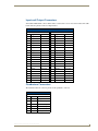
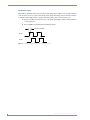
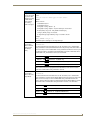
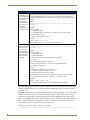
1
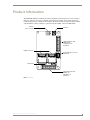
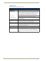
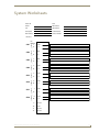
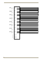
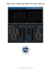
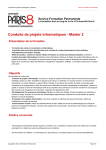
Operation/Reference Guide
NXP-CPI16
NetLinx Custom Panel Interface
Cu st o m P a n e l I n t er f a c e s
L as t R e vi s ed: 1 /1 3 /20 0 9
AMX Limited Warranty and Disclaimer
AMX warrants its products to be free of defects in material and workmanship under normal use for three (3) years from
the date of purchase from AMX, with the following exceptions:
•
Electroluminescent and LCD Control Panels are warranted for three (3) years, except for the display and touch
overlay components that are warranted for a period of one (1) year.
•
Disk drive mechanisms, pan/tilt heads, power supplies, and MX Series products are warranted for a period of one
(1) year.
•
AMX Lighting products are guaranteed to switch on and off any load that is properly connected to our lighting
products, as long as the AMX Lighting products are under warranty. AMX does guarantee the control of dimmable
loads that are properly connected to our lighting products. The dimming performance or quality cannot be
guaranteed due to the random combinations of dimmers, lamps and ballasts or transformers.
•
Unless otherwise specified, OEM and custom products are warranted for a period of one (1) year.
•
AMX Software is warranted for a period of ninety (90) days.
•
Batteries and incandescent lamps are not covered under the warranty.
This warranty extends only to products purchased directly from AMX or an Authorized AMX Dealer.
All products returned to AMX require a Return Material Authorization (RMA) number. The RMA number is obtained
from the AMX RMA Department. The RMA number must be clearly marked on the outside of each box. The RMA is
valid for a 30-day period. After the 30-day period the RMA will be cancelled. Any shipments received not consistent
with the RMA, or after the RMA is cancelled, will be refused. AMX is not responsible for products returned without a
valid RMA number.
AMX is not liable for any damages caused by its products or for the failure of its products to perform. This includes any
lost profits, lost savings, incidental damages, or consequential damages. AMX is not liable for any claim made by a
third party or by an AMX Dealer for a third party.
This limitation of liability applies whether damages are sought, or a claim is made, under this warranty or as a tort claim
(including negligence and strict product liability), a contract claim, or any other claim. This limitation of liability cannot
be waived or amended by any person. This limitation of liability will be effective even if AMX or an authorized
representative of AMX has been advised of the possibility of any such damages. This limitation of liability, however, will
not apply to claims for personal injury.
Some states do not allow a limitation of how long an implied warranty last. Some states do not allow the limitation or
exclusion of incidental or consequential damages for consumer products. In such states, the limitation or exclusion of
the Limited Warranty may not apply. This Limited Warranty gives the owner specific legal rights. The owner may also
have other rights that vary from state to state. The owner is advised to consult applicable state laws for full
determination of rights.
EXCEPT AS EXPRESSLY SET FORTH IN THIS WARRANTY, AMX MAKES NO OTHER WARRANTIES,
EXPRESSED OR IMPLIED, INCLUDING ANY IMPLIED WARRANTIES OF MERCHANTABILITY OR FITNESS FOR
A PARTICULAR PURPOSE. AMX EXPRESSLY DISCLAIMS ALL WARRANTIES NOT STATED IN THIS LIMITED
WARRANTY. ANY IMPLIED WARRANTIES THAT MAY BE IMPOSED BY LAW ARE LIMITED TO THE TERMS OF
THIS LIMITED WARRANTY.
Table of Contents
Table of Contents
Product Information ...........................................................................................1
Specifications............................................................................................................ 2
Installation ..........................................................................................................3
Input and Output Connectors ................................................................................... 3
Quadrature Connectors ............................................................................................ 3
Quadrature Inputs........................................................................................................... 4
Programming ......................................................................................................5
Levels........................................................................................................................ 5
Send_Commands ...................................................................................................... 6
System Worksheets ..........................................................................................11
NXP-CPI16 NetLinx Custom Panel Interface
i
Product Information
Product Information
The AMX NXP-CPI16 is a NetLinx panel device that allows system integrators to connect switches,
indicators, and rotary encoders to a NetLinx control system. Providing contact closure inputs and
feedback outputs for up to 16 buttons, the miniature PC board contains two 20-pin headers for ribbon
cable installation or direct mounting to a printed circuit board. FIG. 1 shows an NXP-CPI16.
Indicator
power connector
ID button
20-pin I/O header with
Outputs 9-16
and Inputs 9-16
(Header 2)
ICSNet connectors
6-pin quadrature connector
(Header 3)
Status LED
20-pin I/O header with
Outputs 1-8
and Inputs 1-8
(Header 1)
FIG. 1 NXP-CPI16
NXP-CPI16 NetLinx Custom Panel Interface
1
Specifications
The table below lists the NXP-CPI16 specifications.
NXP-CPI16 Specifications
Power Requirement
12 VDC (300 mA max.)
Input Connectors:
Indicator Power
Two-pin 3.5 mm captive-wire. This connector is used to supply a higher voltage
and more current to the power pins of Header 1 and Header 2. The external
supply connected to the two-pin captive-wire must be greater than +12 V. If the
external supply voltage is less than that, the ICSNet supply (+12 V) will be
used for the Power pin of the I/O connectors (not the external supply).
Closure Inputs
16 closure inputs activated with a GND or TTL Low (< 0.8 V). Inputs are sampled approximately every 10 msec and are debounced in software.
Rotary Encoder Inputs
2 quadrature inputs on a 2 x 3 header with a +5 V supply pin (supplying up to
100 mA) and a GND pin.
ICSNet
2 RJ-45 connectors for ICSNet connection
ID Button
Generates an event from the CPI16 to allow you to assign new Device numbers, using ID mode in the NetLinx Studio software program.
LED
ICSP status indicator (green)
Open Collector Outputs
16 open-collector outputs, acting as a switch to ground, up to 100 mA. Outputs
can be connected to voltages ranging between 0 V and +28 V. Each output is
updated approximately every 10 msec.
Dimensions (HWD)
2.75" x 1.75" x 0.062" (69.85 mm x 44.45 mm x 1.557 mm)
Weight
8.10 oz (229.6 g)
Accessories
• 6-pin header with 3 feet (0.91 m) of ribbon cable
• Two mating 20-pin headers, each with 3 feet of ribbon cable attached
• One green 2-pin 3.5 mm pitch captive wire connector for external indicator
power.
2
NXP-CPI16 NetLinx Custom Panel Interface
Input and Output Connectors
To install the NXP-CPI16, connect ribbon cables or a PC board to one or more of the headers. The table
below shows the pinouts for the two 20-pin headers.
I/O Connector Pinouts
Header 1
Header 2
Pin
Signal
Function
Pin
Signal
Function
1
Output 1
OC to Ground
1
Output 9
OC to Ground
2
Output 2
OC to Ground
2
Output10
OC to Ground
3
Output 3
OC to Ground
3
Output 11
OC to Ground
4
Output 4
OC to Ground
4
Output 12
OC to Ground
5
Output 5
OC to Ground
5
Output 13
OC to Ground
6
Output 6
OC to Ground
6
Output 14
OC to Ground
7
Output 7
OC to Ground
7
Output 15
OC to Ground
8
Output 8
OC to Ground
8
Output 16
OC to Ground
9
Ground
Signal Ground 9
Ground
Signal Ground
10
Power
Power Supply
Power
Power Supply
11
Ground
Signal Ground 11
Ground
Signal Ground
10
12
Ground
Signal Ground 12
Ground
Signal Ground
13
Input 1
Logic Input
13
Input 9
Logic Input
14
Input 2
Logic Input
14
Input 10
Logic Input
15
Input 3
Logic Input
15
Input 11
Logic Input
16
Input 4
Logic Input
16
Input 12
Logic Input
17
Input 5
Logic Input
17
Input 13
Logic Input
18
Input 6
Logic Input
18
Input 14
Logic Input
19
Input 7
Logic Input
19
Input 15
Logic Input
20
Input 8
Logic Input
20
Input 16
Logic Input
Quadrature Connectors
The table below lists the connector pinouts for the quadrature connector.
Quadrature Connector Pinouts
Header 3
Pin
Signal
Function
1
Ground
Signal ground
2
1A
Encoder # 1, Input A
3
1B
Encoder # 1, Input B
4
2A
Encoder # 2, Input A
5
2B
Encoder # 2, Input B
6
+5 V
Encoder power
NXP-CPI16 NetLinx Custom Panel Interface
3
Quadrature Inputs
By default, the quadrature inputs expect the phase relationship, shown in FIG. 2, for a clockwise rotation
of the encoder to generate a positive level change. If the phase relationship does not match the example,
a clockwise rotation will generate a negative level change. This can be corrected in two ways:
Inputs A and B can be wired in reverse so the phase relationship is obtained at the quadrature
encoder input pins.
Insert a QDIR Send_Command in the NetLinx program.
200 nsec minimum
Input A
Input B
FIG. 2 Quadrature inputs phase relationship for clockwise rotation
4
NXP-CPI16 NetLinx Custom Panel Interface
Programming
Programming
There are two modes of Channel Assignments: Discrete Output and Default Mode. Both modes are set
using the ‘STATUS-ON’ and ‘STATUS-OFF’ commands. Discrete Output mode should be used if
channel status feedback for the outputs needs to be separate from the inputs. The tables below provide
channel assignment information on both modes. For more information, refer to the
Send_Commands section on page 6.
Status ON Mode Channel Assignment
I/O
Corresponding Channel
Assignment
Inputs 1 - 8
Channels 1 - 8 (On/Push/Off/Release)
Outputs 1 - 8
Channels 9 - 16 (On/Off only)
Inputs 9 - 16
Channels 17 - 24 (On/Push/Off/Release)
Outputs 9 - 16 Channels 25 - 32 (On/Off only)
Status OFF Mode Channel Assignment
I/O
Corresponding Channel
Assignment
Inputs 1 - 8
Channels 1 - 8 (Push/Release only)
Outputs 1 - 8
Channels 1 - 8 (On/Off only)
Inputs 9 - 16
Channels 9 - 16 (Push/Release only)
Outputs 9 - 16 Channels 9 - 16 (On/Off only)
Levels
By default all levels have a data type of byte (8-bits), which gives a range of 0-255 for the Level Value.
The ‘LVL_SZ’ Send_Command sets the size of the value for levels 1 - 4. It is important that the variable
in any SEND_LEVEL command and CREATE_LEVEL statement in the NetLinx program match the
data type selected by the ‘LVL_SZ’ Send_Command. Incorrect levels may occur if the data types do not
match.
The input and output Level values will not be sent until a ’LEVON’ command
message is received by the CPI16. A transmission of levels will cease after the
receipt of a ’LEVOFF’ command.
The values of Levels 1 and 2 (quadrature inputs) will be sent whenever the input changes.
Levels
Level
Function
1
Quadrature Input 1
2
Quadrature Input 2
3
Bargraph 1 (Outputs 1 - 8) - if configured for bargraph mode
4
Bargraph 2 (Outputs 9 - 16) - if configured for bargraph mode
NXP-CPI16 NetLinx Custom Panel Interface
5
Send_Commands
Use the Send_Commands listed in the table below to program the NXP-CPI16.
Send_Commands
BMODE
Configures either
set of 8 outputs as
an 8-segment bargraph display.
Syntax:
‘BMODE <bargraph #> <bargraph mode>’
Variables:
Where <bargraph #>
1 - Selects bargraph 1 (outputs 1 - 8)
2 - Selects bargraph 2 (outputs 9 - 16)
Where <bargraph mode>
0 - normal bar mode
1 - normal dot mode (only one peak LED on at a time)
2 - special bar mode (a level of 1 - 15 still has the first LED on)
3 - special dot mode (a level of 1 -15 still has the first LED on)
4 - inverse normal bar mode
5 - inverse normal dot mode
6 - inverse special bar mode
7 - inverse special dot mode
8 - individual element, discrete mode
9 - inverse individual element, discrete mode
OFF - disables bargraph mode [default]
The command is used to configure either set of 8 outputs as an 8-segment bargraph display. By default, Bargraph mode is OFF and all outputs are discrete outputs that are controlled via CHANNEL ON/OFF messages. If this command is received, the selected bank
of 8 outputs will respond according to the selected mode.
In modes 8 and 9, the discrete LEDs that are ON correspond to the bit mask sent via a
Send_Level command. For Example:
SEND_LEVEL CPI16, 3, $5A
Turns on LEDs 2, 4, 5, and 7 of bargraph #1.
Example:
SEND_COMMAND ‘BMODE 1 0’
Reconfigures Outputs 1 - 8 such that they now act as an 8-segment bargraph.
LEVOFF
Keeps any level
value from transmitting.
LEVON
Syntax:
‘LEVOFF’
The NXP-CPI16 will not transmit any level value messages after the receipt of this command until the receipt of another LEVON command.
Syntax:
‘LEVON’
The NXP-CPI16 transmits level value messages after the receipt of this command.
Send_Commands (Cont.)
LVL_SZ
The default is byte (8-bits), which yields a range of 0 - 255 for the level value.
Sets the size (data
type) of the value
that will be used by
the NXP-CPI16
when receiving
and sending
LEVEL messages.
Syntax:
‘LVL_SZ <level #> <data type of level value>’
Variables:
Where <level #>
1 - Quadrature Input 1
2 - Quadrature Input 2
3 - Bargraph 1 (using outputs 1 - 8)
4 - Bargraph 2 (using outputs 9 - 16) and <data type of level value>
B - Byte (8-bits); range of 0 - 255 [default level data type]
I - Integer (16 bits); range of 0 - 65,535
S - Signed Integer (signed 16-bits); range of -32,768 to 32,767
Example:
SEND_COMMAND ’LVL_SZ 2 S’
Quadrature Input 2's data type is now Signed Integer.
STATUS-OFF
Puts the NXPCPI16 in Default
Mode (non-Discrete Output
Mode).
Syntax:
‘STATUS-OFF’
The CPI16 remembers the last Mode it was set for. Therefore, once a ’STATUS-OFF’
Send_Command is received, Default Mode becomes the power-up mode of the CPI16. It
is not necessary to send a ’STATUS-OFF’ Send_Command each time the device is powered. Once the CPI16 is programmed for Default Mode, it remains in that mode until a
’STATUS-ON’ Send_Command is received; see chart below.
Inputs 1 - 8
Channels 1 - 8 (Push/Release only)
Outputs 1 - 8
Channels 1 - 8 (On/Off only)
Inputs 9 - 16
Channels 9 - 16 (Push/Release only)
Outputs 9 -16
Channels 9 - 16 (On/Off only)
It is not necessary to send a 'STATUS-OFF' Send_Command each time the device is
powered. Once the CPI16 is programmed for Default Mode, it will remain in Default
Mode until a 'STATUS-ON' Send_Command is received.
STATUS-ON
Puts the NXPCPI16 in Discrete
Output Mode.
Syntax:
‘STATUS-ON’
The CPI16 remembers the last Mode it was set for. Therefore, once a ’STATUS-ON’
Send_Command is received, Discrete Output Mode becomes the power-up mode of the
CPI16. It is not necessary to send a ’STATUS-ON’ Send_Command each time the
device is powered. Once the CPI16 is programmed for Discrete Output Mode, it remains
in that mode until a ’STATUS-OFF’ Send_Command is received.; see chart below.
Inputs 1 - 8
Channels 1 - 8 (On/Push/Off/Release)
Outputs 1 - 8
Channels 9 - 16 (On/Off only)
Inputs 9 - 16
Channels 17 - 24 (On/Push/Off/Release)
Outputs 9 -16
NXP-CPI16 NetLinx Custom Panel Interface
Channels 25 - 32 (On/Off only)
7
Please note that the actual direction of rotation for a positive level change will depend
Controls the direc- upon the phase relationship of the outputs on the quadrature encoder selected. If the
tion of rotation that correct phase relationship is not met, it may be necessary to send a CCW (counterwill correspond to a clockwise) QDIR command to get a positive level change for a clockwise rotation of the
encoder.
positive level
QDIR
increase on the
quadrature inputs.
The default rotation for both
quadrature inputs
is CW (clockwise).
Syntax:
‘QDIR <input #> <direction or rotation for a positive level
change>’
Variables:
Where <input#>
1 - Quadrature Input 1
2 - Quadrature Input 2 and <direction of rotation for a positive level change>
CW - Clockwise rotation
CCW - Counter-Clockwise rotation
Example:
SEND_COMMAND ‘QDIR 2 CCW’
The quadrature input 2 is set for counter-clockwise rotation.
QRATE
Sets the number of
pulses that must
be seen on the
quadrature input in
a given direction in
order to reach the
maximum attainable level.
Syntax:
‘QRATE <input #> <# of pulses that represent the maximum level
allowed>’
Variables:
Where <input #>
1 - Quadrature Input 1
2 - Quadrature Input 2
and <# of pulses that represent the maximum level allowed>
0-32,767
This number should be calculated as follows:
Pulses = <pulses/rotation> x <# of rotations to reach maximum level>
The default for Pulses is 24.
Example:
Pulses/rotation = 50 (get from encoder data sheet)
# of rotations desired to reach max. level = 2
Therefore, the equation reads: 50 x 2 = 100.
This value will be used to scale the level reported to the NetLinx master as follows:
level change = (<maximum level> / <Pulses>) x <current pulse count>
Example:
SEND_COMMAND ‘QRATE 1 100’
The full range of quadrature input 1 is set for 100 pulses from the encoder.
The NXP-CPI16 uses input channels to report user input on the contacts or switches attached to the input
terminals. Output channels are used to turn on the lamp or LED display devices to indicate the button
status to the user.
The NXP-CPI16 default mode is STATUS-OFF, and in this mode the programmer cannot poll the NXPCPI16 to determine the state of the output channel. This is because in this mode the output and input
channels use the same number assignments. Inputs are sent by the NXP-CPI16 only as input changes.
When set for STATUS-ON mode the output channels are assigned a different channel number than the
input channels. This allows the programmer to monitor the status of an output channel. However the
channel offset must be accommodated in the programming code.
Statements such as this example can be used in a program.
IF[CPI16,25]
8
(* output channel assigned to input channel 9 on P3 connector *)
NXP-CPI16 NetLinx Custom Panel Interface
Each of the two 20-pin connectors is assigned a group of 8 input and output channels. The table below
shows the relation of input and output channels in the STATUS modes.
Input/Output STATUS Mode
Mode
Connector
STATUS-OFF (default)
STATUS-ON
Inputs
J3
Chan 1-8
Chan 1-8
J4
Chan 9-16
Chan 17-24
J3
Chan 1-8
Chan 9-16
J4
Chan 9-16
Chan 25-32
Outputs
The NXP-CPI16 may be configured to default to STATUS-ON mode using the following method. The
commands can force a change to the mode no matter what default mode is configured for the device.
STATUS-ON Mode:
Remove R7 (1K ohm) resistor OR short across R8 for STATUS-ON mode. Firmware remains the same
for standard and STATUS-ON mode NXP-CPI16 units.
NXP-CPI16 NetLinx Custom Panel Interface
9
10
NXP-CPI16 NetLinx Custom Panel Interface
System Worksheets
System Worksheets
Dealer ID
Date
Dealer
PO Number
Job
SO Number
Description
Serial Number
Rev Number
Device Number
Header 1
CH1
Pin
Number
1
CH2
CH3
13
In
2
Out
14
In
3
Out
15
4
CH4
Out
In
Out
16
In
5
Out
17
In
CH5
6
CH6
18
7
CH7
19
8
CH8
Out
In
Out
In
Out
20
In
9
Ground
10
Power
11
Ground
12
Ground
Header 2
NXP-CPI16 NetLinx Custom Panel Interface
11
CH9
CH10
CH11
1
13
In
2
Out
14
In
3
Out
15
4
CH12
Out
In
Out
16
In
5
Out
17
In
CH13
6
CH14
18
7
CH15
19
8
CH16
Out
In
Out
In
Out
20
In
9
Ground
10
Power
11
Ground
12
Ground
AMX. All rights reserved. AMX and the AMX logo are registered trademarks of AMX. AMX reserves the right to alter specifications without notice at any time.
©2009
1/09
It’s Your World - Take Control™
3000 RESEARCH DRIVE, RICHARDSON, TX 75082 USA • 800.222.0193 • 469.624.8000 • 469-624-7153 fax • 800.932.6993 technical support • www.amx.com