1
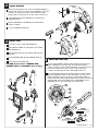
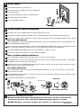
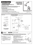
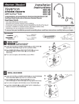
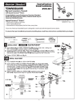
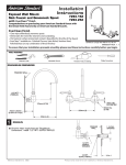
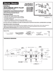
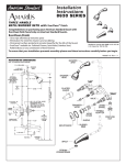
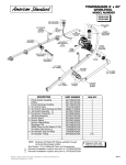
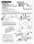
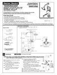
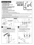
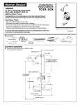
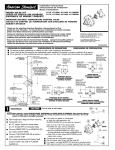
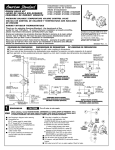
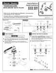
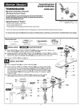
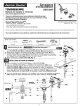
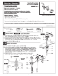
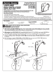
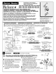
Installation
Instructions
2555.602
TOWNSQUARE
PRESSURE BALANCING BATH AND
SHOWER-Built-in Diverter for TUB FILLER
with EverClean™ Finish
Congratulations on purchasing your American Standard faucet with
EverClean finish found only on American Standard faucets.
EverClean Finish
• One wipe effortlessly removes spots
• Eliminates the need for cleaners and scrubbing
Certified to comply with ANSI A112.18.1
• Permanent surface protectant remains beautiful
for the life of the faucet
M 9 6 8 7 8 9 R e v. 1 . 2
• EverClean™ available on: Polished Chrome, Satin Nickel,
Stainless Steel, Polished Brass (or any combination of these finishes)
To ensure that your installation proceeds smoothly-please read these instructions carefully before you begin.
Required Tools
ROUGHING-IN DIMENSIONS
To assure proper positioning in relation to wall, note
roughing-in dimensions.
1-5/8" TO 3-1/4"
FINISHED WALL
Phillips Screwdriver
1
1/2" I.P.S.
2" REF.
OPTIONAL TO
FINISHED FLOOR
USUALLY BETWEEN
65'' AND 78''
Flat Blade Screwdriver
OUTLETS 1/2" NPT
8" REF.
74" FOR
HEAD CLEARANCE
SHW
Plumbers' Putty or Caulking
"SEE ILLUSTRATION"
5-5/8"
7-1/2"
TUB
18"
OPTIONAL
1-3/4"
7-1/4" REF.
Channel Locks
1/2" NPT
TOP OF
TUB RIM
Adjustable Wrench
1
ROUGHING-IN
4"
1
INLETS
1/2" NPT
5-5/8"
THREADED INLETS (STOPS)
BOTTOM OF
TUB
CAUTION
Turn off water at main supply.
5
NOTE When soldering, remove PLASTER GUARD, CARTRIDGES and CHECK STOPS (IF PRESENT). When finished soldering,
flush valve body, replace cartridges, check stops (if present) and plaster guard to continue installation. Use thread
sealant or Teflon tape on threaded connections.
See Roughing-in diagram before starting.
Connections are:
1/2" female NPT for threaded inlets
Connect RISER PIPE (1) to MANIFOLD (2)
top outlet marked "SHR".
Connect TUB FILLER PIPE (3) at bottom
outlet marked "TUB".
For proper positioning the finished wall
must be within side wall of PLASTER
GUARD (4).
1
If the valve is installed on a fiberglass
or other thin wall application, the
2
PLASTER GUARD (4) can be used as a support.
Cut a 4" dia. hole in the shower stall.
Drill two additional 1" holes to allow access
to the stops.
HOT
Remove PLASTER GUARD (4), rotate 180˚
so that indicated screw holes fit MANIFOLD (2).
Push CAP on valve, place ESCUTCHEON on and
3
attach with screws.
Connect hot and cold water supplies.
Cap off shower pipe (5) and tub filler pipe (6).
For support, use pipe BRACES (7) secured to wooden braces.
With valve turned off, turn on water supplies. Check for leaks.
7
COLD
6
4
2
INSTALL DIVERTER
DIVERTER
PORT
When finished tiling the wall, remove PLASTER GUARD (1).
Remove two screws that secure the DIVERTER LID (2) and
remove Lid. Inspect the inside surface of diverter port.
Diverter port must be free of any dirt. Clean if necessary.
2
Install DIVERTER (3) with SCREWS (4) removed from
DIVERTER LID (2).
Operate DIVERTER (3). DIVERTER (3) should slide in
and out smoothly.
Push on DIVERTER COVER (5).
3
4
5
3
INSTALL TRIM
1
Push CAP (1) over VALVE CARTRIDGE (2).
Mount ESCUTCHEON (3) and gasket to valve body
with SCREWS (4).
Remove PIPE CAPS (5) from shower pipe and tub
filler pipe.
Install SHOWER ARM (6) and SHOWER HEAD (7).
Install TUB FILLER SPOUT (8).
CAUTION: Protect finish on SHOWER ARM,
SHOWER HEAD and TUB SPOUT when installing.
4
ADJUST HOT LIMIT STOP
By restricting HANDLE rotation and limiting the amount of hot
water allowed to mix with the cold, the HOT LIMIT SAFETY
STOP (1) reduces risk of accidentalscalding. To set the maximum
hot water temperature of your faucet, all you need to do
is adjust the setting on the HOT LIMIT SAFETY STOP (1).
Turn CARTRIDGE STEM (2) to the OFF position (coldest setting)
before making adjustment to HOT LIMIT STOP (1). Use a flat
blade screwdriver to pry free the HOT LIMIT SAFETY STOP (1).
Pull forward and rotate counterclockwise one number to limit hot
water temperature. Use ARROW (3) on CARTRIDGE (4) and
NUMBERS (5) on HOT LIMIT STOP (1) for indication.
7
6
5
3
5
15
1
311
97531
0
1
1
4
3
3
2
2
2
1
3
1
5
1
1
9
7
5
3
4
1
HOTTER
(Smaller Numbers)
0 1 3 5 7 9 11 13 15
5
1
3
1
5
1
1
8
COLDER
(Larger Numbers)
0 1 3 5 7 9 11 13 15
1
9
7
5
3
4
1
5
M 9 6 8 7 8 9 R e v. 1 . 2
5
INSTALL HANDLE
Install HANDLE BUSHING (1) onto CAP (2).
7
Find correct position of HANDLE (3) and push HANDLE (3)
onto VALVE STEM (4).
Install HANDLE SCREW (5) and push in INDEX CAP (6).
Check proper operation of HANDLE.
6
5
Screw on DIVERTER KNOB (7).
1
4
2
3
6
TO GAIN ACCESS TO VALVE FOR SERVICING
Pull INDEX CAP, unscrew HANDLE SCREW and pull HANDLE off valve stem.
Remove two SCREWS holding ESCUTCHEON and remove ESCUTCHEON. Remove COVER by pulling straight out.
Shut off water supply by either closing off main water supply, or closing off the hot and cold CHECK STOPS on valve, if present.
VALVE LEAKS WHEN SHUT OFF
Remove CARTRIDGE (1) by removing CARTRIDGE SCREWS (2). Remove three SCREWS (3) from FIXATION RING (4) and
pull out PRESSURE BALANCING (5) unit.
Clean SEALS (9) on base of CARTRIDGE (1). Check base of PRESSURE BALANCING UNIT (5) and clean O-RINGS (6). Remove
CAPS (7) and check O-RINGS on inside of CAPS (7). Clean inside sealing surfaces of VALVE BODY (8).
Re-assemble PRESSURE BALANCING UNIT (5) and CARTRIDGE (1). Tighten all screws.
Turn on water supply and see above for installing TRIM and HANDLE.
UNABLE TO MAINTAIN CONSTANT TEMPERATURE
Remove PRESSURE BALANCE UNIT (5). Remove CAPS (7) and clean valve thoroughly.
Examine balancing unit and check condition of O-ring on end of piston. Piston should move back and forth. Order Repair
Part M952100-0070A if balancing unit is defective.
Replace CAPS (7) and install PRESSURE BALANCE UNIT (5). Make sure inlets line up with two holes in bottom of casting.
Top flange should butt-up against top of casting.
BACK TO BACK INSTALLATION
Remove PRESSURE BALANCE UNIT (5). Rotate PRESSURE BALANCE UNIT (5) 180˚ so that the inlets face up and the
large outlet port faces down.
Push PRESSURE BALANCE UNIT (5) in casting make sure inlets line up with holes in bottom of casting. Top flange should
butt up against top of casting.
Reassemble FIXATION RING (4) and CARTRIDGE (1).
4
ROTATE 180˚
LARGE OUTLET
1
5
6
8
7
INLETS
5
BACK TO BACK INSTALLATION
3
9
7
2
EverClean™ Finish Care Instructions
American Standard’s EverClean finish will wipe clean with a soft, dry cloth. A soft cloth with
clean water may also be used, if desired. No additional cleaning products are required.
DO NOT USE: Soaps, acid, polish, abrasives, harsh cleaners, or a cloth with a coarse surface.
M 9 6 8 7 8 9 R e v. 1 . 2