1
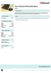
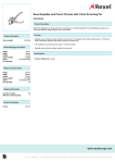
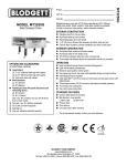
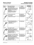
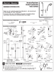
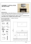
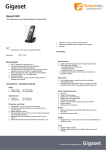
Installation
Instructions
2064.724
ONE SHOWER SYSTEM
Thank you for selecting American-Standard...the benchmark
of fine quality for over 100 years.
To ensure that your installation proceeds smoothly--please
read these instructions carefully before you begin.
Certified to comply with ANSI A112.18.1
M968927 Rev. 1.1
Recommended Tools & Materials
10mm (3/8)
Drill Bit
Pencil
Hammer
Electric Drill
Level
ROUGHING-IN DIMENSIONS
FINISHED WALL
95mm
(3-3/4)
54mm
(2-1/8)
38mm
(1-1/2)
Phillips Screwdriver
Teflon Tape
1/2" NPT
76mm
(3)
41mm
(1-5/8)
32mm
(1-1/4)
13mm
(1/2)
53mm
(2-1/16)
620mm
(24-3/8)
586-595mm
(23-1/8, 23/3/8)
(48" - 60") (OPTIONAL)
TO FINISHED FLOOR
1/2" NPSM HOSE
CONNECTION
RUBBER GASKET
FINISHED
WALL
60mm
(2-3/8")
65mm
(2-1/2")
19mm
(3/4)
203mm
(8")
33.5mm
(1-3/16D.)
OPTIONAL TO
FINISHED FLOOR
USUALLY BETWEEN
915mm TO 1219mm
(48)
(36)
96mm
(3-3/4)
25mm
(1")
59"
151mm
(6")
FINISHED FLOOR
1/2" NPSM
1
INSTALL WALL SUPPLY
CAUTION
Turn off hot and cold water
supplies before beginning.
1
Supply to WALL SUPPLY (1) is 1/2" NPT. See rough-in above for detailed information.
Install RUBBER SEAL (2) onto WALL SUPPLY (1).
Apply sealant or teflon tape to threads of 1/2" NPT supply nipple. Thread WALL SUPPLY (1)
onto supply nipple making a water tight seal. WALL SUPPLY (1) with RUBBER SEAL (2)
should be tight against finished wall.
2
1/2" NPT
APPLY SEALANT
OR TEFLON TAPE
2
INSTALL WALL BRACKETS
The ADJUSTABLE SHOWER BAR (1) works best if secured to a wall stud or cross brace
within the wall, using the SCREWS (2) supplied.
If the ADJUSTABLE SHOWER BAR (1) is to be installed on a tile the ANCHORS (3) and
SCREWS (2) should be used.
Determine desired height and location (optional) and mark a center line. If MOUNTING
SUPPORT (4) is secured to a stud or cross brace drill small pilot holes for SCREWS (2).
IMPORTANT: Make sure that vertical center line is level.
591mm
(23-1/4)
For installations on tiled walls: Use ANCHORS (3) and SCREWS (2) for securing MOUNTING
SUPPORT (4) to finished wall. The diameter and depth of the mounting hole should be
10mm (3/8”) dia. and 50mm (2”) deep. Insert the the ANCHORS (3) and tap them with
hammer until flush with face of finished wall.
Install RUBBER WASHER (5) in recess of MOUNTING SUPPORT (4). Secure
MOUNTING SUPPORT (4) to wall with SCREWS (2).
3
INSTALL ADJUSTABLE SHOWER BAR
4
5
3
C/L
2
Install ADJUSTABLE SHOWER BAR (1) onto installed MOUNTING SUPPORTS (4).
Push ADJUSTABLE SHOWER BAR (1) flush against finished wall and tighten
SET SCREWS (5) with (2.5mm) HEX WRENCH (7) supplied to secure
ADJUSTABLE SHOWER BAR (1) to wall.
RECESS IN
MOUNTING
SUPPORT
5
13
FINISHED WALL
591mm
(23-1/4)
7
2
11
12
1
591mm
(23-1/4)
4
5
3
FROM CENTER TO
CENTER OF WALL
BRACKETS
10
8
9
4
C/L
INSTALL HOSE AND HAND SHOWER
Install SEAL (8) into COUPLING NUT (9). Connect COUPLING NUT (9) to WALL SUPPLY NIPPLE (10) and tighten.
INSTALL second SEAL (11) into SPRAY HOSE END (12) and connect HAND SHOWER (13) to SPRAY HOSE END (12).
Hand tighten.
M968927 Rev. 1.1