1
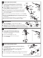
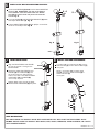
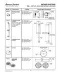
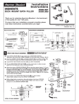
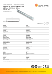
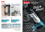
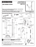
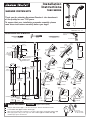
Installation
Instructions
1662 SERIES
SHOWER SYSTEM KITS
Thank you for selecting American-Standard...the benchmark
of fine quality for over 100 years.
To ensure that your installation proceeds smoothly--please
read these instructions carefully before you begin.
Certified to comply with ANSI A112.18.1
M 9 6 8 6 3 7 R ev 1. 4
Recommended Tools & Materials
6mm (15/64")
Drill Bit
Hammer
Phillips Screwdriver
Pencil
Electric Drill
ROUGHING-IN DIMENSIONS
13mm
(1/2")
1/2" NPT
53mm
(2-1/16")
(48" - 60")
(OPTIONAL)
TO FINISHED
FLOOR
1/2" NPSM HOSE
CONNECTION
RUBBER GASKET
FINISHED WALL
1498mm
(59")
65mm
(2-1/2")
1/2" NPSM
1660.505
1660.502
1/2" NPSM
1/2" NPSM
1660.225
549mm
(21-5/8")
116mm
(4-5/8")
266mm
(10-1/2")
115mm
(4-1/2")
76mm
(3")
1
INSTALL WALL SUPPLY
247mm
(9-3/4")
252mm
(9-7/8")
1660.628
1/2" NPSM
CAUTION
65mm
(2-1/2")
94mm
(3-3/4")
94mm
(3-3/4")
86mm
(3-3/8")
1/2" NPSM
1/2" NPSM
81mm
(3-1/4")
86mm
(3-3/8")
FINISHED FLOOR
1660.743
1660.143
1/2" NPSM
OPTIONAL TO FINISHED FLOOR
USUALLY BETWEEN
915mm TO 1525mm
(60")
(36")
121mm
(4-3/4")
258mm
(10-1/8")
265mm
(10-3/8")
1660.843
25mm
(1")
98mm
(3-7/8")
122mm
(4-3/4")
900mm
122mm
(35-3/8") (4-3/4")
600mm
(23-5/8")
A950646
67mm
(2-5/8")
146mm
(5-3/4")
85mm
(3-3/8")
1660.236
65mm 849mm
(2-1/2") (33-3/8")
70mm
(2-3/4")
191mm
(7-1/2")
120mm
(4-3/4")
1/2" NPSM
240mm
(9-1/2")
45mm
(1-3/4")
250mm
(9-7/8")
1660.500
127mm
(5")
82mm
(3-1/4")
1660.550
85mm
(3-3/8")
240mm
(9-1/2")
24mm
(1")
57mm
(2-1/4")
42mm
(1-5/8")
32mm
(1-1/4")
239mm
(9-3/8")
1660.741
1660.638
1/2" NPSM
1/2" NPSM
Turn off hot and cold water
supplies before beginning.
90mm
(3-1/2")
1
Supply to WALL SUPPLY (1) is 1/2" NPT. See rough-in above for detailed information.
Install RUBBER SEAL (2) onto WALL SUPPLY (1).
Apply sealant or teflon tape to threads of 1/2" NPT supply nipple. Thread WALL SUPPLY (1)
onto supply nipple making a water tight seal. WALL SUPPLY (1) with RUBBER SEAL (2)
should be tight against finished wall.
2
1/2" NPT
APPLY SEALANT
OR TEFLON TAPE
2
INSTALL LOWER SUPPORT BRACKET
The SLIDE BAR works best when secured to the wall studs or
cross brace using the WOOD SCREWS. If a mounting into the
studs is not possible, use appropriate wall fasteners to provide
secure installation.
Mark a vertical center line in the location you wish to install the
SLIDE BAR. NOTE: The height from the finished floor is optional.
See rough-in drawing for suggested dimensions.
VERTICAL
C/L
Fig. A
HORZ.
C/L
1
Fig. B
OPTIONAL
TO FINISHED
FLOOR
Determine desired height from the finished floor to the lower support
and mark a horizontal center line. Place the MOUNTING BRACKET (1)
on the center lines, with a pencil mark the location on the mounting
holes to be drilled. Fig. A.
FINISHED
FLOOR
Using 15/64" diameter drill. Drill two mounting holes 1" max. deep. Fig. B.
2
Install the two ANCHORS (2) provided into the mounting holes. (Use a hammer
to lightly tap ANCHORS (2) into place.) Make sure they are installed flush with
the finished wall.
1
3
Place the MOUNTING BRACKET (1) over the ANCHORS (2) and secure the
MOUNTING BRACKET (1) with the SCREWS (3) provided. Fig. C.
3
Fig. C
Fig. A
INSTALL SLIDE BAR
1
Slide the COVER (1) onto the MOUNTING BRACKET (2) flush
against the wall. Fig. A.
SLOT
Install the bottom of SLIDE BAR (3) into the MOUNTING BRACKET (2).
IMPORTANT: The slot at the bottom of the slide bar must face toward the
wall. Rotate the slide bar until it locks into place and cannot be turned. Fig. B.
4
LOCATE UPPER MOUNTING BRACKET
Install the upper MOUNTING BRACKET (1) onto the
SLIDE BAR (2). Align the MOUNTING BRACKET (1)
with center lines and mark the center mounting hole
with a pencil as shown. Fig. A.
Remove the SLIDE BAR (2) and set a side.
3
2
Fig. B
2
1
2
Fig. B
Fig. A
Using 15/64" diameter drill bit, drill mounting hole
1" max. deep. Fig. B.
5
INSTALL UPPER MOUNTING BRACKET
Fig. A
Install the ANCHOR (1) provided into the mounting hole. Make sure
it is installed flush with the finished wall. (Use a hammer to lightly tap
ANCHOR (1) into place.)
3
1
2
Place the MOUNTING BRACKET (2) over the ANCHOR (1) and secure
the MOUNTING BRACKET (2) with the SCREW (3) provided.
NOTE: Do not tighten fully.
4
Slide the MOUNTING BRACKET (2) up against the bottom of the mounting slot..
Slide the COVER (4) onto the MOUNTING BRACKET (2) flush against the wall.
2
BOTTOM OF MOUNTING SLOT
Fig. B
M 9 6 8 6 3 7 R ev 1. 4
6
INSTALL SLIDE BAR INTO MOUNTING BRACKETS
Install the SLIDE BAR (1) back into the lower MOUNTING
BRACKET (2). IMPORTANT: The slot at the bottom
of the slide bar must face toward the wall. Rotate
the slide bar until it locks into place and cannot be
turned. Fig. A.
3, 4
5
SLIDE
BAR
TOP
Push top COVER (3) and MOUNTING BRACKET (4) down
onto top of SLIDE BAR (1). Fig. A.
Tighten MOUNTING SCREW (5) with phillips screw driver
to secure assembly to wall. Fig. B
Fig. A
Fig. B
1
SLOT
2
7
8
FINISH INSTALLATION
Align the ESCUTCHEON and SPACER
so that the spacer is sitting on the
ESCUTCHEON.
3
SPACER
ESCUTCHEON
Rotate the upper ESCUTCHEON and
SPACER (1) on SLIDE BAR (2) until
the three snap arms align with the
holes in the cover. Push ESCUTCHEON
and SPACER (1) into COVER (3)
until it snaps in place.
INSTALL HOSE AND HAND SHOWER
1
Install SEAL (1) into COUPLING NUT (2). Connect
COUPLING NUT (2) to WALL SUPPLY NIPPLE (3)
and tighten.
2
INSTALL second SEAL (4) into SPRAY HOSE
END (5) and connect HAND SHOWER (6) to
SPRAY HOSE END (5).
Hand tighten.
Repeat above steps to snap the lower
ESCUTCHEON andSPACER (4) into place.
6
4
5
4
3
1
2
CARE INSTRUCTIONS:
DO: SIMPLY RINSE THE PRODUCT CLEAN WITH CLEAR WATER. DRY WITH A SOFT COTTON FLANNEL CLOTH.
DO NOT: DO NOT CLEAN THE PRODUCT WITH SOAPS, ACID, POLISH, ABRASIVES, HARSH CLEANERS, OR A CLOTH
WITH A COARSE SURFACE.
M 9 6 8 6 3 7 R ev 1. 4