1
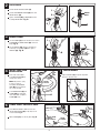
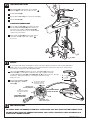
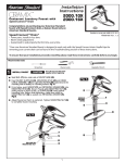
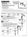
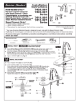
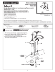
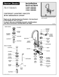
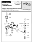
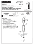
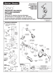
Installation
Instructions
SEVA
1480.110
1480.115
Centerset Lavatory Faucet with
SpeedConnect™ Drain
Congratulations on purchasing your American Standard
faucet with Speed Connect drain, a feature found only on
American Standard faucets.
Speed Connect™ Drain*
Certified to comply with ANSI A112.18.1
• Fewer parts, installs in less time
M 9 6 8 3 0 5 R E V. 1 . 1
• Never needs adjustment
• Guaranteed to seal properly the first time, every time.
*Your new American Standard faucet is designed to work only with the Speed Connect drain. Heplful tips for
removing your current drain can be found in the Troubleshooting section of these instructions.
To ensure that your installation proceeds smoothly-please read these instructions carefully before you begin.
Required tools
Screwdriver
1
Channel Locks
Tubing Cutter
Adjustable Wrench
INSTALL FAUCET
CAUTION
Turn off water at
main supply.
Turn off hot and cold water supplies before beginning.
Note: Putty is not required unless mounting surface
is uneven.
Apply a bead of PUTTY along the edge of
the underside of the BODY (1) if required.
Fig. A.
Insert FAUCET (1) and CABLE CONNECTOR (2) through
mounting holes of Sink or mounting surface. Fig. A.
Assemble LOCKNUTS (3) onto SHANKS (4) from under
side of Sink. Hand tighten firmly. Fig. B.
(HAND TIGHTEN)
1
4
PUTTY
(IF REQUIRED)
3
POP-UP
CABLE
4
Fig. B.
SINK OR
MOUNTING
SURFACE
3
2
2
1
2
POP-UP DRAIN
Fig. A.
Remove CLEAR PLASTIC COVER (1).
Fig. B.
1
Remove CARDBOARD SPACER (2) from under
DRAIN POP-UP (3).
DRAIN
BODY
3
Tighten TAILPIECE (4) on DRAIN BODY before
installing DRAIN BODY. Fig. B.
4
2
3
REMOVE FLANGE
Fig. A.
Thread FLANGE (1) counter-clockwise and remove
FLANGE (1) and FOAM GASKET (2) from drain
body. Fig. A.
Fig. B.
1
Thread LOCKNUT (3) clock-wise to bottom of
drain body. Push GASKET (4) down against
LOCKNUT (3). Fig. B.
4
2
3
4
INSTALL DRAIN FROM
BELOW FIXTURE
From under side of SINK
install DRAIN BODY (1) up
through drain outlet.
Note: No plumber’s putty
or caulk is required.
The CABLE ATTACHMENT
POINT (2) must face towards
the rear of the SINK.
REAR
OF
SINK
4
TIGHTEN LOCKNUT
Tighten LOCKNUT (1) firmly with Adjustable
Wrench or Channel Locks.
DRAIN
OUTLET
3
FLANGE GASKET AND POP-UP KNOB
1
1
Install FOAM GASKET (3) and
FLANGE (4) onto drain body
from above SINK and tighten
FLANGE (4) firmly.
6
5
2
Fig. A.
Fig. B.
Check DRAIN FLANGE in SINK to ensure that
WHITE FOAM GASKET (3) is fully compressed
and not visible. Fig. A.
POP-UP KNOB (1) must be fully down. Fig. B.
DOWN
1
WHITE FOAM
GASKET
NOT VISIBLE
DRAIN
FLANGE
M 9 6 8 3 0 5 R E V. 1 . 1
2
7
ATTACH CABLE CONNECTOR
Fig. A.
Fig. B.
Thread CABLE CONNECTOR (1) clockwise
onto DRAIN BODY CONNECTION (2) and
hand tighten. Fig. A.
1
Your new POP-UP DRAIN installation is
now complete. Fig. B.
Note: Tailpeice on pop-up drain is 1-1/4” O.D.
Fig. B.
2
1-1/4” O.D.
8
CHECK OPERATION OF POP-UP
Operate LIFT KNOB (1) to verify that STOPPER (2) opens and
closes.
1
Note: If STOPPER (2) does not open and close properly then
refer to the “troubleshooting section” of these instructions.
2
9
MAKE WATER SUPPLY AND WASTE CONNECTIONS
NOTE: FLEXIBLE SUPPLIES OR BULL-NOSE RISERS MUST BE
PURCHASED SEPARATELY.
Connect water supply to FAUCET (1) with 1/2" IPS FLEXIBLE
SUPPLIES (2) or 3/8" O.D. BULL-NOSE RISERS (3).
Use adjustable wrench to tighten connections. Do not over tighten.
Be careful not to kink copper supply when bending. Use tubing
cutter to cut to proper length.
Connect 1-1/4” O.D. tailpiece on POP-UP DRAIN to
waste outlet.
1/2" PIPE
THREAD
1
COUPLING
NUT
2
FLEXIBLE
SUPPLIES
3
3/8 O.D.
BULL-NOSE
RISERS
3/8” COMPRESSION
CONNECTION
COMPRESSION
NUT
FERRULE
HOT
COLD
M 9 6 8 3 0 5 R E V. 1 . 1
3
10
TEST INSTALLED FITTING
1
With HANDLE (1) in OFF position, turn on WATER
SUPPLIES (2) and check all connections for leaks.
Remove AERATOR (3).
4
Operate both HANDLE (1) to flush water lines thoroughly.
Replace AERATOR (3).
CHECK DRAIN CONNECTIONS
3
Operate POP-UP KNOB (4) and fill lavatory with water.
Check that DRAIN STOPPER (5) makes a good seal
and retains water in SINK. If DRAIN STOPPER (5)
does not seal properly, please refer to Troubleshooting
section in these instructions.
Release POP-UP KNOB (4) down and check all drain
connections and "P" trap for leaks. Tighten
if necessary.
5
WASTE
OUTLET
2
2
11
“P” TRAP
SERVICE
By restricting handle rotation and limiting the amount of hot water allowed to mix with the cold, the HOT LIMIT SAFETY
STOP reduces risk of accidental scalding. To set the maximum hot water temperature of your faucets, all you need to
do is adjust the setting on the HOT LIMIT SAFETY STOP.
Loosen SET SCREW (2) with 2.5mm hex wrench. Pull HANDLE (1) off valve stem.
Pull off CAP (3). Use a flat blade screwdriver or your fingers to pull up and rotate
red HOT LIMIT SAFETY STOP (4). Follow Step "A" or "B" to adjust min./max. discharge
temperature. "0" being the hottest to "7" the coldest temperature setting.
Factory set at "0".
Replace ESCUTCHEON CAP (3),
HANDLE (1), tighten HANDLE
SCREW (2).
1
2
3
PRY RED RING FORWARD
"A" AND ROTATE COUNTERCLOCKWISE ONE CLICK
"A"
0
1
4 5
6 7
"B"
"A"
3
"B"
PRY RED RING FORWARD
AND ROTATE CLOCKWISE
2
TEMPERATURE
SETTING NUMBERS
ADJUSTMENT WHEN
WATER IS TOO HOT
"B"
ADJUSTMENT WHEN
WATER IS TOO COLD
4
"RED RING"- HOT
LIMIT SAFETY STOP
12
CARE INSTRUCTIONS:
DO: SIMPLY RINSE THE PRODUCT CLEAN WITH CLEAR WATER. DRY WITH A SOFT COTTON FLANNEL CLOTH.
DO NOT: DO NOT CLEAN THE PRODUCT WITH SOAPS, ACID, POLISH, ABRASIVES, HARSH CLEANERS, OR A
CLOTH WITH A COARSE SURFACE.
4
M 9 6 8 3 0 5 R E V. 1 . 1