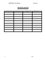
1
PRODUCT MANUAL
MX28B-PDF
POWER DISTRIBUTION FRAME
APC DC Network Solutions Inc.
11035 Switzer Avenue
Dallas, TX 75238
800-800-4APC
PART NUMBER 990-9132
MX28B-PDF Product Manual
Revision A
REVISION HISTORY
Revision
A
2
Date
26 Jan 2001
By
JNF
Description
Initial release
APC
Revision A
MX28B-PDF Product Manual
TABLE OF CONTENTS
1.
GENERAL INFORMATION............................................................................................................. 4
2.
1.1 Introduction .............................................................................................................................. 4
1.2 Precautions .............................................................................................................................. 4
1.3 Inspection Upon Receipt Of Goods ......................................................................................... 4
1.3.1 General ............................................................................................................................ 4
1.3.2 Visible External Damage ................................................................................................. 4
1.3.3 Concealed Damage......................................................................................................... 5
1.3.4 Return of Damaged Goods.............................................................................................. 5
SYSTEM OVERVIEW AND TECHNICAL DESCRIPTION ............................................................. 6
2.1 General System Overview ....................................................................................................... 6
2.2 General System Specifications................................................................................................ 6
2.2.1 Input –48 VDC Bus......................................................................................................... 7
2.2.2 Circuit Breaker Tiers........................................................................................................ 7
2.2.3 Circuit Breakers ............................................................................................................... 7
2.3 INDICATORS AND ALARMS .................................................................................................. 8
2.3.1 Meters ..………..………………………………………………………………………………..8
2.3.2 Alarm Relay ..................................................................................................................... 9
3.
INSTALLATION PROCEDURES1………………………………………………………………………10
3.1 Preparation ............................................................................................................................ 10
3.1.1 Recommended Tools .................................................................................................... 10
3.1.2 Recommended Test Equipment.................................................................................... 10
3.1.3 Equipment Inspection .................................................................................................... 10
3.1.4 Safety Precautions ........................................................................................................ 10
3.1.5 Room/Locations............................................................................................................. 10
3.1.6 Mounting ....................................................................................................................... 11
3.2 Input power connections........................................................................................................ 11
3.3 DC System Grounding........................................................................................................... 12
3.4 Circuit Breaker Installation..................................................................................................... 13
3.5 Load connections................................................................................................................... 13
4.
CUSTOMER SERVICE AND SUPPORT ...................................................................................... 14
5.
WARRANTY PROVISIONS .......................................................................................................... 14
5.1
5.2
5.3
5.4
APC
General Provisions ................................................................................................................ 14
Warranty returns .................................................................................................................... 14
Warranty Repair or Replacement .......................................................................................... 15
EXCLUSIONS AND LIMITATIONS ....................................................................................... 15
3
MX28B-PDF Product Manual
Revision A
1. GENERAL INFORMATION
1.1.
INTRODUCTION
The MX28B Power Distribution Frames (PDF) from APC DC Network Solutions Inc. possesses
unique features that make them easy to install, maintain and upgrade.
Sales support for purchases, proposals, after-sales support, etc. is provided by APC DC
Network Solutions Inc. sales and service offices.
APC DC Network Solutions Inc. provides nationwide 24 hour, 7 day service response by
dialing:
(800) 800- 4APC
This service will answer your call, gather specific service information, and ask a qualified service
representative to contact you as quickly as possible (refer to Section 4).
APC DC Network Solutions Inc. is Located at 11035 Switzer Avenue, Dallas, Texas, 75238.
Phone: (214) 652-4040; FAX: (214) 342-5027.
1.2.
PRECAUTIONS
It is extremely important to read, understand, and strictly follow the proper
INSTALLATION PROCEDURES in Section 3. In particular, note the SAFETY
PRECAUTIONS in Section 3.1.4:
If any precautions are not clearly understood, or special local codes exist, contact your
nearest APC DC Network Solutions Inc. representative or the APC DC Network Solutions
Inc. offices at (800) 800- 4APC for clarification.
Also, it is the customer’s responsibility to ensure that all applicable federal, state and local
regulations and industry guidelines are complied with for correct installation of this power
system.
1.3.
INSPECTION UPON RECEIPT OF GOODS
1.3.1 General
Precautions have been taken to pack the equipment properly for shipment to ensure safe
arrival. However, upon receipt, please inspect the entire shipment, including any boxes or
crates, for evidence of damage that may have occurred during transit. Also, confirm that the
material received matches the packing slip.
1.3.2 Visible External Damage
It is the responsibility of the person receiving the shipment IMMEDIATELY upon taking delivery
(while the carrier representative is still on site) to inventory and inspect all materials against the
provided bill of lading or weigh bill.
4
APC
Revision A
MX28B-PDF Product Manual
Please be sure that all items are accounted for, including the number of pallets and the
quantity of accessory and/or component boxes. Also note any visible external damage that
may have occurred during transit.
If damage has occurred, or the quantity of items is not correct:
•= Make a descriptive notation on the delivery receipt before signing.
•= File a damage report with the carrier that delivered the shipment.
1.3.3 Concealed Damage
Within 15 days of receipt, unpack the power system and equipment received from APC
DC Network Solutions Inc. and check for concealed damage. Check the materials
received against the detailed packing list to verify the quantity and condition as complete
and satisfactory.
Again, note any damage to the internal packing material and/or material shortages.
If damage or shortage is noted:
•= Request an inspection by the carrier.
•= File a concealed damage claim; and/or
•= File a material shortage claim with your APC DC Network Solutions Inc.
Representative.
DELAY IN NOTIFYING THE CARRIER MAY RESULT IN LOSS OF RIGHT TO
REIMBURSEMENT FOR DAMAGES OR LOSS.
Should you have any questions concerning potential damages or should you
experience a lack of cooperation from your carrier, call APC DC Network Solutions
Inc. at (800) 800- 4APC.
1.3.4 Return of Damaged Goods
Should equipment be damaged and require return to APC DC Network Solutions Inc. for
repair, the APC DC Network Solutions Inc. service representative will provide instructions
along with a valid RMA (Returned Material Authorization) number to facilitate return of the
damaged goods to the APC DC Network Solutions Inc. repair center.
It is important that proper steps as outlined in Section 1.3.2 and 1.3.3 above are followed
carefully. Your APC DC Network Solutions Inc. representative will assist you, if required,
in obtaining proper disposition of an initial delivery return issue.
However, a valid RMA number must be obtained before returning any equipment to
APC DC Network Solutions Inc.
APC
5
MX28B-PDF Product Manual
Revision A
2. SYSTEM OVERVIEW AND TECHNICAL DESCRIPTION
2.1 GENERAL SYSTEM OVERVIEW
The Power Distribution Frame (PDF) provides for distribution of –48 VDC power through circuit
breakers. The PDF consists of a rack with three power distribution cabinets. Each cabinet can
hold up to 48 circuit breakers on two separate tiers for a total of 144 breakers.
2.2 SYSTEM SPECIFICATIONS
The system is available in six configurations:
Part Number Tier Locations Breakers
Feeds
AAB-0583-01
A,D
48
2 Separate
AAB-0583-02
A,B,D,E
96
4 Separate
AAB-0583-03
A,B,C,D,E,F
144
6 Separate
AAB-0583-11
A,B
48
One
AAB-0583-22
A,B & D,E
96
Two
AAB-0583-33 A,B,C & D,E,F
144
Two
A
D
B
E
C
F
Figure 2-1 System Configurations
6
APC
Revision A
MX28B-PDF Product Manual
2.2.1 Input –48 VDC Bus
All six busses can be isolated, or tied together with splice plates depending on customer desires.
Splice Plates
Installed
Without Splice
Plates
Figure 2-2 Bus Bars
2.2.2 Circuit Breaker Tiers
Each circuit breaker tier provides positions for mounting 24 plug-in circuit breakers. Each tier bus
is connected to the –48 VDC input bus with each side having an ampacity of 600 amperes.
2.2.3 Circuit Breakers
The PDF utilizes plug-in magnetic circuit breakers to supply loads from the –48 VDC bus. Each
circuit breaker has auxiliary contacts that close if the breaker trips, thus enabling monitoring of
fault conditions. Circuit breakers are available with ratings from 1 – 100 amperes (see Table 2-1)
Plug-in circuit breakers rated at 60A or more require two mounting positions. They are available in
kit form (see kit selection information in Table 2-2). These kits include the breaker and all
necessary mounting hardware.
APC
7
MX28B-PDF Product Manual
Revision A
BREAKER
RATING
PART NUMBER
BREAKER
RATING
PART NUMBER
1A
FFA-0014
20 A
FFA-0018
3A
FFA-0015
30 A
FFA-0019
5A
FFA-0016
40 A
FFA-0020
10 A
FFA-0017
50 A
FFA-0025
15 A
FFA-0028
Table2.1 Plug-in Circuit Breakers
#10 stud
5/8” centers
#10 stud
3/4” centers
¼” stud
1” centers
60A
70A
80A
100A
FFA-0021-1
FFA-0022-1
FFA-0023-1
FFA-0024-1
FFA-0021-2
FFA-0022-2
FFA-0023-2
FFA-0024-2
FFA-0021-3
FFA-0022-3
FFA-0023-3
FFA-0024-3
Table 2.2 Circuit Breaker kits
2.3 Indicators and Alarms
2.3.1 Meters
The MX28B-PDF power distribution frame has a meter assembly, P/N OM-9275 located below
the top cabinet door, for displaying bus voltage and current. A six position rotary switch selects
which breaker tier is to be monitored. Voltmeter accuracy is ±0.5%; ammeter accuracy is ±1.0%.
Also displayed are power and circuit breaker trip status.
Figure 2-3 Meter Assembly
8
APC
Revision A
MX28B-PDF Product Manual
2.3.2 Alarm Relay
There is an alarm relay, K-1 located on the center of the meter panel that energizes if any circuit
breaker trips within the PDF. Form C contacts from this relay are available via connector J-9
located at the center of the circuit board. If the PDF is being powered by an APC MX28B power
system, these contacts can be monitored by connecting them to the “external Alarm Inputs”
available in the controller
J-9
K-1
Figure 2-4 Alarm Relay Circuit
MECHANICAL SPECIFICATIONS:
•= Dimensions
•= Weight
•= Color
84” high x 23” wide x 23” deep
475 Lbs (approximate)
Dawn Gray
ENVIRONMENTAL:
•= Temperature
•= Humidity
•= Altitude
APC
-20°C to +65°C Operating
-40°C to +85°C Storage
0% to 85% non-condensing operating
0% to 95% non-condensing storage
Up to 3000 meters operating
Up to 10,000 meters storage
9
MX28B-PDF Product Manual
Revision A
3. INSTALLATION PROCEDURES
3.1 PREPARATION
3.1.1 Recommended Tools
Tools required for installation:
•= Standard selection of customary insulated hand tools used by qualified technicians.
•= An appropriate drill to drill holes in the floor to anchor the plant.
•= A crimping device for compressing lugs not already crimped.
3.1.2 Recommended Test Equipment
Test equipment required for installation:
•= Digital Multimeter
3.1.3 Equipment Inspection
Remove equipment from packing material and inspect for shipping damage to verify the
safety and operational suitability for the installation site. [Refer to Section 1.3.]
3.1.4 Safety Precautions
WARNING:
Hazardous energy levels are present on bare conductors in the –48 VDC distribution
connection area of the plant. Accidental shorting of distribution conductors can cause
arcing and high currents that can cause serious burns or other physical harm.
It is recommended that:
Any jewelry, rings or watches be removed while working on this equipment. Handles of
all wrenches, screwdrivers, cutters and pliers be insulated. Shafts of screwdrivers be
wrapped in electrical tape or otherwise insulated.
3.1.5 Room/Locations
NOTE: The Power Distribution Frame is to be installed in a room, vault, or similar
enclosure that is accessible only to qualified persons in accordance with
the NEC (National Electrical Code) or the authority having jurisdiction.
Prior to installation, drawings, floor loading requirements, and grounding schemes should
all be verified. Installation drawing number INS-0017 is available from APC DC Network
Solutions in Dallas TX.
10
APC
Revision A
MX28B-PDF Product Manual
3.1.6 Mounting
The box frame housing is self-supporting, but designed to be bolted to the floor of the housing
structure. The figure below shows the footprint of the box frame and the mounting points with
dimensions (shown in inches). Consult the system design specifications to see if it is necessary to
electrically isolate the frame from the floor structure. This is required in many installations. Insulator
kit, part number AAB-0597 is available if required.
FRONT
23.0
1.50
11.5
11.5
Figure 3-1 Mounting diagram
3.2 INPUT POWER CONNECTIONS
The PDF –48VDC input bus offers multiple connection points for both 1 inch or 1.75 inch on
center lugs. The +48VDC return bus has connection points at both the top and bottom for 1 inch
and 1.75 inch lugs. If splice plates are used, they also are configured with holes for connection.
3.3 DC SYSTEM GROUNDING
THE POSITIVE LOAD CONNECTION (RETURN BUS) FOR THE POWER DISTRIBUTION
FRAME MUST BE CONNECTED TO THE FACILITY MASTER STATION GROUND.
DETAILS FOR THIS CONNECTION SHOULD BE PROVIDED IN THE SITE ELECTRICAL
GROUNDING PLANS.
APC
11
MX28B-PDF Product Manual
Revision A
+48V Bus
-48V Bus without
splice plate
-48V Bus
Splice plate
With splice plates
without splice plates
Figure 3-2 Bus Bars
3.4 CIRCUIT BREAKER INSTALLATION
Use diagonal cutters to cut the metal web of the breaker panel “knock-outs” at the desired breaker
locations.
Note: Plug-in Breakers (60 A – 100A) require two mounting positions and a breaker
adapter kit.
The breakers are installed by snapping the top terminal onto the upper bus bar and rotating the
unit down until the second terminal snaps onto the breaker termination post as shown in Figure 33. The breaker alarm terminals are designed to make contact with the alarm terminal board as
the breaker is snapped into place.
**** CAUTION ****
During breaker installation, carefully align the alarm terminals with
the alarm terminal board to avoid breaker terminal damage.
12
APC
Revision A
MX28B-PDF Product Manual
Knock-outs
Figure 3-3: Installation of Circuit Breakers
3.5 LOAD CONNECTIONS
Connection for –48VDC loads are made from standard size #10-32 two-hole lugs on 5/8” centers
located directly next to the corresponding circuit breaker. The load returns connect to the –48VDC
load return bus located behind each row of circuit breakers. The load return bus provides threaded
holes for terminating 2-hole lugs. The return bus has provisions for 25 #10-32 lugs on 5/8” centers
and 10 ¼”-20 lugs on 1” centers (all pairs can not be used simultaneously). Each DC load run should
be bundled with its return for as much of the run length as possible. (Figure 3-4)
Load supply
Load return
Figure 3-4 load connections
APC
13
MX28B-PDF Product Manual
Revision A
4. CUSTOMER SERVICE AND SUPPORT
APC DC Network Solutions Inc. manufactures the MX28B line of Power Plants and provides
customers with complete product and systems support and service. APC DC Network Solutions Inc.
has a network of factory trained service technicians. The service organization is on call 24 hours a
day, 365 days a year.
If you experience a problem with your APC power system that requires our attention, contact
APC DC Network Solutions Inc. at
(800) 800- 4APC.
Units returned for repair can be turned around within 24 to 48 hours of receipt at the factory
location. Shipment should be sent pre-paid. The unit will be returned pre-paid, provided it
was received that way.
It is important that correct procedures be followed in filing an RMA, including an accurate, written
description of the problem. This will aid those actually repairing the unit to do an effective job.
If a unit is returned and a “No Fault Found” results, APC DC Network Solutions Inc. reserves
the right to bill the customer for labor and assess a service charge to cover the extra costs
incurred.
5. WARRANTY PROVISIONS
5.1 GENERAL PROVISIONS
APC DC Network Solutions Inc. warrants the equipment and components it manufactures or sells
against defective materials and workmanship for a period of TWO (2) YEARS from date of shipment.
5.2 WARRANTY RETURNS
If initial physical inspection identifies flaws in material or workmanship that would impair product
performance as defined by APC DC Network Solutions Inc. electrical and physical specification as
published at the time of shipment, and these flaws are not due to transportation damage or
installation abuse, please follow the following procedure:
Contact the nearest APC DC Network Solutions Inc. Service Center, or use our 24 hr
emergency number [ 800-800- 4APC] to request assistance. You will be provided with either:
[1] A Return Material Authorization (RMA) number with instructions for return of the
equipment or component(s) to APC DC Network Solutions Inc. factory service center, FOB
Destination, Freight Pre-Paid, for examination, or
[2] For non-returnable systems and equipment, notice to wait until an APC DC Network
Solutions Inc. Authorized Service Representative arrives at the site to inspect the equipment.
Repaired or Advance Replacement Modules or Circuit Components may be available within
24 to 48 hours of receipt of issuance of an RMA.
14
APC
Revision A
MX28B-PDF Product Manual
5.3 WARRANTY REPAIR OR REPLACEMENT
If, during the warranty period, the supplied equipment is physically or electrically unsound due to
defective materials or workmanship on the part of APC DC Network Solutions Inc., the defective
product or component(s) will be repaired or replaced at the sole option of APC DC Network Solutions
Inc. without charge to the purchaser (user) for replacement materials or factory repair labor. The
procedures outlined above are likewise applicable. However, costs of replacement installation
including, but not limited to, installation equipment, travel expenses of APC DC Network Solutions
Inc. Representative(s), and costs of material transportation expenses will be born by the purchaser
(user). The replacement product or component(s) shall only complete the remaining unused portion
of the original warranty of the replaced product or component(s).
5.4 EXCLUSIONS AND LIMITATIONS
1. This warranty applies only to the original US domestic purchaser (user) and is not transferable
internationally, except with expressed written consent from APC DC Network Solutions Inc.
headquarters in Dallas, Texas.
2. APC DC Network Solutions Inc. reserves the right to void the warranty if identification marks or
serial numbers have been removed or tampered with, or defect is determined to have been caused
by misuse, neglect, improper installation, environmental condition, non-authorized repair, alteration or
accident.
3. This warranty does not cover physical damage due to the acts of nature or man, which stress the
equipment or component(s) beyond design limits and exert undesirable influence aside from normal
wear and tear.
4. APC DC Network Solutions Inc. assumes no responsibility for any work accomplished or expenses
incurred except with expressed written consent from APC DC Network Solutions Inc., Dallas TX.
5. APC DC Network Solutions Inc. shall not be liable to the purchaser (user) or any other third party,
for indirect, incidental, or consequential damages such as, but not limited to, loss of use, loss of
profits, costs associated with removal/installation of defective product or component(s) arising out of
the sale or relating to the use of this product, and the purchaser (user) assumes responsibility for all
personal injury and property damage resulting from the handling, possession or use of the product.
In no event shall the liability of APC DC Network Solutions Inc. for any and all claims, including claims
for breach of warranty or negligence, exceed the purchase price of the product giving rise to the
claim.
THE ABOVE WARRANTY IS IN LIEU OF ALL OTHER REMEDIES, INCLUDING ACTIONS
FOR CONTRACT OR NEGLIGENCE. ALL OTHER WARRANTIES, EXPRESSED OR
IMPLIED, INCLUDING BUT NOT LIMITED TO THE IMPLIED WARRANTIES OF
MERCHANTABILITY AND FITNESS FOR A PARTICULAR PURPOSE, ARE HEREBY
EXCLUDED.
APC
15