1
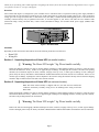
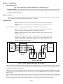
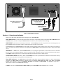
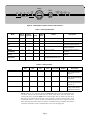
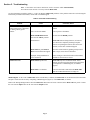
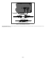
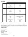
®
w w w.apc.com
Home Appliance & Lighting UPS
HI600SQ
Installation Guide and User’s Manual
990-2884 Copyright © 2005 American Power Conversion. All rights reserved.
APC is a registered trademark of American Power Conversion. All other trademarks are the property of their respective owners.
CONTENTS
Page
Overview
Checklist
Section 1. Unpacking/Inspection of Home UPS (at reseller location)
1
1
1
Section 2. Unpacking/Inspection of Home UPS (at customer location)
1
Section 3. Installation
Home UPS Placement
Location Selection
Battery Connection
Install Home UPS
2
2
2
2
Section 4. Controls and Indicators
Home UPS Controls
AWAY/HOME
TEST/MUTE
Circuit Breaker Switch
Home UPS Indicators
Cold Boot
Section 5. Troubleshooting
Manual Bypass
3
3
3
3
3
3
Preventive Maintenance
6
Specifications
7
Warranty
7
Contact Information
7
5
5
FIGURES
Figure 1.
Figure 2.
Figure 3.
Figure 4.
Figure 5.
APC Home UPS
Typical Home Wiring After Home UPS Installation
Home UPS Connections
Home UPS Front Panel Controls and Indicators
Home UPS Bypass Connection
1
2
3
4
6
TABLES
Table 1.
Table 2.
Table 3.
Table 4.
Home UPS Indicators
Load Indications
Home UPS Troubleshooting
APC Home Appliance & Lighting UPS Technical Specifications
i
4
4
5
7
Thank you for purchasing APC’s Home Appliance & Lighting UPS. Please fill out the enclosed Warranty Registration Card, or register
your purchase on-line at: www.apc.com/support.
Overview
APC’s Home UPS (Figure 1) is designed for years of trouble-free use. The Home UPS is a squarewave back-up power supply intended to
serve house loads. It is rated for 600 VA/360W at 230 Vac, 50-Hz, and operates on a wide range of input voltages (100 - 270V). If the input
voltage goes out of range (less than 100V or more than 270V), the utility is isolated and the UPS supplies power to the load from an
externally connected battery (may be purchased from APC, or from the supplier of your choice). The UPS can serve inductive loads
(fluorescent lamps, ceiling and table fans), resistive loads (incandescent lamps), and switched mode power supply (SMPS) loads
(television).
Figure 1. APC Home UPS
Checklist:
Depending on what the customer has ordered, ensure the following items have been delivered:
•
•
Home UPS
Wiring Kit
Section 1. Unpacking/Inspection of Home UPS (at reseller location)
!
Warning: The Home UPS weighs 7 kg. Please handle carefully.
Inspect the shipping containers for signs of obvious damage. If damage to either shipping container is extensive, notify the carrier
and return the unit to the factory. If there are no apparent signs of damage, carefully open the container, and remove the packing
materials (do not discard). Inspect for dents, scratches, warpage of the top cover, or other signs of damage. If unit is damaged,
please notify the factory and obtain a Return Material Authorization number and return the unit as/if instructed. If there are no
obvious signs of damage, repackage the unit for shipment to the customer using the materials already removed from the shipping
container. Ship or otherwise deliver the unit to the customer location.
Section 2. Unpacking/Inspection of Home UPS (at customer location)
Note: The Home UPS Assembly is shipped with two (one male and one female) IEC
connectors and battery assembly wiring for use in installing home wiring to/from the
Home UPS.
Inspect the shipping containers for signs of obvious damage. If damage to either shipping container is extensive, notify the carrier
and return the unit to the factory. If there are no apparent signs of damage to the shipping container, carefully open the container,
and remove the packing materials (do not discard).
!
Warning: The Home UPS weighs 7 kg. Please handle carefully.
Remove the item from the shipping container and Inspect for: dents, scratches, warpage of the top cover, or other signs of damage.
If unit is damaged, please notify the factory and obtain a Return Material Authorization number and return the unit as/if instructed.
Page 1
Section 3. Installation
Home UPS Placement
Note: Once the unit has been completely installed, it is not desirable to move it.
Location selection - Ensure the area where the unit is to be placed is not in direct sunlight (surfaces may become hot).
Further ensure the unit is placed in a dry area away from sources of liquids, and that the vents on each side have at least 15 cm
(6 inches) of unobstructed clearance.
Battery Connection
Connect the red battery terminal lead (protrudes from the lid) to the positive (+) terminal of the battery and connect the black
battery terminal lead (protrudes from the lid) to the negative (-) terminal.
Install Home UPS
Caution: Installation of the Home UPS must be performed by a licensed and qualified
electrician. Failure to comply may result in equipment damage, and may also void the
Warranty.
Figure 2 shows a typical home wiring scenario after installation of the Home UPS Assembly wiring.
Note: The Home UPS can serve inductive loads (fluo rescent lamps, ceiling and table
fans), resistive loads (incandescent lamps), and SMPS loads (television).
Caution: Connecting the Home UPS to a branch circuit that exceeds 16 amps may result
in equipment damage.
Note: Home wiring to power the desired loads should be routed and connected to a single
branch circuit providing a maximum of 16 amps to the circuit, Wiring must be in
accordance with local electric codes and standards. Connected loads must not exceed 360
watts when the Home UPS is On Battery.
Electricity
Board
Meter
E
E
N
N
L
L
Load
Double-Pole
Switch Lighting
Circuit
Input
Output
Wiring for Home UPS
Figure 2. Typical Home Wiring After Home UPS Installation
Connect one end of the electrical cable from the double-pole switch lighting circuit in accordance with local electric codes and
standards. Connect the other end of the electrical cable to the provided IEC connector, and then to the rear panel Input connector on
the Home UPS Assembly (Figures 2 and 3).
Connect one end of the electrical cable from the load in accordance with local electric codes and standards. Connect the other end of
the electrical cable to the provided IEC connector, and then to the rear panel Output connector on the Home UPS Assembly
(Figures 2 and 3).
Connect the battery wiring harness from the battery to the rear panel input connector of the Home UPS (Figure 3) marked 12V
Battery. Once the home wiring is complete and the batteries are connected to the Home UPS Assembly, turn on power at the
Electricity Board Meter then at the Double-Pole Switch Lighting Circuit. The Home UPS will automatically turn on.
Page 2
12V Battery
INPUT
+Ve
Push to Reset
-Ve
N
L
L
OUTPUT
N
Input : 230V, 5A, 50Hz
Output : 230V, 5A, 50HZ
Battery Wiring Output Harness
(Red and Black Wires)
These connectors are provided
with the Home UPS Assembly
and must be installed
on to the wiring.
From Electricity Board Meter
(through Double-Pole
Switch Lighting Circuit)
To Load
Figure 3. Home UPS Connections
Section 4. Controls and Indicators
Please review this section thoroughly before applying power to the Home UPS.
Home UPS Controls - Controls provided on the Home UPS consist of the holiday mode switch marked AWAY/HOME, and the
Test/Mute switch, as well as a rear panel Push to Reset circuit breaker, and are defined in the following:
AWAY/HOME - (also known as the holiday mode switch) - In the HOME position, this two-position rocker switch (Figure 4) sets
the Home UPS so that it will switch to battery output when there is a utility power outage.
In the AWAY position, the Home UPS goes into standby mode and will not switch to battery power in the event of a power outage.
This is to conserve the batteries. However, in this position, the Home UPS will charge the batteries until a utility power failure
occurs.
TEST/MUTE - In TEST mode, when ON MAINS LED is lit, on pressing this push button, the unit will do self test to determine
the state of the system. During On Battery self test it will also show the load status which can be used to find out the load capacity.
In the MUTE position (push in for 5 seconds), this push button switch silences the low battery buzzer.
Circuit Breaker Switch (Rear Panel) - When in ON MAINS mode, if the system draws more than 10A, circuit breaker will trip.
To reset the circuit breaker switch, push the switch fully inward.
Home UPS Indicators - The Home UPS provides light emitting diode (LED) indicators (Figure 4) to show the operational
condition of the Home UPS and batteries. Indicators consist of Inverter Load Status (25%, 50%, 75%, 100%, and OVER
LOAD). Other indicators consist of: INVERTER DISABLE, ON MAINS, ON BATTERY, and FAULT). Using Table 1,
determine the condition of the Home UPS and battery.
Cold Boot - To turn on the Home UPS on Battery Mode, press the Test-Mute button and hold it for 2-3 seconds.
Page 3
AWAY
25%
50%
75%
100%
TEST
OVER
LOAD
INVERTER LOAD
ON
INVERTER ON
DISABLE MAINS BATTERY FAULT
MUTE
HOME
Figure 4. Home UPS Front Panel Controls and Indicators
Table 1. Home UPS Indicators
On
Mains
(green)
On
Battery
(yellow)
Fault
(red)
INV
Disable
(red)
Buzzer
On
Off
Off
Off
Off
The unit is ON-LINE.
ON LINE SELF TEST
Flashing
Off
Off
Off
Off
The unit is in ON-LINE Self-Test mode.
ON BATTERY SELF
TEST
Flashing
On
Off
Off
Off
The unit is in ON-BATTERY Self-Test
mode, and the load is less than 25%.
ON BATTERY
Off
On
Off
Off
BATTERY
DISCONNECTED
On
Off
Flashing
Off
Chirp every 2 seconds
The unit is ON-LINE mode; battery is
disconnected.
Short Circuit (heavy
overload)
Off
Off
On
Off
Continuously On
The unit is in FAULT state, due to short
circuit fault.
ON BATTERY Low
Battery Warning
Off
On
Off
Off
Constant Beeping, Can be muted through
front panel TEST/MUTE push button.
Mode
ON LINE
Description
The unit is in ON-BATTERY mode, and
the load is less than 25%.
Table 2. Load Indications
25%
50%
75%
100%
Overload
Buzzer
Description
Power Meter
on
off
off
off
off
off
The unit is in ON-BATTERY
mode, and the load is less
than 25%.
Power Meter
on
on
off
off
off
off
The unit is in ON-BATTERY
mode, and the load is between
25% and 50%.
Power Meter
on
on
on
off
off
off
The unit is in ON-BATTERY
mode, and the load is between
50% and 75%.
Power Meter
on
on
on
on
off
off
The unit is in ON BATTERY
mode; the load is between
75% and the overload limit.
NOTE: In the case of a sustained overload, the Home UPS will be turned off automatically after
one minute, and will wait in the fault state for a minute. After that, it will restart again. If the
overload still persists, the Home UPS will be turned off again after one minute, and will wait in
fault state for one minute and restart again. In the same way, it will try for three restarts. If the
overload still persists, it will stay in fault state permanently until the unit is restarted with push
button. If the time interval between two consecutive overloads is more than 5 minutes, then the latest
overload is considered as a fresh overload and three restart cycle will begin again.
Page 4
Section 5. Troubleshooting
Note: If the Home UPS causes interference with a television while ON-BATTERY,
move the television at least 3 feet away from the Home UPS.
Use the information provided in Tables 1, 2, and 3 to diagnose Home UPS problems. If the problem cannot be resolved using the
information provided in this manual, contact APC Technical Support.
Table 3. Home UPS Troubleshooting
Problem
Home UPS fails to operate
when mains power is turned on,
or during a utility power
failure.
Home UPS faults.
Cause
Corrective Action
Disconnected battery.
Ensure batteries are connected as defined in this
manual.
Power is off at the Mains.
Turn on power at the Mains.
Home UPS HOME/AWAY
switch in the AWAY position.
Set switch to the HOME position.
Dead batteries.
Home UPS failed to charge batteries, or batteries
were allowed to completely discharge. Replace
batteries. If replacing the batteries does not fix the
problem, contact APC Technical Support.
Home UPS rear panel Push to
Reset circuit breaker has tripped.
Reset the circuit breaker by pushing it fully inward
until it stops; release the circuit breaker.
Improper wiring installation or
loose connection.
Ensure wiring is as described earlier in this manual,
and that all connections are secure.
Home UPS drops the load.
Home UPS may have an internal failure. If this
happens, the unit can be disconnected from the mains
by completion of a Manual Bypass (see Manual
Bypass).
Home UPS is overloaded.
Turn off some loads connected to the Home UPS
until the OVER LOAD LED is no longer lit
Manual Bypass - In the event of Home UPS failure or dead battery condition, the Home UPS can be disconnected from the mains
and power restored to the circuit by completing a Manual Bypass (Figure 6) of the Home UPS, as follows:
Remove the Wiring Management Kit from the Home UPS. Disconnect all wires connected at the Home UPS rear panel. Connect
the wire from the Input socket to the wire from the Output socket.
Page 5
INPUT
N
L
L
OUTPUT
N
Push to Reset
Input : 230V, 5A, 50Hz
Output : 230V, 5A, 50HZ
Disconnect from
Home UPS
Connect Both Wires
Completed Bypass Connection
Figure 5. Home UPS Bypass Connection
Preventive Maintenance - Preventive maintenance consists of inspecting the batteries for cracks and/or leakage, and checking battery fluid levels and
filling the batteries every 90 days.
Page 6
Specifications
Table 4. APC Home Appliance & Lighting UPS Technical Specifications
Item
Specification
Nominal Voltage
230 V
Rated Voltage
230 V
Frequency
47-53 Hz
Nominal Rated Current
2.61 A
Input Circuit Breaker Rating
10 A
Input Voltage Window for Utility Operation
100 - 270 VAC
Voltage (on Mains)
100 - 270 VAC
Voltage (on battery)
180 - 250 VAC
Rated VA
600 VA
Rated Watts
360 W
Overload Indicated ON BATTERY
>100%
Shutdown due to OVERLOAD
> 100% after 60 seconds (see Table 1 and following note)
Frequency (ON BATTERY)
50 Hz +/- 1%
Surge
Protection
Built-in Surge Protection
Protects the load from surges and spikes
Environmental
Ambient Operating Temperature
0-45 degrees C
Humidity
95% Relative humidity, non-condensing
Altitude
3000 m
Input Line
IEC socket
Outlet Receptacles
IEC socket
Dimensions - Unit (h) x (w) x (d)
UPS: 13.0 x 50.6 x 29.3 cm
Weight
UPS : 7 kg
Shipping Weight
UPS : 8 kg
Input
Characteristics
Output
Characteristics
Physical
Warranty
APC Warrants its products to be free from defects in materials and workmanship under normal use and service for 2 years for the Home
UPS, and 2 years for the Batteries to the original purchaser. Its obligation under this warranty is limited to repairing or replacing, at its sole
option, any such defective products. To obtain service under warranty you must obtain a Return Material Authorization (RMA) number
from APC Technical Support or an APC Service Center. The defective unit must be returned with an RMA number, with transportation
charges prepaid and it must be accompanied by a brief description of the problem and proof of date and place of purchase. This warranty
applies only to the original purchaser.
Contact Information
APC Corporate Office
132 Fairgrounds Road
West Kingston, RI 02892, USA
Tel: 401-789-0204
APC Corporate Office (India)
27 Lavelle Road, Bangalore 560 001
www.apc.com
Toll Free Helpline: 1600 444 272 and 1600 444 877
email: [email protected]
Technical Webchat: www.apc.com/in
Page 7