1
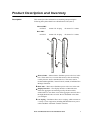
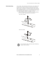
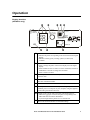
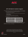
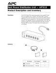
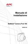
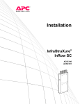
Basic and Metered Rack
Power Distribution Unit
AP7862J
AP7562J
Installation and
Quick-Start Manual
This manual is available in English on the enclosed CD.
Contents
Product Description and Inventory . . . . . . . . . . . . . . . . . . . . . . 1
Description . . . . . . . . . . . . . . . . . . . . . . . . . . . . . . . . . . . . . . . . 1
Additional documentation . . . . . . . . . . . . . . . . . . . . . . . . . . . . . 2
Inventory . . . . . . . . . . . . . . . . . . . . . . . . . . . . . . . . . . . . . . . . . 2
Receiving inspection . . . . . . . . . . . . . . . . . . . . . . . . . . . . . . . . . 2
Please recycle . . . . . . . . . . . . . . . . . . . . . . . . . . . . . . . . . . . . . . 2
InfraStruXure certified . . . . . . . . . . . . . . . . . . . . . . . . . . . . . . . . 2
How to Install the Basic and Metered PDU. . . . . . . . . . . . . . . . . 3
Attach the cord retention trays . . . . . . . . . . . . . . . . . . . . . . . . . 3
Attach cords to the tray . . . . . . . . . . . . . . . . . . . . . . . . . . . . . . 3
Mounting options . . . . . . . . . . . . . . . . . . . . . . . . . . . . . . . . . . . 3
Toolless mounting . . . . . . . . . . . . . . . . . . . . . . . . . . . . . . . . . . . 4
Bracket-mounting . . . . . . . . . . . . . . . . . . . . . . . . . . . . . . . . . . . 5
Operation . . . . . . . . . . . . . . . . . . . . . . . . . . . . . . . . . . . . . . . . . 7
Quick Configuration for a Metered PDU. . . . . . . . . . . . . . . . . . . 8
Overview . . . . . . . . . . . . . . . . . . . . . . . . . . . . . . . . . . . . . . . . . 8
TCP/IP configuration methods . . . . . . . . . . . . . . . . . . . . . . . . . . 8
APC Management Card Wizard . . . . . . . . . . . . . . . . . . . . . . . . . 8
BOOTP & DHCP configuration . . . . . . . . . . . . . . . . . . . . . . . . . . 9
Local access to the control console . . . . . . . . . . . . . . . . . . . . . 11
Remote access to the control console . . . . . . . . . . . . . . . . . . . 11
Control console . . . . . . . . . . . . . . . . . . . . . . . . . . . . . . . . . . . . 12
How to Access a Configured PDU . . . . . . . . . . . . . . . . . . . . . . 13
Overview . . . . . . . . . . . . . . . . . . . . . . . . . . . . . . . . . . . . . . . . 13
Browser interface . . . . . . . . . . . . . . . . . . . . . . . . . . . . . . . . . . 13
Telnet . . . . . . . . . . . . . . . . . . . . . . . . . . . . . . . . . . . . . . . . . . . 13
SNMP . . . . . . . . . . . . . . . . . . . . . . . . . . . . . . . . . . . . . 13
FTP . . . . . . . . . . . . . . . . . . . . . . . . . . . . . . . . . . . . . . 13
How to Recover From a Lost Password . . . . . . . . . . . . . . . . . . 14
Specifications . . . . . . . . . . . . . . . . . . . . . . . . . . . . . . . . . . . . . 15
Basic and Metered Rack Power Distribution Unit
i
Warranty and Service . . . . . . . . . . . . . . . . . . . . . . . . . . . . . . . 16
Limited warranty . . . . . . . . . . . . . . . . . . . . . . . . . . . . . . . . . . . 16
Warranty limitations . . . . . . . . . . . . . . . . . . . . . . . . . . . . . . . . 16
Obtaining service . . . . . . . . . . . . . . . . . . . . . . . . . . . . . . . . . . 16
Life-Support Policy . . . . . . . . . . . . . . . . . . . . . . . . . . . . . . . . . . 17
General policy . . . . . . . . . . . . . . . . . . . . . . . . . . . . . . . . . . . . . 17
Examples of life-support devices . . . . . . . . . . . . . . . . . . . . . . . 17
ii
Basic and Metered Rack Power Distribution Unit
Product Description and Inventory
Description
This manual provides information on installing and operating the
following three-phase Rack Power Distribution Units (PDUs):
Metered PDU
AP7862J:
NEMA L21-20 plug
42 NEMA 5-15 outlets
NEMA L21-20 plug
42 NEMA 5-15 outlets
Basic PDU
AP7562J:
Metered PDU —Metered PDUs distribute power to devices in the
rack. These PDUs have a sensor that measures the current being
used by the PDU and it’s attached devices. The sensor can be
monitored through Web, Control Console, SNMP, or InfraStruXure
Manager interfaces.
Basic PDU —Basic PDUs distribute power to devices in the rack.
Display Interface—The display interface on Metered PDUs
shows the aggregate current being used by the PDU and its
attached devices. An alarm occurs if the aggregate current is above
the high threshold value or below the low threshold values that
you configure.
L21-20 plug—Both PDUs have
an L21-20 plug, which connects to
a variety of APC equipment, including InfraStruXure PDU power
cables and Rack Automatic Transfer Switches.
Basic and Metered Rack Power Distribution Unit
1
Product Description and Inventory
Additional
documentation
The Metered Rack PDU User’s Guide and the Metered Rack PDU
Addendum are available on the supplied CD or on our Web site:
http://www.apc.com/.
The online user’s guide (.\Doc\eng\usrguide.pdf) contains additional
information about the following topics related to the PDU:
• Management interfaces
• User accounts
• Customizing setup
• Security
The addendum (.\Doc\eng\addendum.pdf) contains additional
information about the following topics:
• The Wizard
• Configuration utilities
• File transfers
Inventory
Receiving inspection
Please recycle
Quantity
Item
1
Configuration cable (940-0144) included
with the AP7862J only
3
Cord retention tray (with 12 flat-head screws
and 42 wire ties)
1
APC Basic and Metered Power Distribution
Units Utility CD
1
Warranty registration card
Inspect the package and contents for shipping damage, and make sure
that all parts were sent. Report any damage immediately to the shipping
agent, and report missing contents, damage, or other problems
immediately to APC or your APC reseller.
The shipping materials are recyclable. Please save them for
later use, or dispose of them appropriately.
InfraStruXure certified
This product is certified for use in InfraStruXure systems. See the
InfraStruXure Manager’s configuration instructions included with your
system.
2
Basic and Metered Rack Power Distribution Unit
How to Install the Basic and Metered PDU
Attach the cord
retention trays
Attach the cord retention trays to the PDU, using four flat-head screws
(provided) per tray.
Attach cords to the tray
Attach a cord to the tray by looping the cord and securing it to the tray,
using a wire tie (provided).
Each cord must be secured to the tray so that you can
unplug it from the PDU without removing the wire tie.
Note
Mounting options
Install the PDU in the rear of the NetShelter VX Enclosure, in the cable
channel directly behind the rear vertical mounting rails. You can install
the PDU in one of two ways: using toolless mounting pegs (provided) or
the mounting brackets (sold separately).
You can order a rack-mount bracket kit from APC
(AR8116BLK).
Note
Basic and Metered Rack Power Distribution Unit
3
How to Install the Basic and Metered PDU
Toolless mounting
1. Slide the mounting pegs into the holes located in the channel in the
rear panel of the enclosure.
2. Snap the PDU into place by pushing it downward until it locks into
position.
You can mount two PDUs on one side of the enclosure by
using the toolless mounting method.
Note
4
Basic and Metered Rack Power Distribution Unit
How to Install the Basic and Metered PDU
Bracket-mounting
You can order a rack-mount bracket kit from APC (AR8116BLK). The
brackets attach to the PDU in either of two directions, shown in the
figures in step 1. Consider the orientation of the PDU in the enclosure
before attaching the brackets. A recessed orientation allows the PDU to
be mounted flush with the enclosure; a raised orientation allows you to
route cables through the channel (see the figures in step 2).
1. Attach two brackets to the rear of the PDU, using two pan-head
screws (provided in the bracket kit) for each bracket.
– Recessed orientation
– Raised orientation
You can mount two PDUs on one side of the enclosure by
using the raised orientation.
Note
Basic and Metered Rack Power Distribution Unit
5
How to Install the Basic and Metered PDU
2. Insert mounting screws (provided with the bracket kit) in the top
and bottom positions in the channel where the brackets align with
the holes. Tighten the screws to secure the PDU to the enclosure.
– Recessed orientation
– Raised orientation
6
Basic and Metered Rack Power Distribution Unit
Operation
Display interface
(AP7862J only)
- OK
- Warning
- Overload
L1
L2
Press to
select line.
Press and hold
to invert display.
L3
Link - Rx/Tx
10 /100
Amps
Amps
Status
Reset
Serial Port
Phase Indicator LEDs:
• Indicates the phase corresponding to the current listed in the digital
display.
• Indicates normal (green), warning (yellow) or alarm (red)
condition.
Control button:
• Press to change the phase of the current displayed on the digital
display.
• Press and hold for five seconds to view the orientation; hold for an
additional five seconds to change the orientation.
• Press to silence an alarm.
Ethernet port: Connects the PDU to your network, using a CAT5
network cable.
Status LED: Indicates the status of the ethernet LAN connection and
the state of the Metered PDU.
Link LED: Indicates whether there is activity on the network.
Serial port: Access internal menus by connecting this port (RJ-11
modular port) to a serial port on your computer, using the supplied
serial cable (part number 940-0144).
Display of the current used by the PDU and attached devices:
• Shows the aggregate current for the phase corresponding to the
Phase Indicator LED that is illuminated.
• Cycles through all three phases in 3-second intervals.
Reset switch: Resets the PDU to its default settings.
Basic and Metered Rack Power Distribution Unit
7
Quick Configuration for a Metered PDU
Warning
Overview
You must configure the following TCP/IP settings before the PDU can
operate on a network:
• IP address of the PDU
• Subnet mask
• Default gateway
Note
TCP/IP configuration
methods
APC Management Card
Wizard
Disregard the procedures in this section if you have APC
InfraStruXure Manager as part of your system. See the
InfraStruXure Manager’s documentation for more
information.
If a default gateway is unavailable, use the IP address of a
computer that is located on the same subnet as the PDU and
that is usually running. The PDU uses the default gateway to
test the network when traffic is very light. See “Watchdog
Features” in the “Introduction” of the user’s guide for more
information about the watchdog role of the default gateway.
Use one of the following to define the TCP/IP settings:
• APC Management Card Wizard (See “APC Management Card
Wizard” on page 9.)
• BOOTP or DHCP server (See “BOOTP & DHCP configuration” on
page 10.)
• Local computer (See “Local access to the control console” on
page 11.)
• Networked computer (See “Remote access to the control console”
on page 11.)
You can use the APC Management Card Wizard at a Windows® 98,
Windows NT® 4.0, Windows 2000, or Windows XP computer to
configure a PDU.
1. Insert the Utility CD into a computer on your network.
2. Launch the Wizard, when you are prompted, or, if you are
prompted to restart the computer, access the Wizard from the Start
menu after the computer has restarted.
3. Wait for the Wizard to discover the unconfigured PDU, and then
follow the on-screen instructions.
Note
8
If you leave the Start a Web browser when finished
option enabled, you can use apc for both the User Name
and Password to access the PDU through your browser.
Basic and Metered Rack Power Distribution Unit
Quick Configuration for a Metered PDU
BOOTP & DHCP
configuration
The Boot Mode setting, a TCP/IP option in the PDU’s Network menu,
identifies how TCP/IP settings will be defined. The possible settings are
Manual, DHCP only, BOOTP only, and DHCP & BOOTP (the default
setting).
Note
The DHCP & BOOTP setting assumes that a properly
configured DHCP or BOOTP server is available to provide
TCP/IP settings to the APC PDUs. If these servers are
unavailable, see “APC Management Card Wizard” on
page 9, “Local access to the control console” on page 11, or
“Remote access to the control console” on page 11 to
configure the TCP/IP settings.
With Boot Mode set to DHCP & BOOTP, the PDU attempts to discover a
properly configured server. It first searches for a BOOTP server, and then a
DHCP server. It repeats this pattern until it discovers a BOOTP or DHCP
server.
For more information, see “BOOTP” on this page or
“DHCP” on page 10.
BOOTP. You can use an RFC951-compliant BOOTP server to configure the
TCP/IP settings for the PDU. If the BOOTP server is properly configured,
the PDU’s default setting (DHCP & BOOTP) for BOOT Mode causes it to
discover the BOOTP server.
If a BOOTP server is unavailable, see “APC Management
Card Wizard” on page 9, “Local access to the control
console” on page 11, or “Remote access to the control
console” on page 11 to configure TCP/IP settings.
1. Enter the PDU’s MAC and IP addresses, the subnet mask and default
gateway settings, and an optional bootup file name in the BOOTPTAB
file of the BOOTP server.
For the MAC address, look on the bottom of the PDU or on
the Quality Assurance slip included in the package.
Note
2. When the PDU reboots, the BOOTP server provides it with the TCP/IP
settings.
– If you specified a bootup file name, the PDU attempts to transfer
that file from the BOOTP server using TFTP or FTP. The PDU
assumes all settings specified in the bootup file.
– If you did not specify a bootup file name, the PDU can be
configured remotely by using Telnet or by using the Web interface:
User Name and Password are both apc, by default.
See “Remote access to the control console” on page 11 for
configuration instruction.
Basic and Metered Rack Power Distribution Unit
9
Quick Configuration for a Metered PDU
See also
You must use the APC Management Card Wizard to create
the bootup file. To create a bootup file, see the BOOTP
section in the addendum.
DHCP. You can use a RFC2131/RFC2132-compliant DHCP server to
configure the TCP/IP settings for the PDU.
See also
This section briefly summarizes the PDU communication
with a DHCP server. For more detail about how a DHCP
server is used to configure the network settings for the PDU,
see “DHCP Configuration” in the User’s Guide.
1. The PDU sends a DHCP request that uses the following to identify
itself:
– Vendor Class Identifier (APC by default)
– Client Identifier (by default, the PDU’s MAC address value)
– User Class Identifier (by default, the identification of the PDU’s
application firmware)
2. A properly configured DHCP server responds with a DHCP offer
that includes all of the settings that the PDU needs for network
communication. The DHCP offer also includes the Vendor Specific
Information option (DHCP option 43). By default, the PDU ignores
DHCP offers that do not encapsulate the APC cookie in the Vendor
Specific Information option using the following hexidecimal
format:
Option 43 = 01 04 31 41 50 43
where
– The first byte (01) is the code
– The second byte (04) is the length
– The remaining bytes (31 41 50 43) are the APC cookie
See your DHCP server documentation to add code to the
Vendor Specific Information option.
See also
To disable the APC cookie requirement, see “Local access
to the control console” on page 11. To change the control
console’s DHCP Cookie Is setting, an Advanced option in
the TCP/IP menu, see “Remote access to the control
console” on page 11.
10
Basic and Metered Rack Power Distribution Unit
Quick Configuration for a Metered PDU
Local access to the
control console
You can use a local computer to connect to the PDU to access the control
console.
1. Select a serial port at the local computer, and disable any service
which uses that port.
2. Use the configuration cable (940-0144) to connect the selected port
to the serial port on the front panel of the PDU.
3. Run a terminal program (such as HyperTerminal) and configure
the selected port for 9600 bps, 8 data bits, no parity, 1 stop bit, and
no flow control, and save the changes.
4. Press ENTER to display the User Name prompt.
5. Use apc for the user name and password.
6. See “Control console” on page 13 to finish the configuration.
Remote access to the
control console
From any computer on the same subnet as the PDU, you can use ARP
and Ping to assign an IP address to the PDU, and then use Telnet to
access that PDU’s control console and configure the needed TCP/IP
settings.
Note
After the PDU has its IP address configured, you can use
Telnet, without first using ARP and Ping, to access that
PDU.
1. Use ARP to define an IP address for the PDU, and use the PDU’s
MAC address in the ARP command. For example, to define an IP
address of 156.205.14.141 for the PDU that has a MAC address of 00
c0 b7 63 9f 67, use one of the following commands:
– Windows command format:
arp -s 156.205.14.141 00-c0-b7-63-9f-67
– LINUX command format:
arp -s 156.205.14.141 00:c0:b7:63:9f:67
For the MAC address, look on the bottom of the PDU or on
the Quality Assurance slip included in the package.
Note
2. Use Ping with a size of 113 bytes to assign the IP address defined
by the ARP command. For example:
– Windows command format:
ping 156.205.14.141 -l 113
– LINUX command format:
ping 156.205.14.141 -s 113
Basic and Metered Rack Power Distribution Unit
11
Quick Configuration for a Metered PDU
3. Use Telnet to access the PDU at its newly assigned IP address. For
example:
telnet 156.205.14.141
4. Use apc for both User Name and Password.
5. See “Control console” on this page to finish the configuration.
Control console
After you log on at the control console, as described in “Local access to
the control console” on page 11 or “Remote access to the control
console” on page 11:
1. Choose Network from the Control Console menu.
2. Choose TCP/IP from the Network menu.
3. If you are not using a BOOTP or DHCP server to configure the
TCP/IP settings, select the Boot Mode menu. Select Manual boot
mode, and then press ESC to return to the TCP/IP menu. (Changes
will take effect when you log out.)
4. Set the System IP, Subnet Mask, and Default Gateway address
values.
5. Press CTRL-C to exit to the Control Console menu.
6. Log out (option 4 in the Control Console menu).
Note
12
If you disconnected a cable during the procedure
described in “Local access to the control console” on
page 11, reconnect that cable and restart the associated
service.
Basic and Metered Rack Power Distribution Unit
How to Access a Configured PDU
Overview
After the PDU is running on your network, you can use several different
interfaces to access the PDU.
To use the interfaces identified here, see the user’s guide
and the addendum.
Note
Browser interface
As your browser, use Microsoft® Internet Explorer 5.5 (or higher) to
configure PDU options or to view the Event log.
1. Address the PDU by its IP address, or by its DNS name (if a DNS
name is configured).
2. Enter the User Name and Password (apc by default).
Telnet
You can use Telnet to access a PDU’s control console from any computer
on the same subnet.
1. At a command prompt, use the following command line, and press
ENTER:
telnet address
As address, use the PDU’s IP address or its DNS name (if a DNS
name is configured).
2. Enter the User Name and Password (apc by default).
SNMP
After you add the PowerNet MIB to a standard SNMP MIB browser, you
can use that browser for SNMP access to the PDU. The default read
community name is public; the default read/write community name is
private.
FTP
You can use FTP (enabled by default) to download new firmware to the
PDU, or to access a copy of the PDU’s event log.
1. At a command prompt, use the following command line, and press
ENTER:
ftp address
As address, use the PDU’s IP address.
2. Enter the User Name and Password (apc by default).
Basic and Metered Rack Power Distribution Unit
13
How to Recover From a Lost Password
You can use a local computer that connects to the PDU through the serial
port on the front panel of the unit.
1. Select a serial port at a local computer, and disable any service that
uses the port.
2. Use the configuration cable (940-0144) to connect the selected port
to the serial port on the front panel of the PDU.
3. Run a terminal program (such as HyperTerminal) and configure
the selected port for 9600 bps, 8 data bits, no parity, 1 stop bit, and
no flow control, and save the changes.
4. Press ENTER to display the User Name prompt.
5. Press the Reset button on the PDU, which causes the PDU to restart,
a process that typically takes approximately 15 seconds.
6. Press ENTER as many times as necessary to redisplay the User
Name prompt, then use apc for the User Name and Password. (If
you take longer than 30 seconds to log on after the User Name
prompt is redisplayed, you must start the login procedure again at
step 4.)
7. From the Control Console menu, select System, then User
Manager.
8. Select Administrator, and change the User Name and Password
settings, both of which are now defined as apc.
9. Press CTRL-C and log off.
Reconnect any cable that you disconnected in step 2 and
restart any service that you disabled in step 1.
Note
14
Basic and Metered Rack Power Distribution Unit
Specifications
AP7862J/AP7562J
Electrical
Nominal input voltage
173 V, 3-phase
Acceptable input voltage
± 10% Nominal input voltage
Input frequency
47–63 Hz
Input connectors
NEMA L21-20 plug
Output connectors
42 NEMA 5-15 outlets
Maximum total current draw
20 A per Phase
Physical
Size (H × W × D)
70.00 ×2.19×1.73 in
(177.80 ×5.56×4.39 cm)
Weight
5.44 kg
Shipping weight
6.35 kg
Environmental
Elevation (above MSL)
Operating
Storage
0–15,000 ft (0–4500 m)
0–50,000 ft (0–15 000 m)
Temperature
Operating
Storage
0 to 45° C (32 to 115° F)
–25 to 65° C (–13 to 149° F)
Humidity
Operating
Storage
5–95% RH Non-condensing
5–95% RH Non-condensing
Approvals
EMC verification
VCCI Class A (for AP7862J only)
Safety verification
METI DENAN
Basic and Metered Rack Power Distribution Unit
15
Warranty and Service
Limited warranty
APC warrants the PDU to be free from defects in materials and
workmanship for a period of two years from the date of purchase. Its
obligation under this warranty is limited to repairing or replacing, at its
own sole option, any such defective products. This warranty does not
apply to equipment that has been damaged by accident, negligence, or
misapplication or has been altered or modified in any way. This
warranty applies only to the original purchaser.
Warranty limitations
Except as provided herein, APC makes no warranties, express or
implied, including warranties of merchantability and fitness for a
particular purpose. Some jurisdictions do not permit limitation or
exclusion of implied warranties; therefore, the aforesaid limitation(s) or
exclusion(s) may not apply to the purchaser.
Except as provided above, in no event will APC be liable for direct,
indirect, special, incidental, or consequential damages arising out of
the use of this product, even if advised of the possibility of such
damage.
Specifically, APC is not liable for any costs, such as lost profits or
revenue, loss of equipment, loss of use of equipment, loss of software,
loss of data, costs of substitutes, claims by third parties, or otherwise.
This warranty gives you specific legal rights and you may also have
other rights, which vary according to jurisdiction.
Obtaining service
To obtain support for problems with your PDU:
0
1. Note the serial number and date of purchase. The serial number is
located on the bottom of the PDU.
2. Contact Customer Support at a phone number located on the back
cover. A technician will try to help you solve the problem by
phone.
3. If you must return the product, the technician will give you a return
material authorization (RMA) number. If the warranty expired, you
will be charged for repair or replacement.
4. Pack the unit carefully. The warranty does not cover damage
sustained in transit. Enclose a letter with your name, address, RMA
number and daytime phone number; a copy of the sales receipt;
and a check as payment, if applicable.
5. Mark the RMA number clearly on the outside of the shipping
carton.
6. Ship by insured, prepaid carrier to the address provided by the
Customer Support technician.
16
Basic and Metered Rack Power Distribution Unit
Life-Support Policy
General policy
American Power Conversion (APC) does not recommend the use of any
of its products in the following situations:
• In life-support applications where failure or malfunction of the
APC product can be reasonably expected to cause failure of the
life-support device or to affect significantly its safety or
effectiveness.
• In direct patient care.
APC will not knowingly sell its products for use in such applications
unless it receives in writing assurances satisfactory to APC that (a) the
risks of injury or damage have been minimized, (b) the customer
assumes all such risks, and (c) the liability of American Power
Conversion is adequately protected under the circumstances.
a
Examples of life-support
devices
The term life-support device includes but is not limited to neonatal
oxygen analyzers, nerve stimulators (whether used for anesthesia, pain
relief, or other purposes), autotransfusion devices, blood pumps,
defibrillators, arrhythmia detectors and alarms, pacemakers,
hemodialysis systems, peritoneal dialysis systems, neonatal ventilator
incubators, ventilators (for adults and infants), anesthesia ventilators,
infusion pumps, and any other devices designated as “critical” by the
U.S. FDA.
Hospital-grade wiring devices and leakage current protection may be
ordered as options on many APC UPS systems. APC does not claim that
units with these modifications are certified or listed as hospital-grade by
APC or any other organization. Therefore these units do not meet the
requirements for use in direct patient care.
Basic and Metered Rack Power Distribution Unit
17
Radio Frequency Interference
Warning
Changes or modifications to this unit not
expressly approved by the party
responsible for compliance could void the
user’s authority to operate this
equipment.
This equipment has been tested and found to comply with the limits for a
Class A digital device, pursuant to part 15 of the FCC Rules. These limits
are designed to provide reasonable protection against harmful interference
when the equipment is operated in a commercial environment. This
equipment generates, uses, and can radiate radio frequency energy and, if
not installed and used in accordance with this user manual, may cause
harmful interference to radio communications. Operation of this
equipment in a residential area is likely to cause harmful interference. The
user will bear sole responsibility for correcting such interference.
This Class A digital apparatus complies with Canadian ICES-003.
Cet appareil numérique de la classe A est conforme à la norme NMB-003
du Canada.
a
警告使用者:
這是甲類的資訊産品, 在居住的
環境中使用時,可能會造成射頻
干擾,在這種情況下,使用者會
被要求採取某些適當的對策。
この装置は規定に準拠しています。
この装置を住宅地域またはその周
囲で使用する場合、 ラジオやテレビヘの
電波障害を及ぼすことがあリます。 VCCI-A
APC Worldwide Customer Support
Customer support for this or any other APC product is available at no charge in any of the following ways:
• Visit the APC Web site to find answers to frequently asked questions (FAQs), to access documents
in the APC Knowledge Base, and to submit customer support requests.
– www.apc.com (Corporate Headquarters)
Connect to localized APC Web sites for specific countries, each of which provides customer
support information.
– www.apc.com/support/
Global support with FAQs, knowledge base, and e-support.
• Contact an APC Customer Support center by telephone or e-mail.
– Regional centers:
Direct InfraStruXure Customer Support Line
(1)(877)537-0607 (toll free)
APC headquarters U.S., Canada
(1)(800)800-4272 (toll free)
Latin America
(1)(401)789-5735 (USA)
Europe, Middle East, Africa
(353)(91)702020 (Ireland)
Japan
(0) 35434-2021
– Local, country-specific centers: go to www.apc.com/support/contact for contact information.
Contact the APC representative or other distributor from whom you purchased your APC product for
information on how to obtain local customer support.
Entire contents copyright © 2003 American Power Conversion. All rights reserved.
Reproduction in whole or in part without permission is prohibited. APC, the APC logo,
InfraStruXure, and NetShelter are trademarks of American Power Conversion Corporation
and may be registered in some jurisdictions. All other trademarks, product names, and
corporate names are the property of their respective owners and are used for informational
purposes only.
990-1414A
06/2003