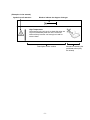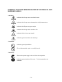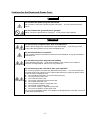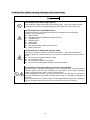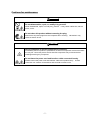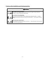
1
N8141-42F Disk Expansion Unit User's Guide 855-900725-901- A Thank you very much for purchasing the N8141-42F Disk Expansion Unit. This is a guide to the safe and proper use of the N8141-42F Disk Expansion Unit (hereafter, Disk Expansion Unit). Be sure to read this guide before handling this Disk Expansion Unit. Please refer to this guide if there is something that you do not understand or a problem occurs while using this Disk Expansion Unit. Store this guide close to this Disk Expansion Unit for easy reference. Keep this operation manual on hand so that you can refer to it when necessary. Be sure to read the "Safety Precautions" and "Precautions on Use." Notes on USE - Always read the notes.The following includes information necessary for proper and safe operation of the Disk Expansion Unit. SAFETY INDICATIONS To ensure proper and safe use of the Disk Expansion Unit, handle the Disk Expansion Unit depending on the direction of the User’s Guide. The User’s Guide describes possible dangers in use of the Disk Expansion Unit, the dangers you encounter if you do not observe the instructions, and the ways to avoid the dangers. Warning labels are attached to components with possible danger or their vicinity in the Disk Expansion Unit when operating the Disk Expansion Unit. In the User’s Guide and the warning labels, "WARNING" and "CAUTION" are used as the terms indicating hazardous levels. The terms are defined to have the following meanings. WARNING CAUTION Indicates the presence of a hazard that may result in death or serious personal injury. Indicates the presence of a hazard that may cause minor personal injury, including burns, or property damage. Precautions and notices against hazards are presented with one of the following three symbols. The individual symbols are defined as follows: This symbol indicates the presence of a hazard. An image in the symbol illustrates the hazard type. (Attention) This symbol indicates prohibited actions. An image in the symbol illustrates a particular prohibited action. (Prohibited Action) This symbol indicates mandatory actions. An image in the symbol illustrates a mandatory action to avoid a particular hazard. (Mandatory Action) -1- (Examples in the manual) Symbol to call attention Word to indicate the degree of danger CAUTION High Temperature Components in the unit such as hard disk drive are very hot immediately after the unit is turned off. Wait until they become cool enough to install or remove them. Description of the caution -2- Illustration indicating the prohibited action (may be omitted) SYMBOLS AND THEIR MEANINGS USED IN THIS MANUAL AND WARNING LABELS - Attention: Indicates that it may cause an electric shock. Indicates that it may cause damage due to high temperature. Indicates that fingers may get caught. Indicates that it may cause smoke or fire. Indicates that hair may get caught. Indicates general cautions and warnings. - Prohibited: Indicates general prohibition. Do not disassemble, repair, or modify the unit. - Mandatory: Remove the power plug of this unit from the receptacle. Indicates general actions of the user. indicated. -3- Perform operations as SAFETY INSTRUCTIONS Read the cautions described here to use this product safely. For information on the symbols, refer to “Safety Symbols” at the beginning of this manual. General Cautions WARNING Do not use this product for services involving human lives or requiring high reliability. This product is not intended to be used with or control facilities or devices concerning human lives, including medical devices, nuclear facilities and devices, aeronautics and space devices, transportation facilities and devices; and facilities and devices requiring high reliability. NEC assumes no liability for any accident resulting in personal injury, death, or property damage if this product has been used in the above conditions. Do not use this product if any smoke, odor, or noise is present. If smoke, odor, or noise is present, immediately turn off the POWER switch and disconnect the all power plugs from the outlet, then contact your sales agent. Using this product in such conditions may cause a fire. Do not insert a wire or metal piece. Do not insert a wire or metal piece into the air vents or opening of the hard disk drive. It may cause an electric shock. CAUTION Do not put water or foreign objects into the product. Do not put any liquid such as water or foreign objects such as metal pieces into the product. It may cause an electric shock, fire, or failure. If such liquid or objects are taken in the product, turn off the power and remove the all power plugs from the receptacle. -4- Cautions for the Power and Power Cord WARNING Do not hold the power plug with wet hands. Do not insert or remove the power plug with wet hands. You may receive an electric shock. Do not connect the ground line to a gas pipe. Never connect the ground line to a gas pipe. It may cause a gas explosion. CAUTION Do not use any receptacle other than ones specified. Use the power supply from a outlet with the specified voltage. If you use any power supply other than specified, it may cause a leakage or fire. Do not use star-burst connection. If any current more than the rated current flows in the receptacle, it may get overheated and cause fire. Do not leave the power plug inserted halfway. Insert the power plug fully. If you leave it halfway, it may result in poor contact or intrusion of foreign objects, which in turn may cause fire. Do not use any power cord other than ones specified. Do not use any power cord other than attached to this product. Any current more than the rated current may cause fire. Also, observe the following to prevent an electric shock or fire caused by a damaged cord. z Do not hold the cord when you remove the power plug. z Do not pinch the power cord. z Do not fold the power cord. z Do not pour chemicals over the power cord. z Do not twist the power cord. z Do not place any object on the power cord. z Do not bind up the power cord. z Do not alter, modify, or repair the power cord. z Do not use a stapler to fix the power cord. Do not use any damaged power cord. (Replace a damaged power cord with a new one of the same specifications.) -5- Cautions for setup, moving, storage, and connecting WARNING Do not try to lift it with a single person. The maximum weight of this product can be about 32kg. When you need to move it, follow the instructions on the label attached on the product and exercise with care. Do not install it in an unsuitable place. Install this product in such a place as specified in this guide. Avoid the following locations. It may cause a fire. z Direct sunlight. z The space where temperature changes frequently. z Unstable space. z Vibrating space. z Dusty space. z Humid space. z The location where objects are likely to fall. z Nearby chemicals. Do not use any unauthorized interface cable. Use only the interface cable that comes with this product. Use of an unauthorized interface cable may cause a short circuit or a fire. Also, observe the following to prevent a fire. z Do not use any damaged interface cable. z Do not step the cable. z Do not place any object on the cable. z Do not use the cable without interface connecter not fixed. Do not use or store this product in corrosive environment. Avoid the usage or storage of this product in an environment which may be exposed to corrosive gases, such as those including but not limited to: sulfur dioxide, hydrogen sulfide, nitrogen dioxide, chlorine, ammonia and/or ozone. Avoid installing this product in a dusty environment or one that may be exposed to corrosive materials such as sodium chloride and/or sulfur, or conductive metal particles in the air. Such environments may cause corrosion on the printed board in this product, resulting in not only damage to this product, but may even lead to a smoke or fire hazard. -6- Cautions for maintenance WARNING Do not disassemble, repair, or modify it by yourself. Never disassemble, repair, or modify it by yourself. It may cause malfunction, electric shock, or fire. Do not clean this product without removing the plug. Remove the all power plugs from the receptacle when cleaning. Otherwise it may cause an electric shock. CAUTION Avoid installation in extreme temperature conditions. Immediately after this product is powered off, its internal components such as hard disks are very hot. Leave this product until its internal components fully cool down before installing/removing any component. Do not leave the power cord and interface cable connected loosely. Please connect the power cord and interface cable to this product firmly. A loose connection can cause a contact failure and can lead to smoke or fire. -7- Cautions after installation and during operation CAUTION Be careful not to get caught. When this unit is operating, be careful not to insert your finger into the cooling fan opening. Keep your hair from getting caught. Do not touch it at thundering. Remove the all power plugs from the receptacle when thundering starts. If it starts before you remove the power plug, do not touch this product. It may cause an electric shock. Keep your pets away from it. Keep animals such as your pets away from the unit. Their excrement or hair may enter the unit, which may cause fire. -8- Cautions in mounting the product on a rack WARNING Do not install it on a nonconforming rack Do not use this product without a rack or install it on a nonconforming rack. It may not function properly, and there is a risk of damage to physical assets or injuries. For suitable racks, contact your sales agent. Do not use it in an unsuitable place. Do not install the rack on which you install this product in an unsuitable place. Systems may be affected, and the rack may fall over to cause a fire or injuries. For details about installation environment, see the manual attached to the rack or contact your sales agent. CAUTION Do not try to carry or install the rack with a single person Two or more people are required to carry or install the rack. The caster may be in unstable status when it is moved by a single person. Moving it by a single person may cause injury or damage of the unit. Do not concentrate weight. Install a stabilizer or use two or more racks connected together to distribute weight so that weights of the rack and the installed devices will not be concentrated at one point. You can keep the unit stable with earthquake-proof fixtures. Do not install the rack door with a single person. Two or more people are required to install the rack front and rear doors. Otherwise it may cause injury or damage of the rack. Do not insert hinges halfway. When installing the rack door, make sure that hinge pins at top and bottom of the door are completely inserted into the rack.. Failure to follow this instruction may cause the door to fall to be broken and/or to result in personal injury Do not pull it out without securing the rack. When you pull out the unit from the rack, always keep the rack stable by using a stabilizer or earthquake-proof fixtures. Pulling out multiple units at one time may cause the rack to topple over. Always pull out the units one by one. Keep your fingers from getting caught. Be careful and keep your fingers from getting caught when you mount the unit on the rack. -9- WARNING LABELS Warning labels are attached on or around any dangerous parts of this Disk Expansion Unit. These labels are intended to call your attention to any possible danger you may encounter when operating this Disk Expansion Unit. Do not remove the warning labels or make them dirty. If no warning labels are attached, any labels are about to come off or illegible due to stain, contact your dealer. - 10 - 落下注意 注意 CAUTION - 11 - これ以上引くと落下します。 Firmly hold the bottom of the system when removing from the rack cabinet. NOTE ON HANDLING ∼ FOR PROPER OPERATION∼ Observe the following notes for successful operation of the Disk Expansion Unit. Use of the Disk Expansion Unit ignoring the notes will cause malfunctions or failures of the chassis. Make sure to power off the Disk Expansion Unit before connecting or disconnecting the SAS cable between the Unit and the server. Turn off the cellular phone or pager. Radio interference may cause malfunctions of this disk expansion unit. Verify that the HDD LED on the Disk Expansion Unit is not blink before turning off the chassis. When you have just turned off the Disk Expansion Unit, wait at least 30 seconds before turning it back on. Turn off the power and unplug the power cord from the outlet before relocating the Disk Expansion Unit. Clean the Disk Expansion Unit on a regular basis. Regular cleaning proactively prevents various failures of the chassis. Lightning may cause a momentary voltage drop. To prevent this problem, it is recommended to use an uninterruptible power supply. Make sure to use optional devices supported by the Disk Expansion Unit. Some non-supported devices may be physically installed/connected but cause failures of the chassis as well as malfunctions of the chassis. NEC recommends you use NEC's genuine products. Some third-party products claim that they support the Disk Expansion Unit. However, repair of the chassis due to a failure or damage resulted from use of such third-party products will be charged even in the warranty period. ABOUT THIS MANUAL This manual describes how to use this Disk Expansion Unit and cautions in using it. Read this manual thoroughly before you use this Disk Expansion Unit. Keep this manual at hand so that you can read it when it is necessary. To obtain maximum performance from this Disk Expansion Unit, read the instruction manuals of the related devices connected to this Disk Expansion Unit. Symbols in this manual The following three types of symbols are used in this manual. The symbols are defined as follows. Indicates what you should follow or keep in mind when using this unit. KEY Indicates what you should check when using this unit. CHECK Indicates helpful information or useful tips. TIPS - 12 - CONTENTS OF THE CARTON The carton contains many accessories as well as the main unit. Check that all the accessories are present by referring to the attached “Packing List”. If any parts are missing or damaged, contact your dealer. The accessories are required for the setup of the Disk Expansion Unit or the addition of an optional device. Store them carefully. KEY TRANSFERRING OWNERSHIP TO A THIRD PARTY When you transfer (or sell) this Disk Expansion Unit or accessories to a third party, be sure to provide this manual with it. Data in the hard disk drive KEY On your own responsibility, ensure to discard the important data (e.g. customer information or company's accounting information) saved on the hard disk drive installed on the device that you will hand over, to avoid the data leakage to a third party. If you perform "empty the Recycle Bin" of the Windows or Linux OS or run the "format" command of the OS to delete the data, it may look disappeared. However, the actual data still remains to be written on the hard disk drive. If the data is not deleted completely, it can be restored by using special software and may be diverted for unexpected usage. To avoid this kind of trouble, it is strongly recommended to delete the data for sure by using commercial software for deleting data (paying) or service (paying). For the details on deleting your data, contact the retail shop where you purchased this product or a service maintenance company. Also, we are not responsible for the data leakage caused when you do not delete your data before the device is handed over (sold). DISPOSAL OF DISK EXPANSION UNIT Dispose the Disk Expansion Unit, hard disk drives (hereafter, HDD), and accessories according to all laws and regulations of the local government. KEY Dispose the data saved in HDD securely in the customer's responsibility so that the data may not be restored, reproduced, and/or reused by third parties. Take sufficient notes to protect personal privacy and corporate secret information. - 13 - Momentary voltage drop prevention This Disk Expansion Unit may be affected by a momentary voltage drop caused by lightning. To prevent a momentary voltage drop, an AC uninterruptible power supply (UPS) unit should be used. FCC Statement This device complies with Part 15 of the FCC Rules. Operation is subject to the following two conditions: (1) This device may not cause harmful interference, and (2) this device must accept any interference received, including interference that may cause undesired operation. This equipment has been tested and found to comply with the limits for a Class A digital device, pursuant to Part 15 of the FCC Rules. These limits are designed to provide reasonable protection against harmful interference when the equipment is operated in a commercial environment. This equipment generates, uses, and can radiate radio frequency energy and, if not installed and used in accordance with the instruction manual, may cause harmful interference to radio communications. Operation of this equipment in a residential area is likely to cause harmful interference in which case the user will be required to correct the interference at his own expense. AS/NZS3548 Statement Warning This is a Class A product. In a domestic environment this product may cause radio interference in which case the user may be required to take adequate measures. 警告使用者(TAIWAN) 警告使用者: 這是甲類的資訊産品,在居住的環境中使用時,可能會造成射頻干擾,在這種情況下, 使用者會被要求採取某些適當的對策. 产品中有毒有害物质或元素的名称及含量标识格式 部件名称 印刷线路板 HDD 机箱、支架 电源 其他(电缆等) 铅 (Pb) × × × × × 汞 (Hg) ○ ○ ○ ○ ○ 有毒有害物质或元素 镉 六价铬 (Cd) (Cr(Ⅵ)) ○ ○ ○ ○ ○ ○ × ○ ○ ○ 多溴联苯 (PBB) ○ ○ ○ ○ ○ 多溴二苯醚 (PBDE) ○ ○ ○ ○ ○ ○:表示该有毒有害物质在该部件所有均质材料中的含量均在SJ/T11363-2006标准规定的限量要求以下。 ×:表示该有毒有害物质至少在该部件的某一均质材料中的含量超出SJ/T11363-2006标准规定的限量要求。 This only applies to China. - 14 - Cautions on exporting this Disk Expansion Unit This Disk Expansion Unit (including software) is a restricted product defined in the export trade control law. To take this Disk Expansion Unit overseas, you need necessary procedures such as filing an application for permission to export it from the government. When you need special materials for such procedures, contact your dealer or a local sales office. Trademarks “Microsoft”, “Windows” and “Windows Server” are registered trademarks of Microsoft Corporation in the U.S.A. and other countries. “TORX” is registered trademark of Camcar/Textron Inc. Other company names and product names are trademarks or registered trademarks of respective companies. * Notes (1) (2) (3) (4) No part of this manual may be reproduced without permission. All parts of this manual are subject to change without prior notice. No part of this manual may be copied or modified without permission of NEC. All possible measures have been taken to ensure integrity of this manual. If you have any questions or find any errors or omissions, contact your distributor. (5) Notwithstanding the item 4, NEC is not liable for the results of operation. - 15 - Contents Notes on USE - Always read the notes.-........................................................ - 1 Safety Indications......................................................................................... - 1 Symbols and their meanings used in this manual and warning labels ... - 3 Safety Instructions ....................................................................................... - 4 Warning labels............................................................................................ - 10 Note on Handling ∼ For Proper Operation∼ ........................................... - 12 About this manual ...................................................................................... - 12 contents of the carton................................................................................ - 13 Transferring ownership to a third party.................................................... - 13 Disposal of Disk Expansion Unit .............................................................. - 13 1. Overview of Disk Expansion Unit .............................................................. 17 2. Names and Functions of Components / LED indication.......................... 18 3. Installation and Connections of Disk Expansion Unit ............................. 28 4. Fundamental Operation.............................................................................. 38 5. Installations Built-in Units .......................................................................... 39 6. Configuration .............................................................................................. 52 7. Management ................................................................................................ 53 - 16 - 1. Overview of Disk Expansion Unit This section describes the overview of the Disk Expansion Unit. Spesification of Disk Expansion Unit Item Specifications Remarks Code N8141-42F External Interface Serial Attached SCSI (4 lane) x1 SAS connecter type HDD Capacity Mini-SAS 4 - 12 Physical dimensions 483mm(w)×577mm(d)×88mm(h) Weight Power Voltage Current Consumption (Maximum) Active Power Apparent Power 32.0kg (with 12 HDD) 100-240V AC (50-60Hz) 3.8A@100V AC, 1.9A@240V AC 375W 380VA Temperature 10 - 35 degrees C Humidity 20 - 80 % No condensation Temperature -20- 60 degrees C Humidity 20 - 80 % Environmental condition Operating Non-operational ANSI T10 SAS 1.1Compliant. Option 2U of standard 19 inches of rack space Features of Disk Expansion Unit Support of 4 - 12 HDD. Support Serial-Attached SCSI interface. The HDD, fan module, and power unit applicable for hot plug can be replaced without the shutdown of the Disk Expansion Unit. High availability Redundant fan configuration The Disk Expansion Unit has normally the redundant fan configuration. This allows the Disk Expansion Unit to be used as usual if either of the fans is defected. Redundant power unit configuration The Disk Expansion Unit has normally the redundant power unit configuration. The Disk Expansion Unit can be used as usual if either of the power units is defected. Monitoring feature Status LEDs indicate the status of the Disk Expansion Unit. - 17 - 2. Names and Functions of Components / LED indication This section describes names and functions of components and LED indication. Check the names and locations of the components. The following components can be replaced on site. For information on how to install or remove them, refer to Chapter 7. For questions regarding replacement, contact your dealer or maintenance service personnel. Names and functions of components 1. Cabinet The components 4 to 7 below are installed in the cabinet of this cabinet. 1. Cabinet 3. Handle 4. HDD/ Dummy tray 2. Operator’s panel 6. Fan box 7. Power unit - 18 - 5. IO module 2. Operator’s Panel The front panel incorporates an Operator's Panel with four LEDs and button, see the next Figure. a) Alarm stop button b) Power LED (Green) c) System Fault LED (amber) d) Logical Fault LED (amber) e) Box ID LED (blue) a) Alarm stop button This alarm goes off when the state of this Disk Expansion Unit changed or an error occurred. By pressing this alarm stop button, you can stop the alarm. If press this button when no error occured, LED test should start. And if press this button agian, LED test shuld end. TIPS b) Power LED (Green) This LED is lit green while the power is supplied to this Disk Expansion Unit. c) System Fault LED (Amber) This LED is blinked or lit amber when a problem happen on a Power Supply, Cooling, or I/O module. d) Logical Fault LED (Amber) This LED is blinked or lit amber at failure of HDD. e) Box ID LED (Blue) This LED is blinked at LED test. 3. Handle Use this handle to pull out the Disk Expansion Unit from the rack. - 19 - 4. HDD/Dummy tray The HDD or dummy tray equipped in drive bay. At the initial state, no device is mounted on slots 1 to 4, and dummy trays are mounted on slots 5 to 12.To add HDD options on slot 5-12, remove those dummy trays from drive bay. a) HDD Lever c) Anti-Tamper Lock e) HDD LED (Green) b) Indicator Aperture N8150-264 d) HDD Latch f) HDD Fault LED (Amber) HDD Dummy tray - 20 - 300GB SAS HDD a) HDD Lever The lever is used when attache or remove HDD. b) Indicator Aperture This displays whether the mounted HDD is locked or not. When it is locked, a white lock mark in red is displayed. c) Anti-Tamper Lock The anti-tamper locks are fitted in the HDD Lever and are accessed through the small cutout in the latch section of the lever with HDD Lock Driver. d) HDD Latch The HDD Lever is released when this latch is pushed. e) HDD LED (Green) This LED is lit or flickers green in normal operation. f) HDD Fault LED (Amber) This LED is lit when there is a HDD fault or the virtual disk is in critical or rebuild or consistency check. The user can blink this via the utility of RAID controller to indicate which HDD requires service actions to be performed on it. Slot number of this Disk Expansion Unit This Disk Expansion Unit has slots to mount HDD. Slot numbers are assigned to slots to indicate physical positions as illustrated below. Slot 1 Slot 2 Slot 3 Slot 4 Slot 5 Slot 6 Slot 7 Slot 8 Slot 9 Slot 10 Slot 11 Slot 12 - 21 - 5. IO module The module control IO of connected server.. e) SAS Port LED(Green X 4) g) IO module ID LED f) IO module fault LED ○ × × d) SAS OUT connecter c) SAS IN/OUT connecter b) SAS HOST connecter a) Maintenance Port - 22 - a) Maintenance Port This Disk Expansion Unit does not use Maintenance port. Do not connect the cable. b) SAS HOST connecter To be connected to SAS cable. c) SAS IN/OUT connecter This Disk Expansion Unit does not use SAS IN/OUT connecter. Do not connect the cable. d) SAS OUT connecter This Disk Expansion Unit does not use SAS OUT connecter. Do not connect the cable. e) SAS Activity LEDs (Green x4) These LEDs appear adjacent to the SAS port. LEDs 1 to 4 are corresponding to each SAS lanes 1 to 4. f) IO module Fault LED (Amber) This LED is lit when an error occurs in the IO module. g) IO module ID LED (Green) This LED is lit when an error occurs in the IO module. - 23 - 6. Fan box This Disk Expansion Unit has an installed cooling fan box as standard. The fan box has two fans. Therefore, the cooling performance does not go worse even if either fan fails. Fan box is hot-swappable. However, to minimize the damage caused by high temperature in this Disk Expansion Unit, place back the fan box within five minutes. b) Fan Box Fault LED (Amber) a) Latch a) Latch This latch fastens the fan box to this Disk Expansion Unit. b) Fan Box Fault LED (Amber) This LED is lit or brink when an error occurs in the Fan Box. - 24 - 7. Power unit This Disk Expansion Unit has two built-in powers unit as standard. A Power unit is hot-swappable. a) Switch b) Power LED (Green) c) Power Fault LED (Amber) d) AC inlet e) Latch f) Cable clamp - Above figure are the case that the cable clamp are attached to the power unit. a) Switch This switch is used for turning on and off the power supply to this Disk Expansion Unit. When this switch is turned on, the power is supplied to the Disk Expansion Unit. To turn on, press the “ ” side. To turn off, press the “ ” side. b) Power LED (Green) This LED is lit under normal conditions. c) Power fault LED (Amber) This LED is lit when an error occurs in the power supply unit. d) AC inlet The power cord is connected to the AC inlet. e) Latch This latch is used to fasten the power supply to this Disk Expansion Unit. f) Cable clamp Cable clamp is the parts to fix the power cord attached to the power unit. - 25 - LED / Audible Alarm Indications The LED indications and their meanings are described below. If the Disk Expansion Unit does not operate as usual or at all, first check the LED indications. 1. Operator’s Panel The status is indicated by the combinations of LEDs shown in the table below. Status Description (Green) Logical Fault LED (Amber) Off Other Associated LEDs or Alarms State Off System Fault LED (Amber) Off - On Off Off - On On On Single beep On On - Any fault LED On, continuous beep Aux present, overall power failed or switched off. Power On, all functions good. Operator's panel power on self test state. Fan BOX fault (dual fan failure) or IO module stall. continuous beep On Blink - Any fault LED On, intermittent beep Intermittent beep On - On On - Blink On Blink Blink HDD Fault LED On HDD Fault LED Blink All LED Blink expect power unit’s LED Over or under temperature critical, or voltage critical. Fan BOX removed. Single power unit fault or fan BOX fault (single fan Failure) or IO module fault. Over or under temperature warning or a power unit removed Logical drive (virtual disk) or HDD fault Logical drive (virtual disk) degraded or warning. LED test mode 2. HDD The status is indicated by the combinations of LEDs shown in the table below. HDD LED (Green) Off On Blink - HDD Fault LED (Amber) Off On Blink Status No HDD Installed or HDD power Off HDD Power ON HDD activity HDD Fault Logical drive (virtual disk) degraded or consistency checking or rebuilding. Controlled HDD identify via the utility of RAID controller. - 26 - 3. IO module a) SAS Activity LEDs (Green x4) These LEDs appear adjacent to the SAS port. LEDs 1 to 4 are corresponding to each SAS lanes 1 to 4. b) IO module LED (Amber) This LED is lit when an error occurs in the IO module.. c) IO module ID LED (Green) This LED is lit when an error occurs in the IO module. 4. FAN BOX a) FAN BOX Fault LED (Amber) This LED is lit (amber) when single fan has failed in the FAN BOX. This LED is blinks (amber) when dual fans have failed in the FAN BOX. 5. Power unit The status is indicated by the combinations of LEDs shown in the table below. Power LED (Green) Off Off Power Fault LED (Amber) Off On On On Off ON Status No AC/DC power (either Power unit) No AC/DC power (this Power unit only) or Power switch off or Power unit Fault (over temp, over voltage, over current, PSU fan fail) AC/DC present, Power unit on and OK Fan Fault 6. Audible Alarm Continuous beep sounds when The Disk Expansion Unit is in critical issue. Intermittent beep sounds when The Disk Expansion Unit is in non-critical issue. By pressing the alarm stop button, you can stop the alarm. TIPS - 27 - 3. Installation and Connections of Disk Expansion Unit This section describes the installation and connections of the Disk Expansion Unit. Installation Install the Disk Expansion Unit on a standard EIA 19-inch rack assembly. For installation of the rack, refer to the manual that comes with the rack, or consult your sales agent. WARNING Always observe the following cautions to enable you to use the Disk Expansion Unit safely. Failure to follow these instructions may cause death or serious personal injury. See the description on pages 1 through 9 for details. Do not use the Disk Expansion Unit in any place other than specified. Do not connect the ground wire to a gas pipe. CAUTION Always observe the following cautions to enable you to use the Disk Expansion Unit safely. Failure to follow these cautions may cause personal injury including burns and/or physical damages. See the description on pages 1 through 9 for details. Do not attempt to carry or install the Disk Expansion Unit only by yourself. Do not install the rack so that the load may be concentrated on a specific point. Do not attempt to assemble the rack only by yourself. Do not pull out a device from the rack if the rack is unstable. Do not provide the wiring exceeding the rating power. - 28 - Do not install the Disk Expansion Unit in an area fitting to any of the conditions listed below. Installing the rack in such an area or installing Disk Expansion Unit in a rack may cause some malfunction to occur. Narrow space from which devices cannot be pulled out from the rack completely Place that cannot bear the total weights of the rack and devices mounted on the rack Place where stabilizers cannot be installed or where the rack can be installed only after the practice of proper earthquake-resistant construction A place of uneven or slanting floor A place of rapid temperature change (near a heater, air conditioner, or refrigerator) A place in which intense vibration may be generated A place in which corrosive gas is generated, near which chemicals are placed, or in which chemicals may be splashed to the Disk Expansion Unit A place on which a carpet not subject to anti-static process is laid. A place in which some objects may be fallen on the Disk Expansion Unit A place near which a device generating intense magnetic field (such as a TV, radio, broadcast/communication antenna, power transmission wire, and electromagnetic crane) is placed (If unavoidable, ask your sales agent to provide proper shield construction.) A place in which the power cord of the Disk Expansion Unit must be inserted into an AC outlet of the line shared with another earth line (for a device of large power consumption in particular) A place near which a device generating power noise (including contact spark occurring at turning on/off the commercial power by relay) is placed (To install the Disk Expansion Unit near a device generating power noise, ask your sales agent to separate the power line from the device or install proper noise filters.) - 29 - Installation to Rack/Removal from Rack Install the Disk Expansion Unit to the rack (the removal procedure is described below). If you purchased the built-in option sold separately, first install the option to the Disk Expansion Unit. Make sure to read Section “Cautions in mounting the unit on a rack” in “Safety Instructions” before installing this Disk Expansion Unit in rack. Check of Installation Components Make sure that the following components are provided to install the Disk Expansion Unit to the rack. Guide rail assemblies set Countersink Screws (8) Hexagon Socket Head Cap Screws (10) Slide Washers (8) Confirm that you have all installation parts. CHECK Required Tools The tools required to install the Disk Expansion Unit on the rack include Phillips minus driver and hexagonal wrench which is attached this Disk Expansion Unit. - 30 - Installation Procedure The Disk Expansion Unit can be installed to a rack. The installation procedure is described below. 1. Install the inner rail of the guide rail assembly on the Disk Expansion Unit. The guide rail assembly consists of the following two components: This rail does not have the distinction between right and left. Inner rail: Component fixed to the Disk Expansion Unit Outer rail: Component fixed to the rack Because the inner rail is inserted to the outer rail at the shipment, first take out the inner rail from the outer rail. 2. Loosen the two screws fixing the slide bracket of each of the outer rails. This is required to have the length of the outer rail be the same as the depth of the rack (or the distance between the front and rear supports).. TIPS - 31 - 3. Locate the Disk Expansion Unit and the outer rails on the frames of the rack. This Disk Expansion Unit occupies the 2U range when it is implemented. The following figures show the place where the outer rail is mounted. Fasten the rail with screws on the first and third holes from the bottom in the 2U range. Also, a guide pin is placed on the rear of the rack of the outer rail. It is placed on the second hole from the bottom. Guide Pin 2U 2U Front of the rack Rear of the rack 4. Adjust the length of the outer rail to the rack. 5. Fix the each of the outer rails by using countersink screws and slide washers. This rail does not have the distinction between right and left. - 32 - 6. Fasten the screws loosened in step 2 to fix the slide bracket. 7. Install this Disk Expansion Unit in the rack. ・ Make sure to mount or remove this product on a rack by two or more people. ・ Mount/remove this product on/from a rack carefully lest this product slips off. 8. Fasten the captive screws in the front flanges, to fix this Disk Expansion Unit on the rack. - 33 - Removal Procedure The Disk Expansion Unit should be removed from the rack by more than two people. ・ Make sure to mount or remove this product on a rack by two or more people. ・ Mount/remove this product on/from a rack carefully lest this product slips off. 1. After confirming that the power of the server and the Disk Expansion Unit are set to OFF, disconnect the power code and all SAS cables connected to the Disk Expansion Unit. If any HDD are installed, refer to Chapter 5 and remove all HDD on ahead. 2. Unscrew the captive screws in the front flanges. 3. Grasp the handle and pull out the Disk Expansion Unit from the rack slowly and carefully until you find the caution label on the top face. After you find caution label on the top face, do not holed this unit at handle but at body itself firmly and remove the Disk Expansion unit carefully. - 34 - Connection Connect the Disk Expansion Unit to the server through the SAS cable. After connecting the Disk Expansion Unit to the server through the SAS cable, connect the power cord to AC inlet of the Disk Expansion Unit and insert the power plug into AC outlets. WARNING Do not hold the power plug with wet hands. Do not insert or remove the power plug with wet hands. You may receive an electric shock. Do not connect the ground line to a gas pipe. Never connect the ground line to a gas pipe. It may cause a gas explosion. CAUTION Do not use any receptacle other than ones specified. Use the power supply from a outlet with the specified voltage. If you use any power supply other than specified, it may cause a leakage or fire. Do not use star-burst connection. If any current more than the rated current flows in the receptacle, it may get overheated and cause fire. Do not leave the power plug inserted halfway. Insert the power plug fully. If you leave it halfway, it may result in poor contact or intrusion of foreign objects, which in turn may cause fire. Do not use any power cord other than ones specified. Do not use any power cord other than attached to this product. Any current more than the rated current may cause fire. Also, observe the following to prevent an electric shock or fire caused by a damaged cord. z Do not hold the cord when you remove the power plug. z Do not pinch the power cord. z Do not fold the power cord. z Do not pour chemicals over the power cord. z Do not twist the power cord. z Do not place any object on the power cord. z Do not bind up the power cord. z Do not alter, modify, or repair the power cord. z Do not use a stapler to fix the power cord. Do not use any damaged power cord. (Replace a damaged power cord with a new one of the same specifications.) - 35 - SAS cable To connect the Disk Expansion Unit to the RAID controller in the server, connect the specified SAS cable to the leftmost SAS connector. Installation KEY 1. Turning off the power of the server and the power unit of the Disk Expansion Unit before connecting the SAS cable. Connecting the SAS cable with either or both of the power of the server and the power unit of the Disk Expansion Unit being on may cause some malfunction or failure. Engage the SAS cable with the leftmost SAS connector (SAS HOST connecter) on the IO module. KEY Although there are three SAS connectors on the IO module of the Disk Expansion Unit, the leftmost SAS connector is available and others are not. 2. Confirm the SAS cable is fastened to the SAS connecter. 3. Fix the SAS cable by using cable ties as appropriate. - 36 - Sample Cable Connections N8141-42 Disk Expansion Unit SAS cable RAID controller Server Power Code Connect the two external power cords to different power sources. To use redundant uninterruptible power supply (UPS), see Chapter 4. KEY 1. Connect power cords to each power units of the Disk Expansion Unit. Power unit Power cord 2. Confirm both power units switch are turned off. Connect the power cord to the receptacle. - 37 - 4. Fundamental Operation Turning on and turning off the power Use the power switch on the back of this Disk Expansion Unit to turn on and off the power supply. Follow the procedures below to turn on and off. Turning on the power switch 1) Several seconds after you powered on the server, turn on this Disk Expansion Unit. 2) During this Disk Expansion Unit wake-up, Power LED, Logical Fault LED, BOX ID LED, HDD LED and HDD Fault LED are lit. After few minutes, Logical Fault LED, BOX ID LED and HDD Fault LED turn off and this Disk Expansion Unit become ready. If BOX ID LED or Fault LEDs are not off for two minutes or more, see Chapter 7. Turn on power switches of each power units. If not, the power redundant configuration is not available. KEY Turning off the power switch 1) Turn off the server. 2) Turn off this Disk Expansion Unit. If you want to turn on this Disk Expansion Unit after you had turned it off, wait for more than 30 seconds. Automatic operation by uninterruptible power supply (UPS) For automatic operation by uninterruptible power supply (UPS), set the operating system startup wait time to 120 seconds or more. Until this Disk Expansion Unit becomes active, the operating system cannot recognize it. Therefore, you need to specify an enough time for the operating system startup wait time. See the following illustrations for how to connect to UPS. To connect to a UPS: N8141-42F Disk Expansion Unit Receptacle Receptacle UPS (UPS#1) To connect to Two UPSes: UPS (UPS#1) N8141-42F Disk Expansion Unit Receptacle Receptacle UPS (UPS#2) - 38 - 5. Installations Built-in Units This section describes the installation procedures of the applicable units in the Disk Expansion Unit and the notes on the installations. KEY The user can install or remove any option in or from the Disk Expansion Unit. If so, NEC assumes no liability for any damage of the Disk Expansion Unit and any components and the results from the system operation. It is recommended to ask a maintenance engineer of your sales agent having the expert and detailed knowledge on the system to install or remove the relevant option in or from the Disk Expansion Unit. Use options and cables authorized by NEC. Repair of the chassis due to a failure or damage resulted from use of components unauthorized by NEC will be charged. Safety Precautions Always observe the following cautions to install or remove any units in or from the Disk Expansion Unit safely. WARNING Do not disassemble, repair, or modify it by yourself. Never disassemble, repair, or modify it by yourself. It may cause malfunction, electric shock, or fire. Do not clean this product without removing the plug. Remove the all power plugs from the receptacle when cleaning. Otherwise it may cause an electric shock. CAUTION Avoid installation in extreme temperature conditions. Immediately after this product is powered off, its internal components such as hard disks are very hot. Leave this product until its internal components fully cool down before installing/removing any component. Do not leave the power cord and interface cable connected loosely. Please connect the power cord and interface cable to this product firmly. A loose connection can cause a contact failure and can lead to smoke or fire. - 39 - Anti-static Measures The most electric components in the Disk Expansion Unit are composed of electric parts easily affected by static electricity. In the installation or removal of the Disk Expansion Unit, take sufficient note so that it may be damaged by static electricity. Wear a wrist strap (as arm band or anti-static glove). Wear a wrist strap on your wrist. If no wrist strap is available, touch an unpainted metal part of the chassis before touching a component to discharge static electricity from your body. In addition, touch a metal part regularly when working with components to discharge static electricity. Select a suitable workspace. Work with the Disk Expansion Unit on the anti-static or concrete floor. When you work with the Disk Expansion Unit on a carpet where static electricity is likely to be generated, make sure take anti-static measures beforehand. Use a worktable. Place the Disk Expansion Unit on an anti-static mat to work with it. Cloth Do not wear a wool or synthetic cloth to work with the Disk Expansion Unit. Wear anti-static shoes to work with the Disk Expansion Unit. Take off any jewels (a ring, bracelet, or wristwatch) before installing the Disk Expansion Unit. Handling of components Keep any component in an anti-static bag until you actually install it to the Disk Expansion Unit. Hold a component by its edge to avoid touching any terminals or parts. To store or carry any component, place it in an anti-static bag. - 40 - Preparing for Installation and Removal Follow the procedure below to prepare for installing or removing components. 1. Shut down the OS in the server. 2. Turn off the power of the server. Refer to the User’s Guide of the server for turning off the power of the server. 3. Turn off the power of the Disk Expansion Unit. It is not required for the installation or removal of a HDD. 4. Unplug the power cord of the Disk Expansion Unit from power outlets and then disconnect the SAS cable. It is not required for the installation or removal of a HDD. Installation or Removal Procedure Follow the procedures below to install or remove components. HDD The HDD bay in the Disk Expansion Unit contains 12 slots. KEY Use only the hard disks that come with this product. Contact your sales agent about the hard disk that can be mounted on this product. Don’t use SAS HDD and SATA HDD mixed in the same Disk Expansion Unit. The slot numbers are set as follows. KEY Slot 1 Slot 2 Slot 3 Slot 4 Slot 5 Slot 6 Slot 7 Slot 8 Slot 9 Slot 10 Slot 11 Slot 12 Dummy trays are inserted in from slot 5 to slot 12. The dummy trays are inserted to keep the cooling effect in the Disk Expansion Unit. Always install the dummy tray in any slot in which a hard disk is not installed. In the RAID configuration (except RAID 0), you can use the auto rebuild function, which can record the information before the replacement in a new HDD installed by the replacement with the defective HDD to return the Disk Expansion Unit to the status before the occurrence of the failure. The auto rebuild is automatically performed only by the hot swap of the defective HDD (replacement of disk with the power being on). KEY Don’t turn off the power of the Disk Expansion Unit from the fault of a hard disk to the end of the auto rebuild. When you have removed a HDD from the Disk Expansion Unit, wait at least 90 seconds before installing a new hard disk. If a hard disk is now subject to the rebuild, do not replace another HDD (the disk Power LED blinks green during the rebuild). - 41 - Installation Install a HDD in the Disk Expansion Unit in the following procedure. A HDD can be installed in another slot in the same procedure. TIPS You need a HDD lock drivers which is attached this product for engaging the HDD lock. In case that driver is lost, it is possible to substitute T-10 TORX driver. Replace or add a hard disk during use of the Disk Expansion Unit in the RAID configuration (except RAID 0) with the power of the Disk Expansion Unit being on (hot swap) in order to use the auto rebuild function (for replacement). To make hard disks in the RAID configuration, use hard disks of the identical disk capacity and specifications. KEY 1. See the section "Preparing for Installation and Removal" to prepare. It is not required to power off and remove SAS cable or power code for the installation or removal of a HDD. 2. Affix the attached location label on the front face of HDD before installing it. Affix the corresponding label to the slot number you are going to install in Slot numbers correspond to slots of HDD as shown in the figure below. Affix the slot number labels to somewhere you can confirm numbers even after you installed HDD in this Disk Expansion Unit. KEY 3. Slot 1 Slot 2 Slot 3 Slot 4 Slot 5 Slot 6 Slot 7 Slot 8 Slot 9 Slot 10 Slot 11 Slot 12 Install more than 4 HDD, before operate the disk expansion unit, Install hard disks in number order. Slot1, Slot2, Slot3, Slot4 and so on. It removes the dummy tray which has been installed in the slot which installs a HDD. To remove the dummy tray, pull it out. KEY Don't remove dummy trays except the slot which installs a hard disk drive. Store the dummy tray carefully. - 42 - 4. Pull out the lever of the HDD to be mounted, and insert the HDD into a slot. To insert the HDD push the outside not the lever so that the lever will move naturally. 5. Close the lever slowly. The lever clicks and become locked. Do not pinch your finger with the lever. Wait at least 90 seconds before installing a new hard disk, if you add multiple hard disk drives to the Disk Expansion Unit. KEY 6. Lock the HDD as required. By turning the HDD lock clockwise by using the HDD lock driver attached to this device, the HDD is locked and white lock mark with the red background is displayed on the HDD lock status. N8150-264 - 43 - 300GB SAS HDD Removal Remove a HDD from the Disk Expansion Unit in the following procedure. To remove a HDD because it is defective, previously confirm the slot bay on which the HDD fault LED is lit. TIPS 1. See the section "Preparing for Installation and Removal" to prepare. It is not required to power off and remove SAS cable or power code for the installation or removal of a HDD. 2. Before hot swapping a HDD, confirm that no HDD is accessed and that no HDD LED is blinking.. 3. If the target HDD is locked, unlock it. By turning the HDD lock in the counterclockwise by using the HDD lock driver attached to this device, the HDD lock is unlocked and the HDD lock status display becomes blank. N8150-264 4. 300GB SAS HDD Push the latch placed on the left side of HDD, and pull out the HDD lever. When you hot-swap a hard disk, pull it a little and wait 90 seconds or more until the rotation stops in the hard disk, then remove it. KEY - 44 - 5. Hold the lever of the HDD and pull it out. 6. To use the Disk Expansion Unit without any HDD in the slot, install the dummy tray into the slot. IO module This Disk Expansion Unit has an installed IO module as standard. Before installing or removing an IO module, make sure to turn off the Disk Expansion Unit’s power and remove the all power plugs from the receptacle. KEY - 45 - Removal Remove an IO module from the Disk Expansion Unit in the following procedure. 1. See the section "Preparing for Installation and Removal" to prepare. 2. Using two hands, grasp each latch between the thumb and forefinger of each hand. Squeeze thumb and forefinger together to release the latch. Pull the latches outward. Squeeze two ends of latch together to release Open Position 3. Closed Position Grip the latch handles and withdraw the IO module. - 46 - Installation Install an IO module in the Disk Expansion Unit in the following procedure. 1. See the section "Preparing for Installation and Removal" to prepare. 2. Insert the IO module in a slot for IO module while both knobs are open outward. When you insert the IO module to some extent, the knobs are closing inward. 3. Push both knobs at the same time, and insert the IO module fully to secure it in this Disk Expansion Unit. - 47 - Power unit The Disk Expansion Unit has two built-in Power units as standard, and the each power unit is hot-swappable. Make sure to turn off the power supply unit and remove the power cord before you install/remove it. Otherwise, it may cause an electric shock Removal Remove a Power unit from the Disk Expansion Unit in the following procedure. 1. See the section "Preparing for Installation and Removal" to prepare. It is not required to power off and remove the power code of non-removing Power unit and disconnect SAS cable when hot-swap a Power unit. 2. Pushing the latch rightward, hold the handle of power supply unit and pull the Power supply unit out. - 48 - Installation Install a Power unit in the Disk Expansion Unit in the following procedure. 1. See the section "Preparing for Installation and Removal" to prepare. It is not required to power off and remove the power code of non-installing Power unit and disconnect SAS cable when hot-swap a Power unit. 2. Insert a Power unit in the slot for Power unit of this Disk Expansion Unit fully until you hear it click. Then it is secured with the latch. - 49 - FAN BOX The Disk Expansion Unit has an installed fan box as standard, and the fan box is hot-swappable. Install the fan box again within five minutes when it is removed. KEY Removal Remove a fan box from the Disk Expansion Unit in the following procedure. 1. See the section "Preparing for Installation and Removal" to prepare. It is not required to power off and remove the power code and disconnect SAS cable when hot-swap a fan unit. 2. Grasp latch between thumb and forefinger. Squeeze thumb and forefinger together to release the latch. Pull the latch outward. Squeeze two ends of latch together to release 3. Pull the fan box out. - 50 - Installation Install a fan box in the Disk Expansion Unit in the following procedure. 1. See the section "Preparing for Installation and Removal" to prepare. It is not required to power off and remove the power code and disconnect SAS cable when hot-swap a fan unit. 2. Leave the knob of the fan box open toward the outside. 3. Insert a fan box in the slot for fan box of this Disk Expansion Unit. To insert a fan box, push the fan box itself not the latch so that the latch will move naturally. 4. Push both the fan box knob, then the fan box is secured by latch. - 51 - 6. Configuration After RAID controller is added to the server and the Disk Expansion Unit is connected with the server, configure logical drive (virtual disk). Refer to the user’s guide that comes with your RAID controller when configuring. Incorrect configuration may cause damage on the configuration or your valuable data may be lost. Read well the user’s guide that comes with your server and RAID controller before configuration KEY About RAID controller KEY Make sure to use RAID controller supported by the N8141-42F Disk Expansion Unit. Some non-supported RAID controller may be cause failures of the chassis as well as malfunctions of the chassis. - 52 - 7. Management This section describes the operation and maintenance of the Disk Expansion Unit. Daily maintenance Describes the items which must be confirmed to use the Disk Expansion Unit daily, the file management, and the cleaning methods. Troubleshooting See the section if a failure may occur. Describes the causes and checks of troubles and the actions taken against the troubles. Relocation and storage Describes the procedures and cautions on the relocation and storage of the Disk Expansion Unit. Daily Maintenance To enable you to use the Disk Expansion Unit in the best status, do the checks and maintenance described below routinely. If the occurrence of an error is suspected, contact your sales agent without any manipulations at will. Check of LEDs After turning on the Power unit of the Disk Expansion Unit, check the displays of the LEDs on the front of the Disk Expansion Unit and those for the HDD installed in the disk bay before turning off the Power unit. See the section "LED Indications" for the functions and displays of the LEDs. If the display indicating the occurrence of an error in the Disk Expansion Unit appears, contact your sales agent. Backup NEC recommends you make backup copies of your valuable data stored in HDD of the Disk Expansion Unit on a regular basis. For backup storage devices suitable for the Disk Expansion Unit and backup tools, consult with your sales agent. - 53 - Cleaning Clean the Disk Expansion Unit on a regular basis to keep the chassis in a good shape. WARNING Do not disassemble, repair, or modify it by yourself. Never disassemble, repair, or modify it by yourself. It may cause malfunction, electric shock, or fire. Do not clean this product without removing the plug. Remove the all power plugs from the receptacle when cleaning. Otherwise it may cause an electric shock. Cleaning the Disk Expansion Unit Wipe the external surfaces of the Disk Expansion Unit with a dry soft cloth. Follow the procedure below if stains remain on the surfaces: KEY To avoid altering the material and color of the Disk Expansion Unit, do not use volatile solvents such as thinner and benzene to clean the chassis. The power receptacle, the power code and the connectors of the Disk Expansion Unit, and the inside of the Disk Expansion Unit must be kept dry. Do not moisten them with water. 1. Make sure that the Power unit of the Disk Expansion is set to off. 2. Unplug the all power cords of the Disk Expansion Unit from the power outlet, and then unplug the SAS cable. 3. Wipe off dust from the power cord plug with a dry cloth. 4. Soak a soft cloth in neutral detergent that is diluted with cold or lukewarm water, and squeeze it firmly. 5. Rub off stains on the Disk Expansion Unit with the cloth prepared in step 4. 6. Soak a soft cloth in water, squeeze it firmly, and wipe the Disk Expansion Unit with it once again. 7. Wipe the Disk Expansion Unit with a dry cloth. 8. Wipe off dust from the fan exhaust opening on the rear of the Disk Expansion Unit with a dry cloth. - 54 - Troubleshooting If the occurrence of a failure is suspected, check the information described below. If you find the relevant event, take the appropriate action depending on the description. LED indication Error Messages by LEDs The LEDs on the front and rear of the Disk Expansion Unit and the handles of HDD notify you of a variety of states by display patterns of ON, blinking, and OFF and their colors. If the occurrence of a failure is suspected, check the displays of the LEDs. See the section "LED Indications" for the displays of the LEDs and their meanings. Troubleshooting If the Disk Expansion Unit does not operate as expected, check it depending on the following check list before having it repaired. If an item in the list applies to the symptom of the Disk Expansion Unit, take the relevant action described in the item and refer to the User's Manual that comes with the server or the User's Guide that comes with the RAID controller. If the Disk Expansion Unit still operates improperly, write down the message appearing on the screen of the display unit and contact your sales agent. Troubleshooting Associated with Disk Expansion Unit The power cannot be turned on. θ Is the power supplied to the Disk Expansion Unit? → Confirm that the power cord is connected to an AC outlet (or UPS) fitting to the power rating of the Disk Expansion Unit. → Use the power cord that comes with the Disk Expansion Unit. In addition, confirm that the coating of the power cord is not torn and the plugs are not broken. → Confirm that the breaker of the AC outlet to which the power cord is connected is set to ON. → If the power cord is connected to the UPS, confirm that the power of the UPS is turned on and the power is supplied from the UPS. See the manual that comes with the UPS for details. - 55 - The server cannot access to the Disk Expansion Unit. θ Are the cables connected correctly? → Confirm that the SAS cable and the power cord are connected securely. θ Are the HDD available for the Disk Expansion Unit? → NEC does not secure the operation of any device not authorized by NEC. θ Are the HDD installed correctly? → Lock a HDD securely by the lever at the handle. If the lock is incomplete, the HDD is not connected to the internal connector. If the HDD is connected to the internal connector properly, the LED on the HDD is lit with the power of the Disk Expansion Unit being on. θ Can the RAID controller be connected to the Disk Expansion Unit? → NEC does not secure the operation of any RAID controller not authorized by NEC. θ Is the RAID controller setting correct? → Refer to "User's Guide" that comes with your RAID controller. The rebuild function cannot be performed in the RAID configuration (except RAID0) θ Is the capacity of the HDD to be rebuilt smaller than that of the defective disk? → Use a HDD having the same capacity as the defective disk. → Check whether incorrect configuration is stored. θ Is the consistency check under execution? → Start the rebuild after completing the consistency check. θ Is the RAID controller setting correct? → Refer to "User's Guide" that comes with your RAID controller. - 56 - The auto rebuild function cannot be performed (the rebuild by hot swap is disabled) in the RAID configuration (except RAID0) θ Did it take sufficient time between the removal of the defective HDD and the installation of a new disk? → In order to let the auto rebuild function operate normally, the period of 90 seconds or longer is required between the removal of the defective HDD and the installation of a new disk. θ Is the RAID controller setting correct? → Refer to "User's Guide" that comes with your RAID controller. θ Is the consistency check or the other operation under execution? → Start the rebuild after completing the consistency check and the other operation. A HDD becomes dead state. → Contact your sales agent. - 57 - Relocation and Storage of Disk Expansion Unit WARNING Do not try to lift it with a single person. The maximum weight of this product can be about 32kg. When you need to move it, follow the instructions on the label attached on the product and exercise with care. Do not install it in an unsuitable place. Install this product in such a place as specified in this guide. Avoid the following locations. It may cause a fire. z Direct sunlight. z The space where temperature changes frequently. z Unstable space. z Vibrating space. z Dusty space. z Humid space. z The location where objects are likely to fall. z Nearby chemicals. Do not use any unauthorized interface cable. Use only the interface cable that comes with this product. Use of an unauthorized interface cable may cause a short circuit or a fire. Also, observe the following to prevent a fire. z Do not use any damaged interface cable. z Do not step the cable. z Do not place any object on the cable. z Do not use the cable without interface connecter not fixed. KEY If the Disk Expansion Unit needs to be relocated or stored due to a change in the floor layout to a great extent, contact your sales agent. Make a backup copy of the important data saved in hard disks. Carry the Disk Expansion Unit carefully so that excess shocks may not be applied to hard disks if the chassis includes the hard disks. 1. Remove all HDD and insert dummy trays to slot 5-12. 2. See the section "Pulling Out from Rack" to take out the Disk Expansion Unit from the rack. Make sure to work with more than 2 people. 3. Package the Disk Expansion Unit securely so that the chassis may not be damaged or given excess shocks and/or vibrations. - 58 - User Support Before Asking for Repair, do the following when the Disk Expansion Unit appears to fail: 1. Confirm that the power cord and the SAS cable connected to other devices are connected correctly. 2. See "Action at Occurrence of Failure". If the relevant symptom is found, take the action described for the symptom. 3. Confirm that the software products required to operate the server are installed correctly. 4. Check the server by using a virus detection program on the market. Make a backup copy of the important data saved in the HDD. If the above processing cannot resolve the error, do not conduct further processing but contact your sales agent. Before the contact, check the indication of the LEDs on the Disk Expansion Unit and the alarms appearing on the display unit. The indication of the LEDs at occurrence of a failure and the alarms on the display unit may be useful for repair. Spare Parts NEC will store the spare parts for the Disk Expansion Unit for at least five years from the time at which the manufacturing of the Disk Expansion Unit is truncated. - 59 - -Memo- - 60 - N8141-42F Disk Expansion Unit User’s Guide 855-900725-901- A First Edition *855-900725-901- AZ*