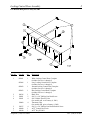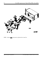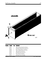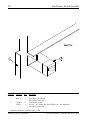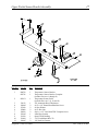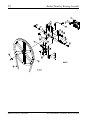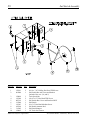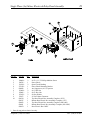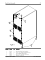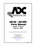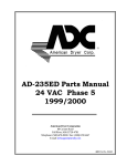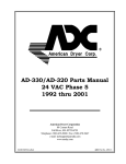
1
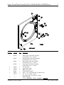
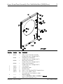
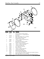
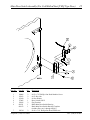
AD-236 Parts Manual
24 VAC Phase 5
American Dryer Corporation
88 Currant Road
Fall River, MA 02720-4781
Telephone: (508) 678-9000 / Fax: (508) 678-9447
E-mail: [email protected]
www.amdry.com
072400JO/tcosta
ADC Part No. 450347
Retain This Manual In A Safe Place For Future Reference
American Dryer Corporation products embody advanced concepts in engineering, design, and safety. If this product is
properly maintained, it will provide many years of safe, efficient, and trouble free operation.
ONLY qualified technicians should service this equipment.
OBSERVE ALL SAFETY PRECAUTIONS displayed on the equipment or specified in the installation manual included with
the dryer.
The following “FOR YOUR SAFETY” caution must be posted near the dryer in a prominent location.
FOR YOUR SAFETY
POUR VOTRE SÉCURITÉ
Do not store or use gasoline or
other flammable vapors and
liquids in the vicinity of this or
any other appliance.
Ne pas entreposer ni utiliser d’essence
ni d’autres vapeurs ou liquides
inflammables à proximité de cet
appareil ou de tout autre appareil.
We have tried to make this manual as complete as possible and hope you will find it useful. ADC reserves the right to make
changes from time to time, without notice or obligation, in prices, specifications, colors, and material, and to change or
discontinue models.
Important
For your convenience, log the following information:
DATE OF PURCHASE ___________________________
RESELLER’S NAME
Serial Number(s)
AD-236
MODEL NO. __________________________________________
______________________________________________________________________________________
________________________________________________________________________________________
________________________________________________________________________________________
________________________________________________________________________________________
Replacement parts can be obtained from your reseller or the ADC factory. When ordering replacement parts from the factory,
you can FAX your order to ADC at (508) 678-9447 or telephone your order directly to the ADC Parts Department at (508)
678-9000. Please specify the dryer model number and serial number in addition to the description and part number, so that
your order is processed accurately and promptly.
The illustrations on the following pages may not depict your particular dryer exactly. The illustrations are a composite of the
various dryer models. Be sure to check the descriptions of the parts thoroughly before ordering.
“IMPORTANT NOTE TO PURCHASER”
Information must be obtained from your local gas supplier on the instructions
to be followed if the user smells gas. These instructions must be posted in a
prominent location near the dryer.
Table of Contents
Coin Control Door Assembly
For Models Mfd. as of May 30, 2003 ...................................................................................................... 2
Locking Control Door Assembly
For Models Mfd. prior to May 30, 2003 .................................................................................................. 3
Coin Microprocessor Control Panel/Box Assemblies ................................................................................. 4, 5
Upper Front Panel Assembly (For Plastic Door) ........................................................................................... 6
Upper Front Panel Assembly (For Cold Rolled Steel [CRS] Door) ................................................................ 7
Lower Front Panel Assembly (For Plastic Door) ........................................................................................... 8
Lower Front Panel Assembly (For Cold Rolled Steel [CRS] Door)................................................................ 9
Plastic Main Door Assembly ....................................................................................................................... 10
Main Door “Steel” Assembly .......................................................................................................................11
Main Door Switch Assembly (For Plastic Door) .......................................................................................... 12
Main Door Switch Assembly (For Cold Rolled Steel [CRS] Type Door) ...................................................... 13
Basket (Tumbler)/Support Assembly ........................................................................................................... 14
Lint Drawer Assembly ................................................................................................................................ 15
Lint Drawer Switch Assembly ..................................................................................................................... 16
Upper Pocket Sensor Bracket Assembly ..................................................................................................... 17
Lower Pocket Sensor Bracket Assembly .................................................................................................... 18
Idler Bearing Assembly ............................................................................................................................... 19
Basket (Tumbler) Bearing Assembly ...................................................................................................... 20, 21
T.E.F.C. Motor Mount Assembly ............................................................................................................ 22, 23
Direct Spark Ignition (DSI) Gas Valve/Burner Assembly ........................................................................ 24, 25
Gas Piping Assembly .................................................................................................................................. 26
Gas Burner Assembly ................................................................................................................................. 27
Sail Switch Assembly .................................................................................................................................. 28
Single Phase (1ø) Motor, Electrical Relay Panel Assembly .......................................................................... 29
3-Phase (3ø) Motor, Electrical Relay Panel Assembly ................................................................................. 30
Back Guard Assembly ................................................................................................................................ 31
Exhaust Ducting Assembly .......................................................................................................................... 32
Additional Parts Available............................................................................................................................ 33
2
Coin Control Door Assembly
For Models Mfd. as of May 30, 2003
Illus. No.
Part No.
Qty.
1
2
3
160040
160140
883896
1
1
1
883897
1
883898
1
150314
154011
117604
4
4
3
4
5
6
American Dryer Corporation
Description
ACE® Control Door Lock
ACE® Key XX4451
White Locking Control Door Complete
(includes illus. nos. 1 through 3 and 6)
Ivory Locking Control Door Complete
(includes illus. nos. 1 through 3 and 6)
Blue Locking Control Door Complete
(includes illus. nos. 1 through 3 and 6)
#10-32 x 1/2” Torx + Screw
#10-32 Multi-Thread U-Nut
Noise Suppression Tape
88 Currant Road / Fall River, MA 02720-4781
Locking Control Door Assembly
3
For Models Mfd. prior to May 30, 2003
Illus. No.
Part No.
Qty.
1
882691
1
883466
1
882692
1
882693
1
180516
150201
154011
1
5
4
154009
4
150217
160040
160140
4
1
1
2
3
4
5
6
7
Telephone: (508) 678-9000
Description
White Locking Control Door Complete
(includes illus. nos. 1 through 3)
Ivory Locking Control Door Complete
(includes illus. nos. 1 through 3)
Almond Locking Control Door Complete
(includes illus. nos. 1 through 3)
Blue Locking Control Door Complete
(includes illus. nos. 1 through 3)
Black Trim
#10-32 x 1/4” Phillips Pan Head Screw
#10-32 Multi-Thread U-Nut
(for models mfd. as of January 4, 2001)
Tinnerman Clips
(for models mfd. prior to January 4, 2001)
#10-32 x 3/4” Phillips Pan Head Machine Screw
ACE® Control Door Lock
ACE® Key XX4451
Fax: (508) 678-9447
4
Coin Microprocessor Control Panel/Box Assemblies
NOTE: Duplicate ALL components for right hand side of control box.
American Dryer Corporation
88 Currant Road / Fall River, MA 02720-4781
5
Coin Microprocessor Control Panel/Box Assemblies
Illus. No.
Part No.
Qty.
1
2
112526
882694
1
1
3
882695
1
883467
1
882696
1
882697
1
160042
1
160136*
1
881163
1
881143
1
137021**
3
137023**
1
880772
1
824080
1
137213
1
824998
1
153010
2
150005
2
122706
15
122641
1
122800
1
136057
1 or 2
150002
1 or 2
136008
1 or 2
141403
1
150301
2
150301
2
353258
1
826343
1
4
5
6
7
8
9
10
11
12
13
14
15
16
17
18
19
20
21
22
23
24
25
826342
1
151001
882699
882700
883899
882701
152014
6
1
1
1
1
4
Description
Coin Keyboard (touch pad) Label Assembly
Control Panel Assembly Less Acceptor
(includes illus. nos. 1, 2, and 10 through 12)
White Coin Box
Ivory Coin Box
Almond Coin Box
Blue Coin Box
ACE® Standard Coin Box Lock Assembly with Key
Key (for standard coin box lock)
Microprocessor Single Coin Acceptor with Optical Switch
Optical Switch
Microprocessor Socket
Optical Switch Connector
Single Coin Optic Switch Harness
Dual Coin Optic Switch Harness
Phase 5 Coin Controller
Phase 5 Battery Clip
#6 Star Washer
#6-32 x 1/4” Phillips Round Head Machine Screw
Microprocessor Socket
15-Pin Microprocessor Connector
Microprocessor (female) Pin Extraction Tool
1/2-Amp (Slo-Blo) Fuse
#6-32 x 1” Round Head Machine Screw
Fuse Block
24 volt Transformer
#8-18 x 7/16” Phillips Pan Head TEK Screw
#8-18 x 7/16” Phillips Pan Head TEK Screw
Plug Retainer Bracket
Control Box Panel Assembly Complete (115 volt)
(includes illus. nos. 15 through 22)
Control Box Panel Assembly Complete (208-240 volt)
(includes illus. nos. 15 through 22)
#8-32 Pal Nut
White Coin Vault
Almond Coin Vault
Ivory Coin Vault
Blue Coin Vault
1/4-20 Hex Flange Nut
* Specify key number when ordering.
** For dual coin, double the quantity.
IMPORTANT: Check label on computer chip to verify correct part number for controller (computer).
Telephone: (508) 678-9000
Fax: (508) 678-9447
6
Upper Front Panel Assembly (For Plastic Door)
Illus. No.
Part No.
Qty.
1
882705
1
882706
1
882707
1
883469
1
154215
170330
112350
870011
150309
150313
2
1
1
1
8
8
121405
1
2
3
4
5
6
American Dryer Corporation
Description
White Upper Front Panel Assembly
(includes illus. nos. 1, 2, 3, and 6)
Almond Upper Front Panel Assembly
(includes illus. nos. 1, 2, 3, and 6)
Blue Upper Front Panel Assembly
(includes illus. nos. 1, 2, 3, and 6)
Ivory Upper Front Panel Assembly
(includes illus. nos. 1, 2, 3, and 6)
1/4” Pop Rivet
Friction Door Latch
ADC Logo ONLY
Logo Double Tape Kit
#10-16 x 1/2” Hex Head TEK Crimptite Screw
#10-16 x 1/2” TORX + Screw
(for models mfd. as of October 2, 2000)
Rubber Grommet
88 Currant Road / Fall River, MA 02720-4781
Upper Front Panel Assembly (For Cold Rolled Steel [CRS] Door)
Illus. No.
Part No.
Qty.
1
883260
1
883262
1
883261
1
883468
1
154215
170330
112350
870011
150309
150313
2
1
1
1
8
8
--------
--
2
3
4
5
6
Telephone: (508) 678-9000
7
Description
White Upper Front Panel Assembly
(includes illus. nos. 1, 2, and 3)
Almond Upper Front Panel Assembly
(includes illus. nos. 1, 2, and 3)
Blue Upper Front Panel Assembly
(includes illus. nos. 1, 2, and 3)
Ivory Upper Front Panel Assembly
(includes illus. nos. 1, 2, and 3)
1/4” Pop Rivet
Friction Door Latch
ADC Logo ONLY
Logo Double Tape Kit
#10-16 x 1/2” Hex Head TEK Crimptite Screw
#10-16 x 1/2” TORX + Screw
(for models mfd. as of October 2, 2000)
Main Door Hinge
(refer to Main Door “Steel” Assembly on page 11)
Fax: (508) 678-9447
8
Lower Front Panel Assembly (For Plastic Door)
Illus. No.
Part No.
Qty.
1
882702
1
882703
1
882704
1
883470
1
2
3
4
5
154215
170330
315187
150309
150313
2
1
1
14
14
6
7
121405
882602
1
1
American Dryer Corporation
Description
White Lower Front Panel Assembly
(includes illus. nos. 1 through 4, 6, and 7)
Almond Lower Front Panel
(includes illus. nos. 1 through 4, 6, and 7)
Blue Lower Front Panel
(includes illus. nos. 1 through 4, 6, and 7)
Ivory Lower Front Panel
(includes illus. nos. 1 through 4, 6, and 7)
1/4” Pop Rivet
Friction Door Latch
Kick Plate Trim
#10-16 x 1/2” Hex Head TEK Crimptite Screw
#10-16 x 1/2” TORX + Screw
(for models mfd. as of October 2, 2000)
Rubber Grommet
Black Lower Front Panel Trim
88 Currant Road / Fall River, MA 02720-4781
Lower Front Panel Assembly (For Cold Rolled Steel [CRS] Door)
Illus. No.
Part No.
Qty.
1
883479
1
883481
1
883480
1
883468
1
2
3
4
5
154215
170330
315187
150309
150313
2
1
1
14
14
6
--------
--
7
882602
1
Telephone: (508) 678-9000
9
Description
White Lower Front Panel Assembly
(includes illus. nos. 1 through 4 and 7)
Almond Lower Front Panel
(includes illus. nos. 1 through 4 and 7)
Blue Lower Front Panel
(includes illus. nos. 1 through 4 and 7)
Ivory Lower Front Panel
(includes illus. nos. 1 through 4 and 7)
1/4” Pop Rivet
Friction Door Latch
Kick Plate Trim
#10-16 x 1/2” Hex Head TEK Crimptite Screw
#10-16 x 1/2” TORX + Screw
(for models mfd. as of October 2, 2000)
Main Door Hinge
(refer to Main Door “Steel” Assembly on page 11)
Black Lower Front Panel Trim
Fax: (508) 678-9447
10
Plastic Main Door Assembly
Illus. No.
Part No.
Qty.
1
881422
1
2
3
4
5
6
800448
150410
152014
102349
102212
170731
150448
170319
150431
4
4
1
1
1
1
4
4
1
7
8
9
American Dryer Corporation
Description
Black Plastic Main Door Assembly Complete with Mechanical Fasteners
(includes illus. nos. 1 and 5 through 9)
12-1/2” Stainless Steel Main Door Hinge Assembly
#10-24 x 3/8” Phillips Pan Head Taptite Screw
1/4-20 Free Spin Wash Nut
Main Door Gasket
20-7/16” Door Glass with (4) Holes
Main Door Glass Adhesive (10.3 oz. cartridge)
1/2” Stainless Steel Flat Head Allen Screw
Door Glass (nylon) Spacer
Main Door Latch Screw
(#10 x 7/16” dome hex head)
88 Currant Road / Fall River, MA 02720-4781
11
Main Door “Steel” Assembly
Illus. No.
Part No.
Qty.
1
881150
1
2
3
102354
170731
881152
1
1
1
4
5
6
150445
153031
881151
2
1
1
7
8
9
10
11
12
13
14
15
150445
150683
152014
151010
150120
150683
152014
881210
102211
102218
170731
151013
2
3
3
1
1
3
3
1
1
1
1
4
16
Telephone: (508) 678-9000
Description
Black Main Door Assembly Complete
(includes illus. nos. 1, 2, and 8 through 15)
Door Gasket
Black Gasket Adhesive (10.3 oz. cartridge)
Black Top Hinge Block Assembly
(includes illus. nos. 3 and 4)
1/4-20 x 3/4” Black Cap Head Setscrew
1/4” Nylon Washer
Black Bottom Hinge Block Assembly
(includes illus. nos. 5 through 7)
1/4-20 x 3/4” Black Cap Head Setscrew
1/4-20 x 5/8” Black Carriage Bolt
1/4-20 Free Spin Wash Nut
#10-32 Black Hex Acorn Nut
Door Latch Screw
1/4-20 x 5/8” Black Carriage Bolt
1/4-20 Free Spin Wash Nut
Black Main Door Handle ONLY
20-7/16” Door Glass without Holes
20-7/16” Door Glass with Holes (for models with mechanical fasteners)
Black Glass Adhesive (10.3 oz. cartridge)
#10-32 Black Nylon Acorn Nut (for models with mechanical fasteners)
Fax: (508) 678-9447
12
Main Door Switch Assembly (For Plastic Door)
NOTE: Duplicate ALL components for
Lower Door Switch Assembly.
Illus. No.
Part No.
Qty.
1
2
3
4
5
6
152013
153008
137005
121028
154281
800448
2
2
1
2
2
1
7
8
9
10
153565
881246
150201
121405
2
1
2
1
American Dryer Corporation
Description
#6-32 Hex Nut
#6 Lock Washer
Single Pole Door Switch
Insulated Terminal
3/8” Standard Nylon Spacer
12-1/2” Stainless Steel Main Door Hinge Assembly
(includes illus. nos. 6 and 7)
#6 Stud
Main Door Switch Housing
#10-32 x 1/4” Phillips Pan Head Screw
Rubber Grommet
88 Currant Road / Fall River, MA 02720-4781
Main Door Switch Assembly (For Cold Rolled Steel [CRS] Type Door)
Illus. No.
Part No.
Qty.
1
2
3
4
5
6
150006
152013
153010
137005
122636
881211
881153
2
2
2
1
2
1
1
7
150301
2
Telephone: (508) 678-9000
13
Description
#6-32 x 7/8” Phillips Pan Head Machine Screw
#6-32 Hex Nut
#6 Star Washer
Door Switch ONLY
Flag Terminal
Black Main Door Switch Housing
Black Main Door Switch Housing Complete
(includes illus. nos. 1 through 4 and 6)
#8-18 x 7/16” Phillips Pan Head TEK Screw
Fax: (508) 678-9447
14
Basket (Tumbler)/Support Assembly
Illus. No.
Part No.
Qty.
1
800831
1
800721*
1
800891
1
800841*
1
301315
301316
301414
301415
150518
100915
153004
154210
800617
152027
153005
153004
116003
401010
2
1
2
1
1
3
3
30
1
3
3
3
1
1
2
3
4
5
6
7
8
9
10
11
*
Description
Basket (tumbler) and Support Assembly Complete with Felt Collar
(includes illus. nos. 1 through 11)
Basket (tumbler) ONLY
(includes illus. nos. 1, 2, and 6)
Stainless Steel Basket (tumbler) and Support Assembly Complete with Felt
Collar
(includes illus. nos. 1 through 11)
Stainless Steel Basket (tumbler) ONLY
(includes illus. nos. 1, 2, and 6)
Short Basket (tumbler) Rib ONLY
Tall Basket (tumbler) Rib ONLY
Stainless Steel Short Basket (tumbler) Rib ONLY
Stainless Steel Tall Basket (tumbler) Rib ONLY
5/16-18 x 3/8” Socket Button Head Screw
3/8-16 x 31” Tie Rod
3/8” Flat Washer
5/32” x 3/16” Pop Rivet
Basket (tumbler) Support ONLY
3/8-16 Hex Nut
3/8” Lock Washer
3/8” Flat Washer
Felt Collar ONLY
#847 Adhesive for Felt Collar (5 oz. tube) – Not Illustrated
Felt collar is not included and must be ordered separately.
American Dryer Corporation
88 Currant Road / Fall River, MA 02720-4781
15
Lint Drawer Assembly
Illus. No.
Part No.
Qty.
1
883995
882712
883996
883994
882708
882709
882710
883472
882478
1
1
1
1
1
1
1
1
1
2
Telephone: (508) 678-9000
Description
White Locking External Lint Drawer
Almond Locking External Lint Drawer
Blue Locking External Lint Drawer
Ivory Locking External Lint Drawer
White External Lint Drawer
Almond External Lint Drawer
Blue External Lint Drawer
Ivory External Lint Drawer
Lint Drawer Lock Assembly
Fax: (508) 678-9447
16
Lint Drawer Switch Assembly
Illus. No.
Part No.
Qty.
1
800972
1
2
122002*
150301
1
1
*
Description
Lint Drawer Switch Box
(for bottom pocket Only)
Lint Drawer Switch
#8-18 x 7/16” Phillips Pan Head TEK Screw – Not Illustrated
(for bottom pocket Only)
Duplicate lint drawer switch for upper pocket.
American Dryer Corporation
88 Currant Road / Fall River, MA 02720-4781
Upper Pocket Sensor Bracket Assembly
Illus. No.
Part No.
Qty.
1
800769
882726
1
1
2
882931
1
3
4
5
6
7
8
9
10
11
130112
150005
153010
152000
150309
122605
121300
121494
154007
1
2
2
2
2
1
1
2
2
Telephone: (508) 678-9000
17
Description
Temperature Sensor Bracket
Temperature Sensor Bracket Complete
(includes illus. nos. 1 through 11)
Temperature Sensor Probe
(includes illus. nos. 2, 8, 10, and 11)
225º Automatic Reset Thermostat
#6-32 x 1/4” Round Head Machine Screw
#6 Star Washer
#6-32 Hex Nut
#10-16 x 1/2” Hex Head TEK Crimptite Screw
4-Pin Plug (female)
Open/Closed Bushing
3/16” Push Mount Wire Tie
1/4” Push On Fastener
Fax: (508) 678-9447
18
Lower Pocket Sensor Bracket Assembly
Illus. No.
Part No.
Qty.
1
800770
882727
1
1
2
882931
1
3
4
5
6
7
8
9
10
11
130112
150005
153010
152000
150309
122605
121300
121494
154007
1
2
2
2
2
1
1
2
2
American Dryer Corporation
Description
Temperature Sensor Bracket ONLY
Temperature Sensor Bracket Complete
(includes illus. nos. 1 through 11)
Temperature Sensor Probe
(includes illus. nos. 2, 8, 10, and 11)
225º Automatic Reset Thermostat
#6-32 x 1/4” Round Head Machine Screw
#6 Star Washer
#6-32 Hex Nut
#10-16 x 1/2” Hex Head TEK Crimptite Screw
4-Pin Connector (female)
Open/Closed Bushing
3/16” Push Mount Wire Tie
1/4” Push On Fastener
88 Currant Road / Fall River, MA 02720-4781
19
Idler Bearing Assembly
Illus. No.
Part No.
Qty.
1
2
3
4
5
6
7
8
9
10
100111
101129
100113
100115
154301
100705
882777
150617
153005
153004
---------
1
1
1
1
2
1
1
2
2
2
-
11
12
152004
150509
1
1
Telephone: (508) 678-9000
Description
5L-650 V-Belt (to basket [tumbler] pulley)
9” x 2-1/2” Pulley with 3/16” Key
4L-400 V-Belt (to motor pulley) for 60 Hz Models ONLY
4L-410 V-Belt (to motor pulley) for 50 Hz Models ONLY
5/16-18 x 1” Allen Setscrew
3/16” x 3/16” x 1-3/8” Key
Idler Bearing Assembly Complete
3/8-16 x 1” Hex Head Machine Bolt
3/8” Lock Washer
3/8” Flat Washer
Direct Spark Ignition (DSI) Module Mounting Bracket
(refer to Direct Spark Ignition [DSI] Gas Valve/Burner Assembly
on page 24 and page 25)
5/16-18 Hex Nut
5/16-18 x 3” Hex Head Machine Bolt
Fax: (508) 678-9447
20
Basket (Tumbler) Bearing Assembly
American Dryer Corporation
88 Currant Road / Fall River, MA 02720-4781
Basket (Tumbler) Bearing Assembly
Illus. No.
Part No.
Qty.
1
2
3
4
880203
153005
152005
882544
1
4
4
1
882545
1
882542
882543
1
1
5
880202
880779
1
1
6
7
8
9
10
11
12
13
14
15
150601
153004
153005
152005
154326
152004
150621
153002
150501
102120
2
8
2
2
2
4
2
4
4
1
16
824807
1
17
18
19
20
100713
101100
100111
150610
1
1
1
2
Telephone: (508) 678-9000
21
Description
1-3/8” Flange Bearing
3/8” Lock Washer
3/8-16 Hex Nut
Pillow Block Bearing Assembly Complete
(includes illus. nos. 4 through 14 and 20)
Pillow Block Bearing Assembly Complete
(for models mfd. with rotational sensor)
(includes illus. nos. 4 through 16 and 20)
Pillow Block Bearing Support ONLY
Pillow Block Bearing Support ONLY
(for models mfd. with rotational sensor)
1-3/8” Pillow Block Bearing
1-3/8” Pillow Block Bearing
(for models mfd. with rotational sensor)
3/8-16 x 2” Hex Bolt
3/8” Flat Washer
3/8” Lock Washer
3/8-16 Hex Nut
5/16-24 x 3/8” Black Setscrew
5/16-18 Hex Nut
5/16-18 x 1-1/2” Tap Bolt
5/16” Lock Washer
5/16-18 x 3/4” Tap Bolt
Sintered 8 Magnet
(for models mfd. with rotational sensor)
Rotational Sensor Assembly
(for models mfd. with rotational sensor)
1/4” x 1/4” x 7/8” Key
18” Pulley
5L-650 V-Belt (to idler assembly)
5/16-18 x 1-1/2” Allen Setscrew
Fax: (508) 678-9447
22
T.E.F.C. Motor Mount Assembly
Illus. No.
Part No.
Qty.
1
2
3
4
5
6
7
100604
152006
153050
100702
153050
117604
800965
803967
1
2
*
1
*
4
1
1
822526
1
803968**
1
803902**
1
American Dryer Corporation
Description
12-1/2” Impellor with 1/2” Bore
1/2-20 Left Hand Jam Nut
1/2” S.A.E. Flat Washer
1/8” x 1/8” x 1-1/2” Key
1/2” S.A.E. Flat Washer
Noise Suppression Tape (sold by the foot)
Motor Mount ONLY
1/2 HP 115-230v 1ø 60 Hz
Motor Mount Assembly Complete with Plug Motor
(includes illus. nos. 1 through 7 and 11 through 17)
1/2 HP 240v 1ø 50 Hz Totally Enclosed, Fan-Cooled (T.E.F.C.) Motor
Mount Assembly Complete with Plug Motor
(includes illus. nos. 1 through 7 and 11 through 17)
1/2 HP 208/230/380/460v 3ø 60 Hz Totally Enclosed, Fan-Cooled
(T.E.F.C.) Motor Mount Assembly Complete
(includes illus. nos. 1 through 7, 11, 13 through 17, 22, and 23)
1/2 HP 208/230/380/460v 3ø 50 Hz Totally Enclosed, Fan-Cooled
(T.E.F.C.) Motor Mount Assembly Complete
(includes illus. nos. 1 through 7, 11, 13 through 17, 22, and 23)
88 Currant Road / Fall River, MA 02720-4781
23
T.E.F.C. Motor Mount Assembly (continued)
Illus. No.
Part No.
Qty.
8
9
10
11
12
150501
153002
153001
154000
181049
883629
4
4
4
4
1
1
13
14
15
16
17
150501
153002
153001
153001
101131
101133
101125
4
4
4
*
1
1
1
101130
1
22
100113
100115
122701
137030
122801
837005
837006
100007**
1
1
8
1
1
1
1
1
23
24
120200
100701
1
1
18
19
20
21
Description
5/16-18 x 3/4” Hex Head Machine Bolt
5/16” Lock Washer
5/16” Flat Washer
5/16-18 Tinnerman Nut
1/2 HP 100-230v 1ø 50/60 Motor with Plug
1/2 HP 240v 1ø 50 Hz Motor with Plug
(for models mfd. prior to August 22, 2002)
5/16-18 x 3/4” Hex Head Machine Bolt
5/16” Lock Washer
5/16” Flat Washer
5/16” Flat Washer
1/2” x 2-1/4” Motor Pulley (for use on 1ø, 60 Hz models Only)
5/8” x 2-1/4” Motor Pulley (for use on 3ø, 60 Hz models Only)
1/2” x 2-1/2” Motor Pulley (for use on 1ø, 50 Hz models Only)
(for models mfd. as of August 22, 2002)
5/8” x 2-1/2” Motor Pulley (for use on 3ø, 50 Hz models and 1ø, 50 Hz
models)
(for models mfd. prior to August 22, 2002)
4L-400 V-Belt (to idler) for 60 Hz Models ONLY
4L-410 V-Belt (to idler) for 50 Hz Models ONLY
Socket Terminal
8-Pin Housing
Pin/Socket Extraction Tool – Not Illustrated
120v 1ø Motor Harness with Plug
230v 1ø Motor Harness with Plug
1/2 HP 208/230/380/460v 3ø 50/60 Hz Totally Enclosed, Fan-Cooled
(T.E.F.C.) Motor
3/8” x 90º Connector
3/16” x 3/16” x 1” Key (for use on 3ø models Only)
* As required.
** Specify voltage when ordering.
Telephone: (508) 678-9000
Fax: (508) 678-9447
24
Direct Spark Ignition (DSI) Gas Valve/Burner Assembly
American Dryer Corporation
88 Currant Road / Fall River, MA 02720-4781
Direct Spark Ignition (DSI) Gas Valve/Burner Assembly
Illus. No.
Part No.
Qty.
1
824142
809313*
1
1
809314*
1
882396**
150300
141317
1
2
1
881367
1
318650
150301
128927
880960
318650
150301
141235
140829
140814
153012
152001
141131
1
2
1
1
1
2
1
1
1
1
1
1
318009
--------***
150315
128917
305412
128918
121028
132607
121028
128935
1
1
2
1
1
1
1
2
1
1
882627
1
152013
824131
2
1
2
3
4
5
6
7
8
9
10
11
12
13
14
15
16
17
18
19
20
21
22
23
24
25
Description
Gas Valve/Burner Tube Mounting Plate ONLY
Natural Gas - Gas Valve/Burner Assembly Complete Less Orifice
(includes illus. nos. 1 and 3 through 18)
Liquid Propane (L.P.) Gas Valve/Burner Assembly Complete Less Orifice
(includes illus. nos. 1 and 3 through 18)
Liquid Propane (L.P.) Conversion Kit with Orifice
#10-16 x 1/2” Hex Washer TEK Screw
1/2 Union Elbow
(for models mfd. as of June 30, 2003)
Union Shutoff with 1/2” Tailpiece
(for models mfd. prior to June 30, 2003)
Notched Pipe Bracket
#8-18 x 7/16” Phillips Pan Head TEK Screw
1/2” 24 VAC (natural gas) Gas Valve
1/2” 24 VAC Liquid Propane (L.P.) Gas Valve
Notched Pipe Bracket
#8-18 x 7/16” Phillips Pan Head TEK Screw
1/2” Single Port Manifold
#18 Burner Orifice (natural gas Only)
#38 Burner Orifice (liquid propane [L.P.] gas Only)
#8 Steel Burr
#8-32 Hex Nut
Up-Shot Burner Tube
(includes illus. no. 15)
Burner Tube Bracket
Flame Spreader
#6 x 3/8” Phillips Pan Head Machine Screw
Spark Electrode with High Voltage (HV) Wire
Direct Spark Ignition (DSI) Ignitor Gap Feeler Gauge – Not Illustrated
Flame Sensor Probe
1/4” Insulated Terminal
#18 Gauge Red Silicone Wire (sold by the foot)
1/4” x 0.032 Insulated Terminal
Direct Spark Ignition (DSI) Module with Three (3) Tries
(for models mfd. as of April 14, 2000)
Direct Spark Ignition (DSI) Module Conversion Kit
(for models mfd. prior to April 14, 2000)
#6-32 Hex Nut
Direct Spark Ignition (DSI) Module Mounting Bracket
* Burner orifice is not included and must be ordered separately.
** Consult factory for elevations over 2,000 feet.
*** Not sold separately.
Telephone: (508) 678-9000
Fax: (508) 678-9447
26
Gas Piping Assembly
Illus. No.
Part No.
Qty.
1
2
3
318702
150300
141236
1
2
1
American Dryer Corporation
Description
Top Pipe Support Bracket ONLY
#10-16 x 1/2” Hex Washer TEK Screw
Gas Piping Manifold
88 Currant Road / Fall River, MA 02720-4781
27
Gas Burner Assembly
Illus. No.
Part No.
Qty.
1
800526
1
2
3
4
318006
150300
802502
1
2
1
5
6
7
8
319710
150301
150001
130301
151000
1
2
2
1
2
Telephone: (508) 678-9000
Description
Gas Burner Chamber Assembly
(includes illus. nos. 1 through 3)
Flame Viewing Plate
#10-16 x 1/2” Hex Washer TEK Screw
Hi-Limit Bracket Assembly
(includes illus. nos. 4 through 8)
Hi-Limit Bracket ONLY
#8-18 x 7/16” Phillips Pan Head TEK Screw
#6-32 x 1/2” Right Hand Machine Screw
225º Hi-Limit Thermostat
#6-32 Pal Nut
Fax: (508) 678-9447
28
Sail Switch Assembly
Illus. No.
Part No.
Qty.
1
2
150301
802800
2
1
3
4
5
6
7
8
9
10
154004
150300
802799
122200
150303
105500
319202
154002
1
2
1
1
2
1
1
1
American Dryer Corporation
Description
#8-18 x 7/16” Phillips Pan Head TEK Screw
Sail Switch Box with Cover and Bracket
(includes illus. nos. 2, 4, and 5)
Twin Speed Nut
#10-16 x 1/2” Hex Head TEK Screw
Sail Switch Box Cover and Bracket ONLY
Sail Switch
#4 x 3/4” Pan Head Machine Screw
Sail Switch Actuator Rod
Sail Switch Damper
1/8” Push On Fastener
88 Currant Road / Fall River, MA 02720-4781
29
Single Phase (1ø) Motor, Electrical Relay Panel Assembly
Illus. No.
Part No.
Qty.
1
2
3
4
5
6
7
8
9
10
150009*
120701*
121300*
353142*
824828
151000*
152001*
153012*
132475
826324
826347
826422
826421
850474
2
1
2
1
1
2
2
2
1
1
1
1
1
1
*
Description
#6-32 x 1-1/2” Phillips Machine Screw
Power Block
Open/Closed Bushing
Power Block Mounting Bracket
Arc Suppressor (A.S.) Capacitor
#6-32 Pal Nut
#8-32 Hex Nut
#8 Star Washer
24 VAC Motor Contactor
Top Rear Electric Box Assembly Complete (115V)
Bottom Rear Electric Box Assembly Complete (115V
Top Rear Electric Box Assembly Complete (208-240V)
Bottom Rear Electric Box Assembly Complete (208-240V)
Rear Electric Box ONLY
Parts for top pocket electric box only.
Telephone: (508) 678-9000
Fax: (508) 678-9447
30
3-Phase (3ø) Motor, Electrical Relay Panel Assembly
Illus. No.
Part No.
Qty.
1
2
3
4
5
6
7
8
9
10
150009*
120701*
121300*
353142*
137015
151000*
152001*
153012*
132447
826340
826348
850474
4
2
3
2
1
4
4
4
1
1
1
1
*
Description
#6-32 x 1-1/2” Phillips Machine Screw
Power Block
Open/Closed Bushing
Power Block Mounting Bracket
Arc Suppressor (A.S.) Capacitor ONLY
#6-32 Pal Nut
#8-32 Hex Nut
#8 Star Washer
24 VAC Motor Contactor
Top Rear Electric Box Assembly Complete
Bottom Rear Electric Box Assembly Complete
Rear Electric Box ONLY
Parts for top pocket electric box only.
American Dryer Corporation
88 Currant Road / Fall River, MA 02720-4781
31
Back Guard Assembly
Illus. No.
Part No.
Qty.
1
2
3
4
5
311014
150301
318702
150300
103500
2
16
1
2
4
Telephone: (508) 678-9000
Description
Upper/Lower Back Guard Assembly
#8-18 x 7/16” Phillips Pan Head TEK Screw
Top Pipe Support Bracket ONLY
#10-16 x 1/2” Hex Washer TEK Screw
Adjustable Leveling Leg
Fax: (508) 678-9447
32
Exhaust Ducting Assembly
Illus. No.
Part No.
Qty.
1
2
3
4
5
6
7
880505
143527
143539
143537
143538
143536
315062
150300
143536
315062
150300
117505
1
1
1
1
1
2
1
2
2
1
2
*
8
9
*
Description
Wye Branch Damper Assembly
6” Round x 7” Oval Straight Boot
15-1/2” Long x 7” Oval Duct
7” Oval x 45º Elbow
6” Round x 7” Oval Straight Boot
6” Round x 45º Elbow
Rear Wiring Box Cover ONLY
#10-16 x 1/2” Hex Washer TEK Screw – Not Illustrated
6” Round x 45º Elbow
Rear Wiring Box Cover ONLY
#10-16 x 1/2” Hex Washer TEK Screw – Not Illustrated
Aluminum Duct Tape (sold by the foot) – Not Illustrated
As required.
American Dryer Corporation
88 Currant Road / Fall River, MA 02720-4781
Additional Parts Available
Part No.
Description
114533
112280
112533
114001
114006
120100
120300
120400
120500
120600
120800
120802
120902
120903
121006
121014
121499
121500
121503
122804
170194
404502
404506
404507
404516
“Black/White/Green Ground” Label
“Clean Lint Screen” Label
“Phase 5 Coin Program Location Summary” Label
“Caution - Exhaust/Lint Screen” Label
“Warning - Fire Hazards” Label
3/8” Straight (BX) Connector
3/8” x 45º (BX) Connector
3/8” Red Jacket (BX) Insulator
3/8” Jiffy Clip (BX Retainer Clip)
3/8” Greenfield (BX)
1/4” In-Line Connector
Red Butt Connector
#74B Wire Nut
Crimp-On Wire Nut
#10 Insulated Ring Terminal
1/4” Insulated (female) Terminal
5-1/2” Harness Tie
8” Harness Tie
Harness Tie Mounting Clip
Manometer (water column test gauge)
Basket (tumbler) Lint Cleaning Brush
White Brush-In-Cap Bottle Touch-Up Paint
Almond “B” Brush-In-Cap Bottle Touch-Up Paint
Cornflower Blue Brush-In-Cap Bottle Touch-Up Paint
Ivory Brush-In-Cap Bottle Touch-Up Paint
Telephone: (508) 678-9000
33
Fax: (508) 678-9447
ADC 450347
8 - 08/18/04-1