1
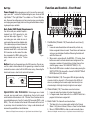
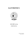
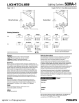
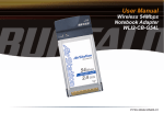
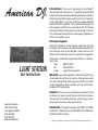
American DJ
®
Introduction: Thank you for purchasing the Light Station™
DMX controller from American DJ®. To optimize the performance
of this product, please read these operating instructions carefully to
familiarize yourself with the basic operations of this unit. The American DJ® Light Station™ is a unique, 16 channel programmable DMX
controller with MIDI capabilities. This unit features 60 programs, 30
built in programs and 30 that you can create yourself. This unit also
comes with a memory back up battery to save and retain your data.
This unit has been tested at the factory before being shipped to you,
there is no assembly required.
Customer Support:
LIGHT STATION
User Instructions
American DJ provides a toll free customer support line, to provide
set up help and to answer any question should you encounter problems during your set up or initial operation. You may also visit us on
the web at www.americandj.com for any comments or suggestions.
Service Hours are Monday through Friday 10:00 a.m. to 5:00 p.m.
Pacific Time.
Voice:
(800) 322-6337
Fax:
(323) 582-2610
E-mail:
[email protected]
Warning! To prevent or reduce the risk of electrical shock or fire,
do not expose this unit to rain or moisture. Clearing memory often
may cause damage to the memory chip, be careful not to re initialize your unit frequency often to avoid this risk. Only use the recommended AC/DC power adaptor.
Caution! There are no user serviceable parts inside this unit. Do
American DJ Supply
4295 Charter Street
Los Angeles Ca 90058
(323) 582-2650
(323) 582-2610
www.americandj.com
not attempt any repairs yourself, doing so will void your manufactures warranty. In the unlikely event your unit may require service,
please contact your nearest American DJ dealer.
Conformity: This product complies to EN 50081-1/EN 55022
pr EN 55103-1 (EMC emission) and EN 50082-1/EN 61000-4-2 pr
EN 55103-2 (EMC immunity).
©American DJ Suply® www-americandj.com Light Stantion Instruction Manual Page 2
Function and Controls - Front Panel
Set Up:
Power Supply: Before plugging your unit in be sure the source volt-
age in your area matches the required voltage for your American DJ®
Light Station.™ The Light Station™ is available in a 115v and 230v version. Because line voltage may vary from venue to venue, you should be
sure to plug your power supply into a matching wall outlet before attempting to operate you controller.
1
2
3
1
2
3
4
4
5
6
7
5
MASTER
M
8
10
10
10
10
10
10
10
10
8
8
8
8
8
8
8
8
6
6
6
6
6
6
6
4
4
4
4
4
4
4
2
2
2
2
2
2
2
0
0
0
0
0
0
0
0
HOT 2
XLR FEMALE SOCKET
HOT 2
1 EARTH
3 COLD
1011
DIMMER
SPEED
LEVEL
SWITCH
SPEED
AUDIO
10
10
10
8
8
8
8
6
6
6
6
6
4
4
4
4
4
2
2
2
2
2
0
0
0
0
B
Audio
American DJ
Channel Flash
®
No Fade Time
Cross Of f
MIDI
Signal
End Step
Delete Program
Fade Enabl e
Cross On
Enable
Program
Assign
MIDI Channel
Patch
Full O n
Loop Exit
Audio
Manual Step
Manual
Loop
Chase
Tap Syn c
Stand By
Assign Kill
Assign Add
Add/Kill
9
10
12
11
12
13
14
13
Button Setup
FadeTime Setup
Cross Setup
Blind
14
15
16
Shift
PATTERN
STEP
16 18
20
22 24 2628
15 17
19
21 23 2527 29
1. Flash Buttons (Channels 1-8):These button will serve three (3)
Figure 1
functions:
1. In manual mode these buttons will momentarily activate any
fixtures assigned to those channels. These fixtures will remain on
as long as you hold down the button. Releasing the button will
switch the fixtures off.
2. When used in conjunction with the ADD/KILL (17) feature, these
buttons are used to activate stored channel assignments. You
may group a number of channels to be activated at once, then
store this group in one of 16 FLASH BUTTONS (1 & 13).
3. When the BLIND feature is enabled in chase mode, pressing the
SHIFT BUTTON (16) along with a channel FLASH BUTTON will
BLIND (black out) that channel.
2 Channel Indicators (1-8): These green LEDs will glow indicating
XLR Pin Configuration:
Pin 1 = Shield
Pin 2 = Data Compliment (negative)
3 COLD
FADE
TIME
9
FLASH 9-1 6
nect the cable’s shield conductor to the ground lug or allow the shield
conductor to come in contact with the XLR’s outer casing. Grounding the
shield could cause a short circuit and erratic behavior.
XLR MALE SOCKET
8
10
Cross
Notice: Do not use the ground lug on the XLR connector. Do not con-
1 EARTH
Manual
Tap Sync
Chase
LATCH 9-16
Your fixture and your controller require a
standard 3-pin XLR connector for data
input and data output (Figure 1). If you
are making your own cables be sure to
use standard two conductor shielded cable
(This cable may be purchased at almost all
pro sound and lighting stores). Your cables
should be made with a male and female
XLR connector on either end of the cable.
Also, remember that DMX cable must be
daisy chained and can not be “Y”ed or
split.
7
Manual Sync
FLASH 1-8
Data Cable (DMX Cable) Requirements:
A
6
Pin 3 = Data True (positive)
Figure 2
Special Note: Line Termination.
When longer runs of cable
are used, you may need to use a terminator on the last unit to avoid
erratic behavior. A terminator is a 90 - 120 ohm 1/4 watt resistor which is
connected between pins 2 and 3 of a male XLR connector (DATA + and
DATA -). This unit is inserted in the female XLR connector of the last unit
in your daisy chain to terminate the line. Using a cable terminator will
decrease the possibilities of erratic behavior.
©American DJ Suply® www-americandj.com Light Stantion Instruction Manual Page 3
channel activity for channels 1-8. The intensity of the LED’s will
also vary according to the channels output. Low intensity is low
channel output, while high intensity is brighter channel output.
3. Channel Faders (1-8): These faders serve two functions:
1. In manual mode, these faders will control channel output.
2. In Program mode, these faders will act as a ON/OFF switch for a
program that has been assigned to it.
4. Master Fader: This fader will serve two functions.
1. This fader will act as a master output control for the Channel
Sliders 1-8 (3) when in Manual, Chase, or Cross Function Modes.
2. When in CROSS MODE this slider is used to manually fade a
©American DJ Suply® www-americandj.com Light Stantion Instruction Manual Page 4
chase patterns steps, from one to the next. This CROSS FUNCTION will only operate with the fader channel (1-8).
5. A & B Indicators: These LED’s are used to indicate two steps cross
fading into each other during Cross Mode.
6. LCD Display: This high quality seven (7) segment LCD display
is used to display the present operating mode and parameters of the
running function.
7. Fade Time Fader: This slider is used to fade steps in Chase Mode.
Fade time may be adjusted from 0.1 seconds to 5 minutes. Fade
Time is the amount of time it take the chase program to fade from
one step to the next. A fade time of 1/10 of a second would be
almost instantaneous. A fade time of 30 seconds would take 30
seconds for one step to slowly fade out and advance to the next.
8. Level Fader: This slider acts as a master output level for the
patterns when running in Chase Mode.
9. Dimmer Speed Fader: This slider controls the chase speed for
Channel Sliders 1-8. Chase speed can be adjusted from eight (8)
steps per second to one step per minute.
10. Switch Speed Fader: This slider controls the chase speed for
switched channels 9-16. Chase speed can be adjusted from one
step every 30 seconds to one step every 10 minutes.
11. Audio Fader: This unit can be set to run the chase programs to
sound. This slider adjusts the sensitivity of the internal microphone.
12. Latch Buttons (Channels 9-16): These button serve two functions.
The Latch Buttons levels are independent from Fade Time.
When operating in Assign Mode, these button will control any
channels linked by the Assign Function.
1. In Manual Mode, they are used as ON/Off buttons for any
fixtures connect to channels 9-16.
2. In program mode, these buttons are used to trigger the various
programs that may have be assigned to these channels.
13. Flash Buttons (channels 9-16): These button will serve three
functions:
1. In manual mode these buttons will momentarily activate any
fixtures assigned to those channels. These fixtures will remain on
©American DJ Suply® www-americandj.com Light Stantion Instruction Manual Page 5
as long you hold down the button. Releasing the button will switch
the fixtures off.
2. When used in conjunction with the ADD/KILL (17) feature, these
buttons are used to activate stored channel assignments. You
may group a number of channels to be activated at once, then
store this group in one of 16 FLASH BUTTONS (1 & 13).
3. When the BLIND feature is enabled in chase mode, pressing the
SHIFT BUTTON (16) along with a channel FLASH BUTTON will
BLIND (black out) that channel.
14. Channel Indicators (9-16): These green LEDs will glow indicating
channel activity for channels 9-16.
15. Cross Button: This button is used to activate and deactivate Cross
Mode. Cross Mode’s activity is indicated by the Cross On and Cross
off LED indicators.
16. Shift Button: This button is used in conjunction various other button
to access different functions.
17. Add/Kill Button: This button is used to toggle through the ADD and
KILL functions. When in KILL mode, the yellow LED will glow.
18. Pattern Up/Button Setup Button: This button will serve two
functions:
1. In chase or program mode, this button is used to select the next
pattern or chase. The current pattern will be displayed in the
LCD display (6). Holding down this button will quickly advance
through the patterns. Tapping this button will increase the pattern
by one.
2. When used with the SHIFT BUTTON (16), this button will select
between Channel Flash and Assign Add/Kill modes.
19. Pattern Down/Fade Time Setup Button: This button will serve
two (2) functions:
1. In chase or program mode this button is used to decrease the
selected pattern or chase. The current pattern is displayed in the
LCD display (6). Holding down this button will quickly decrease
the patterns, tapping this button will decrease the pattern by one.
2. When used with the SHIFT BUTTON (16) this button will enable
or disable the Fade Time function. The current Fade Time function
is noted by LED indicators above the this button.
©American DJ Suply® www-americandj.com Light Stantion Instruction Manual Page 6
20. Step Up/Cross Setup Button: This has two functions:
1. In manual chase or program modes, this button is used to
select the next step, (scene) in the pattern. The current step
will be displayed by the right two digits in the LCD display (6).
Holding down this button will quickly advance through the steps
(scenes). Tapping this button will increase the pattern by one.
2. When used with the SHIFT BUTTON (16) this button is used to
activate or disengage the CROSS FUNCTION.
21. Step Down/Blind Button:This has two functions:
1. In manual chase or program modes this button is used to
select the previous step (scene) in the pattern. The current step
will be displayed by the right two digits in the LCD display (6).
Holding down this button will quickly scroll backward through the
selected chase steps (scenes). Tapping this button will decrease
the pattern by one.
2. When used with the SHIFT BUTTON (16) during CHASE MODE,
this button will engage or disengage the BLIND FUNCTION.
22. Loop/Loop Exit Button: This button serves two functions:
1. This button is used to activate and set chase programs into
LOOP MODE.
2. Used with the SHIFT BUTTON (16), this operation will disengage
and clear LOOP MODE.
23. Program/End Step Button: This button has three functions:
1. This button is used to engage PROGRAM MODE.
2. When in PROGRAM MODE, this button is used to load a scene
into a chase pattern.
3. When used with the SHIFT BUTTON (16), this button is used to
finalize a program.
24. Chase/Audio Button: This button has two (2) functions:
1. This button is used to enter CHASE MODE.
2. Used with the SHIFT BUTTON (16), this button will activate
AUDIO MODE.
25. Assign/Delete Program Button: This button serves two functions:
1. This button activates the ASSIGN function. This functions allows
you to ASSIGN a group of channels to a single FLASH BUTTON
(1 & 13).
2. In PROGRAM MODE, this button, when used with the SHIFT
©American DJ Suply® www-americandj.com Light Stantion Instruction Manual Page 7
BUTTON (16), is used to delete a program (CHASE) pattern.
26. Tap Sync/Manual Step Button: This button has two functions:
1. In CHASE MODE, this button is used to set a momentary speed.
Channels 1-8 will then chase to this beat.
2. When used with the SHIFT BUTTON (16), this button is used to
activate the MANUAL STEP MODE. This mode allows you to
manually select chases and control steps for channels 1-8.
27. Patch/Midi Channel Button: This button is used to activate the
PATCH FUNCTION or to set the MIDI channel:
1. To activate the PATCH function, hold down this button for two
seconds. The red PATCH LED will glow indicating PATCH is
ready to be set or changed.
2. To activate the MIDI channel adjustment settings, press and hold
down the PATCH/MIDI CHANNEL BUTTON for two seconds
while holding down the SHIFT BUTTON (16).
28. Stand By/Manual Button: This button is used to select Stand By
and Manual functions:
1. When the unit is powered on, it will always default to Stand By
mode (no output). Pressing this button will take you in and out
of Stand By mode.
2. Hold down the SHIFT BUTTON (16) while pressing this button to
enter MANUAL OPERATION MODE.
29. Full On Button: Pressing this button will bring FADER CHANNELS
1-8 (3) to full output.
Function and Controls - Rear Panel
30
31
32
33
34
35
36
37
LINE INPUT
100 mV-1Vpp
DC INPUT
DC 12V-20V,
250mA min.
-
Polarity Select
+
POWER
1-Ground
2-Data3-Data+
1-Ground
2-Data3-Data+
DMX OUT
MIDI THRU
MIDI IN
FOOT CONTROL
30.Power Input: Connect the included external power supply to this
connection. Be sure to only a recommened power supply DC 12v20v, 250mA min.
31.Power Switch: This switch connects and disconnects main power.
32.DMX Polarity Switch: This switch changes the DMX line polarity to
©American DJ Suply® www-americandj.com Light Stantion Instruction Manual Page 8
accomidate the use of some older European fixtures.
33.DMX XLR Output: A maximum of 96 DMX channel output. This is
the DMX signal output. This is a 3 pin XLR connector. If connecting to
a 5 pin XLR input connector you must use a 3-5 pin adaptor.
34.Midi Thru: This connection is used to connect the incoming MIDI
signal to another MIDI device.
35.Midi In: This connection is used to connect a MIDI triggering device,
such as a keyboard or drum machine.
36.Audio Line Input: Signal input range from 100mV to 1Vpp. This is an
audio line input. Connect a mixer or other audio device to trigger this
unit to sound. When an audio signal is connected it will automatically
disconnect the unit’s internal microphone.
37.Foot Control Input: This connection is for the optional external Foot
Controller.
Foot Controller Pin Configuration:
1.
Step Up
2.
Pattern Up
3.
Stand By
4.
Full On
5.
Common
Operating Instructions
Programming Scenes (Steps) into Chase Patterns: This
function allows you to turn on specific channels (1-16) at one time to
be programmed into a Chase. This controller stores 60 CHASE PATTERNS, 1-30 are user programmable and 31-60 are preset and cannot be
changed. You may program SCENES into CHASE PATTERNS 1-30 only.
To program a scene:
1.Press and hold down the PROGRAM BUTTON (23) for two
seconds. The green program LED will turn on indicating you are in
program mode.
2.At this point the display should read 01:01.The first two digits display
the CHASE bank and the second pair of digits displays the SCENE
bank.
3.Use these PATTERN BUTTONS (18 & 19) to select a CHASE bank
to store the scenes you are about to create.
©American DJ Suply® www-americandj.com Light Stantion Instruction Manual Page 9
4.Once you have selected a CHASE bank, you may begin to adjust
the channels (1-16) to your liking.
5.Once you have adjusted the channels to your desired settings press
the PROGRAM BUTTON (23) once to record your scene into
memory. When you press the PROGRAM BUTTON (23), all the
channel LED’s will flash indicating the scene has been stored into
memory. The right two digits in the LCD DISPLAY (6) will advance
to the next available step.
6.You may continue this pattern up to 99 times per each CHASE
PATTERN. You may mix and match the top and bottom channel
buttons together in a CHASE PATTERN, however, remember that
the upper and lower channels chase speeds are controlled
separately.
7.When you have completed programming all your steps you must
record an “End Step” to finalize your CHASE PATTERN. To
program the “End Step,” press and hold down the SHIFT BUTTON
(16). While holding down the SHIFT BUTTON (16), press and
release the PROGRAM BUTTON (23). You will see all the LEDs
flash indicating the “End Step” was successfully programmed.
8. To exit the program mode, press and hold the PROGRAM
BUTTON for two (2) seconds.
Running Chase Patterns: This function allows you to automati-
cally run one of the 60 CHASE PATTERNS. The speed of these chase’s
can be controlled by the DIMMER SPEED (9) and SWITCH SPEED (10)
faders. The DIMMER SPEED (9) will control channels 1-8 and SWITCH
SPEED will control channels 9-16. To run a chase pattern:
1.Press the CHASE BUTTON (24). The chase LED in the LCD Display
(6) will light indicating you are in CHASE MODE.
2.Use the PATTERN BUTTONS (18 & 19) to select the CHASE PATTERN you wish to run.
3.Use the SPEED CONTROLS (9 & 10) to adjust your chase speed
and the LEVEL CONTROL (8) to set your output intensity.
Using the Built In Programs: This controller comes with 30
preset programs. These programs are designed to get you up and running
in minutes. Programs 31-40 control channels 1-8, 41-50 control channels
9-16, and programs 51-60 combine channels 1-16. Chase Pattern 40 is a
combination of 31-39. Chase Pattern 50 is a combination of 41-49. Chase
Pattern 60 is a combination of 51-59. These chases can not be changed
or edited.
©American DJ Suply® www-americandj.com Light Stantion Instruction Manual Page 10
Cross Mode: Cross mode is a manual adjustment that fades from one
step to the next. You may use this function in any CHASE PATTERN. This
function will not effect channels 9-16. To use this function:
1.Be sure you are in CHASE MODE.
2.Turn CROSS MODE on by holding down the SHIFT BUTTON (16),
and pressing the CROSS SETUP BUTTON (20) until the yellow
CROSS ON LED glows.
3.Press the CROSS BUTTON (15) to activate the cross function.
Channels 1-8 will stop chasing and the MASTER FADER (4) LED
will turn off. Either the “A” or “B” LED on the MASTER FADER
(4) will begin to glow depending on the position of the fader.
4.You may now use the MASTER FADER (4) to manually cross fade
through a CHASE PATTERN’s steps. Sliding the MASTER FADER
(4) up and down will change the steps from one to the next. The
slower you move the fader the slower the scenes will fade from one
to the next.
5.In this operation, the FADE TIME (7) level will function.
6.You may use the CHASE PATTERN BUTTONS (18 & 19) to select a
different chase at any time.
Loop Mode: This function allows you to group several CHASES
together and run them in a sequential repeating pattern.
1.Be sure you are in CHASE MODE.
2.Go to the first pattern you wish to program into the loop and press
the LOOP BUTTON (22). After you press the LOOP BUTTON (22),
the channel green LEDs will flash and “LP” will be displayed in
the right two (2) digits in the LCD DISPLAY (6).
3.Repeat step two until you have enter all your desired CHASE
PATTERNS. If the LOOP BUTTON (22) is not pressed within 10
seconds, the loop will automatically start to cycle. You may add the
same CHASE PATTERN more than once.
4.When you have finished entering all you chases, wait 10
seconds and “CL” will appear in the right two digits of the LCD
DISPLAY (6). When this happens the chases will automatically
begin to run and loop in the same pattern you programmed them in.
5.To cancel or exit this mode, press the LOOP EXIT BUTTON
(22) while holding down the SHIFT BUTTON (16).
1.Run a chase in a normal fashion.
2.Bring the DIMMER SPEED SLIDER (9) down until “SHO” appears
in the LCD DISPLAY (6).
3.When “SHO” appears you may use the STEP UP and DOWN
BUTTONS (20 &21) to manually step through a CHASE PATTERNS.
4.In this function you may change your selected CHASE PATTERN
at any time.
Deleting Chases: This function allows you to delete an unwanted
CHASE PATTERN. Please note that only CHASE PATTERNS 1-30 can be
deleted, 31-60 are built in programs and can not be deleted or changed in
any way. Also note that a program is never completely erased unless you
initialize the controller. The program will simply not be able to be executed.
It can always be recalled later. To delete a CHASE PATTERN:
1.Enter PROGRAM MODE as described in “Programming Scenes”
on page 9.
2.Use the PATTERN BUTTONS (18&19) to select the pattern you wish
to delete.
3.When you reach the program you wish to delete, press the DELETE
PROGRAM BUTTON (25) while holding down the SHIFT BUTTON
(16). All the channel LED’s will flash indicating the command
registered.
4.To exit this function press the CHASE BUTTON (24).
Assign Add/Kill: This function allows you to override a chase and turn
a single or a group of channels on. Channels are assigned to the FLASH
BUTTON (1 & 13), allowing to have a total of 16 programmed overrides.
You may use your overrides at different times and may use more than one
at a time. You can set this function to blackout (“KILL”) the chase, so only
your override channels come on. You may also, set this function to “ADD”
to the chase. When you “ADD,” your override channels will come on as
your chase is running. This function will operate in any chase. This will
be a momentarily function and your chase return to normal as soon as
release the FLASH BUTTON (1 & 13).
1-8 when running in normal chase mode. This function will not effect
channels 9-16 in any way. To operate in show mode:
To program in an override:
1.Hold down the ASSIGN BUTTON (25) for two seconds until the
red assign LED come on and “AS” is displayed in the LCD
Display (6).
2.While holding down the SHIFT BUTTON (16), use the PATTERN UP
BUTTON (18) to selected “ASSIGN ADD.” ASSIGN ADD will be
indicated by a red LED above the PATTERN UP BUTTON (18).
©American DJ Suply® www-americandj.com Light Stantion Instruction Manual Page 11
©American DJ Suply® www-americandj.com Light Stantion Instruction Manual Page 12
Show Mode: This function gives you manual control over channels
3.Turn on any channels you wish to assign to a FLASH BANK.
4.After you have turned on your desired channels, press on of the
FLASH BUTTONS (1 &13) while holding down the ASSIGN
BUTTON (25). ALL the channel LED will flash indicating that your
program was placed into that FLASH BUTTON’s memory.
Recalling an ASSIGN PATTERN:
1. You may recall your assign pattern in any chase function.
2.To add to the chase be sure the yellow LED next to the ADD/KILL
(17) is off and the red ASSIGN ADD LED is on. Simply press the
FLASH BUTTON (1 & 13) that stores the scene you wish to recall.
You’ll notice that the chase remains running and your scene turns
on. You may recall (ADD) several scenes at once, by pressing as
many FLASH BUTTON (1 & 13) as you like at one time.
3.To blackout (KILL) the chase and just turn on your programmed
scene, press the ADD/KILL BUTTON (17) to turn on the yellow LED.
Be sure you are in ASSIGN KILL mode. Press the FLASH BUTTON
(1 & 13) that store the scene you wish to recall. You’ll notice that the
chase stops and your scene comes on.
4. For both “ADD” and “KILL” the scene will remain on as long as
hold the FLASH BUTTON (1 & 13) down. Also you may turn several
ASSIGNS on at once.
Blind Function: This functions allow you to blackout (BLIND) specific
channels from your chase programs. To BLIND a channel be sure you are
in chase mode and:
1.While holding down the SHIFT BUTTON (16) press and release the
BLIND BUTTON (21) to activate the blind function.
2.While holding down the SHIFT BUTTON (16) press and release the
FLASH BUTTON (1 & 13) that corresponds to channel you wish to
remove from the chase.
3. You may repeat this process to blind as may channels as you like.
4.To remove a channel simply reverse the process, hold down the
SHIFT BUTTON (16) and press and release the FLASH BUTTON (1
& 13) that correspond to channel you wish to return to the chase.
5.To cancel the BLIND FUNCTION hold down the SHIFT BUTTON
(16), press and release the BLIND BUTTON (21). This will disable
the blind function.
Patch Settings: This function allows you to overlap DMX channels
together, giving you up to 96 DMX channels to work with. This function
is useful if you would like several channels on one DMX pack to turn at
©American DJ Suply® www-americandj.com Light Stantion Instruction Manual Page 13
once. For example, say you have a 4 channel DMX pack with 5 amps
maximum load per a channel and you want to turn on four 500 watt
lamps on DMX channel one. Your DMX pack is automatically going to
assign one 4 DMX channels to your pack one for one. To reduce the
risk of constantly blowing your pack you can plug each lamp into all
four (4) of your packs channels. Then you can patch these channels
to be triggered all at once. Since each of the 16 channels of the Light
Station™ represent a DMX channel you would only have 16 to work
with. However, if you patch your DMX channels, you could have a
maximum of six DMX channels triggered per a channel on the controller.
So, you could tell your controller to trigger DMX channels 1-4 by slider
1 on the board. This would then activate all four channels on your
DMX pack, allowing all four lamps to be turned on at once, therefore
eliminating the possibility of blowing you pack channels due to excessive
load per a channel, because now your lamps are spread out through
your pack. To patch channels:
1.Press and hold down the PATCH BUTTON (27) until the red
indicator LED turns on.
2.The LCD DISPLAY (6) will read “01:01.” The left two digits
represent the controllers 16 channels (1-8 faders and 9-16 Latch
Buttons). The right two digits represent the 96 available DMX
channels.
3.Use the STEP up and DOWN BUTTONS (20 & 21) to adjust the
DMX channels you wish to patch.
4.Use the PATTERN UP and DOWN BUTTONS (18 & 19) to select
the controller channel (1-16) you wish to patch the DMX channel
too.
5.Be sure to select your DMX channel before you select your
controller channel to complete this function properly.
6.After you have completed your adjustments, hold down the PATCH
BUTTON (27) until the red indicator LED shuts off, to exit this
function.
Manual Mode: This function shuts off all other functions and allow
you to use the controller as a basic on/off dimmer. To activate this mode
press and release the MANUAL BUTTON (28) while holding down the
SHIFT BUTTON (16).
Manual Step Mode: This mode allows you to manually control channels 1-8 when in chase mode. This function will only effect channels 1-8,
channels 9-16 will continue to chase normally. In this function you can
©American DJ Suply® www-americandj.com Light Stantion Instruction Manual Page 14
also change chase patterns normally. To activate this function press and
release the MANUAL STEP (26) while holding down the SHIFT BUTTON
(16). The LCD DISPLAY (6) MANUAL STEP LED will light, indicating
this function has been activated. To exit this function press the CHASE
BUTTON (24) at any time.
Fade Time Function: This function can be operated in any normal
chase function. This function allows you to control the amount of time it
takes for one scene to switch off and the next to turn on. Basically one
scene fades to the next. The amount of fade time varies from instant to
10 minutes. This function is controlled by the FADE TIME SLIDER (7) and
only effects the dimmer channels (1-8). When the FADE SLIDER is set
to zero the amount of time it takes for one scene to fade to the next will
be instant, when the fader is set to 10, it will take about 10 minutes to
fade from one scene to the next. To activate this function move the FADE
TIME SLIDER (7) up and down during any normal chase function.
Caution: This operation may be harmful to the controllers internal Flash
Memory, please use this operation infrequently.
Options:
An optional foot controller may be purchased separately. This controller
will allow you to control some of the function by remote. With the foot controller you may control pattern step up, pattern up, stand by mode, full on.
Please contact you American DJ dealer for pricing.
Midi Settings: This controller can be triggered by any type of MIDI
device. To use the MIDI function, plug in a standard MIDI controller to the
MIDI input jack (35) on the rear of the Light Station.™ When your unit is
receiving a MIDI signal the yellow MIDI SIGNAL LED will begin to flash
rapidly. To operate properly the MIDI input channel must match that of
the controller MIDI receiving channel. The controller’s default MIDI input
signal is one, you may find it necessary to change this setting if you are
running several MIDI devices. To adjust the controllers input MIDI signal
hold down the MIDI CHANNEL BUTTON (27) for two seconds while holding down the SHIFT BUTTON (16). “CH:01” will appear in the LCD DISPLAY (6). Use the STEP UP and DOWN BUTTONS (20 & 21) to change
the input if necessary. Below you will find the MIDI NOTE DATA:
Note Number
22-81
82-97
99
101
102
Velocity
Master Pattern Level
Channel Dimmer
Function
Turns Patterns 1-60 On & Off
Identical to the Flash Channels 1-16
Full ON
Execute the patterns step by step
Engages and disengages STAND BY mode
Please note when use a MIDI controller the LEVEL SLIDER (8) will
not function.
Controller Reset and Memory Dump: This board may be reset
to factory settings at any time. You may use this function to erase all
your programs. This function may also be used to eliminate any system
FREEZE.
©American DJ Suply® www-americandj.com Light Stantion Instruction Manual Page 15
©American DJ Suply® www-americandj.com Light Stantion Instruction Manual Page 16