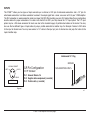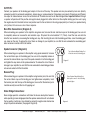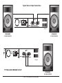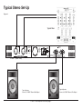
1
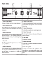
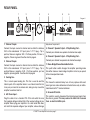
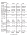
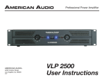
American Audio
®
User Instructions
™
American Audio®
4295 Charter Strret
Los Angeles Ca. 90058
Revised 5/01
CAUTION
Do not open risk of electric shock
CAUTION: TO REDUCE THE RISK OF ELECTRIC
SHOCK, DO NOT REMOVE THE COVER.
THERE ARE NO USER SERVICEABLE PARTS
INSIDE. REFER ALL SERVICE TO YOUR
AUTHORIZED AMERICAN AUDIO® DEALER.
The lightning flash with an arrow triangular
symbol is intended to alert the user to the
presence of non insulated “dangerous voltage” within the products enclosure, and
may be of sufficient magnitude to constitute
a risk of electric shock.
The exclamation point triangular symbol is
intended to alert the user to the presence
of important operating and maintenance
(servicing) instructions in the user manual
accompanying the CD player.
C
O
N
FOR OPTIMUM PERFORMANCE AND
RELIABILITY DO NOT PRESENT THE
AMPLIFIER WITH A SPEAKER LOAD
OF LESS THAN 2 OHMS. OR ANY
COMBINATION OF SPEAKERS THAT
TOGETHER ARE LESS THAN 2 OHMS!
POUR ASSURER LA FIABILETE ET
OBTENIT UNE PERFORMANCE OPTIMALE,
NESOUMETTE JAMAIS L’AMPLIFICATEUR
A UNE CHARGE D’IMPEDANCE TOTALE
INFERIEURE A 2 OHMS, NI AVEC UN H.P.
NI EN COMBINAISON DES H.P.
USING ONE SPEAKER, IT MUST BE AVEC UN H.P., IL FAUT UNE CHARGE
D’IMPEDANCE MINIMUM DE 2 OHMS.
RATED AT 4 OR MORE OHMS.
USING TWO SPEAKERS, THEY MUST AVEC DEUX H.P., FAUT POUR CHAOUN
RATED EACH AT 4 OR MORE OHMS. UNE CHARGE D’IMPEDANCE MINIMUM
DE 4 OHMS.
USING THREE SPEAKERS, THEY
MUST BE RATED EACH AT 8 OR AVEC TROIS H.P., FAUT POUR CHAOUN
UNE CHURGE D’IMPEDANCE MINIMUM
MORE OHMS.
DE 8 OHMS.
T
E
N
T
S
FRONT PANEL............................................................................................................................................................4
REAR PANEL..............................................................................................................................................................5
OPERATING VOLTAGE...............................................................................................................................................4
INPUTS........................................................................................................................................................................6
OUTPUTS....................................................................................................................................................................7
LIMITER......................................................................................................................................................................10
LOW-CUT FILTER......................................................................................................................................................11
FUSE..............................................................................................................................................................................5
LED INDICATORS.......................................................................................................................................................4
STEREO/BRIDGED MONO........................................................................................................................................10
PROTECTION............................................................................................................................................................10
V1500™ Power Amplifier Instructions page 2
Important Precautions
Introduction
1. Be sure to save the packing carton in case you may ever have
to return the unit for service.
2. Read all documentation before attempting to operate your
new amplifier. Please save all you documentation for future
reference.
3. Do not spill water or other liquids in to or on to your amplifier.
4. Be sure that the local power outlet match that or the required
voltage for your amplifier.
5. Do not attempt to operate this unit if the power cord has been
frayed or broken. Please route your power cord out of the way
of foot traffic.
6. Do not attempt to remove or break off the ground prong from
the electrical cord. This prong is used to reduce the risk of
electrical shock and fire in case of an internal short.
7. Always have the front gain controls set to their lowest level
during initial power-up to prevent speaker damage .
8. Disconnect from main power before making any type of
connection.
9. Do not block the units cooling vents or fan intake. If this unit is
being used in an extremely dusty or smoky environment, the
unit should be blown through on a regular basis.
10.Do not remove the top cover under any conditions. There are
no user serviceable parts inside.
11. Do not drive the inputs with a signal level greater than that
required to drive equipment to full output.
12. Do not try to run the input signal of an amplifier by the output of
any other amplifier.
13. Never ground a RED (positive) terminal. Never connect a RED
(hot) terminal to another RED (hot) terminal.
14. Disconnect the unit’s main power when left unused for long
periods of time.
Introduction: Congratulations and thank you for purchasing the
American Audio® V1500™ amplifier. This amplifier is a representation of American Audio’s continuing commitment to produce the best
and highest quality products all at an affordable price. This amplifier is an ultra-compact amplifier that packs a big punch! Please
read and understand this manual completely before attempting
to operate your new amplifier. This booklet contains important
information concerning the proper any safe operation of your new
amplifier.
Unpacking: Carefully open and unpack your amplifier. Be sure
to save the packaging in case you may ever need to return your
unit to the factory. After unpacking, inspect the amplifier for any
type of damage that may have occurred during shipping or transit.
If you notice any type of damage notify your dealer immediately
for instructions.
Installation: This amplifier is made to mount in a standard 19”
rack The front panel provides four holes used to screw the unit
into a rack The unit also provides a way to rear mount the unit
into a rack for added security. Rear mounting the unit is especially
recommended if the unit is to mounted in to a mobile rack.
Customer Support: American Audio® provides a toll free cus-
tomer support line, to provide set up help and to answer any question should you encounter problems during your set up or initial
operation. You may also visit us on the web at www.americandj.com
for any comments or suggestions. For service related issue please
contact American Audio ®. Service Hours are Monday through
Friday 9:00 a.m. to 5:00 p.m. Pacific Standard Time.
Voice:
(800) 322-6337
Fax:
(323) 582-2610
E-mail:
[email protected]
V1500™ Power Amplifier Instructions page 3
FRONT PANEL
1
11
1. Channel 1 Signal indicator -
2
5
4
3
6
7
Diagram 1
9
8
This Green LED will glow when there is an input signal present.
2. Channel 1 Protect indicator This red LED will glow when channel one goes in to protect mode.
In protect mode the output signal to the speakers will terminated
to channel one.
10
6. Channel 2 Protect indicator -
11
This red LED will glow when channel two goes in to protect mode.
In protect mode the output signal to the speakers will terminated
to channel two.
7. Channel 2 Signal indicator This Green LED will glow when there is an input signal present.
3. Channel 1 Clip indicator -
8. Channel 1 Gain control -
This LED comes on at the amplifiers clipping point, the point when
the output signal begins to distort. Under heavy clipping lower
the input gains (Diagram 8) to reduce the risk of damage to your
speakers and amplifier.
This knob adjust the channel one volume output to the speakers
connect to channel one.
4. Power LED This LED will glow when the amplifier is turned on, indicating
power is going to the unit.
9. Power Switch This switch turns the unit on.
10. Channel 2 Gain control This knob adjust the channel one volume output to the speakers
connect to channel one.
5. Channel 2 Clip indicator -
11. Exhaust Cooling Vents -
This LED comes on at the amplifiers clipping point, the point when
the output signal begins to distort. Under heavy clipping lower the
input gains (Diagram 10) to reduce the risk of damage to your
speakers and amplifier.
A cooling fan is mounted at rear of the amplifier. These exhaust
vents allow hot air to be pushed out of the amplified to allow
ample cooling of the internal components. Do Not Block These
Vents!
V1500™ Power Amplifier Instructions page 4
REAR PANEL
1
2
3
4
5
6
Diagram 2
7
8
9
1. Channel 1 Input -
may occur to your unit.
Connect the input source for channel one to either the balance
XLR or the unbalanced 1/4” input jacks. 1/4” TS plug - Tip is
positive, Sleeve is negative. XLR - Pin three positive, Pin two is
negative, Pin one is ground. See the chart on page 6.
5. Channel 1 Speaker Output - 5 Way Binding Post -
2. Channel 2 Input -
Connect your channel two speakers to channel two output.
Connect the input source for channel two to either the balance
XLR or the unbalanced 1/4” input jacks. 1/4” TS plug - Tip is
positive/Sleeve is negative. XLR - Pin three positive, pin two
negative, pin one ground. See the chart on page 6.
7. Mono-Bridge/Stereo Selectable Switch -
3. Cooling Fan -
8. Fuse -
This is a dual speed cooling fan. This fan is used to cool the
internal parts of the amplifier when in use. Never block the fan
in any way or mount in an enclose rack, doing so may cause the
amplifier to overheat and fail.
This house the external 8amp fuse. All way replace with exact
same type fuse unless otherwise instructed to do so by an authorized American DJ™ service technician.
4. A/C Power Input Plug this cable in to a standard 110~120v wall outlet. Be sure
that supplied voltage matches that of the required voltage of you
amplifier. Never plug your amplifier in to a wall outlet that does
not match the required voltage of your amplifier, serious damage
Connect your channel one speakers to channel one output.
6. Channel 2 Speaker Output - 5 Way Binding Post -
This push button switch changes the amplifier operating mode
from either stereo or mono bridge. Amplifiers arrive to you preset
in the stereo operation mode.
9. Ground Lift Switch This switch is used to disconnect the internal ground signal from
the chassis ground. This may reduce the buzz that is caused
from an electrical 60Hz cycle.
V1500™ Power Amplifier Instructions page 5
INPUTS
The V1500™ allows you two types of input connector per a channel, a XLR jack for balanced connections and a 1/4” jack for
unbalanced connections. Use these connection to connect the output signal from a mixer, cross-over or EQ to your V1500 amplifier.
The XLR connection is recommended for cable runs longer that 20ft. When building your own XLR cables follow the pin configuration
describe below for proper connections. For cable runs shorter than 20Ft. you may choose the 1/4” input option. The 1/4” input
option may be a little more convenient for most user due to the abundant supply of prefabricated cables on the market. You may
also use the two different types of input cables to jump a parallel connection to another amp. For Example: Connect a XLR cable
to the input of channel one. You may now connect a 1/4” cable to the input put jack of channel one and jump that cable to the
input of another amp.
Unbalanced 1/4” Plug
GROUND
XLR MALE SOCKET
HOT 3
1 EARTH
2 COLD
DATA IN
XLR Pin Configuration:
NON-INVERTING INPUT +
US ITT Standard
PIN 1: Ground / Return / 0v
PIN 2: Negative data complement (-,Inverted)
PIN 3: Positive data (+, inverted)
Diagram3
Diagram4
V1500™ Power Amplifier Instructions page 6
OUTPUTS:
Connect your speakers to the binding post outputs in the rear of the amp. The speaker wire may be connect by bare wire (directly
connected usually for permanent connections), banana plug, or spade connector. Connections are made to Channel one and Channel
two output for stereo mode or across the red terminals of Channels one and two for Mono Bridge Mode. Important Notice: Although
a speaker will operate with the positive and negative leads plugged into either terminal on the amplifier binding post, be sure to plug
the negative lead into the black terminal and positive lead into the red terminal. Ensuring proper polarity will avoid your speakers being
out of phase, that can cause a loss of bass response.
Bare WIre Connections: (Diagram 5)
When connecting your speakers to the amplifier using bare wire; Unscrew the red and black caps on the binding post, be sure not
to completely remove or unscrew the red and black caps. Strip back the wire insulation 1/2” (13mm). Insert the bare wire into the
hole that was reveled by unscrewing the binding post cap. After inserting the wire into the binding post hole, screw the binding post
cap down on the wire. To reduce the risk of shock or damage to your amplifier, be sure that the wire connected to one binding post
does not come in contact with that of another.
Spade Connector: (Diagram 6)
When connecting your speakers to the amplifier using spade connector; Unscrew
the red and black caps on the binding post, be sure not to completely remove or
unscrew the red and black caps. Insert the spade connector in to the binding post
and tighten the caps down on the spade connector. To reduce the risk of shock or
damage to your amplifier, be sure that the wire connected to one binding post does
not come in contact with that of another.
Typical Speaker Output Binding Post.
Insert bare wire into the binding post.
Diagram 5
Banana Plug:
When connecting your speakers to the amplifier using banana jacks; Be sure that
the red and black caps on the binding post are tighten down completely. Insert
the banana jacks into the caps of the binding post, be sure that the banana jack is
inserted securely to avoid the risk of it popping out.
Typical Speaker Output Binding Post.
Insert spade connector into the binding
post and tighten.
Mono Bridge Connections:
Mono bridge operation connections will follow the above descriptions however,
when operating in mono bridge operation the speaker connections will run between
the two positive (red) leads. Use channel two output for negative and channel one
output for positive connection. (See page 8 Diagram 8)
©American
DJ Supply® - www.americandj.com -
Diagram 6
V1500™ Power Amplifier Instructions page 7
Typical Stereo Output Connections
Diagram 7
SPEAKERS
4 OHM MINIMUM
SPEAKERS
4 OHM MINIMUM
Diagram 8
TYPICAL MONO BRIDGE SET-UP
SPEAKERS
8 OHM MINIMUM
V1500™ Power Amplifier Instructions page 8
Typical Stereo Set-Up
Diagram 9
Typical Mixer
V1500™ (Rear View)
Typical Speaker
Connect to V1500™ Channel One Output
V1500™ Power Amplifier Instructions page 9
Typical Speaker
Connect to V1500™ Channel Two Output
NORMAL OPERATION:
Page 9/Diagram9 show you an example of a typical stereo set-up. Connect your inputs into channels one and two of the amplifier.
Connect your speakers to the outputs on the rear of the amplifier. Be sure that your front gain controls are turned down to their lowest
level (full counter-clockwise). Turn your amp on. Turn your input level up. Use your front gain controls to regulate the output volume. Be
sure not to raise the volume to the clip level however, an intermittent clip signal is acceptable.
MONO BRIDGE OPERATION:
Page 8/Diagram 8 give you a description of mono bridge set-up. Be sure you amplifier and all other equipment is shut off. Press
the Stereo/Mono switch to the in position (Page 5/Diagram 2 #7). Connect an input signal to channel one. Connect your speaker
across the red output binding post on the rear of your amplifier (See Page 7 Mono Bridge Set-Up). Turn your equipment on (your
amplifier should be the last piece you turn on). Apply an input signal to your amplifier. Turn channel two gain up. Use the channel
one gain to regulate your amplifier output.
PROTECTION:
LIMITER
During normal operation, the limiter does not affect the audio signal and is, in fact inaudible. It will allow brief clipping of peaks and
will only activate when continuous,hard clipping occurs. The limiter will then reduce the audio signal enough to minimize the amount of
clipping. When the signal amplitude decreases enough that clipping ends, the limiter will deactivate and cease its gain reduction.
SHORT CIRCUIT PROTECTION
The Output Short circuit protects the output devices from short circuits and stressful loads.
THERMAL PROTECTION
A single variable-speed fan provides adequate cooling. But if the heatsink temperature exceeds 90C., the amplifier will mute until
the amplifier cools down.
INPUT/OUTPUT PROTECTION
The input circuits are isolated by 10k resistors. An ultrasonic network decouples RF from the output and helps keep the amplifier
stable with reactive loads.
V1500™ Power Amplifier Instructions page 10
SPECIFICATIONS
MODEL NO:
Output Power:
2 ohms, 1 khz 1% THD
4 ohms, 1khz, 1%THD
8 ohms, 1khz 1% THD
(Bridge Mode, mono)
4 ohms, 1khz, 1% THD
8 ohms, 1khz, 1% THD
V-1500
V-2000 MKII
V-3000
V-4000
N/A
280W RMS PER CH.
200W RMS PER CH.
540W RMS PER CH.
400W RMS PER CH.
280W RMS PER CH.
800W RMS PER CH.
600W RMS PER CH.
360W RMS PER CH.
1400W RMS PER CH.
1010W RMS PER CH.
600W RMS PER CH.
N/A
600 WATTS RMS
1050 WATTS RMS
820 WATTS RMS
1500 WATTS RMS
1100 WATTS RMS
2500 WATTS RMS
1650 WATTS RMS
Total Harmonic Distortion:
20Hz-20kHz, @ rated
Less than 0.1%
output power, 8 ohms
Less than 0.1%
Less than 0.1%
Less than 0.02%
Input Sensitivity and
Impedance: @ rated
output power, 8 ohms
1.0v RMS (0 dBv)
1.0v RMS (0 dBv)
1.0v RMS (0 dBv)
1.75” (4.4cm)
19 ” (48.3cm)
15.25” (40cm)
25 lbs. (10.5kg)
3.5 ” (8.8cm)
19 ” (48.3cm)
15.9” (40.5cm)
30 lbs. (13.6kg)
3.5” (8.8cm)
19 ” (48.3cm)
15.9” (40.5cm)
31 lbs. (14 kg.)
10 Hz - 40 kHz
10 Hz - 40 kHz
10 Hz- 40 kHz
10 Hz- 40 kHz
20 Hz- 20 kHz
20 Hz - 20 kHz
20 Hz- 40 kHz
20 Hz- 40 kHz
100 dB, unweighted
100 dB, unweighted
100 dB, unweighted
100 dB, unweighted
Dimensions & Weight:
Height
Width
Depth
Weight
Frequency Response:
+/- 1db, 1w RMS. 8 ohms
+/- 0.2 db, @ rated output,
8 ohms
Hum & Noise:
Below rated output, 8 ohms
Power Consumption: @
rated output power, 8 ohms
Cooling System:
1.5v rms
8A @ 120v AC
7A @ 120vAC
1 Dual Speed Fan
and Heatsinks
2 Dual Speed Fans
and Heatsinks
10A @ 120vAC
2 Dual Speed Fans
and Heatsinks
V1500™ Power Amplifier Instructions page 11
5.25” (13.3cm)
19 ” (48.3cm)
15.9” (40.5cm)
61.7 lbs. (28 kg.)
40A @ 120vAC
2 Dual Speed Fans
and Heatsinks
©American Audio
American DJ Group of Companies World Headquarters:
4295 Charter Street Los Angeles, CA 90058 USA
Tel: 323-582-2650 / Fax: 323-582-2610
web: www.americandj.com / e-mail: [email protected]