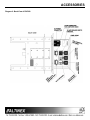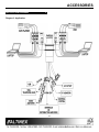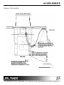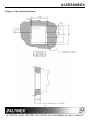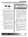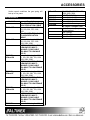
1
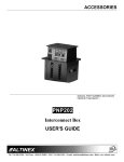
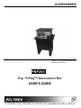
ACCESSORIES
MANUAL PART NUMBER: 400-0057-003
PRODUCT REVISION: 3
PNP200 P
Pop ‘N Plug™ Interconnect Box
USER'S GUIDE
_________
USER’S GUIDE
ACCESSORIES
INTRODUCTION
TABLE OF CONTENTS
Page
Your purchase of the PNP200 Interconnect Box is
greatly appreciated. We are sure you will find it
reliable and simple to use.
PRECAUTIONS / SAFETY WARNINGS .................
GENERAL ..........................................................2
Superior performance for the right price, backed by
solid technical and customer support is what
Altinex has to offer.
INSTALLATION..................................................2
CLEANING .........................................................2
FCC / CE NOTICE .............................................2
The product you are holding in your hands is
designed using state-of-the-art technology and is
superior to anything available on the market. You
will find this and our other products reliable, long
lasting, and simple to operate.
ABOUT YOUR PNP200.........................................3
TECHNICAL SPECIFICATIONS............................3
PNP200 DIMENSIONS..........................................4
DIAGRAM 1........................................................4
We are committed to providing our customers with
signal management solutions to the most
demanding audio-visual installations at very
competitive pricing.
DIAGRAM 2........................................................5
APPLICATION DIAGRAM .......................................
DIAGRAM 3........................................................6
We appreciate your selection of our products and
are confident that you will join the ranks of our
many satisfied customers throughout the world.
DIAGRAM 4........................................................7
DIAGRAM 5........................................................8
INSTALLATION .....................................................9
OPERATION .......................................................10
This manual covers:
LOCK, RELEASE, AND STATUS
CONTROL PIN.................................................10
PNP200 – Pop `N Plug™ Interconnect Box.
HOW TO RELEASE AND REPLACE THE
GAS SPRING...................................................10
ACCESSORIES...................................................11
TROUBLESHOOTING GUIDE ............................12
ALTINEX POLICY ...............................................12
LIMITED WARRANTY......................................12
RETURN POLICY ............................................12
CONTACT INFORMATION ..............................12
1
1
ACCESSORIES
PRECAUTIONS / SAFETY WARNINGS
•
1
Please read this manual carefully before using your
PNP200 Interconnect Box. Keep this manual handy
for future reference. These safety instructions are
to ensure the long life of your PNP200 and to
prevent fire and shock hazard. Please read them
carefully and heed all warnings.
•
1.3 CLEANING
1.1 GENERAL
•
•
•
Unauthorized personnel shall not open the unit
since there are high-voltage components
inside.
Qualified Altinex service personnel, or their
authorized representatives must perform all
service.
•
•
•
•
•
Surfaces should be cleaned with a dry cloth.
Never use strong detergents or solvents, such
as alcohol or thinner. Do not use a wet cloth or
water to clean the unit.
1.4 FCC / CE NOTICE
•
1.2 INSTALLATION
•
We recommend using wall outlets with a
Ground Fault Circuit Interrupter (GFCI) for
maximum protection.
Install all cables according to the instructions.
Do not force or pull out any cable or power
cord that is attached to the PNP200
Interconnect Box.
For best results, place the PNP200
Interconnect Box in a dry area away from dust
and moisture.
To prevent fire or shock, do not expose this
unit to rain or moisture. Do not place the
PNP200 Interconnect Box in direct sunlight,
near heaters or heat radiating appliances, or
near any liquid. Exposure to direct sunlight,
smoke, or steam can harm internal
components.
Handle the PNP200 Interconnect Box
carefully. Dropping or jarring can damage
internal components.
Never place fingers inside the openings in the
back of the unit. This action could cause
serious injury because of the sharp edges
inside of the PNP200.
Do not place heavy objects on top of the
PNP200. Do not use excessive force to push
down on the top of the unit.
To turn off main power, disconnect the power
cord, which powers the power socket on the
PNP200 pop-up panels only, and unplug the
9V 500mA-power supply. The power outlet
socket should be installed as near to the
equipment as possible, and should be easily
accessible.
•
•
2
2
This device complies with part 15 of the FCC
Rules. Operation is subject to the following two
conditions: (1) This device may not cause
harmful interference, and (2) this device must
accept any interference received, including
that which may cause undesired operation.
This equipment has been tested and found to
comply with the limits for a Class A digital
device, pursuant, to Part 15 of the FCC Rules.
These limits are designed to provide
reasonable
protection
against
harmful
interference when the equipment is operated
in a commercial environment. This equipment
generates, uses, and can radiate radio
frequency energy and, if not installed and used
in accordance with the instruction manual, may
cause
harmful
interference
to
radio
communications. Operation of this equipment
in a residential area is likely to cause harmful
interference in which case the user will be
required to correct the interference at his own
expense.
Any changes or modifications to the unit not
expressly approved by Altinex, Inc. could void
the user’s authority to operate the equipment.
ACCESSORIES
ABOUT YOUR PNP200
2
TECHNICAL SPECIFICATIONS
The PNP200 is designed for installation into a
conference room table. The Pop ‘N Plug™
Interconnect Box (PNP200) provides a means of
connecting audio, video, control, and computer
video sources into a presentation system. It is ideal
for use together with Altinex computer video
interfaces. The Pop ‘N Plug™ Interconnect Box can
either “pop up” into a raised position to provide
access to connectors or it can be lowered into a
table when not in use. Using a tower-type
construction with pneumatic suspension and an
electromagnetic latching mechanism does this.
3
FEATURES/DESCRIPTION
PNP200
GENERAL
Front Panel Standard
Configuration Connectors
(side without fuse box)
Power
1 IEC (standard)
Computer Video
1 15-pin HD-F
Composite Video
1 Yellow RCA F
Audio, left, right
1 Black, 1 Red RCA F
Audio
1 3.5 mm stereo F
Telephone
1-RJ-11 F (6-position)
Network
1 RJ-45 F (8-position)
Control
1 DB-9 F
The Pop ‘N Plug™ Interconnect Box provides easy
access to system inputs when they are needed. It
also removes system inputs when not needed,
eliminating the obstruction. The Pop ‘N Plug™
Interconnect Box has two input plates on either side
of the unit, servicing both sides of a table. Each
standard plate offers Computer Video (15-pin HD);
Composite Video (RCA), Audio (RCA), Computer
Audio (Stereo Mini), Modem (RJ-11), 9-pin D-type
RS-232 and Network (RJ-45) input connections. All
signals are passed through to a set of female
connectors or cables. Several optional connectors
can be substituted for the standard set of
connectors.
Back Panel Standard Configuration Connectors
(side with fuse box )
Power
1 IEC with 10 A fuse
Computer Video
1 15-pin HD-F
Composite Video
1 Yellow RCA
Audio, left, right
1 Black, 1 Red RCA
Audio
1 3.5 mm stereo
Telephone
1-RJ-11
Network
1 RJ-45
Control
1 DB-9 F
Table 1. PNP200 General
MECHANICAL
PNP200
Mechanical
Width (inches)
6.030in (153mm)
Height (inches)
8.230in (209mm)
Finish
Black
T° Operating
10°C-35°C
T° Maximum
50°C
Humidity
90% non-condensing
Table 2. PNP200 Mechanical
The Pop ‘N Plug™ Interconnect Box is designed for
use with tables ranging from one to three inches
thick. It offers an adjustable retaining ring to secure
the unit flush with the table’s surface. The Pop ‘N
Plug™ comes in a standard matte black color. The
top of the unit can be finished to match the table or
it can be painted another color. This is available on
the custom per order basis at an additional charge.
Power
Power for Operation
Power Consumption
Power Rating (pass through
connector)
Table 3. PNP200 Electrical
3
3
9V 500mA DC
Max 10 watts
90-140 VAC, 2A Max
ACCESSORIES
PNP200 DIMENSIONS
4
Diagrams: 1A, 1B, 1C, & 1D
PNP200 DIMENSIONS *(con’t)
Diagram 2: Back View
4
4
ACCESSORIES
Diagram 2: Back View of PNP200
5
5
ACCESSORIES
APPLICATION DIAGRAM
5
Diagram 3: Application
6
6
ACCESSORIES
Diagram 4: Final Installation
7
7
ACCESSORIES
Diagram 5: Table Cutout Requirements
8
8
ACCESSORIES
INSTALLATION
6
Step 1. Make sure the gas spring is not
compressed when you remove the locking
screw. To release the gas spring, push
down and turn the knob in the center of
the bottom of the PNP200 by 90 degrees.
Remove the lock down screw from the
PNP200. The locking screw is the
smallest silver colored screw that is
located on the bottom of the unit. Reengage the gas spring by pushing down
on the knob and turning it back to the
original position, thereby locking the gas
spring into place.
Figure 2: Support Plate
Step 4. Insert the PNP200 into the table. The
PNP200 can be adjusted to be flush or at
exactly the same level as the tabletop.
Turning the four-socket head set screws
on the top of the PNP200 does this. An
allen wrench provided with the PNP200 is
used to adjust the height level.
Step 5.Insert the four screws, which are provided,
into the adjustable retaining ring from
bottom side of the table. The adjustable
retaining ring allows securing unit to the
table. The adjustable retaining ring is a flat
square plate with two bent edges, that will
not fit into the hole in the table.
Figure 1: Gas Spring
Step 2. Cut an opening into the table’s surface
using the dimensions of 7.38 in x 6.05in.
Refer to diagram 5 on page 7 of the
manual for table cutout requirements.
Note: The table can be 3 inches or thinner
in thickness. Always confirm dimensions
before cutting to insure that specifications
have not changed.
Step 3. Place the support plate into the hole in the
table. The support plate is the square flat
plate that can fit into the hole in the table
(See Figure 2).
Figure 3: Insertion of Screws into the Adjustable
Retaining Ring
Step 6. Secure the cables by using the provided
mounting brackets. There are two
mounting brackets (See Figure 4). Pass
the power cord from the side of the
housing and attach it to the surface with
the cable-clamp supplied with the PNP200
9
9
ACCESSORIES
unit. Do not keep the cord too tight or too
loose (See Diagram 4, page 6).
CONGRATULATIONS! YOU ARE DONE.
ENJOY YOUR Pop `N Plug™ Interconnect Box.
If you experience any problems, please call
1-800-258-4623 or 1-714-990-2300 for
international calls.
OPERATION
7
Figure 4: Mounting Brackets
7.1 LOCK, RELEASE, STATUS CONTROL PINS
Step 7. Make that the provided ground wire
assembly is secured to the threaded nut
located on the bottom of the housing of the
PNP200 with a star-washer and a 4-40
screw as shown in Diagram 4, page 6.
To lock the position of the PNP200, connect
the LOCK pin of the terminal block to GND.
Note: the power supply is rated at 9V, but
since the current demand of the PNP200 is
low, it will reach 12 volts at the terminal block.
If a regulated power supply is used, it should
be a 12-volt power supply. A regulated power
supply is when the power supply is at 12 volts,
and when the power supply is at 9 volts, it is
known as unregulated.
Step 8.Attach the other end of the ground wire
assembly to a Protective Earth Ground
with provided 6-32 screw and star-washer.
Step 9.Connect the appropriate cables with the
correct input connectors. There are two
RCA connectors on each side of the
PNP200. The black connectors are known
as audio left, whereas the red connectors
are called audio right. On either side of the
unit, there is also a RCA video connector,
which is yellow in color. The network
connection is red; In addition, the
telephone or data connection is gray.
To release the top connector assembly,
connect the RELEASE pin of the terminal
block to GND.
To determine the status of the PNP200,
examine the STATUS pin. The status pin
should be a TTL digital level only. When the
PNP200 is in an up position 5 volts is present,
whereas 0 volts represents the down position.
Step 10. Once you have applied power and
connected the proper cables on the
bottom of the unit, you may raise the unit.
To raise the PNP200 into position, press
the top of the unit.
7.2 HOW TO RELEASE AND REPLACE THE GAS
SPRING
To replace the spring, push up, and turn the
knob in the center on the bottom of the
PNP200 by 90 degrees, thereby releasing the
gas spring.
Step 11. To lower the unit, push on the top of the
PNP200 until it fits into place. When the
9V DC adapter is plugged in, 9 volts must
be applied. Once the 9 volts have been
applied, the release top connection will be
engaged. This mechanism allows the unit
to lock into place, and then pop up when
pressure is put on the top of the unit.
Unscrew the knob, and then unscrew the gas
spring itself from the PNP200. Replace the
gas spring with a new one by screwing it in,
and then replacing the knob.
Re-engage the new gas spring by pushing up,
and turning the knob by 90 degrees. After you
have finished this step, you have completed
the installation.
10
10
ACCESSORIES
Under normal conditions the gas spring will
last up to five years.
ACCESSORIES
Model No.
CB37xxMR
CB39xxMR
CB5000PL5VMxxxVM
CB5000PL5VMxxxVF
CB5100PL5VMxxxVM
CB5100PL-
5VMxxxVF
8
PC5301US
PC5302UK
PC5303AU
PC5304GR
Description
VGA MALE TO MALE (HD-15)
HIGH RESOLUTION CABLE
xx = available length of 3ft, 6ft,
15ft, 25ft, 50ft, 75ft, 100ft,
150ft
VGA MALE TO FEMALE (HD15) HIGH RESOLUTION
CABLE
xx = available length of 3ft, 6ft,
15ft, 25ft, 50ft, 75ft, 100ft,
150ft, 200ft, 250ft
SUPER HIGH RESOLUTION
PLENUM-FLEX MULTICHANNEL COAX CABLE
VGA MALE TO VGA MALE
(HD-15)
xxx = available length of 3ft,
6ft, 15ft, 25ft, 50ft, 75ft, 100ft,
150ft, 200ft, 250ft
SUPER HIGH RESOLUTION
PLENUM-FLEX MULTICHANNEL COAX CABLE
VGA MALE TO VGA FEMALE
(HD-15)
xxx = available length of 3ft,
6ft, 15ft, 25ft, 50ft, 75ft, 100ft,
150ft, 200ft, 250ft
SUPER HIGH RESOLUTION
PLENUM-FLEX MULTICHANNEL COAX CABLE
VGA MALE TO VGA FEMALE
(HD-15)
xxx = available length of 3ft,
6ft, 15ft, 25ft, 50ft, 75ft, 100ft,
150ft, 200ft, 250ft
SUPER HIGH RESOLUTION
PLENUM-FLEX MULTICHANNEL COAX CABLE
VGA MALE TO VGA FEMALE
(HD-15)
xxx = available length of 3ft,
11
11
6ft, 15ft, 25ft, 50ft, 75ft, 100ft,
150ft, 200ft, 250ft
POWER CABLES
Power Cable for US
Power Cable for UK
Power Cable Australia
Power Cable Germany
OPTIONAL CONNECTORS
Blank Connector (Snap-in and
15-pin location)
BNC Female
4-pin Mini-DIN
6-pin Mini-DIN
ACCESSORIES
9
that an Altinex product needs to be returned
please follow the policies below:
The PNP200 supplied unit was carefully tested and
no problems were detected; however, we would
like to offer these suggestions.
Altinex will accept all product returns for a period
of 30 days from authorized Altinex dealers in an
unopened package.
•
Please make sure that the Fuse is of a 10
Amps rating.
•
Please make sure that the highest quality
video, audio, network, and telephone cables or
connectors are used.
If a product has been opened, the restocking fees
will apply. For the restocking fee, please contact
an Altinex Sales Representative.
TROUBLESHOOTING GUIDE
•
Make sure that the 9V DC adapter or the
external regulated 12 volts is plugged into the
power.socket for proper operation.
•
Make sure that any cable or power cord is not
damaged or pinched. If it has been damaged,
then do not use the PNP200 unit. Immediately
contact the Altinex Customer Service
Department to have
ALTINEX POLICY
If the product is in your possession for more than
30 days, the restocking fees will apply.
Altinex will not accept any returns on cables or
custom products.
If your product is in warranty and needs service,
contact the Altinex Sales Department for an RMA
(Return Material Authorization). Products returned
without an RMA number may experience a delay
in service.
If your product is out of warranty and needs
service, contact the Altinex Sales Department for
an RMA (Return Material Authorization). Products
returned without an RMA number may experience
a delay in service. The service charges will be
quoted to you before the actual repairs are done.
10
10.1 LIMITED WARRANTY
Altinex warrants that its products and cables are
free from defects in materials under normal use
and service. This warranty is limited to repairing at
company’s factory any part or parts of the product
that shall within 2 years (90 days for cables) from
date of shipment to the purchaser be returned to
company with transportation charges pre-paid.
The company’s examination shall disclose
product(s) to be thus defective. The warranty is
expressly in lieu of all other warranties expressed
or implied. Altinex neither assumes nor authorizes
any other person to assume for it any other liability
concerning the sale of the products. This warranty
shall not apply to any product that shall have been
repaired or altered outside of company’s factory in
any way so as, in its judgment, to affect its
stability or reliability, or that has been subject to
misuse, negligence or accident.
10.3 CONTACT INFORMATION
Sales Department
Phone:
Fax:
714-990-2300
714-990-3303
Accounting Department
Phone:
Fax:
10.2 RETURN POLICY
It is very important to Altinex that you receive all
products that you have ordered and that this
product fulfills your needs. In the unlikely event,
12
12
714-990-6088
714-990-5778