1
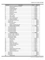
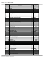
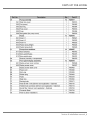
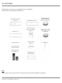
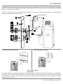
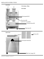
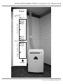
PORTABLE AIR CONDITIONER
M00019-V01
CAUTION
This symbol denotes a caution or warning.
Caution:
- Please read these instructions carefully before installing and operating your Williamson-Thermoflo portable air
conditioner. They will help you to derive the maximum benefit from your air conditioner.
- The air conditioner should always be operated or stored in an upright position. If you have any reason to
believe that it was not always in an upright position during the 24 hours before you acquired it, leave it
upright for 24 hours before attempting to operate it. This will help to ensure that your air conditioner will run
properly.
Service & installation manual
CONTENTS
Introduction
1
Technical specifications
2
Disassembly illustration
3
Parts list per model
Accessories
Installation instructions
4-6
7
8-11
Service & installation manual
INTRODUCTION
For future reference, we suggest you attach a copy of your sales slip/receipt to this page, along with the following
information which is located on the manufacturer’s nameplate located on the side of the unit. You will be asked this information if your unit requires servicing and/or for general inquiries.
Model number:
Serial number:
Date of purchase:
Date of installation:
Dealer’s Name and Address:
Service & installation manual _1
TECHNICAL SPECIFICATIONS
Service & installation manual _2
See Installation instructions p.8
DISASSEMBLY ILLUSTRATION
Service & installation manual _3
PARTS LIST PER MODEL
Service & installation manual _4
PARTS LIST PER MODEL
Ref. No.
30
31
33
35
36
37
38
39
40
41
42
42-1
42-2
43
44
44-1
44-2
45
47
48
48-1
48-2
48-3
49
49-1
49-2
50
51
52
53-1
53-2
54
54-1
54-2
54-3
54-4
54-5
55
55-1
55-2
56
56-1
56-2
Description
Seal gasket
White rubber holder
Stopper
Fixed louvers air intake
Remote control & holder
Front panel
Screw cap cover
back panel
back panel door
Insulation material (Compressor)
Evaporator fan motor assembly
Evaporator fan motor
Motor cushion
PCB (display screen)
Condenser fan motor assembly
Condenser fan motor
Motor cushion
Casing set
Flow control bar
Axis of rotation assembly
Axis of rotation 1
Axis of rotation 2
Axis of rotation rod
Step motor assembly
Step motor
Step motor installation board
Grid
Case assembly (bottom)
Evaporator assembly
Control box assembly
Control box
Control box cover
Electrical Parts assembly
PCB
Transformer
Capacitor 8.0uf/250vac
Capacitor 45uf/250vac
Relay
Air outlet assembly
Air outlet (front)
Air outlet (back)
Air outlet connectors
Upper air outlet connector
Lower air outlet connector
Service & installation manual _5
Qty
Part N°
4
4
2
1
1
1
2
1
1
1
Kit
1
2
1
Kit
1
2
1
2
Kit
1
1
1
Kit
1
1
1
1
1
Kit
1
1
Kit
1
1
1
1
1
Kit
1
1
P00421
P00422
P00423
P00425
P00500
P00501
P00428
P00502
P00430
P00431
K00073
P00503
P00504
P00505
K00074
P00506
P00507
P00508
P00441
K00059
P00442
P00443
P00444
K00060
P00445
P00446
P00509
P00510
P00511
K00061
P00450
P00451
K00110
P00512
P00513
P00454
P00455
P00514
K00063
P00457
P00458
K00064
P00459
P00460
1
1
PARTS LIST PER MODEL
Service & installation manual _6
ACCESSORIES
The following accessories are supplied with the air conditioner.
*The quantities are indicated in parentheses.
26. Window panel with
2 holes A (1)
27. Window panel B (1)
78. Panel C (1)
Owner’s manual (1)
Service & installation
manual (1)
30. Seal gasket (2)
31. White rubber
holder (2)
36. Remote control
and holder (1)
29. (28,1-28,2-28,3)
Window flange with
flaps for air exhaust (1)
29. (35) Window flange
with fixed louvers for
air intake (1)
33. Stopper (2)
AAA batteries for
remote control (2)
Note:
Please check accessories to make sure that you have all the parts needed for installation.
Service & installation manual _7
ACCESSORIES
1. Slide the outside window flanges through the holes in the window panel. Then, from the inside, place the rubber
gaskets on the ends of the flanges, snugly against the window panel. Then, screw the lock rings onto the corresponding
flanges, as shown on the illustration.
2. There is a small black hose for water drainage inside the air exhaust hose. The black hose must be passed through the
window flange to drain the water outside.
Drain hose
33
27
23
B
A
28-1
26
28-2
30
Air exhaust
28-3
35
22
24
29
35
31
Air intake
Horizontal window installation
Vertical window installation
A
B
B
A
A: Air exhaust - Warm
B: Air intake
The flange with flaps is designed to connect to the exhaust hose. The other flange (with fixed louvers) is designed to
connect to the air-intake hose. If the adapter is installed vertically, the flange for the exhaust hose must be placed above
the flange for the air-intake hose. This will prevent the air-intake hose from absorbing the hot and humid air expelled
through the exhaust hose.
Service & installation manual _8
INSTALLATION INSTRUCTIONS
BACK VIEW
A
B
A: Air exhaust - Warm
B: Air intake
Draining tube (#60-3)
Direct drain (#68)
(garden hose not included)
Back panel door (#40)
Wheel back (#7)
FRONT VIEW
Air filters (#10)
Control panel button (#65)
Wheel front (stopper) (#6)
Service & installation manual _9
INSTALLATION INSTRUCTIONS (Computer room application)
Already assembled
Optional
Already mounted on the unit
Optional
Portable
Service & installation manual _10
INSTALLATION INSTRUCTIONS (Computer room application)
Direct drain (garden hose not included)
Round filter (# 76)
Optional
Remove the back panel (# 40)
Power cord (# 67)
Draining tube (# 60-3)
Service & installation manual _11
8201 W. Calumet Road, Milwaukee, WI 53223 USA
www.williamson-thermoflo.com