1
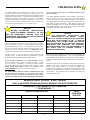
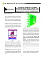
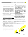
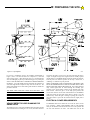
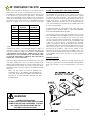
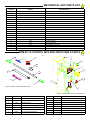
INSTALLATION AND
OWNER’S MANUAL
HDSWG 1000
Heavy Duty Commercial
Vehicular Swing Gate Operator
104950
READ THIS MANUAL
Serial #:
Date Installed:
As of date of manufacture,
meets all ANSI/UL 325
Safety Requirements for
Vehicular gate operators
CAREFULLY BEFORE
Your Dealer:
INSTALLATION OR USE
1
TABLE OF
Pre-Installation Notes ............................................................................ 3
Section A: Installation Notes ................................................................ 4
Section B: Preparing the Site ............................................................... 6
The Concrete Operator Pad ....................................................... 6
Placing the Vehicle Detector Loops ......................................... 6
Electrical Power Requirements ................................................. 8
Section C: Installing the Operator ....................................................... 9
Placing the Mechanical Unit .................................................... 10
Installing the Arm ..................................................................... 10
Installing the Control Box ........................................................ 11
Electrical Hookup ..................................................................... 11
Connecting the Mechanical Unit to the Control Box .............. 12
Bi-Parting Wiring Diagrams ..................................................... 13
Accessory Equipment Hookup ................................................ 15
Wiring Diagram ......................................................................... 13
Terminal Strip Reference Chart ............................................... 18
Section D: Starting the Operator........................................................ 19
Setting the Limit Switches ....................................................... 19
Pre-Setting the Motor Overload Sensitivity ............................ 19
Setting the Switch Selectable Options.................................... 19
Applying Power ........................................................................ 20
Maximum Run Timer ................................................................ 22
Final Settings ............................................................................ 22
Section E: Auxiliary Equipment ......................................................... 20
Section F: Safety Guide ...................................................................... 21
Operator Exploded View & Parts List ................................................. 23
Technical Specifications ..................................................................... 24
READ THESE STATEMENTS CAREFULLY AND FOLLOW THE
INSTRUCTIONS CLOSELY.
The Warning and Caution boxes throughout this manual are there to protect you and
your equipment. Pay close attention to these boxes as you follow the manual.
WARNING
CAUTION
WARNING
CAUTION
Indicates a MECHANICAL
hazard of INJURY OR
DEATH. Gives instructions
to avoid the hazard.
Indicates a MECHANICAL hazard
of DAMAGE to your gate, gate
operator, or equipment. Gives
instructions to avoid the hazard.
Indicates an ELECTRICAL
hazard of INJURY OR
DEATH. Gives instructions
to avoid the hazard.
Indicates an ELECTRICAL hazard
of DAMAGE to your gate, gate
operator, or equipment. Gives
instructions to avoid the hazard.
2
PRE-INSTALLATION
The Allstar HDSWG 1000 Vehicular Gate Operator will provide
convenience and assurance to the ultimate users for many years. It is
ruggedly built of the finest materials and has been thoroughly inspected
and tested at the Allstar factory. It has many features that will aid in the
installation and testing of the complete gate system. The HDSWG
1000 has been evaluated by Underwriters Laboratory, Inc. (UL) and is
certified to comply with UL Standard for Safety 325, as evidenced by
the UL symbol on the name plate. (115 Volt version only.)
sensors, protective screen mesh, etc) to eliminate hazards in your
gate system design.
* The Allstar HDSWG 1000 built-in overload detector will activate if
there is an abrupt increase in motor current above that normally
required to move the gate. THE OVERLOAD DETECTION POINT IS
AN ADJUSTABLE SETTING THAT MUST BE DETERMINED AT
THE TIME OF INSTALLATION. THIS SETTING MUST BE
TESTED PERIODICALLY TO ENSURE PROPER OPERATION.
THE MORE FREELY THE GATE WILL MOVE THE MORE
SENSITIVE THIS SETTING CAN BE MADE.
NOTICE
BEFORE
ATTEMPTING
INSTALLATION,
READ THIS MANUAL CAREFULLY SO YOU
WILL BE THOROUGHLY FAMILIAR WITH THE
FEATURES OF THE HDSWG 1000 AND ITS PROPER
INSTALLATION PROCEDURES.
NOTICE
THE
IMPORTANT
SAFEGUARDS
AND
INSTRUCTIONS IN THIS MANUAL
CANNOT
COVER ALL POSSIBLE CONDITIONS AND SITUATIONS
WHICH MAY OCCUR DURING ITS USE. IT MUST BE
UNDERSTOOD THAT COMMON SENSE AND CAUTION
MUST BE EXERCISED BY THE PERSON(S) INSTALLING,
MAINTAINING AND OPERATING THE EQUIPMENT
DESCRIBED HEREIN. DO NOT USE THIS EQUIPMENT FOR
ANY OTHER THAN ITS INTENDED PURPOSE —
OPERATING A SWING GATE.
Because the Allstar HDSWG 1000 (as well as gate operators sold by
other manufactures) is designed to start and move gates weighing as
much as 1200 pounds, or more,---the Allstar HDSWG 1000 is capable
of producing high levels of force. It is important in the design of the
total gate system that designers, installers and users be aware of the
hazards that may be associated with the IMPROPER design,
installation and use of Vehicular Gate systems and Gate Operators.
The gate operator is only one part of a complete automatic gate
operating system. As each location and usage is different, a properly
designed system will include all applicable safety devices.
ADVISE THE PURCHASER TO CHECK THE SENSITIVITY OF
THE OVERLOAD PERIODICALLY AND, AFTER REMOVING
THE CONTROL BOX COVER, LOG THE DATE TESTED ON THE
LOG DECAL PROVIDED ON THE CONTROL BOX (See Figure 1,
below.)
As the designer and installer of the GATE SYSTEM, you must
advise the purchaser on the proper use of the gate system. You also
have the primary responsibility of insuring that ALL possible
operational hazards have been considered and eliminated. YOU
MUST ADVISE AND WARN the purchaser and the ultimate user of
ANY HAZARDS that you have not been able to eliminate.
The HDSWG 1000 is also provided with a Torque Limiter that may be
adjusted to "slip" when an obstruction is encountered. However, the
purpose of the Torque Limiter is to protect the HDSWG 1000
mechanical parts. Whether the overload is activated before the Torque
Limiter slips will depend upon the "tightness" of the adjustment of the
Torque Limiter. This adjustment will be explained in the final check
out of the HDSWG 1000.
The Allstar HDSWG 1000 has a built-in "overload detector" that
can help reduce the hazards of your gate system. This device,
however, must not be considered as the primary defense system.
Consider all available options (electric leading edges, photoelectric
W A R N I N G H I G H V O LTA G E
ONLY A QUALIFIED TECHNICIAN SHOULD SERVICE THIS GATE OPERATOR
PERIODICALLY TEST SENSITIVITY OF OVERLOAD
*** READ MANUAL ***
LOG DATE OVERLOAD TEST
DATE TESTED
DATE TESTED
DATE TESTED
3
DATE TESTED
DATES
OPERATOR
SERVICED
Figure 1
A: IMPORTANT INSTALLATION NOTES
WARNING!
TO REDUCE THE RISK OF SEVERE
INJURY OR DEATH: READ AND FOLLOW
ALL INSTALLATION INSTRUCTIONS AND
GATE SYSTEM DESIGN PARAMETERS!
GATE SYSTEM DESIGN AND INSTALLATION
SAFETY CHECK LIST:
104949
• DO NOT locate any device (key switch, switch, key pad, card
reader, etc.) in a position where it may be activated by a person
reaching through the gate or while touching the gate in any
manner.
• Install all devices that will open or close the gate in such a
manner that THE GATE WILL BE IN FULL VIEW WHEN
THE DEVICE IS OPERATED. The recommended distance
between gate or fence and accessory is 10 feet.
• SECURELY ATTACH THE WARNING SIGNS provided
with the HDSWG 1000 on the gate (one on the outside and one
on the inside) where they can be seen by persons in the area of
the gate to alert them of automatic gate operation. (If the user
refuses to have the warning signs installed, Allstar
recommends that you note this on your records and have the
user sign a disclaimer.) See Figurez2.
Figure 3
•
The Allstar HDSWG 1000 is a VEHICULAR GATE
OPERATOR and as such is NOT RECOMMENDED FOR
PEDESTRIAN traffic. In installations where pedestrians are
likely to be nearby, install a pedestrian gate and use leading
edge detectors and/or photocells in your design to protect
system entrapment zones. Allstar can provide these products
for incorporation in your gate installation.
• SWING GATES HAVE THE POTENTIAL HAZARD OF
HANDS AND FINGERS BEING PINCHED between the gate
edge and the post to which the gate is mounted. It is
recommended that the hinges be mounted so that this opening
increases as the gate swings open.
PROTECT THIS
"PINCH POINT" SO THIS HAZARD IS AVERTED. See
Figure 4.
• CONSIDER ALL OTHER "PINCH POINTS" IN YOUR
Figure 2
DESIGN of the gate system. Observe the arm as it opens and
the two arm pieces swing past each other. Use protective
measures to reduce hazards at this location. Restrict access to
the arm motion. See Figure 4.
104880
• FOR INSTALLATIONS WHERE IT IS LIKELY THAT
CHILDREN WILL BE PRESENT NEAR THE AUTOMATIC
GATE, PLACE A WARNING SIGN SPECIFICALLY
DIRECTED TO PARENTS AND VISITORS TO KEEP
CHILDREN AWAY FROM THE GATE AND NOT ALLOW
CHILDREN TO PLAY ON THE GATE. (If the user refuses
to have the sign installed, Allstar recommends that you note
this on your records and have the user sign a disclaimer.) See
Figure 2.
• DO NOT overtighten a force limiting device (clutch, sensitivity
adjustment, hydraulic valve, etc.) to compensate for a damaged
gate. A well maintained gate will ensure easy manual
operation (if needed) and maximum operator obstruction
sensitivity.
• Outdoor or easily accessible controls must be of the security
type to prevent unauthorized use of the system.
• For ORNAMENTAL “GRILL TYPE” GATES, injuries may
• Make sure the gate operating system is placed far enough back
occur when people put arms through the openings or children
“ride” the gate by standing on the chain and holding on to the
gate. THIS POTENTIAL HAZARD CAN BE MINIMIZED
BY INSTALLING A MESH SCREEN ON THE GATE. See
Figure 3.
from the road to eliminate traffic backup. The distance from
the road, size of the gate, usage level and gate cycle/speed must
be taken into consideration to eliminate potential hazards.
4
A: IMPORTANT INSTALLATION NOTES
• Check the operator manufacturer’s specification to ensure that
• AS THE INSTALLER YOU ARE RESPONSIBLE
the operator is proper for the cycles per hour, size and type of
gate.
FOR:
• USE EXTREME CAUTION WHEN WORKING NEAR THE
1.
ASSURING THAT THE OWNER/END USER OF THE
SYSTEM UNDERSTANDS ITS BASIC OPERATION
AND SAFETY FEATURES. IN PARTICULAR, BE
SURE THE OWNER/END USER UNDERSTANDS THE
LOCATION AND OPERATION OF A MANUAL
DISCONNECT (WHERE PROVIDED) OR HOW TO
OPERATE THE GATE MANUALLY.
2.
POINTING OUT TO THE OWNER/END USER OF
THE GATE SYSTEM THAT CHILDREN OR PETS
ARE NOT ALLOWED TO PLAY ON OR NEAR THE
GATE, FENCE OR ANY PART OF THE SYSTEM,
AND THAT THE SAFETY INSTRUCTIONS SUPPLIED
WITH
THIS
OPERATOR
AND
THEIR
IMPLEMENTATION ARE THE RESPONSIBILITY OF
THE OWNER/END USER.
3.
LEAVING THE INSTALLATION AND
MAINTENANCE MANUAL FOR THIS OPERATOR AS
WELL AS ANY ADDITIONAL SAFETY
INFORMATION SUPPLIED WITH THIS OPERATOR
OR OTHER COMPONENTS OF THE GATE SYSTEM
WITH THE OWNER/END USER.
4.
NOT PLACING IN SERVICE THIS OPERATOR IF
YOU HAVE ANY QUESTIONS ABOUT THE SAFETY
OF THE GATE OPERATING SYSTEM. CONSULT
THE OPERATOR MANUFACTURER.
BELTS AND PULLEYS when the operator cover is removed.
Apply power to the operator only when instructed to do so.
• Before activating the "timer to close" option of the HDSWG
1000, ENSURE THE PERSONAL ENTRAPMENT DEVICES
(operator reversing feature, edges, photocells) ARE
OPERATING and install VEHICLE DETECTOR LOOPS
AND VEHICLE DETECTORS for protection of user vehicles.
Read the manual for information on the installation of these
devices. IF VEHICLE DETECTOR LOOPS HAVE BEEN
INSTALLED TO PREVENT THE GATE FROM CLOSING
ON A VEHICLE, INSTRUCT THE USER TO
PERIODICALLY CHECK THE OPERATION OF THE
DETECTORS.
• Make sure that the gate moves freely, all hinges are in good
working order, the gate does not bind in any manner and the
gate swing area is clean and free of irregularities.
• When the HDSWG 1000 Control Box cover is removed and
the small metal cover from terminals 14, 15, 16, 17 and 18 is
also removed, 115 Volts will be exposed AS LONG AS THE
MAIN POWER SWITCH IS ON. EVEN IF THE RED
POWER LIGHT IS NOT LIGHTED, 115 VOLTS AC MAY
STILL BE PRESENT ON THESE TERMINALS. NEVER
LEAVE THE INSTALLATION WITH THESE COVERS
REMOVED.
SWING GATE ENTRAPMENT PROTECTION
• DO NOT INSTALL THE OPERATOR UNTIL ALL GATE
PROBLEMS HAVE BEEN CORRECTED.
Use the following illustration to minimize the risk of injury in your
design of the swing gate operator system.
• DO NOT consider the built in sensitivity overload as the
primary defense system.
system design.
Consider all options in the gate
Entrapment Zones: Design in personal entrapment protection
devices to protect people from entrapment in the zones shown
below.
Pinch Points: Use protective measures (guards, padded edges,
etc.) to protect people from the pinch points shown below.
• DO NOT connect any auxiliary equipment to the HDSWG
1000 (detectors, card readers, etc.) until the gate operator and
all its functions are fully tested. Only connect one device at a
time and ensure its proper function(s) before moving on to the
next device.
THE CONCRETE PAD
104932
• Install the operator on the inside of the property/fence line.
DO NOT install an operator on the public side of the fence line
or gate. Outward swinging gates should not open into public
areas.
• IDENTIFY THE ENTRAPMENT ZONES AND PINCH
PINCH POINTS
POINT AREAS PER FIGURE 4. Design the gate installation
to minimuze the risk of entrapment in these areas. Install
additional safety equipment such as four wire edges and
photocells to further minimize risk. All entrapment zones are
required to be protected.
ENTRAPMENT
ZONE
ENTRAPMENT
ZONE
5
ELECTRIC GATE EDGE
Figure 4
B: PREPARING THE SITE
The standard HDSWG 1000 is designed to operate a single leaf gate.
The control box and mechanical units are separate devices. It is
necessary to find a suitable location to mount the control box, i.e., post
or wall. Separate low voltage and high voltage conduits will be run
between the control box and mechanical unit. (See Figure 8.)
critical for the proper operation of the Arm that the center line of the
shaft of the HDSWG 1000 MECHANICAL UNIT be located exactly as
shown on the bolt pattern drawing, Figure 6.
PLACING THE VEHICLE DETECTOR LOOPS
To properly install a bi-parting gate system, it is necessary to add one
additional mechanical unit to the design. The control box will operate
two mechanical units. It is necessary to run an additional low voltage
and high voltage conduit between the two mechanical units. (See
Figure 8.)
104947
The Installation of the HDSWG 1000 MECHANICAL UNIT will
require a suitable concrete pad as a mounting base. The dimensions of
Figure 6: Operator Footprint
I f
Vehicle Detectors are to be used with
the HDSWG 1000, the "Loops" to be buried in the drive should be
installed during the site preparation phase of the installation. Proper
placement of the Vehicle Detector wire loops is critical if the loops are
to provide satisfactory, extended service. THE MOST IMPORTANT
CONSIDERATIONS ARE: 1) PROPER WIRE TYPE AND, 2)
GOOD, TIGHT CONNECTIONS FROM THE LOOP TO THE LOOP
TERMINATING CONNECTOR. The termination of the loop wires
will be at the Vehicle Detector itself, not on the HDSWG 1000
terminal board. Observe the wiring diagram supplied with the
Vehicle Detector Manufacturer. The Vehicle Detector may be mounted
in the HDSWG 1000 MECHANICAL UNIT. The AC power delivered
to the MECHANICAL UNIT by the HDSWG 1000 Control Box will
NOT be satisfactory for the Vehicle Detector. A seperate A/C service
must be provided for the Vehicle Detector.
104951
Figure 5: Pad Configuration
the concrete pad should be sufficient to allow at least 3" of clearance
from each edge of the pad to the nearest operator mounting hole. The
top of the pad should be at least 3" above grade to raise the operator
above any standing water. The depth of the pad below grade is
dependent on the weight and size of the gate and the soil conditions at
the site of the installation. ALWAYS FOLLOW LOCAL BUILDING
CODES.
Two different types of Loop Installations will usually be encountered
when placing the loops in the drive: 1) If the driveway material is
already in place. saw cuts will be needed in which to place the loop
wire. 2) For loops where the paving material will be installed after the
loop is positioned, it is necessary that the loops be placed in Schedule
40 PVC pipe to maintain uniform loop spacing with respect to the
surface of the pavement. The loop should be placed 1.5" below the
surface of the pavement and at least 2" above any reinforcing steel.
The lead-in wires need not be in PVC, but must have a least six (6)
twists per running foot.
If no suitable concrete base exists, a pad must be poured. See Figurez6
for plans for this pad. If the location of the operator is such that
vehicles have the potential of hitting the operator, consideration should
be given to installation of protective posts in front of the operator.
If a suitable concrete base already exists for mounting the operator it
will be necessary only to drill mounting holes for the HDSWG 1000
MECHANICAL UNIT. 3/4" mounting holes are located on the front
and rear of the MECHANICAL UNIT. The bolt pattern is shown in
Figurez6. The mounting bolts should be 1/2" diameter or larger. "Red
head" or wedge anchor concrete bolts are usually satisfactory.
If mounting anchor bolts are to be installed prior to pouring the pad,
pay particular attention to the bolt pattern and the location of the
mounting holes with respect to the center line of the gate post. It is
THE LOOP WIRES MUST BE CONTINUOUS. NO SPLICES OR
CONNECTIONS IN THE LOOP ARE TO BE PERMITTED BELOW
GROUND.
THE ONLY CONNECTION WILL BE AT THE
TERMINATION OF THE WIRE AT THE VEHICLE DETECTOR.
Above ground splices may be used providing the wire is twisted,
soldered and moisture sealed. For best long term results, do not use
wire nuts anywhere in the loop system. Connect to the Vehicle
Detector harness by soldering.
6
B: PREPARING THE SITE
Figure 7: Loop Diagrams
104945
For saw-cut installations, observe the methods recommended in
Figure 7, above. The saw-cut must be to a depth of 1.5", clean and
with no sharp corners. After placing the wires, it is essential that the
wires be held tightly in place by a foam backing prior to pouring the
sealant. THIS IS ESPECIALLY IMPORTANT WHEN FREEZING
IS LIKELY. No voids should exist that will permit the collection of
water that might freeze and push the loop wires out of the slot. The
sealant used should not be hard setting and should be suitable for
pavement material.
may detect the gate as it moves over the loop and cause the Gate to
reopen. If the gate is large and a single leaf, the arc usually requires
that the loop be a considerable distance from the closed gate position.
This may not be an effective position for the loop. In this case, a
“blanking” or “shadow” loop may be used.
WHEN A SHADOW LOOP IS NECESSARY, THE HDSWG 1000
MUST BE ORDERED WITH A SPECIAL DOUBLE POLE LIMIT
SWITCH FOR THE OPEN LIMIT SWITCH. The Vehicle Detector
relay control signal must be routed through the normally open
contacts of the second switch contacts of the Double Pole Open
Limit Switch. When the gate is in the fully open position, this
contact will close the circuit of the Vehicle Detector to the HDSWG
1000 and prevent the gate from closing when a vehicle is over the
Shadow Loop. When the gate is closing or opening, this contact of
the Limit Switch is open and the Vehicle Detector signal path is
broken.
THE WIRE USED FOR THE LOOPS MUST BE HEAT AND
WATER RESISTANT, CROSS-LINK POLYETHYLENE
INSULATED. TYPE XLPE IS BEST. RHW IS O.K. DO NOT
USE ANY PVC INSULATED WIRE. (PVC insulation will absorb
moisture that may affect Detector operation.) WIRE SIZE SHOULD
BE #16 GA. STRANDED OR LARGER.
ELECTRICAL POWER REQUIREMENTS
VEHICLE DETECTOR LOOP BLANKING FOR
SWING GATES
The HDSWG 1000 can be ordered for 115 Volts AC (VAC) or 230
VAC operation. Which voltage HDSWG 1000 to order depends
solely on the distance from the electrical service to the operator and
the wire size desired to be used. The AWG wire size for the
The inside loop for a swing gate installation must be located at least
4 feet outside of the arc of the gate. If it is not, the Vehicle Detector
7
B: PREPARING THE SITE
electrical service depends on the distance of the operator from the
breaker panel. Refer to Table 1 to determine the correct wire size.
The NOMINAL column is the ideal distance from the breaker panel
to the operator for a given wire size and voltage. The distances
shown in the MAXIMUM column should never be exceeded and
should only be used where it is known that the voltage at the power
panel will never be less than 105 VAC. (The HDSWG 1000 will
operate at a voltage as low as 95 VAC measured at the input
WIRE
SIZE
NOMINAL
DISTANCE
MAXIMUM
DISTANCE
#14
100 FT
200 FT
#12
150 FT
300 FT
#10
250 FT
500 FT
#8
400 FT
800 FT
#6
600 FT
1200 FT
#4
1000 FT
2000 FT
#2
1600 FT
3200 FT
OTHER VOLTAGES AND THREE PHASE SYSTEMS.
The HDSWG 1000 can operate at other voltages or on three (3)
phase systems. To operate at 440 VAC it will be necessary to install
an external step down transformer. The transformer should be
located in a separate electrical box and protected by suitable circuit
breaker and/or fusing. A 440 Volt rated switch should also be
installed. Follow local electrical codes or the National Electrical
Code. The transformer selected should be UL LISTED and be rated
for 500 Volt-Amperes/Watt.
IF TWO MECHANICAL UNITS ARE TO BE USED FOR A BIPARTING GATE SYSTEM, THEN A 1000 VOLT-AMPERE/
WATT TRANSFORMER MUST BE USED.
Operating from a three (3) phase line will require the use of a 230
VAC rated HDSWG 1000. The HDSWG 1000 may be operated from
a 230 Volt "Delta" line or a 120/208 "Y" line. In either case, ONLY
one "leg" of the three phase line will be used. The unbalance of the
line will be minimal since the full rate current of the HDSWG 1000
at 220 VAC is only 2.2 amperes. (4.4 Amperes for a bi-parting
system.) Connect any two wires of the three phase system to the 230
VAC HDSWG 1000 Tape the third wire carefully so that it does not
short to any other object. (The "Y" system will have 4 wires, one of
which will be the "common". Make sure the common is NOT
selected as one of the wires connected to the HDSWG 1000.) It is
always best to also pull a ground wire from the electrical service box
to the HDSWG 1000 to ensure the frame is securely affixed to
GROUND.
Table 1
terminals to the operator. The "maximum distance" of Table 1 is
calculated to supply 95 VOLTS to the HDSWG 1000 during the
"stop cycle" when the line voltage is at 105 VOLTS.) NOTE! FOR
A BI-PARTING INSTALLATION, THERE WILL BE TWO
MECHANICAL UNITS OPERATING AT THE SAME TIME.
IT WILL BE NECESSARY TO REDUCE THE LENGTHS IN
TABLE 1 BY A FACTOR OF TWO.
SERVICE CONDUIT
For new installations the conduit for the High Voltage may be
brought to a junction box near where the HDSWG 1000 CONTROL
BOX will be located or it may be brought directly to the Control
Box.
Class 2 low voltage wiring from external controls such as a key pad,
card reader, telephone entry device, etc. must be brought to the
HDSWG 1000 CONTROL BOX by a separate conduit from the 115
VAC electrical hook up conduit. Low voltage control wires MUST
NEVER be routed in the same conduit as the HIGH VOLTAGE
power wires.
Note! The limit switch wires from the HDSWG 1000
CONTROL BOX to the HDSWG 1000 MECHANICAL
UNIT ARE LOW VOLTAGE WIRES AND MUST BE
ROUTED IN A LOW VOLTAGE CONDUIT TO THE
CONTROL BOX.
104952
WARNING!
AVOID ELECTROCUTION:
DO NOT ROUTE LOW VOLTAGE WIRES IN SAME
CONDUIT AS HIGH VOLTAGE WIRES. FOLLOW
ALL LOCAL ELECTRICAL CODES OR THE
NATIONAL ELECTRICAL CODE.
Figure 8: Service Conduits
8
C: INSTALLING THE
TOOLS REQUIRED
The following tools and materials are required for a proper installation of the HDSWG 1000.
1. Wire cutter, stripper and crimping tools. (For attaching accessory equipment to the control
box barrier strip.)
2. A #2 Phillips Head screw driver for removing the screws to the High Voltage cover.
3. Medium standard straight blade screw driver for the terminal strip screws.
4. Very small blade screwdriver. (For adjusting the potentiometer on the Logic and Power board.)
5. Electric arc welder or an electric drill with a 3/8" bit. (For attaching Arm Bracket to the Gate.)
6. Several feet of #18 or #22 gauge insulated multistrand wire. (For connecting accessory
equipment to the control box terminal strip, and for limit switch control wires.)
7. Four 1/2" diameter concrete "redhead" bolts with hex nuts, flat washers and lock washers.
(For attaching the HDSWG 1000 to the concrete pad.) (Not Included)
8. Concrete drill and bit. (To drill mounting holes for concrete bolts.)
9. Multimeter. (To test line voltage and other measurements as necessary.)
10. Small level. (To level HDSWG 1000 at installation.)
11. Torque Wrench and 1-5/8” Socket
UNPACKING
CHECKLIST
The HDSWG 1000 as shipped consists of the components listed below.
Swing Arm
Crank Arm
Crank Arm Extension
Swing Gate Fittings
Swing Arm Bracket
Swing Arm Padlock with keys
Hardware Package
Mechanical Unit
Electrical Unit
Wood Pallet with 4 lag bolts
Instruction Kit
Instruction Manual
Warning signs
Swing Arm Kit
9
C: INSTALLING THE
104961
HARDWARE
1 (1 EA) 1/2-13 X 2”
BOLT & 1/2 FLAT
WASHER
2 (2 EA) 1/2-13
NYLOCK NUT & 1/2”
FLATWASHER
3 (2 EA) 5/16-18 X 5/8L
SQ HEAD SET
SCREWS
4 (1 EA) 1/2-13 X 23/4” BOLT & 1/2
FLAT WASHER
5 (2 EA) 1/4 -20 X 1-1/2” BOLT & 1/4
FLAT WASHER
6 (2 EA) 1/4-20 HEX NUT, INT TOOTH
LOCK WASHER, 1/4 FLAT WASHER
** HARDWARE NOT TO SCALE **
Figure 9: Arm Positions
TO REVIEW: Make sure the correct position of the HDSWG 1000
MECHANICAL UNIT from the center line of the gate hinge pivot
point to the center line of the HDSWG 1000 is in accordance with the
drawing of Figure 6.
PLACING THE HDSWG 1000 MECHANICAL UNIT
Remove the rain seal from the shaft of the HDSWG 1000. SAVE
IT! The rain seal will be used later. Next, remove the cover from the
HDSWG 1000 MECHANICAL UNIT by removing the 1/4 inch
diameter bolts on each side of the Unit and set it aside. It is one of the
last items that will be replaced at the completion of the installation.
INSTALLING THE HDSWG 1000 ARM
Temporarily locate the Gate Bracket on the Gate with C-clamps or
by tack welding. Install the gate bracket to the gate so the gate
arm will be level when connected to the HDSWG 1000. See
Figure 9 for positioning of the Gate Bracket.
The recommended procedure for attaching the HDSWG 1000
MECHANICAL UNIT to the concrete pad (for those installations
where the anchor bolts were not previously installed) is first to locate
and drill the hole for the mounting hole nearest to the gate post. Locate
this hole by referring to the diagram in Figure 6. After placing a bolt in
the hole, mark and drill the remaining three holes. This can be
accomplished with the operator in place.
Loosen the adjustment nut of the Torque Limiter located on the top
of the Gear Box on the HDSWG 1000 MECHANICAL UNIT with
the 1-5/8 hex socket. This is done by removing the small set screw
on the large nut and loosening the nut.
Before inserting the concrete bolts, make sure the HDSWG 1000
MECHNAICAL UNIT is level. If any corners of the HDSWG 1000
are resting above the pad, flat washers may be inserted under the
MECHANICAL UNIT. Place the flat washers, lock washers and nuts
on the concrete bolts and tighten securely.
For the installation shown in Figure 9, attach the Crank Arm
Extension to the Crank Arm with the (2) 1/4-20 x 1-1/2” long bolts
provided. The overall length of the cranking arm is now 33 5/8”
from the center of the Output Shaft to the center of the povot at the
“elbow.” Note that the cranking arm is adjustable to (5) possible
settings: 32-1/8”, 30-5/8”, 29-1/8”, 27-5/8” and 26-1/8” long.
For previously placed anchor bolts, the procedure is the same except
that the bolts will already be in place. If 1/2" diameter anchor bolts
were set, the 3/4" mounting holes on the HDSWG 1000
MECHANICAL UNIT will allow some adjustment for desired
alignment.
Washers can be used under the HDSWG 1000
MECHANICAL UNIT to accurately level the unit as above.
Install the Crank Arm and Extension on the HDSWG 1000 main
shaft and make sure the Crank Arm swings freely from side to side.
Connect the Gate Arm to the Crank Arm Extension and the Gate
Bracket. With the Gate in the closed position, the "elbow" will be
up against the closed position stop on the Crank Arm Extension.
The Gate should be in the properly closed position. (See
Figurez9.)
106318
DRIVE
SPROCKET
STOP PALL
STOP
Figure 10: Stop Pall
10
Loosen the Stop Pall on the large output drive spocket located on
the output shaft on the HDSWG 1000 MECHANICAL UNIT. (See
Figure 10.) Move the Gate to the fully open, 90 degree position.
The Arm extension should fold back over the arm as shown in
Figure 9. If it doesn't, some adjustment of the gate bracket or
operator position may be necessary. With the gate in the fully
open position, adjust the stop pall on the sprocket against the stop
on the HDSWG 1000 frame and tighten the set screw. Open and
close the gate several times until you are satified that the arm
position is correct. Finish welding or bolting the Gate Bracket to
the Gate and remove the C-clamps.
C: INSTALLING THE OPERATOR
ELECTRICAL HOOK UP
The HDSWG 1000 electrical connection is made at the electrical
junction box provided in the HDSWG 1000 CONTROL BOX, see
Figure 11. There are three cutouts on the bottom of the CONTROL
BOX to permit conduit entry. Run a flexible water tight conduit
from the service junction box to the access hole that is just under the
junction box containing the main power switch of the HDSWG 1000.
Pull three #14 wires from the service junction box to the junction box
inside the HDSWG 1000 Control Box. If the HDSWG 1000 is wired
for 115 Volts, pull a black, white and green wire. If the HDSWG
1000 is wired for 230 Volts, pull a black, red and green wire.
WARNING!
RISK OF ENTRAPMENT.
TO MINIMIZE POTENTIAL FOR GATE CONTROLS
TO BE ACTIVATED WHILE ALREADY IN USE,
LOCATE THE HDSWG 1000 CONTROL BOX IN
FULL VIEW OF THE GATE.
INSTALLING THE HDSWG 1000 CONTROL BOX
The HDSWG 1000 CONTROL BOX may be mounted remotely
from the MECHANICAL UNIT. Four mounting holes are
provided at the back of the CONTROL BOX. These should be
used to mount the CONTROL BOX to a solid, flat surface. Use
a caulking material around the holes to ensure a water tight seal.
The CONTROL BOX should be located so that the Gate and the
MECHANICAL UNIT/UNITS ARE IN FULL VIEW FROM
THE CONTROL BOX.
WARNING!
TO AVOID ELECTRICAL DAMAGE TO OPERATOR
DO NOT ALLOW TOTAL WIRE LENGTH FROM THE
CONTROL BOX TO AC POWER SERVICE PANEL
PLUS THE DISTANCE FROM THE CONTROL BOX
TO THE MECHANICAL UNIT TO EXCEED WIRE
LENGTH GIVEN IN TABLE 1 FOR AC SERVICE.
105100
Figure 11: Schematic & Wiring Diagram
11
C: INSTALLING THE OPERATOR
ADDITIONAL LIGHTNING PROTECTION
CONNECTING THE AC WIRING
For those areas where a high probability of ground lightning strikes
exists (Florida, Georgia, etc,) additional lightning protection should
be installed in the HDSWG 1000. Although it may not be possible to
protect against all strikes, additional protection will substantially
reduce the occurrence of lightning damage. Allstar's lightning data
indicates that the most strikes enter the HDSWG 1000 through the
power lines. Effective protection requires that the surge current from
the lightning strike be shunted to ground. This must be done without
raising the potential of the circuitry in the HDSWG 1000, with
respect to ground, to the levels that will damage the solid state
circuitry. Lightning strikes generate enormous currents for very
short periods of time. Unfortunately, the period of time is long
enough to damage solid state components and many times, other
components. The key to success is a very low resistance path from
the surge protector to ground for these currents in addition to a surge
protector that will act fast enough to protect the solid state circuity.
Several manufacturers offer suitable surge protectors.
WARNING!
RISK OF ELECTROCUTION
DO NOT BEGIN THE ELECTRICAL CONNECTION
PROCEDURES UNTIL THE POWER IS TURNED
OFF AT THE CIRCUIT BREAKER
115 VOLT INSTALLATIONS:
Starting at the HDSWG 1000 4 x 4 handy box proceed as follows:
1. The BLACK wire attaches to the 115 VAC HOT wire, normally
black.
2. The WHITE wire attaches to the 115 VAC NEUTRAL wire,
normally white.
3. The GREEN wire attaches to the GROUND wire, normally green.
CONNECTING THE MECHANICAL UNIT TO THE
CONTROL BOX
230 VOLT INSTALLATIONS:
Note: in 230 VAC wiring systems, there will be two "HOT" wires,
normally a red and a black wire. If there is a white wire, typically it
will be a neutral wire. Starting at the HDSWG 1000 4 x 4 handy
box, proceed as follows:
It will be necessary to run two conduits from the Control Box to the
Mechanical Unit. One will be used for the A-C power lines and
another for the low voltage, class 2 wiring. See Figure 8. There are
cutouts on the bottom of the Control Box to accept these two
conduits.
1. The BLACK wire attaches to one of the 230 VAC HOT wires,
normally black.
2. The RED wire attaches to the other 230 VAC HOT wire, normally
red.
3. The GREEN wire attaches to the GROUND wire, normally green.
Note the different wiring configurations for right-hand
installations and left-hand installations (see Figure 12, page 13).
For proper operation, the limits and motor must be wired as shown.
PROPER OPERATION OF THE SURGE PROTECTOR
MOUNTED ON THE HDSWG 1000 BACKPLANE BOARD
DEPENDS UPON A SOLID GROUND. ALSO, UL LISTING
REQUIRES THAT THE HDSWG 1000 FRAME BE GROUNDED.
BI-PARTING WIRING
For a Bi-Parting installation, an additional two conduits must be
installed between the First Mechanical Unit and the Second
Mechanical Unit. (See Figure 8, page 8.) For a Bi-Parting
installation, one operator must be a Left Hand unit and the other a
Right Hand unit.
WARNING!
The two motors of the Bi-Parting HDSWG 1000's will be wired in
parallel. BOTH motors will run until both are shut off. If the two
gate leafs do not open exactly the same amount, then the first gate
leaf to reach it's open position will have to be held (or mechanically
stopped) in that positon until the second gate reaches its open
position. Now, both motors can be turned off. The stop for the first
gate can be installed externally or the HDSWG 1000 internal Stop
Pall mounted on the large output drive sprocket of the HDSWG 1000
may be used.
TO REDUCE THE RISK OF DAMAGE DUE TO
LIGHTNING, ENSURE A SOLID GROUND FROM
THE HDSWG 1000 GROUND WIRE IN THE
SERVICE ENTRANCE 2 x 4 HANDY BOX TO THE
ELECTRICAL SERVICE GROUND OR TO A
EARTH GROUND STAKE NEAR THE HDSWG
12
C: INSTALLING THE OPERATOR
Figure 12: Left/Right Hand Installation Limit & Motor Wiring Diagram
13
C: INSTALLING THE OPERATOR
Figure 13: Bi-Parting Installation Limit & Motor Wiring Diagram
14
C: INSTALLING THE OPERATOR
The Limit Switch contacts of the two Bi-Parting units need to be
wired in series. Both limit switch contacts must be closed before a
connection is made to the limit switch input at the Control Box to
stop the motors at the Open or Closed position.
identify the function of each of the terminals on the barrier strip.
See the INPUT COMMANDS Reference Chart on page 18
related to each terminal number on the barrier strip for an
explanation of each of the inputs.
The HDSWG 1000 has an auxiliary transformer mounted in the
Control Box to power accessory equipment. This is a Class II
transformer and is equipped with an internal fusible link. If this
link is "blown" the transformer must be replaced.
The
transformer is powered at all times that the HDSWG 1000 main
power switch is ON. It is not fused by any of the fuses on the
Backplane. The maximum power that can be supplied by this
Auxiliary transformer is 20VA or about 1 Ampere at 24VAC.
This is usually sufficient to supply most accessory equipment
such as a radio receiver, loop detector or card or key pads.
The operation of the Bi-Parting installation is as follows: After
receipt of a command to open, both units will begin to open
together. The first gate to reach its open position will be
stopped by the mechanical stop. Its motor will continue to run.
The Torque Limiter will be adjusted to slip when the stop is
encountered with the motor still running. The limit switch
contact on this first unit is adjusted to close at this position. The
second gate has not reached its fully open position. Its limit
switch will be still open and no command will be given to the
limit switch input at the terminal board until the gate has reached
the maximum open position and the open limit contact is closed.
Now, a contact will be made to the limit switch input at the
terminal board through both limit switch contacts. Both motors
will be turned off.
IF THE AUXILIARY TRANSFORMER IS USED TO POWER
A RADIO RECEIVER, NO OTHER EQUIPMENT MAY BE
CONNECTED TO THE AUXILIARY TRANSFORMER. When
a radio receiver is connected to the transformer for power,
one end of the receiver relay must be connected to the
common terminal on the barrier strip. This will effectively
ground one side of the auxiliary transformer even if it is a "4
wire" receiver---in most cases. Many other auxiliary devices,
such as card readers and key pads, (using bridge rectifiers)
require that both sides of the transformer supplying power
be "floating" and not grounded. FAILURE TO OBSERVE
THIS RESTRICTION WILL DAMAGE THE ADDED
DEVICE.
A wiring schematic of the Bi-Parting installation is shown in
Figure 13. It is important this schematic be followed closely and
that the color codes at the MECHANICAL UNITS and the
CONTROL BOX be followed exactly. Most of the difficulties
encountered with Bi-Parting installations are due to the wiring
instructions not being followed.
ACCESSORY EQUIPMENT HOOK-UP
All accessory equipment is connected to the 13 terminal barrier
strip located at the bottom of the HDSWG 1000 Control Box
(Backplane). To expose this terminal strip and the Backplane,
remove the cover on the Control Box.
WIRING RADIO RECEIVERS TO THE TERMINAL STRIP
Radio Receivers may be either 3 wire (terminal) or 4 wire units.
THE 4 WIRE VERSION OF THE RECEIVER IS PREFERRED
SINCE NO ADDITIONAL CONNECTIONS TO THE
RECEIVER WILL BE REQUIRED.
There are 7 command inputs (#6 through #12) available to the
installer on the HDSWG 1000 in a addition to 2 commons. To
trigger any of these inputs, a switch or relay closure to the
common terminal for a duration longer than 100 milliseconds
and of a resistance of less than 100 ohms is necessary. Three of
the inputs, HOLD OPEN, REVERSING & STOP, can be
continuous commands as noted below. Labels on the Backplane
104889
Figure 14: Termminal Strip
15
C: INSTALLING THE OPERATOR
with 4 wires. These wires are typically color coded. The instructions
with the receiver must be carefully followed to properly connect the
receiver. For any 4 wire receiver, two of the wires will be for power
input and two will be for the relay contacts. Connect the two wires
for the power input to each side of the 24VAC winding of the
AUXILIARY transformer. Connect one of the two wires for the
relay to terminal #8 (RADIO OPEN) and the other wire to terminal
#13 (COMMON) on the HDSWG 1000 terminal strip. See Figure 16
for connecting 4 wire receivers to the HDSWG 1000.
THREE TERMINAL RECEIVERS
104890
NOTE: IF THE 4 WIRE RECEIVER INSTRUCTIONS SHOW
THAT TWO OF THE WIRES ARE OF THE SAME COLOR AND
ARE COMMON CONNECTIONS INSIDE THE RECEIVER, ONE
OF THESE WIRES SHOULD BE CONNECTED TO TERMINAL
#13 (COMMON) ON THE HDSWG 1000 AND THE OTHER TO
ONE SIDE OF THE TRANSFORMER.
WIRING A 3-BUTTON STATION
Figure 15: Wiring 3-Wire Receiver
If a three terminal receiver is to be used, the #1 terminal of the
receiver is normally COMMON to both the auxiliary transformer
(power input) and the radio relay. Most radio manufacturers label
this terminal as 24 VAC. Connect a wire from the #1 terminal of the
radio receiver to one side of the auxiliary power transformer.
Connect another wire from this same terminal of the auxiliary power
transformer to the #13 terminal (COMMON) of the HDSWG 1000
terminal strip, as shown in Figure 15. The #2 terminal of the radio
receiver is normally the relay contact of the receiver. Connect a wire
from this #2 terminal of the radio receiver to the #8 terminal (RADIO
OPEN) of the HDSWG 1000 terminal strip. The #3 terminal of the
radio receiver is usually labeled RADIO PWR and is connected to
the opposite side of the auxiliary power transformer, normally
labeled 24 VAC. See Figure 15 for wiring a three wire receiver.
FOUR WIRE RECEIVERS
Four wire receivers replace the "spade" terminals on the RECEIVER
104892
104891
Figure 17: Wiring 3-Button Station
NOTE: THREE BUTTON STATIONS MAY BE ORDERED
WITH THE STOP BUTTON AS NORMALLY OPEN OR
NORMALLY CLOSED. THE HDSWG 1000 WILL OPERATE
ONLY WITH A NORMALLY OPEN STOP BUTTON. See Figure
17 for instructions on wiring a Three Button Station.
Figure 16: Wiring 4-Wire Receiver
16
C: INSTALLING THE OPERATOR
WIRING A KEYPAD, CARD READER OR TELEPHONE
ENTRY SYSTEM
VEHICLE DETECTOR POWER
Vehicle Detectors may be ordered for 115 VAC or 24 VAC
operation. The Auxiliary Transformer in the HDSWG 1000 may be
used to supply 24 VAC power, however, the cautions regarding use
of a Radio Receiver described must be observed.
Allstar
recommends that a 115 VAC Vehicle Detector be used to precluded
any future difficulties even though a receiver may not be installed at
this time. The 115 VAC may be obtained from the HDSWG 1000 at
the HDSWG 1000 Control Box. The AC power should never be
taken from a location where it will be switched off at the
HDSWG 1000 Power Switch. Be aware that any connection to the
HDSWG 1000 4 x 4 handy box will invalidate the UL Listing since
the Detector will be "cord connected".
These devices activate the HDSWG 1000 by a relay contact closure
within the device. Typically, two wires or terminals are provided by
the device to operate the gate. Follow the manufacturers instructions
on locating these connections. If one of the connections at the device
is labelled as COMMON, then connect this to Terminal #13 of the
HDSWG 1000 Terminal strip. Connect the other contact to Terminal
#11 (PULSE INPUT). If no identification of the connections is noted
at the device, then the two wires may be connected to terminals #11
and #13 of the HDSWG 1000 in any order.
Keypads, Card Readers and Telephone Entry Systems are typically
WARNING!
CONNECTING THE VEHICLE DETECTOR TO THE HDSWG
1000
RISK OF ENTRAPMENT!
TO REDUCE THE RISK OF INJURY OR DEATH:
LOCATE KEYPAD, CARD READER, KEY SWITCH
OR SIMILAR ENTRY DEVICES IN A LOCATION
WHERE A USER CAN NOT REACH THROUGH THE
GATE OR FENCE TO ACTIVATE THE GATE
OPERATOR. THE RECOMMENDED DISTANCE
BETWEEN THE GATE OR FENCE AND
ACCESSORY SWITCH IS 10 FEET.
For a REVERSING LOOP connection of the Vehicle Detector, the
"relay" or "presence" output of the Detector will be connected to
Terminal #9 (REVERSING LOOP) of the HDSWG 1000 and the
RELAY COMMON wire will be connected to Terminal #13
(COMMON) of the HDSWG 1000. As long as a relay closure is
present on these two lines, the HDSWG 1000 will not allow the gate
to close. If the Vehicle Detector is activated and the gate is in the
closed position, the presence of this signal will prevent the HDSWG
1000 from opening the gate. If the gate is opening, the gate will
continue to open. If the signal is removed before the Timer to Close
times out after opening, the gate will close after the Timer to Close
has completed its cycle. If the signal is removed after the Timer to
Close has completed its cycle, the gate will begin to close
immediately.
located remotely from the HDSWG 1000. The wiring used is low
voltage or CLASS 2. Be sure to run an independent conduit for this
wiring from the Entry Device to the HDSWG 1000. The wire size
should be #16 or #18 stranded for ease of handling.
For a FREE EXIT connection of a Vehicle Detector, the RELAY or
PRESENCE output signal will be connected to Terminal #10 (HOLD
OPEN) and the RELAY COMMON signal connected to Terminal
#13 (COMMON) of the HDSWG 1000. DO NOT CONNECT THE
FREE EXIT OUTPUT SIGNAL TO ANY OTHER TERMINAL,
SUCH AS PULSE OPEN, BECAUSE THE GATE WILL CLOSE
AFTER REACHING THE OPEN LIMIT AND THE TIMER TO
CLOSE HAS COMPLETED ITS CYCLE, EVEN THOUGH THE
VEHICLE HAS NOT EXITED THE FREE OUT LOOP.
WIRING VEHICLE DETECTORS
There are three connections that need to be made; 1) the AC power to
the Detector, 2) the control connection to the HDSWG 1000, and 3)
the connection to the loop. All these connections will be made at the
Vehicle Detector connector. Follow the wiring instructions provided
by the Vehicle Detector Manufacturer.
CONNECTING THE LOOP WIRES
WARNING!
Follow the instructions of the Vehicle Detector Manufacturer when
connecting the loop wires. Good, tight connections are most
important. It is recommended that these wires be soldered to the
wiring harness of the Vehicle Detector.
IMPROPER WIRING COULD CAUSE
ELECTROCUTION OR DAMAGE TO CIRCUITRY.
FOLLOW LOCAL BUILDING AND ELECTRICAL
CODES.
17
C: INSTALLING THE OPERATOR
TERMINAL STRIP REFERENCE CHART
#
NAME
1
LOCK SOLENOID
2
LOCK SOLENOID
3
COMMON
4
CLOSE LIMIT
SWITCH
5
OPEN LIMIT
SWITCH
6
STOP
7
CLOSE
8
RADIO OPEN
9
REVERSING
10
HOLD OPEN
DESCRIPTION
One of (2) board commons
provided on the terminal strip
Used to configure right hand/left
hand operation — See P. 13, Fig
11, Limit Switch Wires.
NOTE: Ensure that wire to terminal 4
is same color as wire to terminal 14.
Used to configure right hand/left
hand operation — See P. 13, Fig
11, Limit Switch Wires.
NOTE: Ensure that wire to terminal 5
is same color as wire to terminal 15.
Continuous or pulsed signal.
Overrides all other signals. Once
activated, the gate will
immediately stop and await a new
command. If the STOP input is
continuously activated, the gate
will not move.
Pulsed signal. CLOSE overrides
all other signals except HOLD
OPEN, STOP, and REVERSING.
Once activated, the gate will close
immediately.
Pulsed signal. Once activated the
gate will open fully. Activation
while the gate is closing will cause
it to re-open.
This input is active only when the
gate is closing or when it’s fully
open and the Close Timer is
operative. All stand-alone vehicle
detectors, photo-eyes and active
edges should be connected here
and to terminals #3 or #13
COMMON. Multiple devices may
be connected in parallel.
Continuous or pulsed signal.
Usually used with an external
toggle switch or free exit vehicle
detector. Once activated, the gate
will open fully and remain open
until the HOLD OPEN signal is no
longer present. If the close time is
enabled, the controller will timeout and close the gate once the
HOLD OPEN input is no longer
active
18
11
PULSE OPEN
12
ALTERNATE
13
COMMON
14
MOTOR RUN
WINDING
15
MOTOR RUN
WINDING
16
MOTOR COMMON
17
AC INPUT
18
AC INPUT
Pulsed signal. Identical in
operation to RADIO OPEN input.
Used for access control devices
such as telephone entry, keypads,
card readers and 3-button
stations.
Pulsed signal. This input is used
for “COMMAND OPEN/
COMMAND CLOSE” applications.
The 1st signal will cause the gate
to begin opening. A 2nd signal
received during the open cycle will
stop the gate immediately. A 3rd
signal will close the gate. Connect
appropriate access control device
to this terminal and #3 or #13
COMMON. Disable the Close
Timer.
Second of (2) board commons
provided on the terminal strip.
Used to configure right hand/left
hand operation — See Section C.
Figs. 11 & 12, Motor Control
Wires.
NOTE: Ensure that wire to terminal 14
is same color as wire to terminal 4.
Used to configure right hand/left
hand operation — See Section C,
Figs. 11 & 12. Motor Control
Wires
NOTE: Ensure that wire to terminal 15
is same color as wire to terminal 5
Center tap for motor run windings
D: STARTING THE OPERATOR
SETTING THE LIMIT SWITCHES
RIGHT-HANDED OPERATION
PRESETTING THE MOTOR OVERLOAD
SENSITIVITY
The HDSWG 1000 is shipped from the Factory with the overload
setting at its most sensitive setting. During the initial check out
phase, it will be necessary to adjust the sensitivity to prevent inherent
overloads from gate friction and other gate anomalies. See
Figurez19. Adjust the "OVERLOAD" potentiometer approximately
1/4 turn clockwise. Note! Turning the potentiometer clockwise
decreases sensitivity. Turning the potentiometer counterclockwise
increases sensitivity.
WARNING!
RISK OF ELECTROCUTION
DO NOT BEGIN TO SET THE FOLLOWING
ADJUSTMENTS UNTIL THE POWER IS TURNED
OFF AT THE HDSWG 1000 CONTROL BOX
WARNING: THE OVERLOAD POTENTIOMETER MUST
BE SET MORE PRECISELY PRIOR TO COMPLETING THE
HDSWG 1000 INSTALLATION. (See, FINAL SETTING OF
THE MOTOR OVERLOAD SENSITIVITY)
With the cover removed from the HDSWG 1000 MECHANICAL
UNIT, and the arm connected to the gate as well as to the HDSWG
1000 Operator, position the gate at its fully closed position.
Indentify the lower Limit Switch. Loosen the clamping nut on the
Limit Switch Cam for the lower Limit Switch. Rotate the cam on
the output shaft until it engages the Limit Switch and an audible
“click” is heard. Repeat this several times until you are confident
that the position of the cam is such that the Limit Switch is just
closed. Carefully tighten the nut on the Limit Switch Cam. Snug the
set screw on the cam against the output shaft to protect the cam from
accidental movement. Open the gate to its fully open position.
Repeat this procedure for the upper Limit Switch and Cam. (See
Figure 18.)
SETTING THE SWITCH SELECTABLE OPTIONS
The switch selectable options are located on the Logic board. The
board must be removed before the switch can be set. (BE SURE
THAT THE POWER IS OFF BEFORE REMOVING THE LOGIC
BOARD. The boards are keyed with a slot to prevent accidental
incorrect insertion.)
OVERLOAD MODE
SETTING THE LIMIT SWITCHES
LEFT-HANDED OPERATION
104896
For a LEFT HAND installation, the cam positions will be reversed.
The Upper Limit Switch will be the close Limit Switch and the
Lower Limit Switch will be the Open Limit Switch.
MOTOR
OVERLOAD
TIMER
106304
UPPER LIMIT
SWITCH
Figure 19: Switch Selectable
UPPER
LIMIT
CAM
LOWER LIMIT
SWITCH
The mode of operation for the HDSWG 1000 overload condition is
set at the factory
SET SCREW
UPPER
LIMIT CAM
CLAMPING
NUT
The HDSWG 1000 will stop when OPENING and will stop when
CLOSING, when an overload is detected by the HDSWG 1000
overload function.
LOWER LIMIT
CAM
LOWER
LIMIT CAM
CLAMPING
NUT
Figure 18: Limit Switches
19
D: STARTING THE OPERATOR
TIMER TO CLOSE SETTING
The Timer to Close is controlled by the switch in position #3.
If Switch #3 is set OFF, the Timer to Close function will operate after
the gate has opened.
8. Remove the 15 AMP fuse at the Backplane of the HDSWG 1000.
(Motor fuse.)
CHECKING THE INDICATOR LIGHTS
If Switch #3 is set ON, the Timer to Close function will be disabled.
There are 14 indicator lights on the Backplane of the HDSWG 1000.
See Figure 21. These lights are used to verify proper operation of the
HDSWG 1000.
104897
NOTE: SWITCHES 1 AND 2 ARE NOT USED
TURN ON THE MAIN POWER SWITCH TO THE HDSWG
1000.
• Note that the 24 V lamp is lighted. This indicates that power is
applied to the Backplane and boards and the power supply is
functioning
• Note that no other lamps are lighted.
• Connect one end of a short piece of wire (not supplied) to terminal
#13 (COMMON).
• With the other end of this wire, (make sure that this loose end is
free of insulation), touch the following terminals and observe the
noted response of the lamps.
1.
Terminal #3, Close Lim Sw.: Close Lim Sw light is ON.
2.
Terminal #4, Open Lim Sw,: Open Lim Sw light is ON.
APPLYING POWER TO THE HDSWG 1000
3.
Terminal #8, Radio Open.: Radio Open light is ON, Open
Triac light is ON and Lock light is ON.
PRE-POWER CHECK LIST
4.
Before applying power to the HDSWG 1000 for the first time, go
through the following check list to ensure that all is in order for the
application of power.
Remove wire from Terminal #8, Radio Open. Radio Open
light goes OUT, Open Triac light stays ON, Lock light stays
ON.
5.
Terminal #7, Close,: Both Open and Close Triac lights are
momentarily ON, then Open Triac Light goes OUT and Close
Figure 20: TIMER TO CLOSE SETTINGS
1. Check that the HDSWG 1000 power switch is off.
104898
2. Check that the breaker at the power panel is on.
3. With a voltmeter on the proper scale, check that the line voltage at
the input to the HDSWG 1000 is the voltage that is expected.
Connection of a 115 VAC HDSWG 1000 to an unexpected 230 VAC
line is a common occurence. This will cause readily identifiable
board failure that WILL NOT BE COVERED UNDER
WARRANTY.
4. Manually move the gate to the center of the gate opening.
5. Make sure the Torque Limiter is properly adjusted to slip under a
load when a moderate amount of force is applied to the gate in the
center of its travel. If the adjustment is too loose, the overload
sensitivity will not funtion properly and the Torque Limiter may slip
when the gate is under a wind loading. Start by tightening the large
nut on the Torque Limiter to 35 ft-lbs/in. To fine tune, increase or
decrease this by approximately 5 ft-lbs/in. increments. When a
satisfactory setting is found, tighten the set screw in the side of the
large nut.
6. Make sure that the proper selection has been made at the
Switch selectable options.
7. Make sure that the overload sensitivity is set to its preliminary start
up position.
20
Figure 21: Indicator Lights
D: STARTING THE OPERATOR
6.
Triac Light stays ON. Lock light is ON.
Terminal #6, Stop,: Both Open and Close Triac lights are
momentarily ON, then both Open and Close Triac lights go
OUT. The Lock light goes OUT. The stop light is ON as
long as the wire is held on the terminal and the stop light goes
OUT when the wire is removed.
7.
Terminal #7, Close.: Observe that the Close Triac Light
comes ON, the Lock light is ON and the Close light is ON.
Remove the wire from terminal #7 and observe that the Close
light goes OUT the Triac and Lock lights stay ON.
8.
Terminal #9, Reversing Loop,: Observe that both Triac lights
are ON momentarily and then the Close Triac light goes OUT
and the Open Triac light stays ON. The lock light is ON.
9.
Terminal #6, Stop,: Same as before above, Sequence 6.
10.
Terminal #12, Alternate: Alternate light is ON, Close Triac
light is ON and Lock light is ON. Remove wire and note that
the Alternate light goes OUT but the Close and Lock lights
stay ON.
11.
Hit Terminal #12, Alternate again: Note that the Alternate
light comes ON, that the Close Triac light goes OUT and that
the Open Triac light comes ON and that the Lock light stays
ON.
12.
With the multimeter set to measure DC voltage on the 50 Volt
scale or more, measure approximately 28 Volts DC at
Terminal #1, LOCK.
CHECK OF THE
COMPLETED.
INDICATOR
LAMPS
HAS
RUNNING THE HDSWG 1000
Turn ON the main power switch. The stop cycle "thump" should be
heard and both the OPEN and CLOSE Triac Lamps should come on
for approximately 1/2 second and then go out. The gate should not
move. If the gate moves in either direction more than a few inches or
continues to run, turn off the power and call Factory Service for
assistance.
WARNING!
RISK OF ENTRAPMENT
OVERLOAD SENSITIVITY HAS NOT BEEN SET.
DO NOT ALLOW ANYONE NEAR THE GATE AND
DO NOT LEAVE GATE AND HDSWG 1000
UNATTENDED UNTIL FOLLOWING PROCEDURES
HAVE BEEN COMPLETED.
USE CAUTION DURING THIS FINAL
ADJUSTMENT PERIOD.
1. Give the HDSWG 1000 a command to open by touching the
jumper wire connected to Terminal #13 (COMMON) to Terminal
#8 (RADIO OPEN). The gate should move to the fully open
position.
BEEN
2. If the TIMER TO CLOSE option has been selected, the timer will
activate the gate to close within approximately 45 seconds.
3. Allow the gate to close and note the position of the gate.
IF
THE
INDICATOR
TEST
PERFORMED
SATISFACTORILY, TURN OFF THE AC POWER SWITCH
AT THE HDSWG 1000 CONTROL BOX AND REPLACE THE
15 AMP FUSE.
IF THE GATE HITS THE OPEN OR CLOSE STOPS OR
EITHER THE OPEN OR CLOSE TRIAC LIGHT REMAINS
ON AFTER REACHING THE MECHANICAL STOPS AND
THE LIMIT SWITCH LIGHT IS "ON", TURN OFF THE
MAIN POWER SWITCH. IF THE GATE HITS THE
MECHANCAL LIMIT AND THE LIMIT SWITCH LIGHT
DOES NOT COME ON, THE LIMIT CAM OR THE STOP
WILL NEED TO BE READJUSTED
PRE POWER-ON CHECKLIST
Before running the HDSWG 1000, make sure
1. The proper Left-or Right-hand or Bi-Parting wiring has been
completed.
If the gate stops short of the desired fully open or closed position
or if it bangs against the end stops, TURN OFF THE MAIN
POWER and reset the appropriate Limit Switch Cam. After you
have attained the final adjustment, run the HDSWG 1000 open and
closed several times to ensure that the positions set will be retained.
2. The Limit Switch Cams have been preliminarily set.
3. The Motor Overload Sensitivity has been preset.
4. The Switch Selectable Options have been set.
5. The Gate has been positioned in the center of it's travel.
6. The Torque Limiter is properly adjusted.
7. No other devices should be connected to the terminal strip
until the powering-up procedures are completed.
21
D: STARTING THE OPERATOR
potentiometer in the counterclockwise direction until the
OVERLOAD SENSOR lamp blinks and the gate stops. Adjust the
OVERLOAD potentiometer a very small amount in the clockwise
direction. Give the HDSWG 1000 an open command and observe
the OVERLOAD SENSOR lamp and the Gate. If the light blinks
and the gate stops, again turn the OVERLOAD potentiometer a slight
amount in the clockwise direction. Repeat this process until the gate
will open without the OVERLOAD tripping and with the
OVERLOAD potentiometer in the most counterclockwise direction.
(Make sure the gate swings easily and there are no obstructions in the
path of the gate.)
MAXIMUM RUN TIMER
The HDSWG 1000 is equipped with a Maximum Run Timer that is
Factory set to turn the HDSWG 1000 OFF if a Limit Switch
command is not received within 45 Seconds after a Command to
Open or Close is given. The purpose of the Maximum Run Timer is
to turn off the HDSWG 1000 if the gate should become jammed
when opening or closing. In this case, the Limit Switch will not be
activated. Should this occur, the Torque Limiter will slip and the
pads will be worn out prematurely. The Maximum Run Timer will
prevent this by turning OFF the HDSWG 1000. Once the
obstruction is removed, any command will reactive the HDSWG
1000.
When you are satisfied that you have the best setting, test this setting
by striking the gate a sharp blow with the palm of your hand when
the gate is closing. The OVERLOAD should respond immediately to
your blow. If the Torque Limiter slips before the overload is
detected, the Torque Limiter will need to be tightened. The purpose
of the Torque Limiter is to protect the mechanical components of the
HDSWG 1000 (primarily the Gear Box). The Torque Limiter should
be adjusted so that the OVERLOAD will be activited before slippage
occurs.
WHEN CHECKING OPERATION OF THE LIMIT
SWITCHES, BE CERTAIN THE LIMIT SWITCH IS
TURNING OFF THE MOTOR AND NOT THE
MAXIMUM RUN TIMER. SHOULD THE GATE REACH
THE OPEN OR CLOSED POSITION AND THE
RESPECTIVE LIMIT SWITCH LIGHT DOES NOT
COME ON BUT THE MOTOR STOPS RUNNING, THEN
THE MAXIMUM RUN TIMER IS TURNING OFF THE
MOTOR.
SINCE THE NORMAL OPENING AND
CLOSING TIME IS APPROXIMATELY 15 SECONDS,
RESPECTIVELY, TURNING THE HDSWG 1000 OFF
BY THE MAXIMUM RUN TIMER WILL CAUSE THE
TORQUE LIMITER TO SLIP FOR APPROXIMATELY
30 SECONDS EACH TIME THE GATE IS OPERATED.
THE TORQUE LIMITER PADS ARE NOT CAPABLE
OF LONG LIFE UNDER THESE CONDITIONS.
PREMATURE WEAR WILL OCCUR AND FREQUENT
ADJUSTMENT OF THE TORQUE LIMITER WILL BE
NECESSARY.
IMPORTANT !
THE OVERLOAD POTENTIOMETER
MUST BE ADJUSTED TO THE MOST SENSITIVE
POSITION POSSIBLE WITHOUT CAUSING "SELFTRIPPING" DUE TO THE GATE'S INHERENT FRICTION
OR TO VARIATIONS IN THE GATE HINGE.
TRY
ADJUSTING THE POTENTIOMETER SEVERAL TIMES
BY SMALL INCREMENTS, TESTING THE OVERLOAD
BY STRIKING THE GATE WITH YOUR PALM IN BOTH
DIRECTIONS OF TRAVEL. REPEAT THIS TEST UNTIL
YOU ARE SATISFIED YOU HAVE THE MOST
SENSITIVE SETTING OF THE POTENTIOMETER.
Disconnect the crank arm from the output shaft to permit reinstallation of the cover on the mechanical unit. Install the operator
cover and secure it to the frame with (2) 1/4-20 hex bolts.
Remember to re-install the rain seal on the output shaft. Re-connect
the gate arm on the HDSWG 1000 and secure it with the padlock
provided. Complete the installation by replacing the cover on the
Control box.
FINAL SETTING OF THE CLOSE TIMER
To alter the amount of time that the close timer will hold the gate
open, adjust the timer potentiometer located on the Logic Board. See
Figure 19.
The Close Timer is adjustable from 0 to approximately 45 seconds.
Turning the potentiometer clockwise increases the delay; turning it
counterclockwise decreases the delay.
Review the Installation Notes in Section A of this manual and
describe the gate system operation to the end user. Review the Gate
Operator System Operation and Safety Guide in Section F of this
manual with the end user.
FINAL SETTING OF THE MOTOR OVERLOAD
SENSITIVITY
The motor overload sensitivity was preset before turning on the main
power to prevent the operator from "self-tripping" during the
preliminary adjustment period. NOTE: The HDSWG 1000 is
shipped from the factory with the OVERLOAD option set to stop the
gate in the opening and closing direction if an overload is detected.
Start from the closed gate position and give the HDSWG 1000 an
open command. As the gate is opening, adjust the OVERLOAD
22
E: INSTALLATION NOTES FOR AUXILIARY EQUIPMENT
You are now ready to install and connect the ancillary
equipment. INSTALLATION STEPS DETAILED IN
SECTIONS A, B, C AND D MUST BE COMPLETE
BEFORE PROCEEDING.
If a "FREE EXIT" Detector is installed, connect the output wires of
this Detector to the HOLD OPEN Terminal. (It is acceptable to have
more than one device connected to the same Terminal.) Place the
metal plate over the FREE EXIT LOOP and observe that the HOLD
OPEN lamp is ON and the gate opens to the fully open position.
Leave the metal plate on the loop for at least one minute. Observe
that the gate does not close. Remove the plate from the Loop and
observe that the gate closes. (Some Vehicle Detectors will "tune out"
a constant obstruction to the loop after 15 to 30 minutes.)
1. Vehicle Detectors:
If a Vehicle Detector (Reversing Loop) is to be a part of this
installation, start with this first.
Connect the Vehicle
Detector to AC power and the Loop in accordance with the
Manufacturer's instructions and the information contained in
this manual. Do not connect to the terminal strip of the
HDSWG 1000 at this time. Test the Vehicle Detector
independently using the presense lamp on the front panel of
the detector and a metal plate over the loop. When you are
satisfied that the Detector is working properly, connect the
output wires to the "REVERSING" terminal on the terminal
strip in the Control Box.
4. Installing other entry devices:
After you are satisfied that all the loops are functioning properly,
proceed with the installation of the additional devices, such as a
Radio Receiver, Telephone Entry or Key Pad. Connect the Radio
Receiver to the Radio Terminal. Observe the precautions regarding
radio receivers described on page 15. Other entry devices MUST be
connected to the PULSE terminal.
Give the gate an open command and allow the Timer to
Close to start the gate to close. Place the metal plate over
the Loop and observe that the "REVERSING" light comes
ON and the gate reopens.
5. Installing a Magnetic Lock:
The HDSWG 1000 is wired to supply 24 Volts DC to a Magnetic
Lock. The Lock will have two wires that are to be connected
between Terminals #1 and #2 on the Terminal strip in the Control
Box. These terminals are marked LOCK. The maximum current
that can be supplied is 1 AMP. Therefore, the "resistance" of the
Magnetic Lock between it's terminals must measure more than 30
Ohms. (Most Magnetic Locks have a resistance of 100 ohms or
greater.) When the gate is in the closed position, the LOCK light on
the Panel in the Control Box must be ON. (Note, the Allstar MARK
I uses the same Logic Board as the HDSWG 1000, except for the
connection to the LOCK circuit. If the LOCK light is not lighted but
comes on when the gate is opening or closing, a MARK I Logic
Board has been accidently installed in your HDSWG 1000. It must
be replaced with HDSWG 1000 BOARD. The HDSWG 1000 Logic
Board has a small board mounted on the back for the MAXIMUM
RUN TIMER.)
2. Shadow Loop:
WHEN A SHADOW LOOP IS NECESSARY, THE HDSWG
1000 MUST BE ORDERED WITH A SPECIAL DOUBLE
POLE LIMIT SWITCH FOR THE OPEN LIMIT SWITCH.
The Vehicle Detector relay control signal must be routed
through the normally open contacts of the second switch
contacts of the Double Pole Open Limit Switch. When the
gate is in the fully open position, this contact will close the
circuit of the Vehicle Detector to the HDSWG 1000 and
prevent the gate from closing when a vehicle is over the
Shadow Loop. When the gate is closing or opening, this
contact of the Limit Switch is open and the Vehicle Detector
signal path is broken.
The Magnetic Lock will be released by the HDSWG 1000 about 100
milliseconds prior to giving the gate an open Command. This time
delay is to allow the magnetic field in the Magnetic Lock to decay
and release the Lock prior to starting the gate. If the gate does not
open and it appears that the Magnetic Lock is not releasing promptly,
put a 1000 ohm 1 watt resistor across Terminals 1 and 2 on the
Terminal Strip.
If a "Shadow" loop is to be installed, connect the output
wires of this Detector to the "HOLD" open terminal. Place
the metal plate over the Shadow loop. Give the gate an open
command.
Note that the gate reaches the fully open
position, that the Hold Open light is ON and that the gate
does not close. Leave the metal plate on the loop for at least
one minute. The gate should not close. Remove the metal
plate from the loop and observe that the gate closes.
3. Free Exit:
23
F: GATE OPENER SYSTEM OPERATION & SAFETY GUIDE
To minimize the risk of entrapment in your gate system, install the
following safety features:
To the Owner/End User of Allstar’s HDSWG 1000:
Thank you for choosing an Allstar product. We are confident you will
have many years of use and satisfaction with your gate operator.
•
•
•
•
•
•
Our HDSWG 1000 Operator is part of your unique gate operating
system, which may consist of a variety of components, including the
gate, the gate tracks, posts, and electronic safety features. These
components combined present certain risks and safety issues of which
you, the end user, must be aware.
Electric gate edges
Enclosed tracks
Vertical guard posts
Protective screen mesh
Photoelectric sensors
Instructional and precautionary signs
ALL APPROPRIATE SAFETY FEATURES MUST BE
INCORPORATED INTO YOUR GATE SYSTEM.
Each unique system presents a unique set of hazards which we cannot
possibly address individually. These instructions will help you to
identify the potential risks and safety issues your gate operator system
presents, and guide you as you make your system as safe as possible for
everyone who uses it.
•
Covers for exposed rollers
Each safety feature is a separate component in your gate system. Read
and follow all intructions for each of the components of your unique
system. Ensure that all instructions for mechanical components,
safety features and the Allstar HDSWG 1000 are available for
everyone who will be using your gate system.
Your first step is to consider the intended use of the gate system, who
will be using the gate system, and in what manner the system is
installed. You should have a clear understanding of how often the gate
will be opened, who will be opening it, whether children and the
general public will be near the gate system, and how close the gate
system is to public property. Once you have answered these questions,
you are ready to decide what safety measures must be taken to prevent
injury.
The two warning signs shipped with your HDSWG 1000 Operator (See
Figure 2, Page 4 of this manual) must be installed in prominant
positions on both sides of your gate. Keep them clean and legible.
Read and follow the safety points on the following page which present
the basic guidelines for the safest operation of your gate operator
system.
PRECAUTIONS FOR PEDESTRIAN TRAFFIC OR RESIDENTIAL AREAS.
The internal operator overload sensor may not be adequate entrapment protection in all situations to prevent arm,
leg, or hand injuries. Padded electric gate edges, pneumatic gate edges, or photoelectric sensors are therefore
necessary when automatic gates are used near pedestrian traffic. See the figure below. Use of a pedestrian walk gate
is mandatory where there is nearby pedestrian traffic.
104948
Pedestrian Walk Gate
Vehicular Gate
Pinch point areas
Electric edge on leading edge of
gate, wired to reverse while closing.
Figure 22: Entrapment Protection
24
F: GATE OPENER SYSTEM OPERATION & SAFETY
INSTALL SAFETY DEVICES: In residential applications or in
AVOID ENTRAPMENT: Stay away from the path of the gate
areas where pedestrians may be present, or if your gate closes
and all moving parts (gate arms, etc.) at all times. Keep clear of the
pinch points identified below.. Install guards or other safety features to automatically, be sure an electric edge(s) and/or a photoelectric sensor(s)
has (have) been installed and is/are operating properly. These features are
prevent access to pinch point areas. Install guards on open rollers.
intended to detect pedestrian traffic and prevent injury or entrapment.
Loop detectors may be installed to detect vehicular traffic and prevent
PREVENT PERSONAL INJURY OR DEATH: Do not stand vehicular damage.
near or on the gate. Gate may be activated without notice. Do not
allow anyone to “ride” the gate, or place arms or legs through the gate. The
MAINTAIN THE GATE AND GATE HARDWARE: A
force of the gate can cause serious personal injury or death.
damaged gate or one that cannot be easily opened and closed
manually must be repaired before installing a gate operator. A poorly
operating gate may cause the load sensing device of the operator to fail,
NO CHILDREN OR PETS ALLOWED: Never allow a child to causing a risk of entrapment. Never overtighten the clutch or load sensing
operate gate controls, “ride” a gate, or play in the area of a gate. device to compensate for a poorly swinging gate. Correct all mechanical
Install and store all controls out of children’s reach. Also, pets must be problems on the gate and gate hardware before installing the gate operator.
kept away from the gate. Install a pedestrian gate in applications where
children or pets need access.
MAINTAIN ALL COMPONENTS OF GATE SYSTEM:
Follow the maintenance instructions included with the gate, the
gate operator, and the safety features and/or accessories that make up your
gate operator system. Have a professional service technician perform any
adjustments or maintainence to the components. Fully test all safety
features routinely. Discontinue the use of faulty safety equipment
immediately, and have the equipment replaced.
KEEP GATE IN SIGHT: Never activate the gate unless it is in
sight. Install mounted controls in full view of the gate. Be sure the
gate area is clear before activating the gate, and watch the gate and gate area
as the gate is in motion.
LOCATE MANUAL CONTROLS SAFELY:
A manual
control such as a pushbutton or keyswitch must be included in
your gate system design to be used if automatic controls such as radio
controls or loop detectors do not function. Carefully consider the placement
of the manual control: It must be out of reach of the gate so that no one
pushing the button or inserting the card is in the path of the gate or moving
parts; it must also be within sight of the gate so that the operator can watch
the gate and gate area during operation. The recommended minimum
distance between the gate or fence and manual conrols accessory is 10 feet.
KNOW YOUR GATE ARM DISCONNECT FEATURE: In
the event of a power outage, you may need to manually operate
your gate. The HDSWG 1000 is equipped with a keyed padlock to
permit the gate arm to be manually disconnected from the HDSWG 1000
operator. This will allow you to manually push the gate open or close as
needed. Be sure to have the service technician or dealer installing your gate
system give you the key to the padlock and show you how to use this
feature quickly and safely. Keep the key in a safe, accessible place.
104932
PINCH POINTS
ENTRAPMENT
ZONE
ELECTRIC GATE EDGE
ENTRAPMENT
ZONE
Figure 23: Pinch Points
25
MECHANICAL UNIT EXPLODED VIEW
106359
1
3
2
4
5
7
6
8
20
9
19
18
10
17
11
16
14
15
13
12
Figure 24: HDSWG 1000 Mechanical Unit Exploded View
26
MECHANICAL UNIT PARTS LIST
ITEM #
PART #
1
2
3
4
5
6
7
8
9
10
11
12
13
14
15
16
17
18
19
20
10291
104442
10279
10221
104452
10216
104479
10278
10172
10213
10220
10215
10436
10156
10219
10218
10217
10173
102735
10231
DESCRIPTION
RAIN SEAL RUBBER RING
RAINSEAL PLATE
OPERATOR COVER
ROLLER CHAIN
OUTPUT SHAFT
SPROCKET, 1-1/4 SHAFT
ARM STOP PALL
OPERATOR FRAME
MOTOR
PULLEY, 2 IN V BELT, 5/8 IN BORE
V-BELT
BEARING, 1-1/4 SFT
ACTUATOR, LIMIT CAM
LIMIT SWITCH
PULLEY, 8 V-BELT, 5/8 BORE
SPEED REDUCER
TORQUE LIMITER
HANDY BOX, 1-7/8 DEEP
HANDY BOX COVER WITH LABEL & SCREWS
CLUTCH DISC
ARM KIT & CONTROL BOX EXPLODED VIEW & PARTS
106360
5
1
106362
1
2
2
3
3
4
5
7
4
6
6
8
5
Figure 25: HDSWG 1000 Arm Kit Exploded View
7
Figure 26: HDSWG 1000 Control Box Exploded View
ITEM #
PART #
1
10667
PADLOCK WITH KEYS
DESCRIPTION
2
102928
HARDWARE BAG, ARM KIT
3
104476
ARM BRACKET
4
104448
ARM
5
104475
ARM FITTING
6
104474
CRANK ARM
7
104473
CRANK ARM EXTENSION
27
ITEM #
PART #
1
2
3
4
5
6
7
8
102911
01008
104456
01055
01054
102830
10152
102925
DESCRIPTION
CONTROL BOX
BACKPLANE
HI VOLTAGE COVER
LOGIC BOARD
POWER BOARD
PCB SHIELD
115 VOLT TRANSFORMER
CONTROL BOX COVER
TECHNICAL SPECIFICATIONS
DRIVE
PHYSICAL
DRIVE SYSTEM: 60:1 Gearbox
PAD: 24W x 30D x 3H
OVERHEAD CLEARANCE: 21 Inch Minimum
TORQUE LIMITER: Mounted on Output Shaft,
Adjustable
OUTPUT SHAFT: 1-1/4 Diameter Ball-Bearing Mounted
UNIT SIZE: 16-1/8 x 24-7/8 x 17-1/4
FRAME: Welded steel, Coated to UL Standards
LIMITS: Independent Open & Close; Displaced
COVER: Molded Polyethylene
Cam with Micro Switch
SHIPPING WEIGHT: 150 lbs.
CAPACITIES
ELECTRICAL
MAX. GATE WEIGHT: 1000 lbs.
PRIMARY VOLTAGE: 115 VAC, 60 Hz
MAX. GATE WIDTH: 18 Feet
ELECTRICAL SOURCE: One 3-Wire 15 AMP Service per
Operator
MAX. CYCLES PER HOUR: 60 Open/Close per Hour
1200 Open/Close per Day
CONTROL VOLTAGE: 12/24 VDC
RADIO RECEIVER 24 VAC
POWER:
MOTOR: 1/2 HP, 4.4 AMP PSC, Instant Reversing
GATE SPEED: 13-15 Seconds for 90º Opening
Specifications subject to change without notice. Consult the factory.
Manufacturer’s Limited Warranty
Allstar warrants its gate operators to be free from defect in material and workmanship for a period of five (5) years from the date of purchase
for single family home use and three (3) years from the date of purchase for multi-family and commercial use. This warranty covers all
components except the electronic circuit boards which are warranted for three (3) years from the date of purchase for single family home use
and two (2) years from the date of purchase for multi-family and commercial use. To obtain service contact your dealer.
To obtain service under this warranty the buyer must obtain authorization instructions for the return of any goods from Allstar before
returning the goods. The goods must be returned with complete identification, with copy of proof-of-purchase, freight prepaid and in
accordance with Allstar’s instructions or they will not be accepted. In no event will Allstar be responsible for goods returned without proper
authorization or identification.
Goods returned to Allstar for warranty repair within the warranty period, which upon receipt by Allstar are confirmed to be defective and
covered by this limited warranty, will be repaired or replaced at Allstar’s sole option, at no cost and returned pre-paid. Defective parts will
be repaired or replaced with new or factory rebuilt parts at Allstar’s sole option.
This limited warranty does not cover non-defect damage, damage caused by unreasonable use, damage caused by improper installation or
care, vandalism or lightning, fire or excessive heat, flood or other acts of God (including, but not limited to misuse, abuse or alterations,
failure to provide reasonable and necessary maintenance), labor charges for dismantling or reinstalling a repaired or replaced unit, or
replacement batteries.
These warranties are in lieu of all other warranties, either expressed or implied. All implied warranties of merchantability and/or fitness for a
particular purpose are hereby disclaimed and excluded. Under no circumstances shall Allstar be liable for consequential, incidental or
special damages arising in connection with the use or inability to use this product. In no event shall Allstar’s liability for breach of warranty,
breach of contract, negligence or strict liability exceed the cost of the product covered hereby. No person is authorized to assume for Allstar
any other liability in connection with the sale of this product.
This warranty gives you specific legal rights. You may also have other rights which vary from state to state. Warranty effective after May
15th, 1997.
For Information:
Phone 610-436-6190 FAX 610-344-0210
This Gate Operator is built in the USA and
complies with all requirements of
Underwriters' Laboratories Standard UL-325.
P/N 107765 Rev. A, 5/97
c.p. Allstar Corporation
Downingtown, PA 19335
28