1
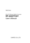
VDSL Ethernet Extender over Coax AT-MC606 Installation Guide 613-001383 Rev. A Copyright © 2010 Allied Telesis, Inc. All rights reserved. No part of this publication may be reproduced without prior written permission from Allied Telesis, Inc. Allied Telesis and the Allied Telesis logo are trademarks of Allied Telesis, Incorporated. All other product names, company names, logos or other designations mentioned herein are trademarks or registered trademarks of their respective owners Electrical Safety and Emissions Standards This product meets the following standards. U.S. Federal Communications Commission Declaration of Conformity Manufacturer Name: Allied Telesis, Inc. Declares that the product: VDSL Ethernet Extender Model Number: AT-MC606 This product complies with FCC Part 15B, Class B Limits: This device complies with part 15 of the FCC Rules. Operation is subject to the following two conditions: (1) This device must not cause harmful interference, and (2) this device must accept any interference received, including interference that may cause undesired operation. Radiated Energy Note: This equipment has been tested and found to comply with the limits for a Class B digital device pursuant to Part 15 of FCC Rules. These limits are designed to provide reasonable protection against harmful interference in a residential installation. This equipment generates, uses and can radiate radio frequency energy and, if not installed and used in accordance with instructions, may cause harmful interference to radio or television reception, which can be determined by turning the equipment off and on. The user is encouraged to try to correct the interference by one or more of the following measures: - Reorient or relocate the receiving antenna. - Increase the separation between the equipment and the receiver. - Connect the equipment into an outlet on a circuit different from that to which the receiver is connected. - Consult the dealer or an experienced radio/TV technician for help. Changes and modifications not expressly approved by the manufacturer or registrant of this equipment can void your authority to operate this equipment under Federal Communications Commission rules. Industry Canada This Class B digital apparatus complies with Canadian ICES-003. Cet appareil numérique de la classe B est conforme à la norme NMB-003 du Canada. European Union Restriction of the Use of Certain Hazardous Substances (RoHS) in Electrical and Electronic Equipment This Allied Telesis RoHS-compliant product conforms to the European Union Restriction of the Use of Certain Hazardous Substances (RoHS) in Electrical and Electronic Equipment. Allied Telesis ensures RoHS conformance by requiring supplier Declarations of Conformity, monitoring incoming materials, and maintaining manufacturing process controls. RFI Emissions FCC Class B, EN55022 Class B, EN61000-3-2, EN61000-3-3, VCCI Class B, C-TICK, CE Immunity EN55024 Electrical Safety EN60950-1 (TUV), UL 60950-1 (CULUS) 3 Translated Safety Statements Important: The symbol indicates that a translation of the safety statement is available in a PDF document titled “Translated Safety Statements”. This is posted on the Allied Telesis website at http://www.alliedtelesis.com/support/software/. Refer to “Where to Find Web-based Guides” on page 13 to navigate to this document. 4 Contents Preface ................................................................................................................................................................................11 Safety Symbols Used in this Document................................................................................................................................12 Where to Find Web-based Guides .......................................................................................................................................13 Contacting Allied Telesis ......................................................................................................................................................14 Online Support ..............................................................................................................................................................14 Email and Telephone Support .......................................................................................................................................14 Returning Products........................................................................................................................................................14 Sales or Corporate Information .....................................................................................................................................14 Warranty ........................................................................................................................................................................14 Management Software Updates ....................................................................................................................................14 Chapter 1: Summary of Features ...........................................................................................................................................................16 AT-MC606 Port Descriptions ................................................................................................................................................18 VDSL Line Port..............................................................................................................................................................18 10Base-T/100Base-Tx Ethernet Port ............................................................................................................................18 Status LEDs..........................................................................................................................................................................21 VDSL Configuration DIP Switches........................................................................................................................................22 VDSL Switch Definitions................................................................................................................................................22 VDSL Configuration DIP Switch Descriptions ...............................................................................................................23 External AC/DC Power Adapter............................................................................................................................................25 Applications for the AT-MC606 VDSL Network Extender.....................................................................................................26 Multiple Dwelling Unit (MDU) Topology.........................................................................................................................26 IP Surveillance Topology...............................................................................................................................................27 Chapter 2: Reviewing Safety Precautions ..............................................................................................................................................30 Selecting a Site for the AT-MC606 VDSL Network Extender ...............................................................................................31 Required Cabling ..................................................................................................................................................................32 Unpacking the AT-MC606 VDSL Network Extender ............................................................................................................33 Installing the AT-MC606 VDSL Network Extender Subscriber Unit......................................................................................34 Using the Subscriber Unit on a Desktop........................................................................................................................34 Wall-Mounting the Subscriber Unit ................................................................................................................................35 Cabling the Subscriber Unit...........................................................................................................................................35 Powering On the Subscriber Unit ..................................................................................................................................37 Installing the AT-MC606 VDSL Network Extender Provider Unit .........................................................................................38 Using the Provider Unit on a Desktop ...........................................................................................................................38 Wall-Mounting the Provider Unit....................................................................................................................................39 Rack-Mounting the Provider Unit...................................................................................................................................40 Cabling the Provider Unit ..............................................................................................................................................41 Powering On the Provider Unit ......................................................................................................................................41 Chapter 3: LEDs..............................................................................................................................................................................42 Appendix A: Physical Specifications .........................................................................................................................................................44 Environmental Specifications................................................................................................................................................44 Power Specifications ............................................................................................................................................................44 Safety and Electromagnetic Compatibility Certifications ......................................................................................................45 5 Contents 6 List of Figures Figure 1. AT-MC606 Front Panel.........................................................................................................................................16 Figure 2. AT-MC606 Rear Panel .........................................................................................................................................17 Figure 3. RJ-45 10Base-T/100Base-TX Connector Pin Assignments .................................................................................20 Figure 4. VDSL Configuration DIP Switches .......................................................................................................................23 Figure 5. Multiple Dwelling (MDU) Point-to-Point Topology ................................................................................................26 Figure 6. IP Surveillance Point-to-Point Topology ...............................................................................................................27 Figure 7. Attaching Protective Feet .....................................................................................................................................34 Figure 8. Configuring AT-MC606 Ethernet Extender for Subscriber Mode .........................................................................34 Figure 9. Connecting AT-MC606 Ethernet Port to Computer ..............................................................................................35 Figure 10. VDSL Line to Wall/Interior Coaxial Cable...........................................................................................................36 Figure 11. Power On the AT-MC606 Unit............................................................................................................................37 Figure 12. Attaching Protective Feet ...................................................................................................................................38 Figure 13. Configuring AT-MC606 Ethernet Extender for Provider Mode ...........................................................................39 Figure 14. Rack Mount - Set on Slider.................................................................................................................................40 Figure 15. Rack Mount - Set in Rack...................................................................................................................................40 Figure 16. Connecting AT-MC606 Ethernet Port to an Internet Service Provider ...............................................................41 7 Figures 8 List of Tables Table 1. Table 2. Table 3. Table 4. Table 5. Safety Symbols .....................................................................................................................................................12 RJ-45 Port Pinouts ...............................................................................................................................................20 Front Panel Status LEDs ......................................................................................................................................21 VDSL Configuration DIP Switches ........................................................................................................................22 AT-MC606 Cables ................................................................................................................................................32 9 Tables 10 Preface This guide contains instructions on how to install the AT-MC606 VDSL Network Extender and contains the following sections: “Safety Symbols Used in this Document” on page 12 “Where to Find Web-based Guides” on page 13 “Contacting Allied Telesis” on page 14 11 Preface Safety Symbols Used in this Document This document uses the safety symbols defined in Table 1. Table 1. Safety Symbols Symbol 12 Meaning Description Caution Performing or omitting a specific action may result in equipment damage or loss of data. Warning Performing or omitting a specific action may result in electrical shock. AT-MC606 VDSL Network Extender Installation Guide Where to Find Web-based Guides The product documentation for all Allied Telesis products are available in portable document format (PDF) on our web site. Go to http://www.alliedtelesis.com/support/software/. Enter your hardware product model in the Search by Product Name field; for example, enter AT-MC606. You can view the documents online or download them onto your local workstation or server. 13 Preface Contacting Allied Telesis This section provides Allied Telesis contact information for technical support as well as sales and corporate information. Online Support You can request technical support online by accessing the Allied Telesis Knowledge Base: www.alliedtelesis.com/support/kb.aspx. You can use the Knowledge Base to submit questions to our technical support staff and review answers to previously asked questions. Email and Telephone Support For Technical Support via email or telephone, refer to the Support & Services section of the Allied Telesis web site: www.alliedtelesis.com. Select your country from the list displayed on the website. then select the appropriate menu tab. Returning Products Products for return or repair must first be assigned a return materials authorization (RMA) number. A product sent to Allied Telesis without an RMA number will be returned to the sender at the sender’s expense. To obtain an RMA number, contact the Allied Telesis Technical Support group at our web site: www.alliedtelesis.com/support/rma. Select your country from the list displayed on the website. Then select the appropriate menu tab. Sales or Corporate Information Warranty Management Software Updates You can contact Allied Telesis for sales or corporate information through our web site: www.alliedtelesis.com. To find the contact information for your country, select Contact Us -> Worldwide Contacts. Go to www.alliedtelesis.com/support/warranty for specific terms and conditions of the warranty and for warranty registration for the AT-MC606 VDSL Network Extender. New releases of management software for our managed products are available on our Allied Telesis web site at www.alliedtelesis.com/support/software. Go to “Where to Find Web-based Guides” on page 13 for instructions on navigating to this information. 14 Chapter 1 Overview The AT-MC606 VDSL Network Extender product is designed to extend Ethernet traffic using VDSL technology over coaxial cable. This chapter contains the following sections: “Summary of Features” on page 16 “AT-MC606 Port Descriptions” on page 18 “Status LEDs” on page 21 “VDSL Configuration DIP Switches” on page 22 “External AC/DC Power Adapter” on page 25 “Applications for the AT-MC606 VDSL Network Extender” on page 26 15 Overview Summary of Features The AT-MC606 VDSL Network Extender using coaxial cable provides the following features: Extend Ethernet over shielded coaxial cable using VDSL (Very highbit-rate Digital Subscriber) protocol 10Base-T/100Base-TX Ethernet port with an RJ-45 connector – – Auto MDI/MDI-X on Ethernet port Auto-Negotiation for speed and duplex mode (IEEE 803.3u-compliant) VDSL BNC coaxial connector – – – Fast and Interleaved mode latency configurations Symmetrical and asymmetrical transmit/receive configurations Signal-to-Noise settings for different coaxial line lengths Status LEDs for both 10Base-T/100Base-TX and VDSL Line ports 12V DC external power supply input port Installation on desktop, wall, DINRAIL, or rack mounting in an AT-MCR12 Media Conversion Rack-Mount Chassis Fully EU RoHS and China RoHS compliant Figure 1. illustrates the front panel of the AT-MC606 VDSL Network Extender. Ethernet Status LEDs 10Base-T/ 100Base-TX LNK/ACT Subscriber/ Provider LED VDSL Configuration Switches VDSL CONFIG SCBR FAST ASYM 6dB LINK PWR RATE PROV INTL SYM AT-MC606 SCBR PROV VDSL LINE 100M 9dB VDSL EXTENDED ETHERNET 1931 Power LED Ethernet Port Coaxial VDSL Line Port Figure 1. AT-MC606 Front Panel 16 VDSL Line LEDs AT-MC606 VDSL Network Extender Installation Guide Figure 2. illustrates the rear panels of the AT-MC606 VDSL Network Extender. 12VDC 1563A 12 VDC Power Supply Port Figure 2. AT-MC606 Rear Panel 17 Overview AT-MC606 Port Descriptions VDSL Line Port 10Base-T/ 100Base-Tx Ethernet Port The VDSL Line port features a BNC coaxial connector. It allows you to connect two AT-MC606 VDSL Network Extender units together using an existing internal building coaxial cable. One AT-MC606 VDSL Network Extender is configured as a Provider unit and the other as a Subscriber unit. The AT-MC606 VDSL Network Extender has one 10Base-T/100Base-Tx Ethernet port which allows you to connect one AT-MC606 configured as a Subscriber unit to an Ethernet device and a second AT-MC606 configured as a Provider unit to an Ethernet Local Area Network (LAN) in the building equipment room. This twisted pair port features an RJ-45 connector with a maximum operating distance of 100 meters (328 feet). For the port pinout details, refer to “RJ-45 Port Pinouts” on page 20. Type of Cabling The 10Base-T/100Base-TX Ethernet port is designed to operate with unshielded twisted pair cables. For 10 Mbps operation, Category 3 or better 100 ohm unshielded twisted pair cabling is required. For 100 Mbps operation, Category 5 and Enhanced Category 5 (5E) 100 ohm unshielded twisted pair cabling is recommended. Auto MDI/MDI-X A 10Base-T/100Base-TX Ethernet port on a network device can have one of two possible wiring configurations: MDI or MDI-X. The Ethernet port on a PC, router, or bridge is typically wired as MDI, while the twisted pair port on a switch or hub is usually MDI-X. The AT-MC606 Ethernet port features automatic MDI/MDI-X. The port automatically determines the configuration of its end-node and then configures itself appropriately. For example, if the AT-MC606 Ethernet port is connected to a port on a bridge, which is typically wired as MDI, the AT-MC606 VDSL Network Extender automatically configures the Ethernet port to MDI-X. This feature allows you to use either straight-through or crossover cables when connecting the AT-MC606 to other Ethernet devices. Auto-Negotiation The AT-MC606 VDSL Network Extender auto-negotiates the speed and duplex mode of the Ethernet link, so that the link comes up in the highest performance configuration supported by both ends. For example, if an end node is capable of only 10 Mbps, the AT-MC606 VDSL Network Extender sets its Ethernet port to 10 Mbps or if an end node is capable of 100 Mbps, 18 AT-MC606 VDSL Network Extender Installation Guide the Ethernet port is set to 100 Mbps. Half- and Full-duplex Mode Duplex mode refers to the way an end-node sends and receives data on the network. An end-node can operate in either half- or full-duplex mode, depending on its capabilities. In half-duplex mode, data can be either sent or received, but not at the same time. In full-duplex mode, data can be sent and received simultaneously. The best network performance is achieved when an end-node can operate at full-duplex, since the end-node is able to send and receive data simultaneously. The AT-MC606 VDSL Network Extender can Auto-Negotiate to either halfor full-duplex mode, but cannot be manually configured to either mode. As a consequence, the end node must also be operating in the AutoNegotiation mode for proper operation. Note For Auto-Negotiation to operate properly, the end-nodes connected to the AT-MC606 should also use auto-negotiation. If an end-node does not have this feature and has a fixed duplex mode of fullduplex, the result will be a duplex mode mismatch with the endnode. The AT-MC606 Ethernet port ends up in the half-duplex mode if it is connected to an end-node with a fixed full-duplex mode. This configuration can produce network performance problems. Should you encounter this situation, you must configure the port on the endnode to use Auto-Negotiation or, if it lacks that feature, to halfduplex. 19 Overview RJ-45 Port Pinouts The pin assignments of an RJ-45 10Base-T/100Base-TX connector and port are illustrated in Figure 3. 1 8 8 1 Figure 3. RJ-45 10Base-T/100Base-TX Connector Pin Assignments Table 2 lists the RJ-45 10Base-T/100Base-TX connector pins and their signals when the port is operating in either MDI or MDI-X configuration. Table 2. RJ-45 Port Pinouts Pin 20 MDI Signal MDI-X Signal 1 TX+ RX+ 2 TX- RX- 3 RX+ TX+ 6 RX- TX- AT-MC606 VDSL Network Extender Installation Guide Status LEDs The AT-MC606 VDSL Network Extender features the status LEDs and are defined in Table 3. Table 3. Front Panel Status LEDs LED PWR Color Description GREEN Power is applied to the unit. OFF Power is not applied to the unit. 10Base-T/100Base-TX Ethernet Port LINK/ ACT 100M Solid GREEN A link has been established on the port. Blinking GREEN Network traffic is being transmitted and/or received. OFF A link has not been established. Solid GREEN Port is linked at 100 Mbps. OFF Port is linked at 10 Mbps when LINK/ACT LED is solid or blinking GREEN. Coaxial VDSL LINE Port SCBR/ PROV LINK RATE Solid GREEN Unit is configured as a Subscriber Unit (SCBR). OFF Unit is configured as a Provider Unit (PROV). Slow Blinking GREEN VDSL is idle when blinking occurs approximately 1 time/second. Fast Blinking GREEN VDSL is in the training or handshake mode when the blinking occurs approximately 3 times/second. Solid GREEN VDSL has established a connection with its link partner. Rapid Blinking GREEN VDSL activity is occurring when the blinking occurs approximately 6 times/second. OFF VDSL link is not established. Blinking GREEN After a VDSL link is established, the Rate LED indicates the data rate being received on the BNC port. It will continuously blink a set number of times in a set time interval. Each “blink” represents approximately 10 Mbps of VDSL line rate (e.g., six “blinks” represents a VDSL line rate of 60 Mbps). The data rates on both the Provider unit and Subscriber unit are approximately the same when configured for the SYM (symmetrical) mode and differ significantly when both are configured for the ASYM (asymmetrical) mode. See“VDSL Configuration DIP Switches” on page 22 for more information. 21 Overview VDSL Configuration DIP Switches VDSL Switch Definitions The AT-MC606 VDSL Network Extender features the four VDSL Configuration DIP switches on the front panel. The UP/DOWN positions of each switch are shown in “VDSL Configuration DIP Switches” on page 23 and defined in Table 4 below. Table 4. VDSL Configuration DIP Switches Switch Location Left Left Center Right Center Right 22 Position Switch Function UP SCBR Unit is configured for the Subscriber Mode. DOWN PROV Unit is configured for the Provider Mode. UP FAST FAST mode guarantees a minimum end to end latency less than 1 ms. DOWN INTL UP ASYM DOWN SYM UP 6 dB The unit provides optimum Signal to Noise Ratio (SNR) for VDSL line length of less than 305 meters (1000 feet). DOWN 9 dB The unit provides optimum Signal to Noise Ratio (SNR) for VDSL line length between 305 meters (1000 feet) and 3000 meters (9842 feet). Description INTL (Interleaved) mode protects from impulse noises with a duration less than 250 ms. This results in a maximum end to end latency of less than 6 ms. Asymmetrical mode adjusts the Subscriber unit line rates to be up to 100 Mbps for receive data and up to 60 Mbps for the transmit data. Symmetrical mode adjusts the receive and transmit data rates to be approximately the same in both directions for both the Subscriber and Provider units. AT-MC606 VDSL Network Extender Installation Guide The front panel VDSL Configuration DIP switches are shown in Figure 4 VDSL CONFIG SCBR FAST ASYM 6dB PROV INTL 9dB SYM 1590A Figure 4. VDSL Configuration DIP Switches VDSL Configuration DIP Switch Descriptions SCBR/PROV VDSL Configuration Switch The SCBR/PROV (Left) switch defines the function of the AT-MC606 as either a Subscriber or a Provider unit. The Subscriber (SCBR) position is selected when the AT-MC606 is used at the end point of the coaxial VDSL line where the Ethernet lines are distributed to the end-user. The Provider (PROV) position is selected when the AT-MC606 is used as the source for the coaxial VDSL line. Normally, two AT-MC606’s work together in tandem - one as a Subscriber unit and the other as a Provider unit. FAST/INTL VDSL Configuration Switch The FAST/INTL (Left Center) switch is used when noise compensation is required. If the coaxial VDSL line is operating in a relatively low noise environment, the data link and data transmission are usually reliable. The FAST position is recommended in this case. This operating mode has the advantage of short latency times - usually less than 1 ms. You will want to select the INTL (Interleaved) position if you notice that the VDSL link is being repeatedly dropped or data is being lost, excessive noise bursts on the line may be the cause. With the Interleaved selection, the transmitted data is combined or interleaved with data correction code. This combination reduces the data errors, packet losses and loss of sync caused by a noisy environment. However, because the additional data correction code is added to the data stream, the overall transmission latency will increase and is usually less than 6 ms. The overall effect of this setting is more reliable data transmissions in a noisy environment. 23 Overview ASYM/SYM VDSL Configuration Switch The ASYM/SYM (Right Center) switch selects the maximum data rate for the VDSL line. The ASYM (asymmetrical) position is the factory default position, which allows the Subscriber a maximum receive data rate of 100 Mbps and a maximum transmit data rate of 60 Mbps. The SYM (symmetrical) position limits the receive and transmit line rates in a symmetrical manner so the line rates in both directions are approximately the same. 6 dB/9 dB VDSL Configuration Switch The 6 dB/9 dB (Right) switch selects the optimum signal to noise ratio (SNR) for your VDSL line which is dependent on the line length of the coaxial cable. The factory default setting for this switch is 6 dB SNR and assumes that your VDSL line is less than 305 meters (1000 feet) in length. Select the 9 dB SNR setting if your VDSL line is between 305 meters and 3000 meters (9842 feet) or if a more stable link and more noise protection is needed. 24 AT-MC606 VDSL Network Extender Installation Guide External AC/DC Power Adapter An external, energy efficient, AC/DC power adapter is included with the AT-MC606 VDSL Network Extender for desktop or wall-mount operation. The power adapter supplies 12V DC to the AT-MC606. Allied Telesis supplies an approved safety compliant AC power adapter specifically designed for each region where the AT-MC606 VDSL Network Extender is sold. Each type of power adapter has an unregulated output of 12V DC at 1A. The AT-MC606 VDSL Network Extender has a single DC power supply socket on the back panel. The unit does not have a power switch. To turn the unit ON or OFF, you must connect or disconnect the DC power cord. 25 Overview Applications for the AT-MC606 VDSL Network Extender The AT-MC606 VDSL Network Extender is designed to be used in pairs to extend Ethernet traffic over existing coaxial cables in a building. One AT-MC606 is configured as the subscriber unit and the second unit is configured as the provider unit. You must manually configure these units as a subscriber or provider unit when installed. If you plan to install multiple AT-MC606s in a rack or on a desktop, the AT-MCR12 chassis can accommodate up to 12 units. The DC power for all of the AT-MC606s is provided by an internal power supply within the AT-MCR12 chassis. Multiple Dwelling Unit (MDU) Topology The AT-MC606’s can be used is in multi-dwelling units (MDU), multitenant buildings (MTU) or in the hospitality industry, such as airports, hotels, and convention centers. For example, Figure 5 illustrates a pointto-point topology for an MDU building where internet services are delivered to each room using VDSL via the building’s coaxial cable wiring. ADSL AT-AR440 Internet 1 3 5 7 9 11 13 15 17 19 21R 23R 2 4 6 8 10 12 14 16 18 20 22R 24R AT-9424T Gigabit Ethernet Switch PORT ACTIVITY CLASS 1 LASER PRODUCT L/A D/C 1000 LINK / FDX ACT 10/100 LINK / HDX / COL SFP ACT L/A 1 3 5 7 9 11 13 15 17 19 21R 23R 2 4 6 8 10 12 14 16 18 20 22R 24R L/A SFP D/C 22 23 TERMINAL PORT STATUS 21 FAULT 22 MASTER 23 L/A 24 D/C 21 POWER 24 POWER MCR12 12 AT-MC606 Provider Units mounted in an AT-MCR12 Chassis Building Equipment Room Existing Coaxial Cabling in Building Guest Room Subscriber Unit 10Base-T/ 100Base-TX LNK/ACT VDSL CONFIG SCBR FAST ASYM 6dB PROV INTL SYM 9dB SCBR PROV VDSL LINE LINK 100M PWR AT-MC606 RATE VDSL EXTENDED ETHERNET Guest Room Subscriber Unit 10Base-T/ 100Base-TX LNK/ACT . . . . . . . . . . . VDSL CONFIG SCBR FAST ASYM 6dB PROV INTL SYM 9dB SCBR PROV VDSL LINE LINK 100M RATE PWR AT-MC606 VDSL EXTENDED ETHERNET Guest Room Subscriber Unit 10Base-T/ 100Base-TX LNK/ACT VDSL CONFIG SCBR FAST ASYM 6dB PROV INTL SYM 9dB LINK RATE PWR AT-MC606 SCBR PROV VDSL LINE 100M VDSL EXTENDED ETHERNET . . . Guest Room Subscriber Unit 10Base-T/ 100Base-TX LNK/ACT VDSL CONFIG SCBR FAST ASYM 6dB PROV INTL SYM 9dB LINK PWR AT-MC606 SCBR PROV VDSL LINE 100M RATE VDSL EXTENDED ETHERNET 1933 Figure 5. Multiple Dwelling (MDU) Point-to-Point Topology An AT-MC606 Subscriber unit is installed in each guest room while the corresponding AT-MC606 Provider units are located in the building’s central equipment room and are individually assigned to each office. The Provider units are rack mounted together in AT-MCR12 chassis and their Ethernet ports are connected via an Ethernet LAN to the building’s internet service. Both Subscriber and Provider units are configured 26 AT-MC606 VDSL Network Extender Installation Guide for Asymmetrical data mode to maximize the amount of data being sent to the Subscriber and minimize the amount of data being sent to the Provider. IP Surveillance Topology Another example is using the AT-MC606 for connecting IP surveillance cameras with a Ethernet Local Area Network (LAN) using existing coaxial cables within the building. For example, Figure 5 illustrates a point-to-point topology between individual IP surveillance cameras and an Ethernet LAN and Surveillance camera server using VDSL via the building’s existing coaxial cable wiring. ADSL AT-AR440 Internet 1 3 5 7 9 11 13 15 17 19 21R 23R 2 4 6 8 10 12 14 16 18 20 22R 24R AT-9424T Gigabit Ethernet Switch PORT ACTIVITY CLASS 1 LASER PRODUCT L/A D/C 1000 LINK / FDX ACT 10/100 LINK / HDX / COL SFP ACT L/A 1 3 5 7 9 11 13 15 17 19 21R 23R 2 4 6 8 10 12 14 16 18 20 22R 24R L/A SFP D/C 22 23 TERMINAL PORT STATUS 21 FAULT 22 MASTER 23 L/A 24 D/C 21 POWER 24 POWER MCR12 12 AT-MC606 Subscriber Units mounted in an AT-MCR12 Chassis Surveillance Camera Server Building Equipment Room Existing Coaxial Cabling in Building Surveillance IP Camera Provider Unit 10Base-T/ 100Base-TX LNK/ACT VDSL CONFIG SCBR FAST ASYM 6dB PROV INTL SYM 9dB LINK RATE PWR AT-MC606 VDSL EXTENDED ETHERNET Surveillance IP Camera Provider Unit 10Base-T/ 100Base-TX LNK/ACT VDSL CONFIG SCBR FAST ASYM 6dB PROV INTL SYM 9dB LINK PWR AT-MC606 RATE VDSL EXTENDED ETHERNET Surveillance IP Camera Provider Unit 10Base-T/ 100Base-TX LNK/ACT VDSL CONFIG SCBR FAST ASYM 6dB PROV INTL SYM 9dB LINK RATE PWR AT-MC606 VDSL EXTENDED ETHERNET Surveillance IP Camera Provider Unit 10Base-T/ 100Base-TX LNK/ACT VDSL CONFIG SCBR FAST ASYM 6dB PROV INTL SYM 9dB LINK PWR AT-MC606 SCBR PROV VDSL LINE 100M 100 Meters Max SCBR PROV VDSL LINE 100M 100 Meters Max SCBR PROV VDSL LINE 100M 100 Meters Max SCBR PROV VDSL LINE 100M 100 Meters Max RATE VDSL EXTENDED ETHERNET 1942 Figure 6. IP Surveillance Point-to-Point Topology In this case, each AT-MC606 Provider unit is installed within 100 meters of its IP Surveillance camera and is connected with a standard Ethernet cable. (Since the AT-MC606 features auto MDI/MDI-X, you may use either a cross-over or straight-through cable.)The AT-MC606 Subscriber units are located in the building’s central equipment room and are connected to the Provider unit/camera combination over existing building coaxial cables. The Subscriber units are rack mounted together in AT-MCR12 chassis and their Ethernet ports are connected to an Ethernet LAN. In this example, the Surveillance camera data server is connected to the same LAN. Through this connection, the server is capable of receiving Ethernet video data from each camera, while sending Ethernet control data to the cameras. Both Subscriber and Provider units are configured for asymmetrical data mode to maximize the amount of data being sent to the Subscriber and minimize the amount of data being sent to the Provider. 27 Chapter 2 Installation This chapter contains the installation procedures for the AT-MC606 VDSL Network Extender in the following sections: “Reviewing Safety Precautions” on page 30 “Selecting a Site for the AT-MC606 VDSL Network Extender” on page 31 “Required Cabling” on page 32 “Unpacking the AT-MC606 VDSL Network Extender” on page 33 “Installing the AT-MC606 VDSL Network Extender Subscriber Unit” on page 34 “Installing the AT-MC606 VDSL Network Extender Provider Unit” on page 38 29 Overview Reviewing Safety Precautions Please review the following safety precautions before you begin to install the switch or any of its components. The indicates that a translation of the safety statements is available in a PDF document titled “Translated Safety Statements”. This other product documentation is posted on the Allied Telesis website at http://www.alliedtelesis.com/support/ software/. Enter your hardware product model in the Search by Product Name field; for example, enter AT-MC606. You can view the documents online or download them onto your local workstation or server. Warning: Do not work on equipment or cables during periods of lightning activity. E2 Warning: To prevent electric shock, do not remove the cover. No user-serviceable parts inside. This unit contains hazardous voltages and should only be opened by a trained and qualified technician. To avoid the possibility of electric shock, disconnect electric power to the product before connecting or disconnecting the LAN cables. E3 Warning: Class I Equipment. This equipment must be earthed. The power plug must be connected to a properly wired earth ground socket outlet. An improperly wired socket outlet could place hazardous voltages on accessible metal parts. E6 Pluggable Equipment. The socket outlet shall be installed near the equipment and shall be easily accessible. E7 Caution: Air vents must not be blocked and must have free access to the room ambient air for cooling. E8 30 AT-MC606 VDSL Network Extender Installation Guide Selecting a Site for the AT-MC606 VDSL Network Extender Observe the following requirements when choosing a site for your AT-MC606 VDSL Network Extender: If you plan to install a AT-MC606 VDSL Network Extender into an ATMCR12 rackmount chassis and equipment rack, check to be sure that the rack is safely secured and that it will not tip over. Devices in a rack should be installed starting at the bottom, with the heavier devices near the bottom of the rack. The AT-MC606 VDSL Network Extender may be wall mounted either on a DINRAIL using a DINRAIL bracket or using an AT-WLMT bracket. Both brackets are provide separately. Select a place on the wall that provides the best cabling and power access. Note Both the DINRAIL bracket and the AT-WLMT wall mount bracket are sold separately. Contact your Allied Telesis Sales representative to purchase these items. If you are installing the AT-MC606 VDSL Network Extender on a table, be sure that the table is level and secure. The power outlet for the AT-MC606 VDSL Network Extender should be located near the unit and should be easily accessible. The site should provide for easy access to the ports on the front of the AT-MC606 VDSL Network Extender. This makes it easy for you to connect and disconnect cables, as well as view the LEDs. To allow proper cooling of the AT-MC606 VDSL Network Extender, air flow around the unit and through its vents on the side should not be restricted. Do not place objects on top of the AT-MC606 VDSL Network Extender. Do not expose the AT-MC606 VDSL Network Extender to moisture or water. Make sure that the site is a dust-free environment. You should use dedicated power circuits or power conditioners to supply reliable electrical power to the AT-MC606 VDSL Network Extender. 31 Overview Required Cabling The AT-MC606 VDSL Network Extender requires two or more of the three cables described in Table 5 below. These cables are not shipped with the AT-MC606. Table 5. AT-MC606 Cables Port 32 Cable Connector Ethernet Category 3 or better 100-ohm unshielded straight-through or crossover twisted pair cable RJ-45 VDSL Line 50 or 75 ohm coaxial cable BNC AT-MC606 VDSL Network Extender Installation Guide Unpacking the AT-MC606 VDSL Network Extender To unpack the AT-MC606 product: 1. Remove all components from the shipping package and store the packaging material in a safe location. 2. Make sure the following hardware components are included in your AT-MC606 package. If any item is missing or damaged, contact your Allied Telesis sales representative for assistance. One AT-MC606 VDSL Network Extender Four protective feet One universal energy efficient power adapter 33 Overview Installing the AT-MC606 VDSL Network Extender Subscriber Unit The AT-MC606 Subscriber unit is normally used as a stand-alone device, or can be used as a desktop device, or mounted to a wall. Using the Subscriber Unit on a Desktop To use the Subscriber unit on a desktop, perform the following procedure: 1. Remove all equipment from the package and store the packaging material in a safe place. 2. Attach the four protective feet (provided) to each corner of the bottom of the unit, as illustrated in Figure 7. AT-MC606 VDSL EXTENDED ETHERNET PROV INTL SYM 9dB RATE PWR LINK 100M 10Base-T/ 100Base-TX LNK/ACT VDSL LINE SCBR FAST ASYM 6dB SCBR PROV VDSL CONFIG 1932 Figure 7. Attaching Protective Feet 3. Position the AT-MC606 on the desktop. 4. Configure the right VDSL CONFIG switch (SCBR/PROV) to the SCBR position as shown in Figure 8. VDSL CONFIG SCBR FAST ASYM 6dB PROV INTL SYM 9dB 1936 Figure 8. Configuring AT-MC606 Ethernet Extender for Subscriber Mode 34 AT-MC606 VDSL Network Extender Installation Guide 5. Go to “Cabling the Subscriber Unit” on page 35 to connect the cables and to “Powering On the Subscriber Unit” on page 37 for powering the unit. Wall-Mounting the Subscriber Unit The AT-MC606 VDSL Network Extender may be wall mounted directly to the wall with an AT-WLMT Wall Mount Bracket or by using an Allied Telesis DINRAIL Bracket (both supplied separately) in conjunction with a previously mounted DINRAIL. 1. Configure the right VDSL CONFIG switch (SCBR/PROV) to the SCBR position as shown in Figure 8, ”Configuring AT-MC606 Ethernet Extender for Subscriber Mode” on page 34. 2. Follow the installation instructions supplied with the wall mounting bracket. 3. Go to “Cabling the Subscriber Unit” on page 35 to connect the cables and to “Powering On the Subscriber Unit” on page 37 for powering the unit. Cabling the Subscriber Unit To cable the Subscriber unit to a computer, perform the following steps: 1. Connect the Ethernet cable from the AT-MC606 Ethernet port to the Ethernet port on your computer, as shown in Figure 9. 10 100BBase-T/ ase-T X LNK/A CT 100M VDSL SCBR PWR AT-M C6 06 FAST PROV INTL VDSL EXTE NDED CONF ASYM SYM ETH IG 6dB VDSL 9dB LINE ERN ET LINK SCBR PROV RATE 1937 Figure 9. Connecting AT-MC606 Ethernet Port to Computer 35 Overview 2. Connect a coaxial cable from the VDSL Line port to the wall/interior coaxial cable, as shown in Figure 10, so that the Subscriber unit can communicate with the Provider unit. 10Ba 100B se-T/ ase-T X LNK/A CT SCBR PROV VDSL LINE LINK RATE MCR12 100M VDSL SCBR 9dB 6dB VDSL CONFIG PROV INTL SYM SCBR FAST ASYM 06 PROV VDS L EXT END FAST INTL CON FIG ASYM SYM ED ETH 6dB VDSL LINE 9dB ERN ET LINK SCBR PROV RATE AT-MC606 PWR 100M 10Base-T/ 100Base-TX LNK/ACT VDSL EXTENDED ETHERNET PWR AT-M C6 1938 Subscriber Unit Provider Unit Wall/Interior Coax Cable Used as VDSL Line Figure 10. VDSL Line to Wall/Interior Coaxial Cable Note The AT-MC606 coax connector has a built-in termination, so an external termination is not required. 36 AT-MC606 VDSL Network Extender Installation Guide Powering On the Subscriber Unit Power on the Subscriber unit using the power adapter provided, as shown in Figure 11. 12 V D C Figure 11. Power On the AT-MC606 Unit 37 Overview Installing the AT-MC606 VDSL Network Extender Provider Unit The AT-MC606 Provider unit can either be installed in an AT-MCR12 rackmount chassis, or used as a desktop device, or mounted onto a wall. Warning To prevent exposure to electric shock, the AT-MC606 Provider Unit must be installed in a RESTRICTED ACCESS LOCATION and performed by QUALIFIED SERVICE PERSONNEL. Note For Finland, Norway, and Sweden – When the AT-MC606 Ethernet Extender and the AT-MCR12 rackmount chassis are used, a permanent ground conductor must be installed on the AT-MCR12 rackmount chassis. For installation instructions of this ground conductor, the AT-MCR12 Media Converter Rackmount Chassis Installation Manual is available in portable document format (PDF) on our web site at www.alliedtelesis.com. Go to “Where to Find Web-based Guides” on page 13 for instructions to navigate to this documentation. Using the Provider Unit on a Desktop To use the Provider unit on a desktop, perform the following procedure: 1. Remove all equipment from the package and store the packaging material in a safe place. 2. Attach the four protective feet (provided) to each corner of the bottom of the unit, as illustrated in Figure 12. . AT-MC606 VDSL EXTENDED ETHERNET PROV INTL SYM 9dB RATE PWR LINK 100M 10Base-T/ 100Base-TX LNK/ACT VDSL LINE SCBR FAST ASYM 6dB SCBR PROV VDSL CONFIG 1932 Figure 12. Attaching Protective Feet 38 AT-MC606 VDSL Network Extender Installation Guide 3. Configure the right VDSL CONFIG switch (SCBR/PROV) to the SCBR position as shown in Figure 13. VDSL CONFIG SCBR FAST ASYM 6dB PROV INTL SYM 9dB 1935 Figure 13. Configuring AT-MC606 Ethernet Extender for Provider Mode 4. Go to “Cabling the Provider Unit” on page 41 to connect the cables and to “Powering On the Provider Unit” on page 41 for powering the unit. Wall-Mounting the Provider Unit The AT-MC606 VDSL Network Extender may be wall mounted directly to the wall with an AT-WLMT Wall Mount Bracket or by using an Allied Telesis DINRAIL Bracket in conjunction with a previously mounted DINRAIL. Both of these brackets may be ordered separately from the AT-MC606. Please contact your local Allied Telesis representative. 1. Configure the right VDSL CONFIG switch (SCBR/PROV) to the SCBR position as shown in Figure 13. 2. Follow the installation instructions supplied with the wall mounting bracket or DINRAIL bracket. 3. To connect the cables, see “Cabling the Provider Unit” on page 41. 4. To apply power to the unit, see “Powering On the Provider Unit” on page 41. 39 Overview Rack-Mounting the Provider Unit To install the Provider unit in an AT-MCR12 rackmount chassis, perform the following steps: 1. Configure the right VDSL CONFIG switch (SCBR/PROV) to the SCBR position as shown in Figure 13 on page 39. VDSL CONFIG RATE PROV INTL RATE LIMIT 9dB VDSL EXTENDED ETHERNET SCBR FAST NO LIMIT 6dB PWR 100M 10Base-T/ 100Base-TX LNK/ACT AT-MC606 VDSL LINE SCBR PROV LINK 2. Attach the unit to one of the sliders that holds the unit in the chassis, as shown in Figure 14. 1636 Figure 14. Rack Mount - Set on Slider 3. Position the slider, as shown in Figure 15 and push into the chassis. R POWE LINK RATE PWR AT-MC606 9dB 6dB VDSL CONFIG PROV INTL SYM SCBR FAST ASYM 10Base-T/ 100Base-TX LNK/ACT VDSL EXTENDED ETHERNET VDSL LINE 100M SCBR PROV MCR12 1939 Figure 15. Rack Mount - Set in Rack 4. To connect the cables, see “Cabling the Provider Unit” on page 41. 40 AT-MC606 VDSL Network Extender Installation Guide Cabling the Provider Unit To cable the Provider unit, perform the following steps: 1. Connect the Ethernet cable from the Ethernet port to the Service Provider box (ISP) in your wiring closet, as shown in Figure 16. Internet AT-MC606 SCBR PROV LINK 9dB 6dB VDSL CONFIG PROV INTL SYM SCBR FAST ASYM PWR 100M 10Base-T/ 100Base-TX LNK/ACT VDSL EXTENDED ETHERNET VDSL LINE RATE MCR12 1940 Figure 16. Connecting AT-MC606 Ethernet Port to an Internet Service Provider 2. Connect a coaxial cable from the VDSL Line port to the wall/interior coaxial cable, as shown in Figure 10 on page 36, so that the Provider unit can communicate with the Subscriber unit. Powering On the Provider Unit If you have rack mounted the AT-MC606 Provider unit in an AT-MCR12 rackmount chassis, the chassis must be powered on which provides power to the AT-MC606. Warning The QUALIFIED SERVICE PERSONNEL must verify that the AT-MCR12 rackmount chassis power cord is connected to the socket provided with the ground conductor. If the power cord is not connected, the QUALIFIED SERVICE PERSONNEL must install a permanent ground connection using the bond stud on the rear panel of the AT-MCR12 rackmount chassis. For detailed information on how to power on the AT-MCR12 rackmount chassis, refer to the AT-MCR12 Media Converter Rackmount Chassis Installation Manual. If you have installed a stand alone AT-MC606 Provider unit, power on the unit using the power adapter provided, as shown in Figure 11 on page 37. 41 Chapter 3 Troubleshooting This chapter contains information on how to troubleshoot the AT-MC606 VDSL Network Extender in the event a problem occurs. Note If after following the instructions in this chapter you are unable to resolve the problem, contact Allied Telesis Technical Support for assistance. Refer to “Contacting Allied Telesis” on page 14 for information on how to contact our Technical Support Department. LEDs Check the LEDs on the AT-MC606 front panel for proper operation. Refer to “AT-MC606 Front Panel” on page 16 for the LED locations and Table 3 on page 21 for the LED functional descriptions. Power LED Check the PWR LED on the front of the AT-MC606 VDSL Network Extender. If the LED is OFF, indicating that the AT-MC606 is not receiving power, do the following: If the AT-MC606 is inserted in the AT-MCR12 rackmount chassis, make sure that the power cord is securely connected to the power source and to the power connector on the back panel of the AT-MCR12 rackmount chassis. If the AT-MC606 is in a stand-alone configuration, make sure that the AC/DC power adapter is securely connected to both the power source and the DC power connector on the back panel of the AT-MC606. Verify that the AC power outlet has power by connecting another device to it. Try connecting the AT-MC606 to another AC power source. Try using a different power cord or a different AC/DC power adapter. Check that the voltage from the power source is within the required levels for your region. 42 AT-MC606 VDSL Network Extender Installation Guide LINK/ACT LED - 10Base-T/100BaseTX Ethernet Port Verify that the LINK/ACT LED for the 10Base-T/100BaseTX Ethernet port is ON. If a LINK/ACT LED is OFF, do the following: Verify that the end node connected to the port is powered ON and is operating properly. Check that the twisted pair cable is securely connected to the port on the AT-MC606 and to the port on the end node. Make sure that the twisted pair cable does not exceed 100 meters (328 feet). Verify that you are using the appropriate category of twisted pair cable: Category 3 or better for 10 Mbps operation, Category 5 and Category 5E for 100 Mbps operation. Make sure that the operating parameters of the port on the AT-MC606 are compatible with the end node to which the port is connected. LINK LED - Coaxial VDSL LINE Port Verify that the LINK LED for the coaxial VDSL LINE port is either solid green, slow blinking green (approximately 1 time/second), or rapidly blinking green (approximately 6 times/second. If a LINK LED is OFF, do the following: Check that the coaxial cable is securely connected to the port on the AT-MC606 and to the port on the end node. Verify that the end node connected to the port is powered ON and is operating properly. Verify that one of the AT-MC606 modules is configured as the Subscriber unit and the second AT-MC606 module is configured as the Provider unit. It is normal for the coaxial VDSL LINE port LINK LED to blink approximately 3 times/second when the training or handshake mode occurs. It is not normal for the training or handshake mode to continue for more than 1 minute before indicating an idle or link condition. If this abnormal condition occurs, do the following: Check that the coaxial cable is securely connected to the port on the AT-MC606 and to the port on the end node. Verify that the end node connected to the port is powered ON and is operating properly. Verify that one of the AT-MC606 modules is configured as the Subscriber unit and the second AT-MC606 module is configured as the Provider unit. 43 Appendix A Technical Specifications Physical Specifications Dimensions: (W x D x H) 109 mm x 95 mm x 25 mm (4.29 in. x 3.74 in. x 0.98 in.) Weight: .3 kg (0.66 lbs) Recommended Minimum Clearance on All Sides: 5.08 cm (2.0 in.) Environmental Specifications Operating Temperature: 0° C to 40° C Storage Temperature: -25° C to 70° C Operating Humidity: 5% to 90% (noncondensing) Storage Humidity: 5% to 95% (noncondensing) Operating Altitude: 3,000 m Non-operating Altitude: 4,000 m Power Specifications Power Consumption: 4 Watts Input Supply Current: 350 mA Input Supply Voltage: 12V DC 44 AT-MC606 VDSL Network Extender Installation Guide Safety and Electromagnetic Compatibility Certifications Emission: EN55022 Class B, FCC Part 15 Class B Immunity: EN55024 Safety: EN60950-1, UL60950-1 45