1
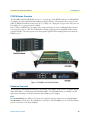
ForeFront Model FF3310 Series G.SHDSL.bis DSLAM User Manual FF3310P only. This is a Class A device and is not intended for use in a residential environment. Sales Office: +1 (301) 975-1000 Technical Support: +1 (301) 975-1007 E-mail: [email protected] WWW: www.patton.com Part Number: 07MFF3310-UM, Rev. B Revised: October 21, 2014 Patton Electronics Company, Inc. 7622 Rickenbacker Drive Gaithersburg, MD 20879 USA tel: +1 (301) 975-1000 fax: +1 (301) 869-9293 support: +1 (301) 975-1007 web: www.patton.com e-mail: [email protected] Copyright © 2013–2014, Patton Electronics Company. All rights reserved. The information in this document is subject to change without notice. Patton Electronics assumes no liability for errors that may appear in this document. Important Information To use virtual private network (VPN) and/or AES/DES/3DES encryption capabilities with the ForeFront, you may need to purchase additional licenses, hardware, software, network connection, and/or service. Contact [email protected] or +1 (301) 975-1000 for assistance. Warranty Information Patton Electronics warrants all ForeFront components to be free from defects, and will—at our option—repair or replace the product should it fail within one year from the first date of the shipment. This warranty is limited to defects in workmanship or materials, and does not cover customer damage, abuse or unauthorized modification. If the product fails to perform as warranted, your sole recourse shall be repair or replacement as described above. Under no condition shall Patton Electronics be liable for any damages incurred by the use of this product. These damages include, but are not limited to, the following: lost profits, lost savings and incidental or consequential damages arising from the use of or inability to use this product. Patton Electronics specifically disclaims all other warranties, expressed or implied, and the installation or use of this product shall be deemed an acceptance of these terms by the user. Summary Table of Contents 1 Introduction...................................................................................................................................................... 13 2 Hardware Installation ....................................................................................................................................... 18 3 Initial Configuration ......................................................................................................................................... 24 4 Operation and Shutdown.................................................................................................................................. 29 5 Contacting Patton for Assistance....................................................................................................................... 31 A Compliance Information .................................................................................................................................. 34 B Specifications ................................................................................................................................................... 37 C Network Ports (RJ-21X) Connector Pin-out .................................................................................................... 39 3 Table of Contents About This Guide ............................................................................................................................... 9 Audience................................................................................................................................................................. 9 Structure................................................................................................................................................................. 9 Precautions ............................................................................................................................................................. 9 Safety When Working with Electricity ............................................................................................................10 WEEE Notice .................................................................................................................................................11 ESD Warning .................................................................................................................................................11 General Observations ......................................................................................................................................11 Typographical Conventions Used in this Document ............................................................................................ 11 General Conventions ......................................................................................................................................12 Mouse Conventions ........................................................................................................................................12 1 Introduction...................................................................................................................................................... 13 FF3310 Series Overview ........................................................................................................................................14 Hardware Overview...............................................................................................................................................14 LAN ...............................................................................................................................................................14 RS-232 Control Port ......................................................................................................................................15 FF3310P and FF3310RC Power Systems .......................................................................................................15 G.SHDSL.bis Ports .........................................................................................................................................15 Temperature ...................................................................................................................................................15 Humidity ........................................................................................................................................................15 Physical Dimensions .......................................................................................................................................15 FF3310RC ................................................................................................................................................15 FF3310P ...................................................................................................................................................15 Management Services ......................................................................................................................................15 LED Display .........................................................................................................................................................16 AC Power Considerations......................................................................................................................................17 2 Hardware Installation ....................................................................................................................................... 18 Introduction ..........................................................................................................................................................19 Unpacking the FF3310P .......................................................................................................................................19 FF3310P Installation.............................................................................................................................................19 FF3310P Cable Installation ...................................................................................................................................20 Grounding the FF3310P—AC Power Supplies ...............................................................................................20 Installing the AC Power Cables .......................................................................................................................21 Connecting the Ethernet Ports ........................................................................................................................21 Connecting the 10/100/1000Base-TX Ethernet ports to an Ethernet switch, hub or workstation .............22 Connecting the EIA-561 RS-232 Configuration Port (DCE configured) ........................................................22 Connecting the DSL Ports ..............................................................................................................................23 Completing the Hardware Installation...................................................................................................................23 AC Units ........................................................................................................................................................23 4 3 Initial Configuration ......................................................................................................................................... 24 Introduction ..........................................................................................................................................................25 1. Connecting the FF3310 to Your PC..................................................................................................................25 Connecting and Logging in via the Ethernet Port ...........................................................................................25 Connecting and Logging in via the Console Port ............................................................................................26 2. Configuring the Desired IP Address ..................................................................................................................27 Factory-default IP Settings ..............................................................................................................................27 Login ..............................................................................................................................................................27 Changing the IP Address .................................................................................................................................27 Saving the IP Address ......................................................................................................................................27 3. Connecting the FF3310 to the Network............................................................................................................28 4 Operation and Shutdown.................................................................................................................................. 29 Introduction ..........................................................................................................................................................30 Activating the FF3310...........................................................................................................................................30 De-activating the FF3310......................................................................................................................................30 5 Contacting Patton for Assistance....................................................................................................................... 31 Introduction ..........................................................................................................................................................32 Contact Information .............................................................................................................................................32 Warranty Service and Returned Merchandise Authorizations (RMAs)...................................................................32 Warranty Coverage .........................................................................................................................................32 Out-of-warranty service .............................................................................................................................32 Returns for credit ......................................................................................................................................32 Return for credit policy .............................................................................................................................33 RMA Numbers ...............................................................................................................................................33 Shipping instructions ................................................................................................................................33 A Compliance Information .................................................................................................................................. 34 FF3310P Only: EMC Directive ............................................................................................................................35 FF3310P Only: Low-Voltage Directive (Safety) ....................................................................................................35 FF3310P Only: PSTN ..........................................................................................................................................35 FF3310P Only: Radio and TV Interference Statement (FCC Part 15) ..................................................................35 FF3310P Only: CE Declaration of Conformity.....................................................................................................35 FF3310P Only: Authorized European Representative............................................................................................35 FF3310P Only: FCC Part 68 (ACTA) Statement..................................................................................................35 ESD Warning........................................................................................................................................................36 B Specifications ................................................................................................................................................... 37 DSL Ports..............................................................................................................................................................38 Ethernet Ports .......................................................................................................................................................38 Power Supplies ......................................................................................................................................................38 Management Service..............................................................................................................................................38 Alarm Reporting....................................................................................................................................................38 Environment .........................................................................................................................................................38 Dimensions ...........................................................................................................................................................38 5 Model 2960 RAS Getting Started Guide FF3310RC ......................................................................................................................................................38 FF3310P .........................................................................................................................................................38 C Network Ports (RJ-21X) Connector Pin-out .................................................................................................... 39 Introduction ..........................................................................................................................................................40 6 List of Figures 1 2 3 4 5 6 7 8 9 10 FF3310RC and FF3310P Models . . . . . . . . . . . . . . . . . . . . . . . . . . . . . . . . . . . . . . . . . . . . . . . . . . . . . . . . . . . 14 Model FF3310P front and rear panel LEDs . . . . . . . . . . . . . . . . . . . . . . . . . . . . . . . . . . . . . . . . . . . . . . . . . . . 16 Model FF3310RC front and rear panel LEDs . . . . . . . . . . . . . . . . . . . . . . . . . . . . . . . . . . . . . . . . . . . . . . . . . . 16 IEC-320 connector and grounding stud locations . . . . . . . . . . . . . . . . . . . . . . . . . . . . . . . . . . . . . . . . . . . . . . . 20 FF3310RC and FF3310P network and configuration ports . . . . . . . . . . . . . . . . . . . . . . . . . . . . . . . . . . . . . . . 22 DB-9-to-RJ-45 cable diagram . . . . . . . . . . . . . . . . . . . . . . . . . . . . . . . . . . . . . . . . . . . . . . . . . . . . . . . . . . . . . . 23 Connecting the FF3310 to your laptop PC via the Ethernet port . . . . . . . . . . . . . . . . . . . . . . . . . . . . . . . . . . . 25 Connecting the FF3310RC or FF3310P to your laptop PC via the console port . . . . . . . . . . . . . . . . . . . . . . . 26 50-pin Teleco connector . . . . . . . . . . . . . . . . . . . . . . . . . . . . . . . . . . . . . . . . . . . . . . . . . . . . . . . . . . . . . . . . . . 40 Patch Panel cable connections . . . . . . . . . . . . . . . . . . . . . . . . . . . . . . . . . . . . . . . . . . . . . . . . . . . . . . . . . . . . . 40 7 List of Tables 1 2 3 4 FF3310RC and FF3310P LED descriptions . . . . . . . . . . . . . . . . . . . . . . . . . . . . . . . . . . . . . . . . . . . . . . . . . . . 17 RJ-45 Ethernet cable diagram . . . . . . . . . . . . . . . . . . . . . . . . . . . . . . . . . . . . . . . . . . . . . . . . . . . . . . . . . . . . . . 22 Factory default IP address and network mask configuration . . . . . . . . . . . . . . . . . . . . . . . . . . . . . . . . . . . . . . . 27 Band Marked Color Code . . . . . . . . . . . . . . . . . . . . . . . . . . . . . . . . . . . . . . . . . . . . . . . . . . . . . . . . . . . . . . . . 40 8 About This Guide This guide describes installing and operating the Patton Electronics ForeFront Model FF3310 Series. Audience This guide is intended for the following users: • Operators • Installers • Maintenance technicians Structure This guide contains the following chapters and appendices: • Chapter 1 on page 13 describes the ForeFront Model FF3310 Series • Chapter 2 on page 18 describes installing the FF3310 hardware • Chapter 3 on page 24 configuring the FF3310 for use • Chapter 4 on page 29 details how to power up and deactivate the FF3310 • Chapter 5 on page 31 contains information on contacting Patton technical support for assistance • Appendix A on page 34 contains compliance information for the FF3310 • Appendix B on page 37 contains specifications for the FF3310 • Appendix C on page 39 contains the pinout for the network ports connector For best results, read the contents of this guide before you install the DSLAM. Precautions Notes, cautions, and warnings, which have the following meanings, are used throughout this guide to help you become aware of potential problems. Warnings relate to personal injury issues, and Cautions refer to potential property damage. . The shock hazard symbol and WARNING heading indicate a potential electric shock hazard. Strictly follow the warning instructions to avoid injury caused by electric shock. The alert symbol and WARNING heading indicate a potential safety hazard. Strictly follow the warning instructions to avoid personal injury. The shock hazard symbol and CAUTION heading indicate a potential electric shock hazard. Strictly follow the instructions to avoid property damage caused by electric shock. 9 ForeFront 3310 Series User Manual The alert symbol and CAUTION heading indicate a potential hazard. Strictly follow the instructions to avoid property damage. The alert symbol and IMPORTANT heading calls attention to important information. Note A note presents additional information or interesting sidelights. Safety When Working with Electricity This section includes safety and electrical warnings for installing the device.. • Do not open the device when the power cord is connected. For systems without a power switch and without an external power adapter, line voltages are present within the device when the power cord is connected. • For devices with an external power adapter, the power adapter shall be a listed Limited Power Source. The mains outlet that is utilized to power the device shall be within 10 feet (3 meters) of the device, shall be easily accessible, and protected by a circuit breaker in compliance with local regulatory requirements. • For AC powered devices, ensure that the power cable used meets all applicable standards for the country in which it is to be installed. • For AC powered devices which have 3 conductor power plugs (L1, L2 & GND or Hot, Neutral & Safety/Protective Ground), the wall outlet (or socket) must have an earth ground. • For DC powered devices, ensure that the interconnecting cables are rated for proper voltage, current, anticipated temperature, flammability, and mechanical serviceability. • WAN, LAN & PSTN ports (connections) may have hazardous voltages present regardless of whether the device is powered ON or OFF. PSTN relates to interfaces such as telephone lines, FXS, FXO, DSL, xDSL, T1, E1, ISDN, Voice, etc. These are known as “hazardous network voltages” and to avoid electric shock use caution when working near these ports. When disconnecting cables for these ports, detach the far end connection first. • Do not work on the device or connect or disconnect cables during periods of lightning activity. 10 ForeFront 3310 Series User Manual This device contains no user serviceable parts. This device can only be repaired by qualified service personnel. This device is NOT intended nor approved for connection to the PSTN. It is intended only for connection to customer premise equipment. WEEE Notice In accordance with the requirements of council directive 2002/ 96/EC on Waste of Electrical and Electronic Equipment (WEEE), ensure that at end-of-life you separate this product from other waste and scrap and deliver to the WEEE collection system in your country for recycling. ESD Warning Electrostatic Discharge (ESD) can damage equipment and impair electrical circuitry. It occurs when electronic printed circuit cards are improperly handled and can result in complete or intermittent failures. Do the following to prevent ESD: • Always follow ESD prevention procedures when removing and replacing cards. • Wear an ESD-preventive wrist strap, ensuring that it makes good skin contact. Connect the clip to an unpainted surface of the chassis frame to safely channel unwanted ESD voltages to ground. • To properly guard against ESD damage and shocks, the wrist strap and cord must operate effectively. If no wrist strap is available, ground yourself by touching the metal part of the chassis. General Observations • Clean the case with a soft, slightly moist, anti-static cloth • Place the unit on a flat surface and ensure free air circulation • Avoid exposing the unit to direct sunlight and other heat sources • Protect the unit from moisture, vapors, and corrosive liquids Typographical Conventions Used in this Document This section describes the typographical conventions and terms used in this guide. 11 ForeFront 3310 Series User Manual General Conventions The procedures described in this manual use the following text conventions: Convention Meaning Garamond blue type Indicates a cross-reference hyperlink that points to a figure, graphic, table, or section heading. Clicking on the hyperlink jumps you to the reference. When you have finished reviewing the reference, click on the Go in the Adobe® Acrobat® Reader toolbar to to Previous View button return to your starting point. Helvetica bold type Commands and keywords are in boldface font. Helvetica bold-italic type Parts of commands, which are related to elements already named by the user, are in boldface italic font. Italicized Helvetica type Variables for which you supply values are in italic font Helvetica type Indicates the names of fields or windows. Garamond bold type Indicates the names of command buttons that execute an action. < > Angle brackets indicate function and keyboard keys, such as <SHIFT>, <CTRL>, <C>, and so on. Are you ready? All system messages and prompts appear in the Courier font as the system would display them. % dir *.* Bold Courier font indicates where the operator must type a response or command Mouse Conventions The following conventions are used when describing mouse actions: Convention Meaning Left mouse button This button refers to the primary or leftmost mouse button (unless you have changed the default configuration). Right mouse button This button refers the secondary or rightmost mouse button (unless you have changed the default configuration). Point This word means to move the mouse in such a way that the tip of the pointing arrow on the screen ends up resting at the desired location. Click Means to quickly press and release the left or right mouse button (as instructed in the procedure). Make sure you do not move the mouse pointer while clicking a mouse button. Double-click Means to press and release the same mouse button two times quickly Drag This word means to point the arrow and then hold down the left or right mouse button (as instructed in the procedure) as you move the mouse to a new location. When you have moved the mouse pointer to the desired location, you can release the mouse button. 12 Chapter 1 Introduction Chapter contents FF3310 Series Overview ........................................................................................................................................14 Hardware Overview...............................................................................................................................................14 LAN ...............................................................................................................................................................14 RS-232 Control Port ......................................................................................................................................15 FF3310P and FF3310RC Power Systems .......................................................................................................15 G.SHDSL.bis Ports .........................................................................................................................................15 Temperature ...................................................................................................................................................15 Humidity ........................................................................................................................................................15 Physical Dimensions .......................................................................................................................................15 FF3310RC ................................................................................................................................................15 FF3310P ...................................................................................................................................................15 Management Services ......................................................................................................................................15 LED Display .........................................................................................................................................................16 AC Power Considerations......................................................................................................................................17 13 ForeFront 3310 Series User Manual 1 • Introduction FF3310 Series Overview The FF3310RC and FF3310P Models (see figure 1) connect up to 24 G.SHDSL.bis devices to multiple Ethernet uplink ports with completely flexible bridging and packet filtering. The subscriber side connects to compatible G.SHDSL.bis modems for data rates up to 5.7 Mbps over a single pair of copper wires. DSL ports can be bonded as 4, 6, or 8 pair bonds (22.8 Mbps). Each 5.7 Mbps G.SHDSL.bis port requires only a single twisted pair (2-wires) for full-duplex data transmission at ranges in excess of 5 km. The TC-PAM line encoding ensures spectral compatibility within existing voice/data bundles. The entire system can be managed through HTTP-based management screens from any HTML browser. Figure 1. FF3310RC and FF3310P Models Hardware Overview The FF3310 uses Ethernet/EFM technology, concentrating 24 G.SHDSL.bis ports into a 1U-high managed chassis (FF3310P) or a CDCI chassis rack card (FF3310RC). The FF3310P consists of a 1U-high, 19-inch wide chassis containing a motherboard and two dual-redundant power supplies. LAN Five 10/100/1000 Ethernet LAN ports are presented on RJ-45 connectors with an auto-sensing/full-duplex 10/100/1000Base-TX interface. Also included are 2 x SFP ports. The FF3310RC uses two of the five Ethernet ports for connection to the chassis midplane. FF3310 Series Overview 14 ForeFront 3310 Series User Manual 1 • Introduction RS-232 Control Port The RS-232 port provides for initial configuration. The RS-232 port supports: • Asynchronous data rates of 19.2 kbps, 8 data bits, no parity, 1 stop bit. • An RJ-45 connector with EIA-561 pinouts • A management interface that supports VT-100 terminals • Hardware flow control (RTS and CTS) • Hardware CD and DTR signals for external modems FF3310P and FF3310RC Power Systems The power systems consist of the following: • FF3310P: This system uses a dual-redundant AC power supply: 100–240 VAC (50/60 Hz). • FF3310RC: Refer to the appropriate ForeFront chassis manual for 100–240 VAC and -48 VDC options: - Models 6276 or 6286: www.patton.com/manuals/6276_UG.pdf - Models 6476 or 6486: www.patton.com/manuals/6476_UG.pdf - Models 6676 or 6686: www.patton.com/manuals/6676.pdf G.SHDSL.bis Ports The 24 G.SHDSL.bis ports operate at data-rates up to 5.7 Mbps and are accessible via the RJ-21X 50-pin telco connector. Each port uses one twisted-pair (2-wires) for full-duplex communication. The G.SHDSL.bis ports support FFM for efficient layer 2 switching. Other features include: • ITU-T 991.2/ETSI 101 135 • Programmable speeds from 192 kbps to 5.7 Mbps/2-wire full-duplex symmetric • TC-PAM line encoding • Annex A-F or B-G configuration between the G.SHDSL.bis CPE modems • G.SHDSL.bis configuration parameters and line status indicators accessible to upper-level utility or application software Temperature Operating range: 0 to 60°C (14 to 104°F) Humidity 5 to 90% relative humidity (RH), non-condensing Physical Dimensions FF3310RC Front blade: Height: 0.75 in; Width: 10.5 in; Depth: 6.3 in (1.9H x 26.7W x 16.1D cm) Rear blade: Height: 0.75 in; Width: 10.5 in; Depth: 3.15 in (1.9H x 26.7W x 8.0D cm) FF3310P Height: 1.75 in; Width: 17 in; Depth: 11 in (4.45H x 43.2W x 27.9D cm) Management Services • Out-of-Band RS-232 configuration port for management and control Hardware Overview 15 ForeFront 3310 Series User Manual 1 • Introduction • TELNET/SSH • Remote Software Upgrade via TFTP • Built-in HTTP/HTTP server for complete configuration and control using a standard Web browser LED Display The FF3310P and FF3310RC (see figure 2 and figure 3) display status of G.SHDSL.bis ports, Ethernet LAN ports, power, and alarms. Table 1 on page 17 explains each LED. Figure 2. Model FF3310P front and rear panel LEDs Figure 3. Model FF3310RC front and rear panel LEDs LED Display 16 ForeFront 3310 Series User Manual 1 • Introduction Table 1. FF3310RC and FF3310P LED descriptions Display FF3310RC LEDs FF3310P LEDs Description Power GREEN N/A ON when the unit is powered. PWR1 N/A BLUE ON when power supply 1 has power. PWR2 N/A BLUE ON when power supply 2 has power. Alarm RED RED ON when the box has an alarm state. Test GREEN BLUE ON when any DSL port is in a test mode. OFF if all ports are in normal operation. YELLOW DSL GREEN If any DSL ports are in local switching or loopback mode. BLUE OFF when port is administratively down. BLINK slow when in training mode. BLINK fast when physically linked, but waiting for EFM link. ON when linked in EFM mode. READY BLUE ALARM RED (Rear Card) N/A N/A ON when it is safe to remove card. ON when the box has an alarm state. READY BLUE (Rear Card) N/A ON when it is safe to remove card. ETH Link GREEN LEFT LED ON when linked. BLINK with data. ETH Speed YELLOW RIGHT LED ONE BLINK: 10 Mbps TWO BLINKS: 100 Mbps THREE BLINKS: 1 Gbps OFF: No Blink Note BLINK slow: ON for 0.2 seconds and OFF for 0.6 seconds. BLINK fast: ON for 0.2 seconds and off for 0.2 seconds. AC Power Considerations This device contains no user serviceable parts. • The AC mains outlet must be within 3 meters of the device and shall be easily accessible. • The mains supply cord must be an approved grounded type acceptable to the authorities in the country where the equipment is operated. AC Power Considerations 17 Chapter 2 Hardware Installation Chapter contents Introduction ..........................................................................................................................................................19 Unpacking the FF3310P .......................................................................................................................................19 FF3310P Installation.............................................................................................................................................19 FF3310P Cable Installation ...................................................................................................................................20 Grounding the FF3310P—AC Power Supplies ...............................................................................................20 Installing the AC Power Cables .......................................................................................................................21 Connecting the Ethernet Ports ........................................................................................................................21 Connecting the 10/100/1000Base-TX Ethernet ports to an Ethernet switch, hub or workstation .............22 Connecting the EIA-561 RS-232 Configuration Port (DCE configured) ........................................................22 Connecting the DSL Ports ..............................................................................................................................23 Completing the Hardware Installation...................................................................................................................23 AC Units ........................................................................................................................................................23 18 ForeFront 3310 Series User Manual 2 • Hardware Installation Introduction This chapter contains the following procedures for installing the FF3310: Note Before installing the FF3310, you will need to obtain the line type and encoding of any WAN uplink port from your local telephone company (telco). If you are installing an FF3310RC, refer to the appropriate ForeFront chassis manual for instructions: • Models 6276 or 6286: www.patton.com/manuals/6276_UG.pdf • Models 6476 or 6486: www.patton.com/manuals/6476_UG.pdf • Models 6676 or 6686: www.patton.com/manuals/6676.pdf Otherwise, refer to the following to install an FF3310P: • “Unpacking the FF3310P” —lists the contents in the FF3310 shipping container • “FF3310P Installation” —describes installing the FF3310 on a flat surface or in a standard 19-inch rack • “FF3310P Cable Installation” on page 20—describes installing the power and network interface cables • “Completing the Hardware Installation” on page 23—describes testing the FF3310 hardware to verify that it is ready for software configuration Unpacking the FF3310P 1. Inspect the shipping carton for external damage. Note any damage before removing the container contents. Report equipment damage to the shipping carrier immediately for claim purposes. 2. Remove the FF3310P from its shipping container. 3. Save all packing materials in case you need to return an item to the factory for servicing. The FF3310P comes with the following items: • The FF3310P Packet Digital Subscriber Loop Access Multiplexer (DSLAM) • An RJ45-to-RJ45 cable for use with the console and Ethernet ports • A DB9-to-RJ45 (EIA-561) adapter for connecting a PC's serial port to the console port • Rack mounting kit with rack ears and mounting hardware Note Power cables are shipped separately from the FF3310P. FF3310P Installation Do the following to install the FF3310P: Note Introduction The FF3310P should be placed as close as possible to the termination jack provided by the telco. Avoid installing the FF3310P in a location where the power cords or network interface cables could be accidentally disconnected. The location should also be well ventilated. 19 ForeFront 3310 Series User Manual 2 • Hardware Installation 1. If you are installing the FF3310 in a 19-inch rack, go to step 2. Otherwise, place the FF3310P at the desired location, then go to “FF3310P Cable Installation”. 2. Install the rack mounting ears onto the FF3310P using the mounting hardware provided. 3. Place the FF3310P at the desired position in the rack. 4. Secure the FF3310P in position with the mounting screws. FF3310P Cable Installation This section describes installing the power, ground, and network interface cables. Grounding the FF3310P—AC Power Supplies 1. Assemble a ground wire using #10 AWG wire with green-colored insulation and two ring terminals. Make the wire long enough to reach one of the following ground sources: – Rack ground bar (if the FF3310P is mounted in a rack) – The building ground rod (generally located at the site’s main service entrance) – A sprinkler system pipe – A cold-water pipe – Building structural steel To avoid the risk of personal injury, the distance between ground and the equipment must not exceed the distance specified in either local electrical codes or the National Electrical Code. 2. For the FF3310P only, install the ground wire between the grounding stud and the grounding source (see figure 4.) Figure 4. IEC-320 connector and grounding stud locations FF3310P Cable Installation 20 ForeFront 3310 Series User Manual 2 • Hardware Installation Installing the AC Power Cables This section describes installing the female end of the power cables into the IEC-320 connectors on the FF3310. Do not connect the male end of the power cables to the power outlet at this time. To avoid the risk of injury from electric shock, the power cords connected to the IEC-320 connectors must be grounded power cords. The FF3310 power supply can be configured for 115 or 230 VAC operation. By default, the FF3310/230 FF3310 is set to 230 VAC and the FF3310/115 is set to 115 VAC. If you need to change the voltage setting for your power supplies, contact your Patton distributor or Patton Electronics technical support. Verify that the proper voltage is present before plugging the power cord into the receptacle. Failure to do so could result in equipment damage. The Model FF3310 can only be configured with two AC power supplies or two DC supplies, you cannot mix AC and DC supplies in the same chassis. The Model FF3310 does not have a power switch, so it will activate upon connection to a power source. The AC main socket outlet must be located within 10 feet (3 meters) Connecting the Ethernet Ports The FF3310 has 10/100/1000Base-TX Ethernet interfaces for connection to your LAN (see figure 5 on page 22). The Ethernet port will autosense the correct speed of the local LAN and automatically negotiate halfor full-duplex operation. This section describes connecting the FF3310 to the Ethernet LAN via an Ethernet hub, switch, or workstation. FF3310P Cable Installation 21 ForeFront 3310 Series User Manual 2 • Hardware Installation Figure 5. FF3310RC and FF3310P network and configuration ports Connecting the 10/100/1000Base-TX Ethernet ports to an Ethernet switch, hub or workstation The 10/100/1000Base-TX Ethernet ports (see figure 5) are designed to connect to any Ethernet device or work station. All Ethernet ports are auto-sensing MDI-X capable, so no cross-over cable is required. The RJ-45 pin and signal definitions can be found below in table 2. Connect a straight-through CAT-5 cable (one wired as shown below) between the DSLAM and the Ethernet devices. Table 2. RJ-45 Ethernet cable diagram Pin Name Description 1 BI_DA+ Bi-directional pair A + 2 BI_DA- Bi-directional pair A - 3 BI_DB+ Bi-directional pair B + 4 BI_DC+ Bi-directional pair C + 5 BI_DC- Bi-directional pair C - 6 BI_DB- Bi-directional pair B - 7 BI_DD+ Bi-directional pair D + 8 BI_DD- Bi-directional pair D - Connecting the EIA-561 RS-232 Configuration Port (DCE configured) Install the supplied RJ-45-to-RJ-45 cable with the DB9-RJ45 adapter between the FF3310 RS-232 port (see figure 5 on page 22) and an open serial port on your computer. If you need to assemble your own cable, refer to the pinout diagram in figure 6 on page 23. FF3310P Cable Installation 22 ForeFront 3310 Series User Manual 2 • Hardware Installation Figure 6. DB-9-to-RJ-45 cable diagram Connecting the DSL Ports The remote (CPE) G.SHDSL.bis modems are connected to the FF3310 via the RJ-21X cable. Consult Appendix A, “Network Ports (RJ-21X) connector pin-out” in order to connect the CPE G.SHDSL.bis modems to the selected G.SHDSL.bis modem port on the Model FF3310. Note The 2-wire G.SHDSL.bis modem lines are polarity insensitive so you only need to match the correct twisted pairs without being concerned about matching the individual wires of the twisted pair. 1. Connect the RJ-21X connector of the cable into the 50-pin RJ-21X receptacle on the rear of the FF3310. 2. The other end of the cable has 25 non-terminated twisted-pairs for connection to punch-down blocks. Select the twisted-pairs which will be used for active G.SHDSL.bis modem connections and terminate on the punch-down blocks. Only 24 of the twisted pairs will be used since there are 24 G.SHDSL.bis modem connections, each being a 2-wire connection. 3. Select and attach the appropriate twisted pair from each remote (CPE) G.SHDSL.bis modem on punchdown blocks for connection to the chosen G.SHDSL.bis port in the FF3310P. Completing the Hardware Installation This section verifies that the FF3310 hardware is operational to the point where you can begin configuring the software settings. AC Units For AC units, do the following: 1. Verify that the AC power cord included with your FF3310 is compatible with local standards. If it is not, refer to Chapter 5, “Contacting Patton for Assistance” on page 31 to find out how to replace it with a compatible power cord. 2. Connect the male end of the power cord to an appropriate power outlet. 3. Verify that the green POWER LED is lit. Hardware installation is complete. Refer to Chapter 3, “Initial Configuration” on page 24. Completing the Hardware Installation 23 Chapter 3 Initial Configuration Chapter Contents Introduction ..........................................................................................................................................................25 1. Connecting the FF3310 to Your PC..................................................................................................................25 Connecting and Logging in via the Ethernet Port ...........................................................................................25 Connecting and Logging in via the Console Port ............................................................................................26 2. Configuring the Desired IP Address ..................................................................................................................27 Factory-default IP Settings ..............................................................................................................................27 Login ..............................................................................................................................................................27 Changing the IP Address .................................................................................................................................27 Saving the IP Address ......................................................................................................................................27 3. Connecting the FF3310 to the Network............................................................................................................28 24 ForeFront 3310 Series User Manual 3 • Initial Configuration Introduction This chapter leads you through the basic steps to set up a new FF3310 G.SHDSL.bis DSLAM. Setting up a new FF3310 consists of the following main steps: Note If you haven’t already installed the DSLAM, refer to Chapter 2, “Hardware Installation” on page 18. • Connecting the DSLAM to your laptop PC • Configuring the desired IP address • Connecting the DSLAM to the network 1. Connecting the FF3310 to Your PC First the FF3310 must be connected to the mains power supply with the power cable (see “FF3310P Cable Installation” on page 20). Wait until the Power LED stops blinking and stays lit constantly. Now the FF3310 is ready. The interconnecting cables shall be acceptable for external use and shall be rated for the proper application with respect to voltage, current, anticipated temperature, flammability, and mechanical serviceability. Connecting and Logging in via the Ethernet Port The FF3310 is equipped with Auto-MDX Ethernet ports, so you can use straight-through cables for host or hub/switch connections (see Figure 7). Figure 7. Connecting the FF3310 to your laptop PC via the Ethernet port Introduction 25 ForeFront 3310 Series User Manual 3 • Initial Configuration 1. To access the configuration, connect a PC’s Ethernet port to the unit’s LAN port. Use the black Ethernet cable included with your FF3310 for this purpose. 2. Configure your PC’s Ethernet port to be on the same subnet as the FF3310, or if your PC is a DHCP server, it will automatically provide the FF3310 an IP address. 3. Open a Telnet connection to the default LAN IP address of the FF3310 (192.168.200.10). Log into the unit using the following: login: admin password: admin Connecting and Logging in via the Console Port 1. To access the configuration via the console port, connect the DB9-RJ45 adapter to the DB-9 serial port on the PC or dumb terminal. Use the RJ45 straight-through cable between the adapter and the console port on the FF3310 (see figure 8). Figure 8. Connecting the FF3310RC or FF3310P to your laptop PC via the console port 2. Do NOT connect the device to the Ethernet LAN now. 3. On the PC, start a HyperTerminal session at 19200 bps, 8 data bits, 1 stop bit, no flow control, and no parity. 4. Log into the unit using the following: login: admin password: admin 1. Connecting the FF3310 to Your PC 26 ForeFront 3310 Series User Manual 3 • Initial Configuration 2. Configuring the Desired IP Address Factory-default IP Settings The factory default configuration for the Ethernet interface IP addresses and network masks are listed in table 3. Both Ethernet interfaces are activated upon power-up. Table 3. Factory default IP address and network mask configuration IP Address Network Mask LAN interface Ethernet 0 (ETH 0) 192.168.200.10 255.255.255.0 LAN interface Ethernet 0 (ETH 0) DHCP DHCP LAN interface Ethernet 1 (ETH 1) - - If these addresses match with those of your network, go to section “3. Connecting the FF3310 to the Network” on page 28. Otherwise, refer to the following sections to change the addresses and network masks. Login To access the FF3310, start the ssh application. Type the default IP address for the router into the address field: 192.168.200.10. Accessing your FF3310 via an ssh session displays the login screen. Type the factory default login: admin and password: admin. login: admin password: admin Trinity> Changing the IP Address You can set your IP address and network mask for the interface ETH 0/0 (LAN). Within this example a network 192.168.1.1/24 address is assumed. The IP address in this example is set to 192.168.1.1 (you should set this with the IP address given to you by your network provider). Trinity#exit Trinity>enable Trinity#configure Trinity(cfg)#context ip router Trinity(ctx-ip)[router]#interface LAN Trinity(if-ip)[router.LAN]#no ipaddress 192.168.200.10/24 Trinity(if-ip)[router.LAN]#ipaddress 192.168.1.1/24 Note If you logged into the FF3310 with the IP address 192.168.200.10, you will need to reset your PC IP address to an address in the same network such as 192.168.1.5 and log back into the FF3310. Connectivity via the ssh session will be lost once the 192.168.200.10 address is removed. Saving the IP Address To save the unit’s IP address, login to the unit using admin, then use the following set of commands:. Trinity(if-ip)[router.LAN]#end Trinity#copy running-config startup-config 2. Configuring the Desired IP Address 27 ForeFront 3310 Series User Manual 3 • Initial Configuration 3. Connecting the FF3310 to the Network In general, the FF3310 will connect to the network via the LAN (ETH 0/0) port. This enables the FF3310 to offer routing services to the PC hosts on LAN (ETH 1) port. The FF3310 is equipped with Auto-MDX Ethernet ports, so you can use straight-through or crossover cables for host or hub/switch connections. The interconnecting cables shall be acceptable for external use and shall be rated for the proper application with respect to voltage, current, anticipated temperature, flammability, and mechanical serviceability. You can check the connection with the ping command from the FF3310 to another host on the network: Trinity#ping <IP Address of the host>. If the WAN address is not set to DHCP, to ping a device outside your local LAN you must first configure the default gateway. Note For more detailed configuration instructions, see the TrinityAE Administrator’s Reference Guide available online at: www.patton.com/manuals/Trinity-arg.pdf. 3. Connecting the FF3310 to the Network 28 Chapter 4 Operation and Shutdown Chapter contents Introduction ..........................................................................................................................................................30 Activating the FF3310...........................................................................................................................................30 De-activating the FF3310......................................................................................................................................30 29 ForeFront 3310 Series User Manual 4 • Operation and Shutdown Introduction This chapter describes how to start or power-down the FF3310. Activating the FF3310 Once the FF3310 has been installed, no operator action is required under normal conditions; the FF3310 is designed for unattended operation. The FF3310 does not have a power switch. When either power supply is connected to power, the FF3310 will immediately begin its boot-up cycle. However, both power supplies must be connected to power for the redundancy feature to work. When power is applied to the FF3310 the following should occur: 1. The POWER LED illuminates. 2. After 45 seconds, the DSL LEDs for enable ports will begin blinking. 3. After 3 minutes, the DSL LEDs for enabled ports will be on. 4. There are LEDs for each Ethernet port indicating link and speed. The LED will be ON when physical connection is valid, and flash with data. The speed LED will be ON for a 10/100Base-TX connection, and flash with data, or be OFF for a 1000Base-TX connection. The FF3310 is operational. De-activating the FF3310 If you are de-activating an FF3310RC, refer to the appropriate ForeFront chassis manual for instructions: • Models 6276 or 6286: www.patton.com/manuals/6276_UG.pdf • Models 6476 or 6486: www.patton.com/manuals/6476_UG.pdf • Models 6676 or 6686: www.patton.com/manuals/6676.pdf Perform the following procedure to deactivate the FF3310P: 1. Disconnect the male ends of both power cords from the power distribution strip or to a wall outlet. 2. Verify that the POWER LED extinguishes. Introduction 30 Chapter 5 Contacting Patton for Assistance Chapter contents Introduction ..........................................................................................................................................................32 Contact Information .............................................................................................................................................32 Warranty Service and Returned Merchandise Authorizations (RMAs)...................................................................32 Warranty Coverage .........................................................................................................................................32 Out-of-warranty service .............................................................................................................................32 Returns for credit ......................................................................................................................................32 Return for credit policy .............................................................................................................................33 RMA Numbers ...............................................................................................................................................33 Shipping instructions ................................................................................................................................33 31 ForeFront 3310 Series User Manual 5 • Contacting Patton for Assistance Introduction This chapter contains the following information: • “Contact Information”—describes how to contact Patton technical support for assistance. • “Warranty Service and Returned Merchandise Authorizations (RMAs)”—contains information about the RAS warranty and obtaining a return merchandise authorization (RMA). Contact Information Patton Electronics offers a wide array of free technical services. If you have questions about any of our other products we recommend you begin your search for answers by using our technical knowledge base. Here, we have gathered together many of the more commonly asked questions and compiled them into a searchable database to help you quickly solve your problems. • Online support—available at www.patton.com. • E-mail support—e-mail sent to [email protected] will be answered within 1 business day • Telephone support—standard telephone support is available Monday through Friday, from 8:00 A.M. to 5:00 P.M. EST (8:00 to 17:00 UTC-5), Monday through Friday by calling +1 (301) 975-1007 Warranty Service and Returned Merchandise Authorizations (RMAs) Patton Electronics is an ISO-9001 certified manufacturer and our products are carefully tested before shipment. All of our products are backed by a comprehensive warranty program. Note If you purchased your equipment from a Patton Electronics reseller, ask your reseller how you should proceed with warranty service. It is often more convenient for you to work with your local reseller to obtain a replacement. Patton services our products no matter how you acquired them. Warranty Coverage Our products are under warranty to be free from defects, and we will, at our option, repair or replace the product should it fail within one year from the first date of shipment. Our warranty is limited to defects in workmanship or materials, and does not cover customer damage, lightning or power surge damage, abuse, or unauthorized modification. Out-of-warranty service Patton services what we sell, no matter how you acquired it, including malfunctioning products that are no longer under warranty. Our products have a flat fee for repairs. Units damaged by lightning or other catastrophes may require replacement. Returns for credit Customer satisfaction is important to us, therefore any product may be returned with authorization within 30 days from the shipment date for a full credit of the purchase price. If you have ordered the wrong equipment or you are dissatisfied in any way, please contact us to request an RMA number to accept your return. Patton is not responsible for equipment returned without a Return Authorization. Introduction 32 ForeFront 3310 Series User Manual 5 • Contacting Patton for Assistance Return for credit policy • Less than 30 days: No Charge. Your credit will be issued upon receipt and inspection of the equipment. • 30 to 60 days: We will add a 20% restocking charge (crediting your account with 80% of the purchase price). • Over 60 days: Products will be accepted for repairs only. RMA Numbers RMA numbers are required for all product returns. You can obtain an RMA by doing one of the following: • Completing a request on the RMA Request page in the Support section at www.patton.com • By calling +1 (301) 975-1000 and speaking to a Technical Support Engineer • By sending an e-mail to [email protected] All returned units must have the RMA number clearly visible on the outside of the shipping container. Please use the original packing material that the device came in or pack the unit securely to avoid damage during shipping. Shipping instructions The RMA number should be clearly visible on the address label. Our shipping address is as follows: Patton Electronics Company RMA#: xxxx 7622 Rickenbacker Dr. Gaithersburg, MD 20879-4773 USA Patton will ship the equipment back to you in the same manner you ship it to us. Patton will pay the return shipping costs. Warranty Service and Returned Merchandise Authorizations (RMAs) 33 Appendix A Compliance Information Chapter contents FF3310P Only: EMC Directive ............................................................................................................................35 FF3310P Only: Low-Voltage Directive (Safety) ....................................................................................................35 FF3310P Only: PSTN ..........................................................................................................................................35 FF3310P Only: Radio and TV Interference Statement (FCC Part 15) ..................................................................35 FF3310P Only: CE Declaration of Conformity.....................................................................................................35 FF3310P Only: Authorized European Representative............................................................................................35 FF3310P Only: FCC Part 68 (ACTA) Statement..................................................................................................35 ESD Warning........................................................................................................................................................36 34 ForeFront 3310 Series User Manual A • Compliance Information FF3310P Only: EMC Directive • FCC Part 15, Class A • EN55022, Class A • EN55024 FF3310P Only: Low-Voltage Directive (Safety) IEC/EN60950-1 2nd Edition FF3310P Only: PSTN This device is not intended nor approved for connection to the PSTN FF3310P Only: Radio and TV Interference Statement (FCC Part 15) This device generates and uses radio frequency energy, and if not installed and used properly-that is, in strict accordance with the manufacturer's instructions-may cause interference to radio and television reception. The device has been tested and found to comply with the limits for a Class A computing device in accordance with specifications in Subpart B of Part 15 of FCC rules, which are designed to provide reasonable protection from such interference in a commercial installation. However, there is no guarantee that interference will not occur in a particular installation. If the device does cause interference to radio or television reception, which can be determined by disconnecting the unit, the user is encouraged to try to correct the interference by one or more of the following measures: moving the computing equipment away from the receiver, re-orienting the receiving antenna and/or plugging the receiving equipment into a different AC outlet (such that the computing equipment and receiver are on different branches). FF3310P Only: CE Declaration of Conformity Directive R&TTE: Patton Electronics, Inc declares that this device is in compliance with the essential requirements and other relevant provisions of Directive 1999/5/EC and Directive 2011/65/EU relating to RoHS compliance. The Declaration of Conformity may be obtained from Patton Electronics, Inc at www.patton.com/certifications. The safety advice in the documentation accompanying this device shall be obeyed. The conformity to the above directive is indicated by CE mark on the device. FF3310P Only: Authorized European Representative D R M Green European Compliance Services Ltd Greyfriars Court Paradise Square Oxford, OX1 1BE, UK FF3310P Only: FCC Part 68 (ACTA) Statement This equipment complies with Part 68 of FCC rules and the requirements adopted by ACTA. On the bottom side of this equipment is a label that contains—among other information—a product identifier in the format US: AAAEQ##TXXXX. If requested, this number must be provided to the telephone company. FF3310P Only: EMC Directive 35 ForeFront 3310 Series User Manual A • Compliance Information The method used to connect this equipment to the premises wiring and telephone network must comply with the applicable FCC Part 68 rules and requirements adopted by the ACTA. If this equipment causes harm to the telephone network, the telephone company will notify you in advance that temporary discontinuance of service may be required. But if advance notice isn’t practical, the telephone company will notify the customer as soon as possible. Also, you will be advised of your right to file a complaint with the FCC if you believe it is necessary. The telephone company may make changes in its facilities, equipment, operations or procedures that could affect the operation of the equipment. If this happens, the telephone company will provide advance notice in order for you to make necessary modifications to maintain uninterrupted service. If trouble is experienced with this equipment, for repair or warranty information, please contact our company. If the equipment is causing harm to the telephone network, the telephone company may request that you disconnect the equipment until the problem is resolved. Connection to party line service is subject to state tariffs. Contact the state public utility commission, public service commission or corporation commission for information. ESD Warning Electrostatic Discharge (ESD) can damage equipment and impair electrical circuitry. It occurs when electronic printed circuit cards are improperly handled and can result in complete or intermittent failures. Do the following to prevent ESD: • Always follow ESD prevention procedures when removing and replacing cards. • Wear an ESD-preventive wrist strap, ensuring that it makes good skin contact. Connect the clip to an unpainted surface of the chassis frame to safely channel unwanted ESD voltages to ground. • To properly guard against ESD damage and shocks, the wrist strap and cord must operate effectively. If no wrist strap is available, ground yourself by touching the metal part of the chassis. ESD Warning 36 Appendix B Specifications Chapter contents DSL Ports..............................................................................................................................................................38 Ethernet Ports .......................................................................................................................................................38 Power Supplies ......................................................................................................................................................38 Management Service..............................................................................................................................................38 Alarm Reporting....................................................................................................................................................38 Environment .........................................................................................................................................................38 Dimensions ...........................................................................................................................................................38 FF3310RC ......................................................................................................................................................38 FF3310P .........................................................................................................................................................38 37 ForeFront 3310 Series User Manual B • Specifications DSL Ports 24 G.SHDSL ports presented on an RJ-21X 50-pin connector, each supporting data rates of nx64 (5.7 Mbps) Ethernet Ports Five 10/100/1000BaseT (RJ-45 connector); auto-negotiating; half or full duplex operation; 2 SFPs Power Supplies FF3310P: Dual-redundant AC; AC power: 100–240 VAC (50/60 Hz) FF3310RC: Dual-redundant AC; AC power: 100–240 VAC (50/60 Hz) or -48 VDC with ForeFront chassis Management Service HTTP, Telnet Server, RS-232 Console Port, Software upgrade via TFTP Alarm Reporting Configurable alarms; LEDs Environment Operating temperature range: 0 to 60°C (14 to 104°F); Humidity: 5 to 90% relative humidity (RH), non-condensing Dimensions FF3310RC Front blade: Height: 0.75 in; Width: 10.5 depth: 6.3 in (1.9H x 26.7W x 16.1D cm) Rear blade: Height: 0.75 width: 10.5 depth: 3.15 in (1.9H x 26.7W x 8.0D cm) FF3310P Height: 1.75 in; Width: 17 in; Depth: 11 in (4.45H x 43.2W x 27.9D cm) DSL Ports 38 Appendix C Network Ports (RJ-21X) Connector Pin-out Chapter contents Introduction ..........................................................................................................................................................40 39 ForeFront 3310 Series User Manual C • Network Ports (RJ-21X) Connector Pin-out Introduction Table 4 contains the band-marked color codes for the RJ-21X, 50-pin telco connector (see figure 9). The Pair Number matches the port number on the DS0 Mapping Management page. Patch panel wiring connections are shown in figure 10. Figure 9. 50-pin Teleco connector Figure 10. Patch Panel cable connections Table 4. Band Marked Color Code G.bis Port number FF3310 Pin Positions Wire/Color Code Pair 0 26 White/Blue Tip 1 (DS 0/0) 1 Blue/White Ring 1 Pair 1 27 White/Orange Tip 2 (DS 0/1) 2 Orange/White Ring 2 Pair 2 28 White/Green Tip 3 (DS 0/2 3 Green/White Ring 3 Pair 3 29 White/Brown Tip 4 (DS 0/3 4 Brown/White Ring 4 Pair 4 30 White/Slate Tip 5 (DS 0/4) 5 Slate/White Ring 5 Introduction Patch Panel Port number Tip and Ring 1 2 3 4 5 40 ForeFront 3310 Series User Manual C • Network Ports (RJ-21X) Connector Pin-out Table 4. Band Marked Color Code (Continued) G.bis Port number FF3310 Pin Positions Wire/Color Code Pair 5 31 Red/Blue Tip 6 (DS 0/5) 6 Blue/Red Ring 6 Pair 6 32 Red/Orange Tip 7 (DS 0/6) 7 Orange/Red Ring 7 Pair 7 33 Red/Green Tip 8 (DS 0/7) 8 Green/Red Ring 8 Pair 8 34 Red/Brown Tip 9 (DS 0/8) 9 Brown/Red Ring 9 Pair 9 35 Red/Slate Tip 10 (DS 0/9) 10 Slate/Red Ring 10 Pair 10 36 Black/Blue Tip 11 (DS 0/10 11 Blue/Black Ring 11 Pair 11 37 Black/Orange Tip 12 (DS 0/11) 12 Orange/Black Ring 12 Pair 12 38 Black/Green Tip 13 (DS 0/12) 13 Green/Black Ring 13 Pair 13 39 Black/Brown Tip 14 (DS 0/13) 14 Brown/Black Ring 14 Pair 14 40 Black/Slate Tip 15 (DS 0/14) 15 Slate/Black Ring 15 Pair 15 41 Yellow/Blue Tip 16 (DS 0/15) 16 Blue/Yellow Ring 16 Pair 16 42 Yellow/Orange Tip 17 (DS 0/16) 17 Orange/Yellow Ring 17 Pair 17 43 Yellow/Green Tip 18 (DS 0/17) 18 Green/Yellow Ring 18 Pair 18 44 Yellow/Brown Tip 19 (DS 0/18) 19 Brown/Yellow Ring 19 Pair 19 45 Yellow/Slate Tip 20 (DS 0/19 20 Slate/Yellow Ring 20 Pair 20 46 Violet/Blue Tip 21 (DS 0/20) 21 Blue/Violet Ring 21 Pair 21 47 Violet/Orange Tip 22 (DS 0/21) 22 Orange/Violet Ring 22 Pair 22 48 Violet/Green Tip 23 (DS 0/22) 23 Green/Violet Ring 23 Introduction Patch Panel Port number Tip and Ring 6 7 8 9 10 11 12 13 14 15 16 17 18 19 20 21 22 23 41 ForeFront 3310 Series User Manual C • Network Ports (RJ-21X) Connector Pin-out Table 4. Band Marked Color Code (Continued) G.bis Port number FF3310 Pin Positions Wire/Color Code Tip and Ring Pair 23 49 Violet/Brown Tip 24 (DS 0/23) 24 Brown/Violet Ring 24 Pair 24 50 Violet/Slate Not Used (Not Used) 25 Slate/Violet Not Used Introduction Patch Panel Port number 24 25 42