1
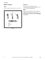
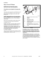
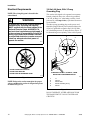
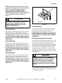
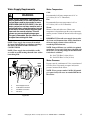
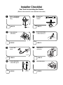
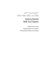
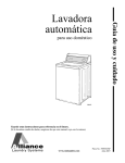
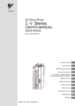
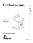
Installation
Automatic
Washers
Home Laundry
W001C
W001C
Keep These Instructions for Future Reference.
(If this machine changes ownership, this manual must accompany machine.)
www.comlaundry.com
Part No. 38900R8
April 2007
Table of
Contents
Replacement Parts ..............................................................................
3
Installation...........................................................................................
Roughing in Dimensions ......................................................................
Before You Start ...................................................................................
Tools ................................................................................................
Electrical ..........................................................................................
Water................................................................................................
Installing the Washer ............................................................................
Step 1: Remove the Shipping Brace and Shipping Plug..................
Step 2: Wipe Out Inside of Washtub ...............................................
Step 3: Connect Fill Hoses...............................................................
Step 4: Connect Drain Hose to Drain Receptacle ............................
Step 5: Position and Level the Washer ............................................
Step 6: Connect the Washer to Electrical Power .............................
Step 7: Add Water to the Washer ....................................................
Step 8: Check Lid Switch ................................................................
Step 9: Check Installation ................................................................
Electrical Requirements........................................................................
120 Volt, 60 Hertz, With 3 Prong Grounding Plug .........................
120 Volt/50 Hertz ............................................................................
240 Volt/50 Hertz ............................................................................
230 Volt/50 Hertz ............................................................................
240 Volt/60 Hertz ............................................................................
Earthing (Grounding) Instructions ...................................................
Water Supply Requirements .................................................................
Water Temperature ..........................................................................
Water Pressure .................................................................................
Risers................................................................................................
5
5
6
6
6
6
7
7
7
8
9
12
13
13
13
13
14
14
15
15
15
15
15
17
17
17
18
Installer Checklist................................................................ Back Cover
© Copyright 2007, Alliance Laundry Systems LLC
All rights reserved. No part of the contents of this book may be reproduced or transmitted in any form or by any
means without the expressed written consent of the publisher.
38900
© Copyright, Alliance Laundry Systems LLC – DO NOT COPY or TRANSMIT
1
Notes
2
© Copyright, Alliance Laundry Systems LLC – DO NOT COPY or TRANSMIT
38900
Replacement Parts
If replacement parts are required, contact the source
from which you purchased your washer, or contact:
Alliance Laundry Systems
Shepard Street
P.O. Box 990
Ripon, WI 54971-0990
Phone: (920) 748-3950
for the name and address of the nearest authorized
parts distributor.
38900
© Copyright, Alliance Laundry Systems LLC – DO NOT COPY or TRANSMIT
3
Notes
4
© Copyright, Alliance Laundry Systems LLC – DO NOT COPY or TRANSMIT
38900
Installation
Roughing in Dimensions
65 cm
(25.6 in.)
1 cm
(0.4 in.)
*102.2 cm (40.25 in.)
*134.6 cm (53 in.)
71.1 cm
(28 in.)
*91.4 cm (36 in.)
*109.2 cm (43 in.)
*73.7 cm (29 in.)
56.2 cm
(22.13 in.)
66 cm
(26 in.)
TLW2075N
*With leveling legs turned into base.
38900
© Copyright, Alliance Laundry Systems LLC – DO NOT COPY or TRANSMIT
5
Installation
Before You Start
Electrical
Tools
For most installations, the basic tools you will need
are:
2
Refer to serial plate for specific electrical
requirements. For more detailed information, refer to
section on Electrical Requirements.
Water
Washer needs two standard 19.1 mm (3/4 inch) water
supply faucets with a pressure between 138 and
827 kPa (20 to 120 pounds per square inch). For more
detailed information, refer to section on Water Supply
Requirements.
3
1
4
D074I
1
2
3
4
D074I
Wrench
Screwdriver
Pliers
Level
Figure 1
6
© Copyright, Alliance Laundry Systems LLC – DO NOT COPY or TRANSMIT
38900
Installation
Installing the Washer
Step 2: Wipe Out Inside of Washtub
NOTE: If the washer is delivered on a cold day
(below freezing), or is stored in an unheated room
or area during the cold months, do not attempt to
operate it until the washer has had a chance to
warm up.
Prior to first wash, use an all purpose cleaner, or a
detergent and water solution, and a damp cloth to
remove shipping dust from inside of washtub.
Step 1: Remove the Shipping Brace and
Shipping Plug
NOTE: Install dryer before washer. This allows
room for attaching exhaust duct.
Remove the shipping brace from under the lid. The
plastic shipping plug will be released from the base of
the washer when removing the cardboard base from
the washer.
W371I
Figure 3
1
2
TLW521N
1
2
Shipping Brace
Shipping Plug
Figure 2
NOTE: Do not tilt washer to front or sides when
moving.
The shipping brace and plug should be saved and must
be reinstalled whenever washer is moved or
transported to a new location. This will prevent
damage to washer components.
NOTE: Refer to your Operating Instructions for
reinstalling shipping brace and shipping plug.
38900
© Copyright, Alliance Laundry Systems LLC – DO NOT COPY or TRANSMIT
7
Installation
Step 3: Connect Fill Hoses
4
1
NOTE: Refer to section on Water Supply
Requirements before connecting fill hoses.
The appliance is to be connected to the water mains
using new hose-sets and old hose-sets should not be
reused.
Turn on the water supply faucets and flush the lines for
approximately two minutes to remove any foreign
materials that could clog the screens in the water
mixing valve.
NOTE: When installing in newly constructed or
renovated building, it is very important to flush the
lines since build-up may have occurred during
construction.
Remove the two plain rubber washers and two filter
screens from accessories bag, and install them
according to Figure 4.
NOTE: Check filter screens for debris or damage
annually. Clean or replace them if necessary.
COLD
HOT
2
Turn water on and check for leaks. If leaks are found,
retighten the hose couplings. Continue tightening and
rechecking until no leaks are found.
C
H
8
5
7
6
TLW1988N
1
2
3
4
5
6
7
8
IMPORTANT: Thread hose couplings onto valve
connections finger-tight, then approximately 1/4
turn with pliers. DO NOT cross thread or
overtighten couplings.
3
Filter Screen (Screen must be facing
outward)
Fill Hose
Rubber Washer (Plain)
Cold Water Connection
Hot Water Connection
Install this end of hose to valve connections
at rear of washer.
Install this end of hose to water supply
faucet. (Black colored coupling for metric)
Faucet
Figure 4
IMPORTANT: Hoses and other natural rubber
parts deteriorate after extended use. Hoses may
develop cracks, blisters or material wear from the
temperature and constant high pressure they are
subjected to.
All hoses should be checked on a yearly basis for
any visible signs of deterioration. Any hose showing
the signs of deterioration listed above should be
replaced immediately. All hoses should be replaced
every 5 years.
8
© Copyright, Alliance Laundry Systems LLC – DO NOT COPY or TRANSMIT
38900
Installation
Step 4: Connect Drain Hose to Drain
Receptacle
Standpipe Installation:
Remove the drain hose from its shipping position on
the rear of the washer by unhooking the hose from the
retainer clamp.
Remove the beaded tie-down strap from accessories
bag and place around standpipe and drain hose,
approximately 30 cm (12 inches) down from the top of
pipe and tighten strap to hold hose to standpipe. This
will prevent the drain hose from dislodging from drain
receptacle during use.
Place the hose into the standpipe.
Find the instructions, on the following pages, that are
appropriate for your type of drain receptacle
(standpipe, high standpipe, low standpipe, sink, wall,
or laundry tub). Follow these instructions to properly
install the drain hose.
IMPORTANT: Drain receptacle must be capable of
handling a minimum of 3.2 cm (1-1/4 inch) outside
diameter drain hose.
IMPORTANT: To prevent siphoning, do not place
any ribbed portion of the drain hose into the
standpipe.
1
1
2
2
5
30 cm
(12 in.)
19.44 cm
(36 in.)
RECOMMENDED
HEIGHT
4
3
TLW1961N
TLW1961N
1
2
3
4
W324I
1
2
Retainer Clamp
Standpipe Adapter
5
Ribbed Portion of Drain Hose
Standpipe Adapter
Tie-Down Strap
Standpipe 5.08 cm (2 in.) or 4 cm (1-1/2 in.)
Diameter
Drain Hose Sleeve
Figure 6
Figure 5
38900
© Copyright, Alliance Laundry Systems LLC – DO NOT COPY or TRANSMIT
9
Installation
High Standpipe Installation:
Low Standpipe Installation:
Place the hose into the standpipe. Remove the beaded
tie-down strap from accessories bag and place around
standpipe and drain hose, approximately 30 cm
(12 inches) down from the top of pipe and tighten
strap to hold hose to standpipe. This will prevent the
drain hose from dislodging from drain receptacle
during use.
No. 562P3 Siphon Break Kit is required for this type
of installation. This kit is available (as optional
equipment at extra cost) through an authorized dealer
or parts distributor. Installation instructions are
supplied with the kit.
1
1
4
3
3
W512I
2
W512I
1
2
3
562P3 Siphon Break Kit
Standpipe
Drain Hose
TLW1962N
Figure 8
2
TLW1962N
1
2
3
4
Drain Hose
Standpipe (Standpipes higher than 122 cm
[4 feet] are not recommended)
Tie-Down Strap
Standpipe Adapter
Figure 7
10
© Copyright, Alliance Laundry Systems LLC – DO NOT COPY or TRANSMIT
38900
Installation
Sink Installation:
In the Wall Installation:
For this type of installation, use the beaded tie-down
strap (supplied in accessories bag), or use a large wire
tie (available from your local hardware store) and
secure the drain hose to the cabinet top hinge. Refer to
Figure 9. This will prevent the drain hose from
dislodging during use.
For installations of this type, the drain hose MUST be
secured to one of the inlet hoses using the beaded tiedown strap from accessories bag.
1
NOTE: End of drain hose must not be below height
of cabinet top.
2
1
2
W329I
3
TLW1963N
1
2
3
Drain Hose
Tie-Down Strap or Wire Tie
Cabinet Top Hinge
1
2
Tie-Down Strap (Tape if necessary)
Standpipe Adapter
Figure 10
Figure 9
38900
© Copyright, Alliance Laundry Systems LLC – DO NOT COPY or TRANSMIT
11
Installation
Laundry Tub Installation:
Step 5: Position and Level the Washer
For this type of installation, the drain hose MUST be
secured to the stationary tub to prevent hose from
dislodging during use. Use the beaded tie-down strap
(supplied in accessories bag) to secure hose.
Position washer so it has sufficient clearance for
installation and servicing.
Place rubber feet on all four leveling legs.
Place washer in position on a clean, dry, and
reasonably firm floor. Installing the washer on any
type of carpeting is not recommended.
Loosen 7/8 inch locknuts and adjust the two front
leveling legs. Once adjusted, tilt the unit forward on
front legs and lower back down into position to set the
rear self-leveling legs.
Washer must not rock. After washer is at desired
height, tighten locknuts securely against bottom of
washer base. If these locknuts are not tight, washer
will not remain stationary during operation.
Improper installation or flexing of a weak floor will
cause excessive vibration.
1
TLW1964N
TLW1964N
1
Tie-Down Strap (Tape if necessary)
Figure 11
Do not slide washer across floor once the leveling legs
have been extended, as legs and base could become
damaged.
Verify that washer doesn’t rock.
1
5
2
4
3
W179I
1
2
3
4
5
Level
Locknut
Leveling Leg
Rubber Cup
Washer Base
Figure 12
12
© Copyright, Alliance Laundry Systems LLC – DO NOT COPY or TRANSMIT
38900
Installation
Step 6: Connect the Washer to Electrical
Power
Refer to section on Electrical Requirements and
connect the washer to an electrical power source.
Step 8: Check Lid Switch
Washer should stop agitating and spinning when lid is
opened.
W376IE0A
W376I
D254I
D254I
Figure 15
Figure 13
Step 9: Check Installation
Step 7: Add Water to the Washer
To prevent damage to pump, do not run washer before
adding at least one quart water to the tub. If the washer
is run before any water is added, the pump seal may
overheat causing the pump to leak. Once installed, the
water retained in the drain system from the previous
cycle will provide sufficient cooling to prevent pump
seal damage.
Refer to Installer Checklist on the back cover of this
manual and make sure that washer is installed
correctly.
NOTE: The agitator should not be removed except
for service. The washtub is designed to be selfcleaning.
W391I
W391I
Figure 14
38900
© Copyright, Alliance Laundry Systems LLC – DO NOT COPY or TRANSMIT
13
Installation
Electrical Requirements
120 Volt, 60 Hertz, With 3 Prong
Grounding Plug
NOTE: The wiring diagram is located in the
control hood.
This washer is designed to be operated on a separate
branch, polarized, three-wire, effectively grounded,
120 Volt, 60 Hertz, AC (alternating current), circuit
protected by a 15 ampere fuse, equivalent fusetron or
circuit breaker.
WARNING
To reduce the risk of fire, electric shock or
personal injury, all wiring and earthing
MUST conform with the latest edition of the
National Electrical Code, ANSI/NFPA 70,
and such local regulations as might apply. It
is the customer’s responsibility to have the
wiring, fuses and circuit breakers checked
by a qualified electrician to make sure your
home has adequate electrical power to
operate the washer.
The three-prong grounding plug on the power cord
should be plugged directly into a polarized three-slot
effectively grounded receptacle rated 110/120 Volts
AC (alternating current) 15 Amps. Refer to Figure 17
for determining correct polarity of the wall receptacle.
2
1
3
120 ± 12
V.A.C.
0 V.A.C.
W129
5
120 ± 12
V.A.C.
4
DO NOT OVERLOAD CIRCUITS
DO NOT USE ADAPTER
D009I
DO NOT USE AN EXTENSION CORD
STANDARD 120 VOLT, 60 HERTZ, 3 WIRE
EFFECTIVELY GROUNDED CIRCUIT
D009I
D090I
Figure 16
NOTE: Refer to the washer nameplate for proper
voltage and Hertz the washer is designed to operate
on. Refer to Figure 18.
1
2
3
4
5
L1
Ground
Neutral Side
Round Grounding Prong
Neutral
Figure 17
DO NOT OPERATE OTHER APPLIANCES ON
THE SAME CIRCUIT. DO NOT OVERLOAD
CIRCUITS!
14
© Copyright, Alliance Laundry Systems LLC – DO NOT COPY or TRANSMIT
38900
Installation
NOTE: Some models come without an electrical
plug installed. If washer is not hard wired (refer to
Figure 19), a suitable plug that meets local
electrical standards, including earthing
requirements, must be installed. Refer to the
washer nameplate for proper voltage and Hertz the
washer is designed to operate on. Refer to
Figure 18.
1
WARNING
W334I
To reduce the risk of electric shock or fire,
DO NOT use an extension cord or an
adapter to connect the washer to the
electrical power source.
W031
120 Volt/50 Hertz
This washer is designed to be operated on a separate
polarized three-wire, earth (grounded) 120 Volt,
50 Hertz, single-phase electrical circuit protected by a
15 ampere fuse, equivalent fusetron or circuit breaker.
DO NOT OPERATE OTHER APPLIANCES ON
THE SAME CIRCUIT WHEN THE WASHER IS
OPERATING.
240 Volt/50 Hertz
This washer is designed to be operated on a separate
polarized three-wire, earth (grounded) 240 Volt,
50 Hertz, single-phase electrical circuit protected by a
10 ampere fuse, equivalent fusetron or circuit breaker.
DO NOT OPERATE OTHER APPLIANCES ON
THE SAME CIRCUIT WHEN THE WASHER IS
OPERATING.
230 Volt/50 Hertz
This washer is designed to be operated on a separate
polarized three-wire, earth (grounded) 230 Volt,
50 Hertz single-phase electrical circuit protected by a
10 ampere fuse, equivalent fusetron or circuit breaker.
DO NOT OPERATE OTHER APPLIANCES ON
THE SAME CIRCUIT WHEN THE WASHER IS
OPERATING.
1
Nameplate
Figure 18
240 Volt/60 Hertz
This washer is designed to be operated on a separate
polarized three-wire, grounded 240 Volt, 60 Hertz,
single-phase electrical circuit protected by a
10 ampere fuse, equivalent fusetron or circuit breaker.
DO NOT OPERATE OTHER APPLIANCES ON
THE SAME CIRCUIT WHEN THE WASHER IS
OPERATING.
Earthing (Grounding) Instructions
The washer must be earthed (grounded). In the event
of malfunction or breakdown, earthing will reduce the
risk of electric shock by providing a path of least
resistance for electric current. The washer is equipped
with a cord having an equipment-earthing conductor.
Some models are also equipped with a three-prong
earthing plug. The washer must be plugged or hard
wired into an appropriate power source that is properly
installed and earthed in accordance with all local codes
and ordinances.
WARNING
Improper connection of the equipmentearthing conductor can result in a risk of
electric shock. Check with a qualified
electrician or service person if you are in
doubt as to whether the washer is properly
earthed.
W032
Do not modify the plug provided with the washer — if
it will not fit the outlet, have a proper outlet installed
by a qualified electrician.
38900
© Copyright, Alliance Laundry Systems LLC – DO NOT COPY or TRANSMIT
15
Installation
PLUG
HARD WIRED
W402I
W403I
W403I
W402I
NOTE: Electrical receptacle must be located so that it is easily accessible with machine in place. If machine is hard
wired, an intermediate shut-off box with a 3 mm gap is required to meet EN 60335-1, clauses 24.3 and 22.2 or 3.5 mm
gap is required to meet Standard IEC 60335-1, clauses 24.3 and 22.2. Gap is defined as the minimum contact
separation of each pole in the switch between the “ON” and “OFF” positions.
Figure 19
16
© Copyright, Alliance Laundry Systems LLC – DO NOT COPY or TRANSMIT
38900
Installation
Water Supply Requirements
Water Temperature
Cold:
WARNING
Recommended cold water temperature is 10° to
24° Celsius (50° to 75° Fahrenheit).
Under certain conditions, hydrogen gas
may be produced in a hot water system that
has not been used for two weeks or more.
HYDROGEN GAS IS EXPLOSIVE. If the hot
water system has not been used for such a
period and before using the washer, turn on
all hot water faucets and let the water flow
from each for several minutes. This will
release any accumulated hydrogen gas.
The gas is flammable. Do not smoke or use
an open flame during this time.
W029
NOTE: Water supply faucets must fit standard
19.1 mm (3/4 inch) female garden hose couplings.
DO NOT USE SLIP-ON OR CLAMP-ON
CONNECTIONS.
NOTE: Water supply faucets should be readily
accessible to permit turning them off when washer
is not being used.
1
2
Recommended hot water temperature is 60° to
66° Celsius (140° to 150° Fahrenheit).
Warm:
Mixture of hot and cold water. (Warm water
temperature is dependent upon the water temperature
and the pressure of both the hot and cold water supply
lines.)
IMPORTANT: Turn off water supply faucets after
check-out and demonstration. Owner should turn
off water supply whenever there will be an
extended period of non-use.
NOTE: Longer fill hoses are available (as optional
equipment at extra cost) if the hoses (supplied with
the washer) are not long enough for the installation.
Order hoses as follows:
No. 20617 Fill Hose 2.44 m (8 feet)
No. 20618 Fill Hose 3.05 m (10 feet)
Water Pressure
WATER
MIXING
VALVE
Pressure must be a minimum of 138 to a maximum of
827 kPa (20 to 120 pounds per square inch) static
pressure measured at the faucet.
NOTE: Water pressure under 138 kPa (20 pounds
per square inch) will cause an extended fill time in
the washer.
C
H
4
Hot:
3
W187I
1
2
3
4
Water Supply Faucets
Cold Water Connection
Hot Water Connection
Fill Hoses
Figure 20
38900
© Copyright, Alliance Laundry Systems LLC – DO NOT COPY or TRANSMIT
17
Installation
Risers
Risers (or air cushions) may have to be installed if the
pipes knock or pound when flow of water stops. The
risers are more efficient when installed as close as
possible to the water supply faucets. Refer to
Figure 21.
1
2
W005I
W005I
1
2
Risers (Air cushions)
Water Supply Faucets
Figure 21
18
© Copyright, Alliance Laundry Systems LLC – DO NOT COPY or TRANSMIT
38900
Installer Checklist
Fast Track for Installing the Washer
(Refer to the manual for more detailed information)
➊
CHECK
➋
➎
• Remove the Shipping
Brace and Shipping
Plug.
CHECK
TLW521N
➏
• Wipe Out Inside
of Washtub.
• Position and
Level the
Washer.
LEVEL
D255I
W316I
W316I
• Connect the Washer
to Electrical Power.
D254I
D254IE2A
W371IE0B
W371I
CHECK
CHECK
➌
• Connect Fill
Hoses.
➐
COLD
HOT
• Add Water to
the Washer.
C
H
TLW1988N
TLW1988N
TLW2056N
W391I
CHECK
CHECK
➍
➑
• Connect Drain Hose
to Drain Receptacle.
• Check Lid Switch.
W376I
W376IE0A
CHECK
W315IE0A
W315IE0A
CHECK