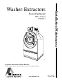
1
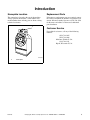
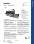
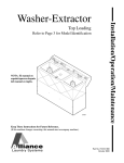
Installation/Maintenance
Washer-Extractors
Pocket Hardmount
WE-6 Control
UW50P-4
P031I
Keep These Instructions for Future Reference.
(If this machine changes ownership, this manual must accompany machine.)
www.comlaundry.com
Part No. F232158
September 2002
Table of
Contents
Introduction.........................................................................................
Nameplate Location..............................................................................
Replacement Parts ................................................................................
Customer Service..................................................................................
3
3
3
3
Safety Information..............................................................................
Important Safety Instructions ...............................................................
5
5
Installation...........................................................................................
Specifications and Dimensions.............................................................
Machine Foundation .............................................................................
Floor Load Data ...............................................................................
Mechanical Installation.........................................................................
Drain Connection..................................................................................
Water Connection .................................................................................
Electrical Installation ............................................................................
Input Voltage Requirements ............................................................
Connection Specifications ...............................................................
Electrical Connection Data ..............................................................
Grounding ........................................................................................
Phase Adder .....................................................................................
Control Function Test Procedure .....................................................
7
7
10
10
11
13
15
16
16
16
17
18
18
18
Maintenance ........................................................................................
General..................................................................................................
Daily .....................................................................................................
Monthly.................................................................................................
Care and Maintenance of Stainless Steel..............................................
Daily Preventive Maintenance Checklist..............................................
Weekly Preventive Maintenance Checklist ..........................................
Monthly Preventive Maintenance Checklist.........................................
Quarterly Preventive Maintenance Checklist .......................................
19
19
19
19
20
21
22
23
24
Removal from Service ........................................................................ 25
Decommissioning ................................................................................. 25
© Copyright 2002, Alliance Laundry Systems LLC
All rights reserved. No part of the contents of this book may be reproduced or transmitted in any form or by any
means without the expressed written consent of the publisher.
F232158
© Copyright, Alliance Laundry Systems LLC – DO NOT COPY or TRANSMIT
1
Notes
2
© Copyright, Alliance Laundry Systems LLC – DO NOT COPY or TRANSMIT
F232158
Introduction
Nameplate Location
Replacement Parts
The nameplate is located at the top of the machine.
Always provide the machine’s serial number and
model number when ordering parts or when seeking
technical assistance.
If literature or replacement parts are required, contact
the source from which the machine was purchased or
contact Alliance Laundry Systems at (920) 748-3950
for the name and address of the nearest authorized
parts distributor.
1
Customer Service
For technical assistance, call any of the following
numbers:
(850) 718-1025
(850) 718-1026
Marianna, Florida U.S.A.
(920) 748-3121
Ripon, Wisconsin U.S.A.
PHM516N
PHM516N
1
F232158
Nameplate
© Copyright, Alliance Laundry Systems LLC – DO NOT COPY or TRANSMIT
3
Notes
4
© Copyright, Alliance Laundry Systems LLC – DO NOT COPY or TRANSMIT
F232158
Safety Information
Precautionary statements (“DANGER,”
“WARNING,” and “CAUTION”), followed by
specific instructions, are found in this manual and on
machine decals. These precautions are intended for the
personal safety of the operator, user, servicer, and
those maintaining the machine.
DANGER
DANGER indicates the presence of a
hazard that will cause severe personal
injury, death, or substantial property
damage if the danger is ignored.
WARNING
WARNING indicates the presence of a
hazard that can cause severe personal
injury, death, or substantial property
damage if the warning is ignored.
CAUTION
CAUTION indicates the presence of a
hazard that will or can cause minor
personal injury or property damage if the
caution is ignored.
Additional precautionary statements (“IMPORTANT”
and “NOTE”) are followed by specific instructions.
IMPORTANT: The word “IMPORTANT” is used
to inform the reader of specific procedures where
minor machine damage will occur if the procedure
is not followed.
NOTE: The word “NOTE” is used to communicate
installation, operation, maintenance or servicing
information that is important but not hazard
related.
Important Safety Instructions
WARNING
To reduce the risk of fire, electric shock,
serious injury or death to persons when
using your washer, follow these basic
precautions:
W023E
1. Read all instructions before using the washer.
2. Refer to the GROUNDING INSTRUCTIONS in
the INSTALLATION manual for the proper
grounding of the washer.
3. Do not wash textiles that have been previously
cleaned in, washed in, soaked in, or spotted with
gasoline, dry-cleaning solvents, or other
flammable or explosive substances as they give
off vapors that could ignite or explode.
4. Do not add gasoline, dry-cleaning solvents, or
other flammable or explosive substances to the
wash water. These substances give off vapors that
could ignite or explode.
5. Under certain conditions, hydrogen gas may be
produced in a hot water system that has not been
used for two weeks or more. HYDROGEN GAS
IS EXPLOSIVE. If the hot water system has not
been used for such a period, before using a
washing machine or combination washer-dryer,
turn on all hot water faucets and let the water
flow from each for several minutes. This will
release any accumulated hydrogen gas. The gas is
flammable, do not smoke or use an open flame
during this time.
6. Do not allow children to play on or in the washer.
Close supervision of children is necessary when
the washer is used near children. This is a safety
rule for all appliances.
7. Before the washer is removed from service or
discarded, remove the door to the washing
compartment.
8. Do not reach into the washer if the wash drum is
moving.
F232158
© Copyright, Alliance Laundry Systems LLC – DO NOT COPY or TRANSMIT
5
Safety Information
9. Do not install or store the washer where it will be
exposed to water and/or weather.
10. Do not tamper with the controls.
11. Do not repair or replace any part of the washer, or
attempt any servicing unless specifically
recommended in the user-maintenance
instructions or in published user-repair
instructions that the user understands and has the
skills to carry out.
12. To reduce the risk of an electric shock or fire, DO
NOT use an extension cord or an adapter to
connect the washer to the electrical power source.
13. Use washer only for its intended purpose,
washing textiles.
14. ALWAYS disconnect the washer from electrical
supply before attempting any service. Disconnect
the power cord by grasping the plug, not the cord.
15. Install the washer according to the
INSTALLATION INSTRUCTIONS. All
connections for water, drain, electrical power and
grounding must comply with local codes and be
made by licensed personnel when required.
16. To reduce the risk of fire, textiles which have
traces of any flammable substances such as
vegetable oil, cooking oil, machine oil,
flammable chemicals, thinner or anything
containing wax or chemicals such as in mops and
cleaning cloths, must not be put into the washer.
These flammable substances may cause the
fabric to catch on fire by itself.
17. Do not use fabric softeners or products to
eliminate static unless recommended by the
manufacturer of the fabric softener or product.
18. Keep washer in good condition. Bumping or
dropping the washer can damage safety features.
If this occurs, have washer checked by a qualified
service person.
6
19. Replace worn power cords and/or loose plugs.
20. Be sure water connections have a shut-off valve
and that fill hose connections are tight. CLOSE
the shut-off valves at the end of each wash day.
21. Loading door MUST BE CLOSED any time the
washer is to fill, tumble or spin. DO NOT
bypass the loading door switch by permitting the
washer to operate with the loading door open.
22. Always read and follow manufacturer’s
instructions on packages of laundry and cleaning
aids. Heed all warnings or precautions. To reduce
the risk of poisoning or chemical burns, keep
them out of the reach of children at all times
(preferably in a locked cabinet).
23. Always follow the fabric care instructions
supplied by the textile manufacturer.
24. Never operate the washer with any guards and/or
panels removed.
25. DO NOT operate the washer with missing or
broken parts.
26. DO NOT bypass any safety devices.
27. Failure to install, maintain, and/or operate this
washer according to the manufacturer’s
instructions may result in conditions which can
produce bodily injury and/or property damage.
NOTE: The WARNINGS and IMPORTANT
SAFETY INSTRUCTIONS appearing in this
manual are not meant to cover all possible
conditions and situations that may occur. Common
sense, caution and care must be exercised when
installing, maintaining, or operating the washer.
Any problems or conditions not understood should be
reported to the dealer, distributor, service agent or the
manufacturer.
© Copyright, Alliance Laundry Systems LLC – DO NOT COPY or TRANSMIT
F232158
Installation
Specifications and Dimensions
Description
Stainless Steel
Cylinder
Frame (Note)
Shaft
Shell
Shell Door
Safety Interlock
Spray FlushRinse*
Bearings and
Seals
Suds Overflow
Connection
Drain Valve
Water Inlet
Valves
Automatic
Supply
Injection*
F232158
UW50 shall be a Heavy Duty Stainless Steel Open End. Open Pocket combination laundry washerextractor, equipped with standard deep rinse, plus through-the-door spray rinse which is capable of
rinsing during the extract cycle and producing up to three loads per hour. Machine shall have direct Vbelt drive without transmission, gears or variable-speed pulleys to reduce mechanical problems.
Type 304 corrosion resistant stainless steel must be used for the front panel, cylinder shell, shell door,
basket, side panels, control unit and top.
Cylinder size shall be 32 inch diameter by 18 inch depth. There shall be four lifters with a tie rod
through lifter being not less than 1/2 inch stainless steel. The cylinder shall have a full size steel back
plate not less than 1/2 inch in thickness.
The frame shall be heavy duty gamma A-type with main support sides being 9 inch channel steel. The
A face plates will be a minimum of 3/8 inch thickness. The frame base will be constructed of 4 inch
steel H beam. Various other supports will be of 2-1/2 inch x 2-1/2 inch x 1/4 inch angle and 2 inch x
1/2 inch flat steel.
The cylinder shaft shall be of AISI-C-1042 turned, ground and polished. It shall have a minimum
diameter of 2-7/16 inches.
The entire shell shall be of stainless steel, including all fittings and means of securing the shell. All
welds are heliarced.
The shell door shall be of stainless steel, suitably polished. The door opening shall be a minimum of
17-1/2 inches in diameter and door shall be fitted with a proper door gasket and a suitable operating
door handle. A circular door glass of specially treated high tensile strength glass capable of
withstanding high mechanical and thermal shock shall be provided.
The shell door shall have an interlock device which shall prevent operation of the machine until the
door is closed and locked. There shall also be a “fail safe” type of lock that will prevent the door from
being opened until the end of the cycle and also in case of loss of power to the machine.
The spray flush-rinse shall consist of a suitable hose of a minimum inside diameter of 3/4 inch, and
suitable fittings to introduce a spray through the center of the glass on the door.
The front and rear main bearings shall be self-aligning double row spherical roller bearings. Bearings
shall be installed in an adequate bearing housing which can be rigidly secured to the frame. Seal
design shall be of a mechanical face seal giving good protection against alkalis and acids. The seal
incorporates means to compensate for variation in shaft length due to expansion and contraction.
A 2 inch pipe size overflow connection will be provided.
The machine shall be equipped with a 2-1/2 inch pinch type gravity drain valve which will be open
with power removed.
The machine shall be equipped with two or four 1/2 inch (two hot and two cold) solenoid operated
inlet valves of heavy brass. The solenoid coils must be waterproof and mechanically protected.
A four-pocket supply injector shall automatically add washing supplies at correct time in formula.
Supply compartments shall be filled at beginning of each load. Supplies shall not be flushed into
washer until the proper water level has been reached.
© Copyright, Alliance Laundry Systems LLC – DO NOT COPY or TRANSMIT
7
Installation
Specification
UW50
Dimensions
Width
36 in. (915 mm)
Depth
40 in. (1015 mm)
Height
63 in. (1600 mm)
Weight
Net
1350 lbs. (612 kg)
Gross
1410 lbs. (640 kg)
Cylinder
Volume
8.40 cu. ft. (238 l)
Diameter
32 in. (810 mm)
Depth
18 in. (457 mm)
Wash Speed
44 RPM
Drain Speed
73 RPM
Medium Speed
350 RPM
Extract Speed
700 RPM
G-Factor Extract
222
Motor Power
Wash Speed
0.60 HP (0.45 kW)
Drain Speed
0.75 HP (0.56 kW)
Medium Speed
3.0 HP (2.2 kW)
Extract
3.5 HP (2.6 kW)
Motor Speed
Wash Speed
360 RPM/60 Hertz
290 RPM/50 Hertz
Extract Speed
3350 RPM/60 Hertz
2780 RPM/50Hertz
Water Connect
Size
3/4 in. (DN20)
Operating Pressure
10-120 psi (0.5-8 bar)
Recommended Pressure
30-85 psi (2-6 bar)
Maximum Temperature
200°F (90°C)
Steam Connect
Size
1/2 in. NPT
(DN15 mm)
Maximum Pressure
120 psi (8 bar)
Drain Connect
I.D. Size
3 in. (75 mm)
90.15 cu. ft. (2.55 m3)
Shipping Volume
Table 1
8
© Copyright, Alliance Laundry Systems LLC – DO NOT COPY or TRANSMIT
F232158
Installation
36 in.
(915 mm)
40 in.
(1016 mm)
63 in.
(1600 mm)
1 in.
(25 mm)
28.5 in.
(725 mm)
35.62 in.
(905 mm)
36 in.
(915 mm)
56 in.
(1420 mm)
15.5 in.
(395 mm)
PHM517N
F232158
© Copyright, Alliance Laundry Systems LLC – DO NOT COPY or TRANSMIT
9
Installation
Machine Foundation
A base designed to elevate the UW50 to a comfortable
and more accessible height for loading and unloading
laundry may be used. Care must be exercised in the
design of such a base due to the force exerted by the
machine during extract (222 Gs).
The machine must be secured to a foundation or floor
of adequate construction. Detail must be stressed with
all foundation work to ensure a stable unit installation,
eliminating possibilities of excessive vibration. The
machine must be anchored to a smooth level surface so
that the entire base of the machine is supported and
rests on the mounting surface. Do not support the
machine on only four points. Anchor bolts must be a
minimum of 3/4 inch diameter, grade 2. Refer to
Mechanical Installation.
Static and dynamic loads on the floor or foundation are
shown in Table 2. This table can be used as a reference
when designing floors and foundations.
NOTE: Machine must be installed on concrete floor
that is a minimum of 12 inches thick. Do not mount
on wooden floors. Do not install above ground floor.
Floor must be solid.
Floor Load Data
Model
UW50-4
Maximum Floor Load Frequency of
Dynamic
at Extraction Speed
Load
Combined Static and Dynamic
Floor Load
Mounting Bolt Size
lbs.
kN
Cycles (Hz)
lbs.
kN
lbs./
sq. ft.
kN/m2
inch
mm
1575±2220
7.0±9.9
11.67
3795
16.9
425.9
20.39
3/4
M20
Table 2
10
© Copyright, Alliance Laundry Systems LLC – DO NOT COPY or TRANSMIT
F232158
Installation
Mechanical Installation
1
A proper foundation is absolutely necessary for the
UW50P-4 due to its high extract speed and the G-force
exerted.
2
A bolt kit is available as an option consisting of eight
3/4 inch bolts, 8 inches long, which should be
imbedded in a reinforced concrete floor that is a
minimum of 12 inches thick.
3
4
0.75 in.
(19 mm)
1
2
5
3
2 in.
(51 mm)
PHM179N
TYPICAL METHOD OF MOUNTING
USING BASE FRAME
8 in.
(203 mm)
PHM179N
4
5
TYPICAL METHOD OF MOUNTING USING
INDIVIDUAL MOUNTING BOLTS
1
2
3
4
5
Machine Base
Bolt Threads
Grouting – 1/2 in. Thick
Reinforcing Rod
3/4 in. x 8 in. Bolt
Figure 2
PHM178N
NOTE: Existing floor must be a minimum of 12 inches
thick.
1
2
3
4
5
Machine Base
Piece of Angle Welded to Bolt to Prevent
Turning
Grouting – 1/2 in. Thick
3/4 in.-10 x 8 in. Bolt
Conical hole drilled or chiseled into existing
floor. Fill with “Sulfaset” bolt or equivalent.
Figure 1
The threaded end of the bolts should extend 2 inches
above the surface of the floor. Refer to Figure 3 for the
location of these bolts. A bolt locator fixture (base
frame), consisting of a rigid welded assembly made of
reinforcing rod welded to the eight 3/4 inch bolts
which may be embedded in the concrete as one piece
is also available as an option. Refer to Figure 2. Be
sure the bolt threads also extend 2 inches above the
floor.
F232158
© Copyright, Alliance Laundry Systems LLC – DO NOT COPY or TRANSMIT
11
Installation
0.75 in.
(19 mm)
34.12 in.
(867 mm)
0.75 in.
(19 mm)
4.81 in.
(122 mm)
44.81 in.
(1138 mm)
1.25 in.
(32 mm)
9 in.
(229 mm)
10.75 in.
(273 mm)
39.25 in.
(997 mm)
34.56 in.
(878 mm)
36 in.
(914 mm)
10.69 in.
(271 mm)
PHM518N
FRONT
2 in.
(51 mm)
X = 5 FEET
31.62 in.
(803 mm)
2 in.
(51 mm)
35.62 in.
(905 mm)
0.75 in.
(19 mm)
Figure 4
MOUNTING BOLT LAYOUT
PHM191N
Figure 3
PHM518N
If the existing floor is not reinforced concrete a
minimum of 12 inches thick over a solid base, it will
be necessary to cut a hole through existing floor
approximately 5 feet square and excavate to a depth of
36 inches from top of existing floor. Slope the edges of
the hole outwards so that the hole is pyramid shaped.
Excavate under existing floor 5 inches beyond the
required 5 feet square all around. Refer to Figure 4
where x = 5 feet.
Refill with 24 inches of well compacted clean fill dirt
topped with 12 inches of reinforced concrete. Imbed
mounting bolts or base frame when pouring concrete.
Make sure that the bolt threads extend 2 inches above
the floor level.
After the foundation for the machine has been
prepared and the concrete has cured, proceed as
follows:
1. Place the machine adjacent to the foundation. Do
not attempt to move the machine by pushing on
the sides. Always use a pry bar or other device at
the bottom of the machine. Remove the wood
skid.
12
© Copyright, Alliance Laundry Systems LLC – DO NOT COPY or TRANSMIT
F232158
Installation
Drain Connection
Providing an adequate drain arrangement and capacity
is essential. Ideally, the machine should dump through
a 3 inch pipe directly into a sump or floor drain.
11.63 in.
(295 mm)
35.75 in.
(908 mm)
27.63 in.
(702 mm)PHM518N
12.13 in.
(308 mm)
4 in. TYP.
(102 mm)
Connection to a drain must be vented to prevent an airlock or siphon effect and must be flexible. Increasing
drain hose length, installing elbows or causing bends
will decrease drain flow rate which might harm washer
performance. If the drain arrangement is inadequate,
the machine will not extract properly nor will it
discharge all the water. If proper drain line size is not
available or practical, a surge tank of adequate design
would be required.
35.63 in.
(905 mm)
1
GROUTING DIAGRAM – APPLY GROUT IN ALL
SHADED AREAS UNDER FRAME MEMBERS.
PHM519N
REMOVE COVER PANELS FOR ACCESS.
2
PHM519N
Figure 5
2. Set machine over bolts and shim the machine so
that it sits level and is 1/2 inch off the floor.
Apply machine grout between the floor and all
frame members of the base of the machine
(remove front panel and expanded metal back
panel to gain access to all frame members). Force
grout under machine base until all voids are
filled. Refer to Figure 5.
3
4
Leave a small opening for water drainage at the
rear of the machine. Do not omit this step.
3. After grout has cured, place washers and nuts on
bolts and tighten securely. Be sure nuts are
tightened evenly all around. DO NOT DISTORT
MACHINE BY BOLTING DOWN ON AN
UNEVEN FLOOR SURFACE.
NOTE: Make sure to retighten the anchor bolts
after a few days of operation.
PHM528N
1
2
3
4
Rear of Machine
Drain Assembly
Waste Line Tee – 3 in. Minimum
Waste Line – 4 in. Minimum
Figure 6
F232158
© Copyright, Alliance Laundry Systems LLC – DO NOT COPY or TRANSMIT
13
Installation
1
2
1
17 in.
(430 mm)
21 in.
(530 mm)
2
7 in.
(180 mm)
4
3
3
4
TOP VIEW
PHM520N
5
6
TYPICAL TROUGH DRAIN ARRANGEMENT
PHM183N
PHM183N
1
2
3
4
5
6
PHM520N
1
2
3
4
Steam Inlet Connection – 1/2 in. NPT
Drain Connection 3 in. PVC
Water Inlet Connection – 3/4 in. NPT
Door Open
Figure 8
Rear of Machine
Drain Assembly
Steel Grate
Drain Trough
Strainer
Waste Line
Figure 7
A surge tank should also be used in conjunction with a
sump pump when gravity drainage is not possible.
At the rear of the machine, on a centerline
15-1/2 inches from the floor, is a 3 inch PVC pipe
connection for the drain. Drainage is by gravity.
14
© Copyright, Alliance Laundry Systems LLC – DO NOT COPY or TRANSMIT
F232158
Installation
Water Connection
Separate hot and cold plumbing lines (3/4 inch pipe or
larger) with individual shut-off valves must be
provided. Hot water should be a minimum of 160°F.
Best performance will be realized if water is provided
at a pressure of 30-85 psi. Although the machine will
function properly at a lower pressure, excessive fill
times will occur.
Use flexible hoses or equivalent flexible lines. The
hoses should hang in a large loop. Do not allow to
kink.
Flush the water system and check filters in machine
inlet hoses for proper fit and cleanliness before
connecting.
Each of the hoses should have a screen filter installed
to keep rust and other foreign particles out of the
solenoid valves. These connections should be supplied
by a hot and a cold water line at least 3/4 inch size for
each. Installation of additional washers will require
proportionately larger water lines. Refer to Table 3.
Suitable air cushions should be installed in supply
lines to prevent “hammering.” If the water pressure is
above 60 psi, flexible copper tubing should be used in
place of the rubber hoses.
Water and Drain Line Requirements
Number of
Machines
Pipe Sizes
Minimum Drain
1
3/4 in.
3 in. I.D.
2
1-1/4 in.
4 in. I.D.
3
1-1/2 in.
5 in. I.D.
4
1-1/2 in.
5 in. I.D.
5
2 in.
6 in. I.D.
The UW50 has a total of four hose connections. Each
pair of hoses is connected to a hot and cold water
faucet with a 3/4 inch hose bib. Each machine requires
incoming water connections as follows:
Four 3/4 inch faucets with 3/4 inch hose bib
connected to two 3/4 inch hot water faucet lines and
two 3/4 inch cold water faucet lines.
Table 3
1
1
2
Y041I
2
Y041I
1
2
3/4 in. Cold Water Supply Line
3/4 in. Faucet Lines
Figure 9
PHM184N
PHM184N
1
2
Risers (Air Cushions)
Water Supply Faucets
Figure 10
F232158
© Copyright, Alliance Laundry Systems LLC – DO NOT COPY or TRANSMIT
15
Installation
Electrical Installation
Use wire sizes indicated in the Electrical Specifications
chart for runs up to 50 feet (15 m). Use next larger size
for runs of 50 to 100 feet (15 to 30 m). Use two sizes
larger for runs greater than 100 feet (30 m).
WARNING
Hazardous Voltage. Can cause shock,
burn or cause death. Allow machine
power to remain off for two minutes prior
to working in and around AC inverter
drive.
The UW50 is provided with a thermal overload
protector in the drive motor windings and a separate
fuse for the control circuit. However, a separate threephase circuit breaker must be installed for protection
against shorts. DO NOT USE FUSES.
W359
WARNING
Hazardous Voltage. Can cause shock,
burn or death. Verify that a ground wire
from a proven earth ground is connected
to the lug near the input power block on
this machine.
For proper over current protection, the circuit breaker
should be a 30 Amp capacity unit rated for
208-240 Volts and should be a three-phase breaker so
that in the event that one leg should be removed from
the machine, all three legs will be disconnected to
prevent damage to the motor.
WARNING
W360
Input Voltage Requirements
If input voltage measures above 240 Volt for a
200 Volt drive or above 440 Volt for a 400 Volt
drive, ask the power company to lower voltage.
For voltages above or below listed specifications,
contact Customer Service or a distributor for buck/
boost transformer recommendation.
If machine is intended for four-wire service, a neutral
leg must be provided by power company.
If a delta supply system is used on a four-wire model,
connect high leg to L3.
IMPORTANT: Improper connections will result in
equipment damage and will void warranty.
Connection Specifications
IMPORTANT: Connection must be made by a
qualified electrician using wiring diagram provided
with machine, or according to accepted European
standards for CE-approved equipment.
Turn off power and water before
attempting any maintenance, repairs, or
service, or before opening any service
panel or door. This machine must be
connected and grounded in accordance
with the National Electric Code and/or any
other applicable code.
W448
The wire for the service connection should be a
minimum size of 8 gauge (AWG) for 208-240 Volt
installations. Refer to Table 7.
The connections should be made by a qualified
electrician and in accordance with the wiring diagram
provided with the machine.
When the machine is started, check that the cylinder
rotates in the correct direction during the spin (extract)
step, i.e., clockwise as seen from the front of the machine.
If the machine rotates in the wrong direction, two of
the lines are to be interchanged at the power connection
terminal (reverse L1 and L2 – do not reverse L3).
Connect machine to an individual branch circuit not
shared with lighting or other equipment. Shield
connection in a liquid-tight or approved flexible
conduit. Proper conductors of correct size must be
installed in accordance with National Electric Code or
other applicable codes.
16
© Copyright, Alliance Laundry Systems LLC – DO NOT COPY or TRANSMIT
F232158
Installation
Electrical Connection Data
Model
Volt
Phase
Cycle
Max. Amps
UW50
240
3
60
13
White
N
Red
T (L3)
Blue
S (L2)
Black
R (L1)
TO CONTROL
MODULE
Table 4
Circuit Breaker
Wire Size
30 Amp
8 AWG
Table 5
For Machines with Other Voltages
Volt
Max. Amps Wire Size Circuit Breaker
440-480
8
10 AWG
25 Amp
380-415
8
10 AWG
25 Amp
1
J-BOX MOUNTED ON REAR OF CONTROL MODULE
PHM185N
1
Ground Lug Connect to Proven Earth Ground
Table 6
Figure 11
For Machines with Electric Heat
Volt
Max. Amps Wire Size Circuit Breaker
220
65
6 AWG
70 Amp
380-415
37
8 AWG
40 Amp
Table 7
Use wire size indicated in Table 7 for runs up to
50 feet. Use next larger size for runs of 50-199 feet.
Use two sizes larger for runs greater than 100 feet.
This protects against voltage drop which would result
in a reduction of starting toque.
Electrical connections are made at the J-box located on
the rear of the control module. The machine must be
connected to the proper electrical supply shown on the
identification plate attached to the side of the control
module.
F232158
Do not connect the ground to the neutral (N-white
wire) leg at the J-box terminal strip. If the machine is
intended for 4 wire service, a neutral leg must be
provided by the power company. Do not connect the
neutral leg to the ground lug.
If a Delta Supply System is used, the high leg must be
connected to the red wire (L3) at the J-box terminal
strip. If three-phase service is not available and a RotoPhase or other phase adder is used, the artificial leg
must be connected to the red wire (L3).
Improper connections will result in equipment damage
and will void the warranty. It is your responsibility to
have all electrical connections made by a properly
licensed and competent electrician. assure that the
electrical installation is adequate.
Rotation should be clockwise in spin. To change
direction of rotation, interchange the black (L1) and
blue (L2) leads.
© Copyright, Alliance Laundry Systems LLC – DO NOT COPY or TRANSMIT
17
Installation
Grounding
3. Turn on electric power.
For personal safety and proper operation, the machine
must be grounded in accordance with state and local
codes. If such codes are not available, grounding must
conform to the National Electric Code, article 250-95.
The ground connection must be made to a proven earth
ground, not to conduit or water pipes.
4. Select Cycle 01 by pressing “0” and “1” on the
keyboard and press START.
Do not connect ground to neutral (N-white wire) leg at
J-box terminal strip.
Phase Adder
If three-phase service is unavailable for a 2 speed
model and a Roto-Phase or other phase adder is used,
connect artificial leg to L3 in input power junction
box.
IMPORTANT: Do not use a phase adder on any
variable-speed machine.
Control Function Test Procedure
In the machine, you will find the warranty registration
card, the wiring diagram and other pertinent material.
The warranty card should be filled out and returned to
Alliance Laundry Systems. The other material should
be removed and put in a safe place for future reference
as needed.
5. To fast advance through the test cycle, press the
ADVANCE key (drain steps must be allowed to
complete).
6. Check the door interlock by opening the loading
door (press and hold the door unlock button) and
attempt to start the machine in the normal
manner. The machine must not start while the
door is open.
Close the door without fully locking it. Attempt
to start the machine. The machine must not start
without the door being fully closed and fully
locked.
Close and lock the door and start the machine.
Attempt to open the door while the machine is
operating. The door must remain locked and can
not be opened while the machine is operating.
7. Run a complete cycle and check operation of
water inlet valves, drain and spin (extract)
functions.
8. Rotation must be clockwise in spin (extract) step.
If not, reverse line L1 and l2 at the J-box.
The machine should be cleaned when the installation
is completed, and a function test executed without a
load in the machine as follows:
1. Check power supply for correct characteristics as
to voltage, phase and cycles to be sure they are
correct for the machine.
2. Open manual water shut-off valves to the
machine.
18
© Copyright, Alliance Laundry Systems LLC – DO NOT COPY or TRANSMIT
F232158
Maintenance
General
Monthly
This section covers preventive maintenance. Even if
preventive maintenance has been reduced to a
minimum by the careful design of this machine and the
choice of components, it is necessary to maintain and
keep the machine clean. This will prolong the life of
the machine and avoid hours of probable service.
Daily
1. Check V-belt for wear, proper tension and
alignment.
2. Check motor mounting bolts and clean lint from
motor.
3. Check all water connections and hose
connections for leaks. Tighten or replace as
needed.
1. Check door lock and interlock before starting
operation.
4. Remove and clean water inlet valve and hose
screen filters. Replace if worn or damaged.
2. Clean automatic supply dispenser and lid inside
and out with mild detergent. Rinse with clean
water.
5. Check anchor bolts – tighten if necessary.
3. Clean the shell, front and side panels with mild
detergent. Rinse with clean water.
4. Check drain for leaks and proper opening.
5. Check loading door for leaks. Clean the door seal
of all foreign matter.
6. Leave loading door open to air out the machine at
the end of the cycle and at the end of the day.
WARNING
Before performing any maintenance,
make sure that the main power to the
machine is switched off and locked out.
W449
6. Wipe clean the inside of the washer and check
that all electrical components are free of moisture
and dust.
IMPORTANT: Replace any and all panels that
were removed to perform daily or monthly
maintenance.
CAUTION
To help avoid personal injury, take care
when doing any maintenance or making
any check or repair. Follow
manufacturer’s instructions for all
materials used during service and
maintenance of this machine. If used or
handled improperly, they can be
hazardous. Improper or incomplete
service can also affect the machine and
result in personal injury, or damage to the
machine and may void the warranty. If you
have any question about carrying out
some service, have the work done by a
skilled technician.
W450
F232158
© Copyright, Alliance Laundry Systems LLC – DO NOT COPY or TRANSMIT
19
Maintenance
Care and Maintenance of Stainless
Steel
The following points on the care and maintenance of
stainless steel surfaces should be observed in order to
maintain the natural beauty and prolong its service
life.
1. Cleanliness is of utmost importance. Common
deposits of dirt and grease can be quickly
removed with a detergent and water solution.
Whenever possible, the metal should be
thoroughly rinsed and dried after washing.
Periodic cleaning will maintain the bright surface
appearance and help prevent corrosion.
2. Deposits that adhere to the surface of the
stainless steel should be removed especially from
crevices and corners. When using abrasive
cleaners, always rub in the direction of the polish
lines or “grain” of the stainless steel to avoid
scratch marks showing. Never use ordinary steel
wool or steel brushes on stainless steel. Iron
particles from steel wool and brushes made of
carbon steel may become imbedded in the
surface, causing rust. Use stainless steel wool or
soft non-metal bristle brushes.
3. Contact with dissimilar metals should be avoided
whenever possible. This will help prevent
galvanic corrosion when salty or acidic solutions
are present.
4. Discolorations or heat tint from overheating may
be removed by scouring with a powder or by
employing special chemical solutions.
5. Salty or acidic solutions should not be allowed to
evaporate and dry on stainless steel. They may
cause corrosion. Wash off the solution after
using.
6. Permanent direct contact with other materials,
such as wood or carbon steel, should be avoided.
7. Sanitizers or sterilizing solutions should not be
left in stainless steel equipment for prolonged
periods of time. These solutions often contain
chlorine which may cause pitting corrosion. The
stainless should be cleaned and rinsed thoroughly
after using.
8. Rust appearing on stainless steel sometimes leads
to the belief that the stainless is rusting. The
source of the rust may actually be some iron or
steel part not made of stainless, such as a nail or
screw. One remedy is to paint all carbon steel
parts with a heavy protective coating. Stainless
steel fasteners should be employed whenever
possible.
CAUTION
Follow the manufacturer’s advice
whenever cleaning agents or other
chemicals are used, inside or outside the
machine. Some cleaners may be
poisonous or flammable, and improper
use may cause personal injury or
damage. Do not use volatile cleaning
solvents such as acetone, lacquer
thinners or enamel reducers. Never use
carbon tetrachloride, gasoline, benzene
or naptha for any cleaning purpose.
W451
20
© Copyright, Alliance Laundry Systems LLC – DO NOT COPY or TRANSMIT
F232158
Maintenance
Daily Preventive Maintenance
Checklist
Week Of:
Machine ____________________________
Operator
________________
Days
___________________________
Checks
1
2
3
4
5
6
7
Observe All Safety Warnings!
Disconnect power to the washer-extractor before performing the
daily maintenance procedures.
Beginning of Day
1. Inspect water inlet valve hose connections on the back of the
washer-extractor for leaks.
2. Inspect steam hose connections for leaks (where applicable).
3. Verify that insulation is intact on all external wires and that all
connections are secure.
4. Check door lock and interlock before starting operation:
a. Attempt to start the washer-extractor with door open.
b. Close the door without locking it and attempt to start the
washer-extractor.
c. Close and lock the door, start a cycle, and attempt to open the
door while the cycle is in progress.
End of Day
1. Clean the AC drive box filters.
2. Clean the door gasket of all foreign matter.
3. Clean automatic supply dispenser and lid.
4. Clean the washer-extractor’s top, front, and side panels.
5. Leave loading door open at the end of each day to allow moisture
to evaporate.
NOTE: Unload the washer-extractor promptly after each completed cycle to prevent moisture buildup.
NOTE: Leave loading door open after each completed cycle to allow moisture to evaporate.
F232158
© Copyright, Alliance Laundry Systems LLC – DO NOT COPY or TRANSMIT
21
Maintenance
Weekly Preventive Maintenance
Checklist
Machine ____________________________
Operator
Month __________
Week Ending:
___________________________
Checks
/
/
/
/
/
Observe All Safety Warnings!
Disconnect power to the washer-extractor before performing the
weekly maintenance procedures.
1. Check the washer-extractor for leaks:
a. Start an unloaded cycle to fill the washer-extractor.
b. Verify that door and door gasket do not leak.
c. Verify that the drain valve is operating.
2.
3.
4.
5.
6.
7.
22
© Copyright, Alliance Laundry Systems LLC – DO NOT COPY or TRANSMIT
F232158
Maintenance
Monthly Preventive Maintenance
Checklist
Machine ____________________________
Operator
Month
___________________________
Checks
Observe All Safety Warnings!
Disconnect power to the washer-extractor before performing the
monthly maintenance procedures.
1. Each month OR after every 200 hours of operation, lubricate bearings.
2. Clean the AC drive fins.
3. Determine if V-belts require replacement or adjustment:
a. Check V-belts for uneven wear and frayed edges.
b. Verify that V-belts are properly tensioned.
c. Verify that V-belts are properly aligned.
4. Remove back panel and check hoses for leaks.
5. Unlock the hinged lid and check supply dispenser hoses and connections.
6. Clean inlet hose filter screens. Replace if worn or damaged.
7. Tighten motor mounting bolt locknuts and bearing bolt locknuts, if necessary.
8. Use compressed air to clean lint from motor.
9. Clean interior of washer-extractor, both basket and shell, by wiping with a
water-soaked sponge or cloth.
10. Use compressed air to clean moisture and dust from all electrical components.
11.
12.
13.
14.
F232158
© Copyright, Alliance Laundry Systems LLC – DO NOT COPY or TRANSMIT
23
Maintenance
Quarterly Preventive Maintenance
Checklist
Machine ____________________________
Operator
Quarter
___________________________
Checks
Observe All Safety Warnings!
Disconnect power to the washer-extractor before performing the
quarterly maintenance procedures.
1. Tighten door hinges and fasteners, if necessary.
2. Tighten anchor bolts, if necessary.
3. Verify that the drain motor shield is in place and secure.
4. Check all painted surfaces for bare metal. Repair, if necessary.
5. Clean steam filter, if applicable.
6.
7.
8.
9.
10.
11.
24
© Copyright, Alliance Laundry Systems LLC – DO NOT COPY or TRANSMIT
F232158
Removal from Service
Decommissioning
In the event that the machine must be
decommissioned, follow these steps:
1. Clean interior of machine, both basket and shell.
5. Remove the machine from its foundation pad.
a. Keep all panels in place to provide stability
when moving the machine.
b. Verify that door is closed and secure.
a. Flush supply system with water.
c. Loosen and remove the mounting bolts.
b. Run a short rinse cycle to clean detergent and
chemical residues from the interior of the
machine.
d. Break the grout seal at each corner of the
machine, using a crowbar.
2. Disconnect electrical power.
a. Shut off main power supply at the breaker box
or main control panel.
b. Have a qualified electrician disconnect power
to the machine at its source.
3. Disconnect hoses.
a. Disconnect drain hose from sump, gutter, or
drain.
e. Use crowbars at the front corners to lift the
machine a few inches so that the forks of a
forklift truck can reach under the machine.
f. Bolting the base frame to a pallet will
facilitate removal to a transport vehicle.
6. Recycle.
Alliance Laundry Systems uses the highest
quality materials in their products so that those
materials may be recycled at the end of the
product’s service life.
b. Turn off water supply. Disconnect individual
hot and cold water inlet hoses from the
machine.
c. Allow time for residual water in the machine
to drain. Then disconnect drain hose from the
machine.
4. Disconnect steam hoses, if applicable.
a. Turn off steam supply and allow time for the
valves to cool.
b. Disconnect steam hoses from machine.
F232158
© Copyright, Alliance Laundry Systems LLC – DO NOT COPY or TRANSMIT
25
Notes
26
© Copyright, Alliance Laundry Systems LLC – DO NOT COPY or TRANSMIT
F232158