1
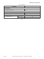
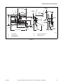
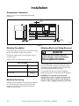
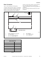
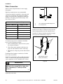
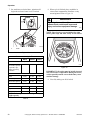
Installation/Operation/Maintenance
Washer-Extractor
Twin Tub
UM202
Design 3 Models
CAR4C
Keep These Instructions for Future Reference.
(If this machine changes ownership, this manual must accompany machine.)
www.comlaundry.com
Part No. F8221501R1
January 2012
Table of
Contents
Introduction........................................................................................
Model Identification .............................................................................
Nameplate Location..............................................................................
Replacement Parts ................................................................................
Customer Service..................................................................................
2
2
2
2
2
Safety Information..............................................................................
Explanation of Safety Messages...........................................................
Important Safety Instructions ...............................................................
Safety Decals ........................................................................................
Operator Safety.....................................................................................
4
4
4
6
7
Specifications and Dimensions...........................................................
8
Installation...........................................................................................
Dimensional Clearances .......................................................................
Machine Foundation .............................................................................
Machine Anchoring ..............................................................................
Shipping Block and String Removal ....................................................
Electrical Installation ............................................................................
Input Voltage Requirements ............................................................
Connection Specifications ...............................................................
Grounding ........................................................................................
Phase Adder .....................................................................................
Thermal Overload Protector ............................................................
Circuit Breakers ...............................................................................
Drain Connection..................................................................................
Water Connection .................................................................................
Control Function Test ...........................................................................
12
12
12
12
12
13
13
13
14
14
14
14
15
16
17
Operation............................................................................................. 18
Control Panel ........................................................................................ 18
Operating Instructions .......................................................................... 19
Maintenance ........................................................................................
Daily .....................................................................................................
Weekly..................................................................................................
Monthly.................................................................................................
Care of Stainless Steel ..........................................................................
22
22
22
22
23
© Copyright 2012, Alliance Laundry Systems LLC
All rights reserved. No part of the contents of this book may be reproduced or transmitted in any form or by any
means without the expressed written consent of the publisher.
F8221501
© Copyright, Alliance Laundry Systems LLC – DO NOT COPY or TRANSMIT
1
Introduction
Model Identification
Replacement Parts
Information in this manual is applicable to this model:
If literature or replacement parts are required, contact
the source from which the machine was purchased or
contact Alliance Laundry Systems LLC at (920) 748-3950
for the name and address of the nearest authorized
parts distributor.
UM202*
* This manual applies to models with U3 in the 9th and 10th
positions in the model number (e.g. UM202M1OU30001).
Customer Service
Nameplate Location
The nameplate decal is located at the rear of the
machine. Always provide the machine’s serial number
and model number when ordering parts or when
seeking technical assistance.
For technical assistance, call (920) 748-3121.
1
CAR19N
1
Nameplate
Figure 1
2
© Copyright, Alliance Laundry Systems LLC – DO NOT COPY or TRANSMIT
F8221501
Introduction
Model Number Familiarization Guide
Sample Model Number: UM202M1OU30001
UM
Model Number Prefix
202
Washer-Extractor
M
Type of Electrical Control
1
Washer-Extractor Speed Capability (1 = 1 speed)
O
Electrical Characteristics
U3
Design Series
0001
Option Identification (varies from machine to machine)
UM202M1OU30001
SERIAL NO: XXXXXXXXX
VOLTAGE: 208 – 240
HZ: 60
MODEL NO:
NUMBER OF WIRES:
MAX LOAD:
24 lbs
amps
FLA:
CIRCUIT BREAKER SIZE:
PHASE: 3
Ripon, WI 54971 U.S.A.
amps
11 kg
SCHEMATIC:
SUPPLY WATER:
30 – 85 psi,
2 – 5.7
bar
EXAMPLE OF NAMEPLATE
CAR18N
CAR18N
Figure 2
F8221501
© Copyright, Alliance Laundry Systems LLC – DO NOT COPY or TRANSMIT
3
Safety Information
Explanation of Safety Messages
Important Safety Instructions
Precautionary statements (“DANGER,” “WARNING,”
and “CAUTION”) followed by specific instructions
are found in this manual and on machine decals. These
precautions are intended for the personal safety of the
operator, user, servicer, and those maintaining the
machine.
Save These Instructions
DANGER
DANGER indicates the presence of a
hazard that will cause severe personal
injury, death, or substantial property
damage if the danger is ignored.
WARNING
WARNING indicates the presence of a
hazard than can cause severe personal
injury, death, or substantial property
damage if the warning is ignored.
CAUTION
CAUTION indicates the presence of a
hazard that will or can cause minor
personal injury or property damage if the
caution is ignored.
Additional precautionary statements (“IMPORTANT”
and “NOTE”) are followed by specific instructions.
IMPORTANT: The word “IMPORTANT” is used
to inform the reader of specific procedures where
minor machine damage will occur if the procedure
is not followed.
NOTE: The word “NOTE” is used to communicate
installation, operation, maintenance or servicing
information that is important but not hazard
related.
WARNING
To reduce the risk of fire, electric shock,
serious injury or death to persons when
using your washer, follow these basic
precautions:
W023
1. Read all instructions before using the washer.
2. Install the washer according the
INSTALLATION instructions. Refer to the
GROUNDING instructions in the
INSTALLATION manual for the proper
grounding of the washer. All connections for
water, drain, electrical power and grounding must
comply with local codes and be made by licensed
personnel when required. It is recommended that
the machine be installed by qualified technicians.
3. Do not install or store the washer where it will be
exposed to weather.
4. To prevent fire and explosion, keep the area
around machine free from flammable and
combustible products. Do not add the following
substances or textiles containing traces of the
following substances to the wash water: gasoline,
kerosene, waxes, cooking oils, vegetable oils,
machine oils, dry-cleaning solvents, flammable
chemicals, thinners, or other flammable or
explosive substances. These substances give off
vapors that could ignite, explode or cause the
fabric to catch fire by itself.
5. Under certain conditions, hydrogen gas may be
produced in a hot water system that has not been
used for two weeks or more. HYDROGEN GAS
IS EXPLOSIVE. If the hot water system has not
been used for such a period, before using a
washing machine or combination washer-dryer,
turn on all hot water faucets and let the water
flow from each for several minutes. This will
release any accumulated hydrogen gas. The gas
is flammable, do not smoke or use an open flame
during this time.
6. To reduce the risk of an electric shock or fire, DO
NOT use an extension cord or an adapter to
connect the washer to the electrical power
source.
4
© Copyright, Alliance Laundry Systems LLC – DO NOT COPY or TRANSMIT
F8221501
Safety Information
7. Do not allow children to play on or in the washer.
Close supervision of children is necessary when
the washer is used near children. This appliance
is not intended for use by young children or
infirm persons without supervision. Young
children should be supervised to ensure that they
do not play with the appliance. This is a safety
rule for all appliances.
8. DO NOT reach and/or climb into the tub or onto
the washer, ESPECIALLY if the wash drum is
moving. This is an imminently hazardous
situation that, if not avoided, will cause severe
personal injury or death.
9. Never operate the washer with any guards, panels
and/or parts removed or broken. DO NOT bypass
any safety devices or tamper with the controls.
10. Use washer only for its intended purpose,
washing textiles. Never wash machine parts or
automotive parts in the machine. This could
result in serious damage to the basket or tub.
11. Use only low-sudsing, no-foaming types of
commercial detergent. Be aware that hazardous
chemicals may be present. Wear hand and eye
protection when adding detergents and
chemicals. Always read and follow
manufacturer’s instructions on packages of
laundry and cleaning aids. Heed all warnings or
precautions. To reduce the risk of poisoning or
chemical burns, keep them out of the reach of
children at all times (preferably in a locked
cabinet).
12. Do not use fabric softeners or products to
eliminate static unless recommended by the
manufacturer of the fabric softener or product.
13. Always follow the fabric care instructions
supplied by the textile manufacturer.
14. The lid MUST BE CLOSED any time the washer
is to spin. DO NOT bypass the lid release button
by permitting the washer to operate with the lid
open. Do not attempt to open the lid until the
extract compartment has drained and all moving
parts have stopped.
15. Be aware that hot water is used to flush the
supply dispenser, if applicable. Avoid opening
the dispenser lid while the machine is running.
16. Do not attach anything to the supply dispenser’s
nozzles, if applicable. The air gap must be
maintained.
18. Be sure water connections have a shut-off valve
and that fill hose connections are tight. CLOSE
the shut-off valves at the end of each wash day.
19. Keep washer in good condition. Bumping or
dropping the washer can damage safety features.
If this occurs, have washer checked by a
qualified service person.
20. DANGER: Before inspecting or servicing
machine, power supply must be turned OFF. The
servicer needs to wait for at least 3 minutes after
turning the power OFF and needs to check for
residual voltage with a voltage meter. The
inverter capacitor or EMC filter remains charged
with high voltage for some time after powering
OFF. This is an imminently hazardous situation
that, if not avoided, will cause severe personal
injury or death.
21. Do not repair or replace any part of the washer, or
attempt any servicing unless specifically
recommended in the user-maintenance
instructions or in published user-repair
instructions that the user understands and has the
skills to carry out. ALWAYS disconnect the
washer from electrical, power and water supplies
before attempting any service.
22. Disconnect the power cord by grasping the plug,
not the cord. Replace worn power cords and/or
loose plugs. If the supply cord is damaged, it
must be replaced by a special cord or assembly
available from the service agent.
23. Before the washer is removed from service or
discarded, remove the door to the washing
compartment.
24. Failure to install, maintain, and/or operate this
washer according to the manufacturer’s
instructions may result in conditions which can
produce bodily injury and/or property damage.
NOTE: The WARNING and IMPORTANT
SAFETY INSTRUCTIONS appearing in this
manual are not meant to cover all possible
conditions and situations that may occur. Common
sense, caution and care must be exercised when
installing, maintaining, or operating the washer.
Any problems or conditions not understood should be
reported to the dealer, distributor, service agent or the
manufacturer.
17. Do not operate the machine without the water
reuse plug or water reuse system in place, if
applicable.
F8221501
© Copyright, Alliance Laundry Systems LLC – DO NOT COPY or TRANSMIT
5
Safety Information
Safety Decals
WARNING
This machine must be installed, adjusted,
and serviced by qualified electrical
maintenance personnel familiar with the
construction and operation of this type of
machinery. They must also be familiar
with the potential hazards involved.
Failure to observe this warning may result
in personal injury and/or equipment
damage, and may void the warranty.
SW004
IMPORTANT: Ensure that the recommended
clearances for inspection and maintenance are
provided. Never allow the inspection and
maintenance space to be blocked.
Safety decals appear at crucial locations on the
machine. Failure to maintain legible safety decals
could result in injury to the operator or service
technician.
To provide personal safety and keep the machine in
proper working order, follow all maintenance and
safety procedures presented in this manual. If
questions regarding safety arise, contact the
manufacturer immediately.
Use manufacturer-authorized spare parts to avoid
safety hazards.
WARNING
Install the machine on a level floor of
sufficient strength. Failure to do so may
result in conditions which can produce
serious injury, death and/or property
damage.
W703
6
© Copyright, Alliance Laundry Systems LLC – DO NOT COPY or TRANSMIT
F8221501
Safety Information
Operator Safety
2. Check lid lock and interlock before starting
operation of the machine:
WARNING
NEVER insert hands or objects into the
wash or extract compartments until it has
completely stopped. Doing so could
result in serious injury.
SW725
To ensure the safety of machine operators, the
following maintenance checks must be performed
daily:
1. Prior to operating the machine, verify that all
warning signs are present and legible. Missing or
illegible signs must be replaced immediately.
Make certain that spares are available.
a. Attempt to start the machine with the lid open.
The machine should not start with the lid
open.
b. Close the lid without locking it and attempt to
start the machine. The machine should not
start with the lid unlocked.
c. Close and lock the lid and start a cycle.
Attempt to open the lid while the cycle is in
progress. The lid should not open.
If the lid lock and interlock are not functioning
properly, call a service technician.
3. Do not attempt to operate the machine if any of
the following conditions are present:
a. The lid does not remain securely locked
during the entire cycle.
b. Excessively high water level is evident.
c. Machine is not connected to a properly
grounded circuit.
Do not bypass any safety devices in the machine.
F8221501
© Copyright, Alliance Laundry Systems LLC – DO NOT COPY or TRANSMIT
7
Specifications and Dimensions
Specification
Overall Dimensions
Overall width, in. (mm)
60 (1524)
Overall depth, in. (mm)
29.5 (749)
Overall height, in. (mm)
40 (1016)
Weight & Shipping Information
Net weight, lb. (kg)
475 (215)
Wash Compartment Information
Width, in. (mm)
20.25 (514)
Length, in. (mm)
22.25 (565)
Depth, in. (mm)
11.75 (298)
Volume, cu. ft. (liter)
2.74 (77.6)
Dry weight capacity, lb. (kg)
12 (5.45)
Extractor Basket Information
Basket volume, cu. ft. (liter)
1.09 (30.9)
Basket diameter, in. (mm)
16.06 (409)
Basket depth, in. (mm)
9.25 (235)
Basket dry weight capacity, lb. (kg)
12 (5.45)
Perforation open area, %
1.5
Drive Train Information
Number of motors in drive train
3
Wash motor power, hp (kW)
2 x 0.50 (0.38)
Extract motor power, hp (kW)
1 x 1.0 (0.75)
Water Consumption
Average water consumption
per agitation cycle, gallons (liters)
Low
14 (53)
Medium
17 (64)
High
21 (80)
Drain Information
Drain connection size, in. (mm)
2 (50)
Number of drain outlets
1
Drain flow capacity, gallons (liters) per min.
27 (101)
Recommended drain pit size, cu. ft. (liters)
7.7 (219)
Water Supply Information
Water inlet connection size, in. (mm)
.75NH (G.75)
Number of water inlets (1 hot, 1 cold)
2
Inlet flow capacity, gallons (liters) per min.
21 (79)
Table 1 (continued)
8
© Copyright, Alliance Laundry Systems LLC – DO NOT COPY or TRANSMIT
F8221501
Specifications and Dimensions
Table 1 (continued)
Specification
Operating Speeds
Wash agitator speed, reversals per minute
(Input frequency: 60 Hz/50 Hz)
60/50
Power Consumption
Average power consumption per cycle, kW-hr
0.25
Average HVAC load, Btu/hr (kcal/hr)
200 (51)
Centrifugal Force Data
Extract centrifugal force, G’s
208-240 V, 60 Hz
690
220-240 V, 50 Hz
496
Table 1
F8221501
© Copyright, Alliance Laundry Systems LLC – DO NOT COPY or TRANSMIT
9
Specifications and Dimensions
A
1
B
D
E
3
C
2
4
A
F
H
G
CAR20N
1
2
Faucet
Agitator
3
4
Extractor Basket
Control Panel
Figure 3
Machine Capacity Dimensions
Refer to Figure 3
A
60 in. (1524 mm)
B
11.75 in. (298 mm)
C
18.38 in. (467 mm)
D
22.25 in. (565 mm)
E
16.5 in. (419 mm)
F
29.5 in. (749 mm)
G
21.5 in. (546 mm)
H
40.5 in. (1029 mm)
Table 2
10
© Copyright, Alliance Laundry Systems LLC – DO NOT COPY or TRANSMIT
F8221501
Specifications and Dimensions
33.47 in. 852 mm)
3
26.47 in.
(675 mm)
4
6.75 in.
(171 mm)
5
1.13 in.
(29 mm)
6.75 in.
(171 mm)
33.5 in. (851 mm)
40 in. (1016 mm)
2
6.75 in.
(171 mm)
4
4
1.75 in.
(102 mm)
1
34.5 in. (876 mm)
1
9.75 in.
(248 mm)
3.88 in.
(98 mm)
21 in.
(533 mm)
29.5 in.
(749 mm)
60 in. (1524 mm)
3.88 in.
(98 mm)
1
CAR21N
1
2
3
Drain Outlet
Hot Water Inlet
Cold Water Inlet
4
5
Electrical Connection
Overflow Level
Figure 4
F8221501
© Copyright, Alliance Laundry Systems LLC – DO NOT COPY or TRANSMIT
11
Installation
Dimensional Clearances
Refer to Figure 5 for recommended dimensional
clearances.
.5 in.
(13 mm)
6 in.
(152 mm)
6 in.
(152 mm)
CAR22N
Figure 5
Machine Foundation
Shipping Block and String Removal
The machine may be placed on any level floor as long
as floor will hold the weight of the machine.
Position the machine and level with shims or grout
under the corners.
Refer to Table 3 for static loads on the floor.
WARNING
To avoid severe personal injury and
machine damage, remove the shipping
block and shipping string before
connecting power to the machine.
W754
Floor Load Data
Specification
Static floor load
840 lbs.
(3.7 kN)
Static pressure
68 lbs-ft2
(3.3 kN-m2)
Table 3
Machine Anchoring
The shipping string is provided to open lid before
power is connected to machine. Operating machine
with shipping string installed will prevent the wash
basket from stopping when lid is open.
To open lid before power is connected, pull the
shipping string to the left and hold, then lift lid open.
IMPORTANT: If machine is operated with
shipping block in place, damage to machine, tub
and drive motor may result. To avoid damage to
machine, remove shipping block before operation.
Bolting to floor is optional. To bolt down the machine,
use .38 inch bolt holes located on the frame at the
bottom of each corner. One quarter inch machine
anchors should be used.
12
© Copyright, Alliance Laundry Systems LLC – DO NOT COPY or TRANSMIT
F8221501
Installation
Electrical Installation
WARNING
Input Voltage Requirements
WARNING
Turn off power and water before attempting
any maintenance, repairs, or service, or
before opening any service panel or door.
W532
Electrical Specifications
Voltage
Cycle
Phase
Wire
208-240
60 Hz
3
3
220-240
50 Hz
3
3
NOTE: The control voltage is 24 V for all systems.
Table 4
If a delta supply system is used, the high leg must be
connected to the L3 lead at the J-box.
NOTE: Rotation of the extractor basket should be
clockwise in the extract step. If rotation is not
clockwise in extract step, disconnect power and
have a qualified electrician reverse lines L1 and L2
at power input block.
Connection Specifications
IMPORTANT: Connection must be made by a
qualified electrician using wiring diagram provided
with machine. Use liquid-tight conduit and copper
connectors.
Dangerous voltages are present inside
the machine. Only qualified personnel
should attempt adjustments and
troubleshooting. Disconnect power from
the machine before removing any cover
and guards, and before attempting any
service procedures.
W736
WARNING
Hazardous Voltage. Can cause shock,
burn or death. Verify that a ground wire
from a proven earth ground is connected
to the lug near the input power block on
this machine.
W360
Electrical connections are made at the rear of the
machine. The machine must be connected to the
proper electrical supply shown on the identification
plate attached to the rear of the machine, using copper
conductors only.
IMPORTANT: Alliance Laundry Systems
warranty does not cover components that fail as a
result of improper input voltage.
Make sure the correct transformer jumper (208 Volt or
240 Volt) is in place. Refer to the “optional” Electrical
Service Connection label located on the back of the
machine near the electrical service input for machine
electrical requirements.
NOTE: Machine has passed rain test and is
certified for use in wet locations.
IMPORTANT: Electrical ratings are subject to
change. Refer to serial decal for electrical ratings
information specific to your machine.
F8221501
© Copyright, Alliance Laundry Systems LLC – DO NOT COPY or TRANSMIT
13
Installation
Grounding
Thermal Overload Protector
For personal safety and proper operation, the machine
must be grounded in accordance with state and local
codes. If such codes are not available, grounding must
conform with the National Electric Code. The ground
connection must be to a proven earth ground at the
location service panel and/or to a grounded metal cold
water pipe.
Machine has thermal overload protectors in each drive
motor windings and a separate fuse for control circuit.
Circuit Breakers
Three-phase machines require a separate, three-phase
inverse-time circuit breaker to prevent damage to the
motors by disconnecting all legs if one should be lost
accidentally. Check the nameplate decal on the back of
the machine. Refer to Table 5 in this section for
model-specific circuit breaker requirements.
Use wire size indicated in Electrical Specifications
table for runs up to 50 feet. Use next larger size for
runs of 50 – 100 feet. Use TWO sizes larger for runs
greater than 100 feet. This protects against voltage
drop which would result in a reduction of starting
torque.
IMPORTANT: The machine should be connected
to an individual branch circuit not shared with
lighting or other equipment.
Phase Adder
If three-phase service is not available and a RotoPhase or other phase adder is used, the artificial leg
must be connected to the L3A lead.
Electrical Specifications
Voltage Designation
Standard
Code
Voltage
Cycle
Phase
Wire
Full Load
Amps
Breaker
AWG
mm2
D
220-240
50
3
3
7
15
14
2.5
O
208-240
60
3
3
7
15
14
2.5
NOTE: Wire sizes shown are for copper, THHN, 90° conductor per National Electric Code, article 310.
Table 5
WARNING
Ensure that a ground wire from a proven
earth ground is connected to the ground
lug near the input power block on this
machine. Without proper grounding,
personal injury from electric shock could
occur and machine malfunctions may be
evident.
IMPORTANT: Installation shall conform with
local codes or, in absence of local codes, with the
National Electric Code ANSI/NFPA No. 70.
Overloaded or undersized lines, or any low voltage
condition will burn out motors and solenoid
windings.
SW008
14
© Copyright, Alliance Laundry Systems LLC – DO NOT COPY or TRANSMIT
F8221501
Installation
Drain Connection
Figure 6 shows plumbing for UM machines.
A flexible connection must be made to a vented drain
system to prevent damage to rigid drain pipes. Drain
should be vented to ensure proper flow and prevent
siphoning. If proper drain size is not available or
practical, a surge tank is required. A surge tank along
with a sump pump should be used when gravity
drainage is not possible, such as in below-ground-level
installations.
Refer to General Specifications and Table 6 for drain
information.
1
2
3
4
5
6
7
REAR VIEW OF WALL
CAR26N
CAR26N
1
2
3
4
15 Amp – Three-Phase Circuit Breaker
.75 in. Water Outlet
.75 in. min. Cold Water Supply Line
.75 in. min. Hot Water Supply Line
5
6
7
60 in. Required
2 in. min. Waste Line Tee
4 in. min. Waste Line
Figure 6
Drain Line Sizing
Minimum Drain ID
Number of Machines
1
2 in. (51 mm)
2
3 in. (76 mm)
3
4 in. (102 mm)
4
4 in. (102 mm)
5
4 in. (102 mm)
6
4 in. (102 mm)
7 – 10
6 in. (152 mm)
Table 6
F8221501
© Copyright, Alliance Laundry Systems LLC – DO NOT COPY or TRANSMIT
15
Installation
Water Connection
Refer to General Specifications for water supply
information.
1
Rigid pipe connections are not recommended.
Connections should be supplied by a hot and a cold
water line of at least the sizes shown in the Water
Supply Line Sizing table. Installation of additional
machines will require proportionately larger water
lines. Refer to Table 7.
Y041IE3A
2
Water Supply Line Sizing
Y041I
Number of Machines
Supply Line Size
1
.75 in. (19 mm)
2
1 in. (25 mm)
3
1.25 in. (32 mm)
4
1.5 in. (38 mm)
5
1.5 in. (38 mm)
6 – 10
2 in. (50 mm)
1
2
.75 in. Cold and Hot Water Supply Line
.5 in. Faucet Lines
Figure 7
Install a screen filter in each hose to keep rust and
other foreign particles out of the solenoid valves.
Suitable air cushions should be installed in supply
lines to prevent “hammering” (Figure 8).
2
Table 7
To connect water service to machine with rubber
hoses, use the following procedure:
1. Before installing hoses, flush the water system
for at least two minutes.
1
2. Check filters in the machine’s inlet hoses for
proper fit and cleanliness before connecting.
3. Hang hoses in a large loop; do not allow them to
kink.
If additional hose lengths are needed, use flexible
hoses with screen filters.
Each hose is connected to a hot or cold water faucet
with a .75 inch hose bib. Recommended maximum
water temperature is 190º Fahrenheit (88º Celcius).
Y042I
Y042I
1
2
Water Supply Faucets
Risers (Air Cushions)
Figure 8
WARNING
To prevent personal injury, avoid contact
with inlet water temperatures higher than
125° Fahrenheit (51° Celsius) and hot
surfaces.
W748
Install vacuum breakers and check valves when
required by local codes.
16
© Copyright, Alliance Laundry Systems LLC – DO NOT COPY or TRANSMIT
F8221501
Installation
Control Function Test
The machine should be cleaned after the installation is
complete. A function test should then be executed on
the unloaded machine:
1. Check the power supply for correct voltage,
phase, and cycles to be sure they are correct for
the machine.
2. Open manual shut-off valves to the machine.
3. Turn on electric power.
4. Check the lid interlock before starting operation:
a. Turn extract timer dial clockwise to the two
minute mark, remain for five seconds, and
return dial to “off” position.
b. Once rotation has stopped press the lid release
button and open the lid to the extract-rinse
compartment.
d. Close the lid without locking it and attempt to
start the machine. The machine should not
start with the lid unlocked.
e. Close and lock the lid and start a cycle.
Attempt to open the lid while the cycle is in
progress. The lid should not open.
If the lid lock and interlock are not functioning
properly, call a service technician.
5. Run a complete cycle, checking operation of
water inlet valves, drain, and extract functions.
6. Check that basket rotation is clockwise in the
extract step. If rotation is not clockwise in the
extract step, disconnect power and have a
qualified electrician reverse lines L1 and L2 at
power input block.
c. Attempt to start the machine with the lid open.
The machine should not start with the lid
open.
F8221501
© Copyright, Alliance Laundry Systems LLC – DO NOT COPY or TRANSMIT
17
Operation
Control Panel
Figure 9 shows the control panel for both standard and
car wash top-loading machines.
CAR23N
Figure 9
The RUN indicator light indicates a wash cycle is in
progress.
The WASH timer can be set to up to 15 minutes for
wash cycle times. Machine will start automatically
after timer is set. Agitation will begin when selected
water level is reached.
The LID LOCK indicator light indicates when the
lid is properly closed when the extract-rinse
compartment is rotating.
18
After extract-rinse basket stops spinning, pressing the
LID RELEASE button unlocks the extract-rinse
compartment’s lid.
The EXTRACT and RINSE timers allow operator to
set the amount of time for extract and rinse cycles.
Machine will start automatically after timers are set.
The rinse will begin 30 seconds after basket begins to
spin
© Copyright, Alliance Laundry Systems LLC – DO NOT COPY or TRANSMIT
F8221501
Operation
Operating Instructions
1. Turn on the main power source (circuit breaker).
6. Place washables in compartment. Distribute
evenly around agitator. Refer to Figure 12.
2. Close drain of wash compartment to be used.
Refer to Figure 10.
CAR12N
Figure 10
3. Select desired temperature and water level.
CAR14N
Figure 12
NOTE: Place stringy items such as mop heads in a
laundry net to prevent blockage of drains.
CAR13N
Figure 11
4. Add detergent and bleach, if desired, to water.
Use ONLY liquid bleach.
5. Set wash timer for 30 seconds to begin filling tub
and allow detergent/bleach to mix.
F8221501
© Copyright, Alliance Laundry Systems LLC – DO NOT COPY or TRANSMIT
19
Operation
7. Set wash timer to desired time. Agitation will
begin when selected water level is reached.
8. When cycle is finished, place washables in
extract-rinse compartment. Distribute evenly
around agitator. Refer to Figure 14.
WARNING
1
Operating the machine with severe out-ofbalance loads could result in personal
injury and serious equipment damage.
W726
NOTE: Place loosely woven washables first, then
sheets, pillow slips and other closely woven articles.
CAR24N
1
Drain
Figure 13
Recommended Cycle Times
Wash
Extract
Rinse
Fluff-Dry Washables
Bath mats, towels,
face cloths, spreads,
mop heads, rugs,
athletic and camp
washables
6 min.
5 min.
U146I
U145I
3 min.
Figure 14
No-Iron Washables
Sheets
4 min.
4 min.
2 min.
Pillow slips
8 min.
4 min.
2 min.
Tablecloths/napkins
8 min.
4 min.
2 min.
IMPORTANT: All articles must be be fully inserted
into extract-rinse compartment. During an extract,
articles partially outside extract basket may cause
machine damage.
9. Close lid, making sure lid is locked.
Specialties
Blankets
5 min.
4 min.
3 min.
Drapes
5 min.
5 min.
3 min.
Uniforms
8 min.
4 min.
2 min.
NOTE: Each compartment has a 12 pound dry
weight capacity.
Table 8
20
© Copyright, Alliance Laundry Systems LLC – DO NOT COPY or TRANSMIT
F8221501
Operation
10. Set extract timer and rinse timer to desired cycle
times. Refer to Figure 15. Refer to Table 8 for
recommended rinse and extract times.
11. When cycle is complete, wait until basket stops,
then press LID RELEASE button to open lid.
Refer to Figure 15.
12. Remove washables.
OPEN/ABIERTA
DRAIN/
DESAGUAR
CLOSED/CERRADA
1
OPEN/ABIERTA
DRAIN/
DESAGUAR
CLOSED/CERRADA
CAR25N
CAR25N
1
Drain
Figure 15
F8221501
© Copyright, Alliance Laundry Systems LLC – DO NOT COPY or TRANSMIT
21
Maintenance
Monthly
WARNING
Sharp edges can cause personal injury.
Wear safety glasses and gloves, use
proper tools and provide lighting when
handling sheet metal parts.
W366R1
IMPORTANT: Replace all panels that are removed
to perform service and maintenance procedures.
Do not operate the machine with missing guards or
with broken or missing parts. Do not bypass any
safety devices.
Daily
IMPORTANT: Lid lock should be checked daily to
ensure proper operation. Also check that all safety
and instruction stickers are on the machine. Any
missing or illegible safety labels should be replaced
immediately.
1. Clean main body, front and side panels with mild
detergent. Rinse with clean water.
2. Clean lid of all foreign matter.
3. Leave lid open to air out the machine at end of
each cycle and at end of day.
Weekly
NOTE: Disconnect power to the machine at its
source before performing the monthly maintenance
procedures.
1. Clean lint from motors.
2. Clean lint and debris from extract compartment’s
drain.
3. Remove and clean water inlet valve and hose
screen filters. Replace if worn or damaged.
4. Wipe clean inside of wash compartment and
check that all electrical components are free of
moisture and dust.
5. Check basket ball to see if it needs grease. If
basket does not rock easily and does not return to
level position when pushed down on one side,
add grease to top of nylon basket ball cap.
6. Check extract motor vibration pads. Pads must be
replaced if pads are worn and metal is showing.
7. Tighten transmission and extract motor mounting
nuts, if necessary.
8. To clean inlet hose filter screens:
a. Turn water off and allow valve to cool, if
necessary.
b. Remove hose and screen.
1. Check drain for leaks and proper opening.
2. Check all water connections and hose
connections for leaks. Tighten or replace as
needed.
c. Clean screens with soapy water. Replace worn
or damaged screens.
d. Reinstall screens.
9. Check hoses for any visible signs of
deterioration. Any hose showing signs of
cracking, blisters or material wear should be
replaced immediately. All hoses should be
replaced every five years.
10. Determine if belt(s) require replacement or
adjustment.
a. Check each belt for uneven wear and frayed
edges.
b. Verify that each belt is properly aligned.
22
© Copyright, Alliance Laundry Systems LLC – DO NOT COPY or TRANSMIT
F8221501
Maintenance
CAUTION
To help avoid personal injury, take care
when doing any maintenance or making
any check or repair. Follow manufacturer’s
instructions for all materials used during
service and maintenance of this machine.
If used or handled improperly, they can be
hazardous. Improper or incomplete service
can also affect the machine and result in
personal injury, or damage to the machine
and may void the warranty.
W357
Care of Stainless Steel
• When an external chemical supply is used,
ensure no siphoning of chemicals occurs when
the washer-extractor is not in use. Highly
concentrated chemicals can cause severe damage
to stainless steel and other components with the
machine. Damage of this kind is not covered by
the manufacturer’s warranty. Locate the pump
below the washer-extractor’s injection point to
prevent siphoning of chemicals into the machine.
• If the stainless steel appears to be rusting, the
source of the rust may actually be a foreign piece
of iron or steel part not made of stainless steel,
such as a nail or screw contacting the stainless
steel surface. Tip: Paint all carbon steel parts with
a heavy protective coating. Stainless steel
fasteners should be used whenever possible.
• Remove dirt and grease with detergent and water.
Thoroughly rinse and dry after washing.
• Avoid contact with dissimilar metals to prevent
galvanic corrosion when salty or acidic solutions
are present.
• Do not allow salty or acidic solutions to
evaporate and dry on stainless steel. Wipe clean
of any residues.
• Do not leave sanitizers or sterilizing solutions on
stainless steel equipment for prolonged periods
of time.
F8221501
© Copyright, Alliance Laundry Systems LLC – DO NOT COPY or TRANSMIT
23