1
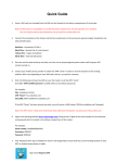
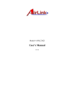
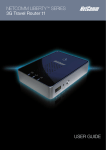
Model # ARW027
User’s Manual
Regulatory Notes and Statements
Health and Authorization for Use
Radio frequency electromagnetic energy is emitted from the Wireless LAN
device. The energy levels of these emissions are much less than the
electromagnetic energy emissions from wireless devices such as cell phones.
Wireless LAN devices are safe for use and meet the frequency safety
standards and recommendations. The use of Wireless LAN devices may be
restricted in some situations or environments such as:
•
•
•
On board of airplanes, or
In an explosive environment, or
In case the interference risk to other devices or services is perceived
or identified as harmful
If the policy regarding the use of Wireless LAN devices in specific
organizations or environments (e.g. airports, hospitals, chemical/oil/gas
industrial plants, private buildings, etc.) is not clear, please ask for
authorization to use these devices prior to operating the equipment.
Regulatory Information/Disclaimers
Installation and use of this Wireless LAN device must be in strict accordance
with the instructions included in the user documentation provided with the
product. Any changes or modifications made to this device that are not
expressly approved by the manufacturer may void the user’s authority to
operate the equipment. The manufacturer is not responsible for any radio or
television interference caused by unauthorized modification of this device and
of any substitution or attachment. The manufacturer and its authorized
resellers or distributors will assume no liability for any damage or violation of
government regulations arising from failure to comply with these guidelines.
ii
USA-FCC (Federal Communications Commission) Statement
This device complies with Part 15 of FCC Rules.
Operation is subject to the following two conditions:
1. This device may not cause interference, and
2. This device must accept any interference, including interference that may
cause undesired operation of this device.
FCC Radio Frequency Exposure Statement
This Wireless LAN radio device has been evaluated under FCC Bulletin OET
65 and found compliant to the requirements as set forth in CFR 47 Sections
2.1091, 2.1093, and 15.247 (b) (4) addressing RF Exposure from radio
frequency devices. The radiated output power of this Wireless LAN device is
far below the FCC radio frequency exposure limits. Nevertheless, this device
shall be used in such a manner that the potential for human contact during
normal operation is minimized.
When nearby persons has to be kept to ensure RF exposure compliance, in
order to comply with RF exposure limits established in the ANSI C95.1
standards, the distance between the antennas and the user should not be less
than 20 cm.
FCC Interference Statement
This equipment has been tested and found to comply with the limits for a
Class B digital device, pursuant to Part 15 of the FCC Rules. These limits are
designed to provide reasonable protection against harmful interference in a
residential installation.
This equipment generates, uses, and can radiate radio frequency energy. If not
installed and used in accordance with the instructions, it may cause harmful
interference to radio communications.
However, there is no guarantee that interference will not occur in a particular
installation. If this equipment does cause harmful interference to radio or
iii
television reception, which can be determined by turning the equipment off
and on, the user is encouraged to try and correct the interference by one or
more of the following measures:
1. Reorient or relocate the receiving antenna.
2. Increase the distance between the equipment and the receiver.
3. Connect the equipment to an outlet on a circuit different from that to which
the receiver is connected.
4. Consult the dealer or an experienced radio/TV technician for help.
Export restrictions
This product or software contains encryption code that may not be exported or
transferred from the US or Canada without an approved US Department of
Commerce export license.
Safety Information
Your device contains a low power transmitter. When the device is transmitted,
it sends out radio frequency (RF) signal.
CAUTION: To maintain compliance with FCC’s RF exposure guidelines, this
equipment should be installed and operated with a minimum distance of 20
cm between the radiator and your body. Unauthorized antenna, modification,
or attachments could damage the transmitter and may violate FCC regulations.
CE Mark Warning
This is a Class B product. In a domestic environment, this product may cause
radio interference which the user may be required to take adequate measures.
iv
Protection requirements for health and safety – Article 3.1a
Testing for electric safety according to EN 60950 has been conducted.
These are considered relevant and sufficient.
Protection requirements for electromagnetic compatibility –
Article 3.1b
Testing for electromagnetic compatibility according to EN 301 489-1,
EN 301 489-17 and EN 55024 has been conducted. These are
considered relevant and sufficient.
Effective use of the radio spectrum – Article 3.2
Testing for radio test suites according to EN 300 328-2 has been
conducted. These are considered relevant and sufficient.
v
TABLE OF CONTENTS
About This Guide .............................................................................2
Purpose.........................................................................................2
Overview of this User’s Manual....................................................2
Introduction ......................................................................................3
Applications .................................................................................4
Features ........................................................................................4
Unpacking and Setup........................................................................5
Unpacking ....................................................................................5
Setup ............................................................................................5
Hardware Installation........................................................................6
Front Panel ...................................................................................6
Rear Panel ....................................................................................7
Hardware connections...................................................................8
Connect the Router using LAN......................................................8
Connect the Router using Wireless LAN........................................9
Powering On .................................................................................9
Check the Installation ....................................................................9
PC Network TCP/IP Setting............................................................10
Windows 95/98/ME ....................................................................10
Windows 2000............................................................................12
Windows NT4.0..........................................................................13
Windows XP...............................................................................14
Wireless Broadband Router Configuration ......................................15
Login to the Wireless Broadband Router through WLAN ............15
Login to the Wireless Broadband Router through LAN................15
Using the Web Browser ..............................................................15
Quick Setup................................................................................16
Advanced Setup..........................................................................22
Technical Specifications .................................................................38
Appendix A....................................................................................40
Technical Support .......................................................................40
1
ABOUT THIS GUIDE
Congratulations on your purchase of this IEEE 802.11b Wireless
Broadband Router. This integrated access device combines Internet
gateway functions with wireless LAN and Fast Ethernet switch. It
provides a complete solution for Internet surfing and office resource
sharing, and it is easy to configure and operate for everyone.
Purpose
This manual discusses how to install the IEEE 802.11b Wireless
Broadband Router.
Overview of this User’s Manual
Introduction: Describes the Wireless Broadband Router and its features.
Unpacking and Setup: Helps you get started with the basic installation
of the Wireless Router.
Identifying External Components: Describes the front panel, rear panel
and LED indicators of the Wireless Router.
Connecting the Router: Describes how you can connect the Wireless
Router to your xDSL/Cable Modem.
Technical Specifications: Lists the technical (general, physical and
environmental) specifications of the Wireless Broadband Router.
2
INTRODUCTION
With the explosive growth of the Internet, accessing information and
services at any time, day or night, has become a standard requirement for
most people. The era of the standalone PC is waning. Networking
technology is moving out of the exclusive domain of corporations and
into homes with at least two computers.
This integrated access device combines Internet gateway functions with
wireless LAN and Fast Ethernet switch. Designed for the business and
home, it saves you the cost of installing a separate modem and ISP line
for each computer, while providing ready connection for the users, with or
without network cables.
Broadband network access is also gaining ground. However, allowing
more than two computers to access the Internet at the same time means
higher costs. Thus, there is a need to share one legal IP address over a
single Internet connection to link each computer with the Internet.
The scarcity of IP addresses and using a shared Internet connection
through an Internet sharing device can solve high network access costs.
All linked computers can make full use of broadband capabilities over
such a device.
This device not only comes equipped with a wide range of features, but
also comes installed and configured right out of the box. This device
supports a simple local area network and Internet access sharing, offering
great cost savings.
The local area network connects home computers while also allowing any
of the computers to access the Internet, share resources, or play online
games—the basis of the family computing lifestyle.
3
Applications
Broadband Internet access:
Several computers can share one high-speed broadband connection
through wireless or wired connections (WLAN, LAN and WAN-Internet).
Resource sharing:
Share resources such as printers, scanners and other peripherals.
File sharing:
Exchange data, messages, and distribute files.
Online gaming:
Online gaming and e-commerce services can be easily setup through the
local area network.
Firewall:
A built-in firewall function provides security and anti-hacking system.
Features
Ø
Ø
Ø
Ø
Ø
Ø
Ø
Ø
Ø
Ø
Ø
Ø
High speed data transfer rate
Supports NAT for sharing one IP address to all LAN users
Supports PPPoE and PPTP protocol for Dial-Up ADSL
Supports 64/128 bit WEP Encryption
Supports DHCP Server/Client
Supports UPnP (Universal Plug and Play)
Supports virtual server mapping
Supports packet filtering
Simple Firewall protection
Upgradeable firmware for future function
Simple setting using Quick Setup
Easy configuration via WEB Browser
4
UNPACKING AND SETUP
This chapter provides unpacking and setup information for the Wireless
Broadband Router.
Unpacking
Open the box and carefully unpack it. The box should contain the
following items:
u
u
u
u
One Wireless Broadband Router
One External Power Adapter
One Quick Installation Guide
One User’s Manual
If any item is found missing or damaged, please contact your local reseller
for replacement.
Setup
The setup of the Wireless Broadband Router can be performed properly
using the following methods:
u
The power outlet should be within 1.82 meters (6 feet) of the
Broadband Router.
u
Visually inspect the DC power jack and make sure that it is fully
secured to the power adapter.
u
Make sure there is adequate space around the Broadband Router.
Do not place heavy objects on the Broadband Router.
u
Fix the direction of the antennas. Try to place the Wireless
Router in a position that can best cover your wireless network.
Normally, the higher you place the antenna, the better the
performance will be. The antenna’s position enhances the
receiving sensitivity.
5
HARDWARE INSTALLATION
Front Panel
The figure below shows the front panel of the Wireless Broadband Router.
Wireless Broadband Router Front Panel
POWER
This indicator lights green when the hub receives power, otherwise it is
off.
SYSTEM
This indicator blinks green when the router is working properly, otherwise
it is off.
Link/ACT (WAN / LAN)
These indicators light green when the LAN/WAN ports are connected to
an xDSL/Cable modem successfully.
These indicators blink green while the LAN/WAN ports are transmitting
or receiving data through the xDSL/Cable modem.
Speed (WAN / LAN)
These indicators lights green when the ports are connected to
100Mbps Fast Ethernet Network, otherwise they remain off when the
ports are connected to 10Mbps Ethernet Network.
WLAN (ACT)
This indicator lights green when there are wireless devices connecting and
transmitting data through the Wireless Router.
6
Rear Panel
The figure below shows the rear panel of the Wireless Broadband Router.
Wireless Broadband Router Rear Panel
Antennas
There are two 2dBi Gain Antennas in the rear panel for wireless
connection.
DC IN
Plug the power adapter to this power jack.
WAN Port
Connect the xDSL/Cable modem to the WAN Port.
LAN (1-4)
Four RJ-45 10/100Mbps Auto-MDIX ports are available for either
10Mbps or 100Mbps Ethernet connections.
RESET
Use a pin-shaped item to push the reset button. It will reset the device to
factory default settings. This is useful when the administrator forgot the
password to login, but the settings will be back to default.
7
Hardware connections
Note: Prior to connecting the hardware, make sure to power off your
computer, DSL/Cable modem, and the Wireless Broadband Router.
Connect the Router using LAN
PC
PC
xDSL Modem
PC
WA
Np
ort
PC
LAN
por
t
WirelessBroadband Router
1.
2.
Connect one end of the network cable to the WAN port of the
Wireless Router and connect the other end of the cable to a DSL or
Cable modem.
With another network cable, connect one end of the cable to the
computer’s Ethernet card and connect the other end of the cable to
one of the LAN ports of the Wireless Router.
8
Connect the Router using Wireless LAN
Notebook
xDSL Modem
PC
WA
Np
ort
Notebook
WirelessBroadband Router
1.
Wireless LAN Networking
Connect one end of the network cable to the WAN port of the
Wireless Router and connect the other end of the cable to a DSL or
Cable modem.
Powering On
1.
Power on the DSL/Cable modem first. Then power on the wireless
broadband router by connecting the power adapter to the power jack of
the router. Finally, power on your computer.
Check the Installation
The control LEDs of the Wireless Router are clearly visible and the status
of the network link can be seen instantly:
1. With the power source on, once the device is connected to a
broadband modem, the Power, LAN, WLAN and WAN port link
LEDs of the Internet Broadband Router will light up indicating a
normal status.
2. When the WAN is connected to the ADSL/Cable modem, the WAN
port’s Link/ACT LED will light up.
3. When the LAN is connected to the computer system, the LAN port’s
Link/ACT LED will light up.
9
PC NETWORK TCP/IP SETTING
The network TCP/IP settings differ based on the computer’s operating
system (Win95/98/ME/NT/2000/XP) and are as follows.
Windows 95/98/ME
1.
2.
3.
Right-click the Network neighborhood icon on the desktop.
Select TCP/IP and click Properties.
Select Obtain an IP address automatically in the IP address tab.
10
4.
Select Disable DNS in the DNS tab.
5.
Select None for the Gateway tab and click OK.
11
Windows 2000
1.
2.
3.
4.
Right-click My Network Places on the desktop.
Right-click Local Area Connection and select Properties.
Select Internet Protocol (TCP/IP) and click Properties.
Select Obtain an IP address automatically and Obtain DNS
server address automatically, and click OK.
12
Windows NT4.0
1.
2.
3.
4.
5.
Go to Start and then Control Panel.
Select Network to enter the TCP/IP setting window.
Select TCP/IP Protocol and click Properties.
Select Obtain an IP address automatically in the IP Address tab.
Select Disable DNS in the DNS tab and click OK.
13
Windows XP
1.
2.
3.
4.
Right-click My Network Places on the desktop.
Right-click Local Area Connection and select Properties.
Select Internet Protocol (TCP/IP) and click Properties.
Select Obtain an IP address automatically and Obtain DNS
server address automatically, and click OK.
14
WIRELESS BROADBAND ROUTER CONFIGURATION
First make sure that the network connections are functioning normally.
This Wireless Broadband Router can be configured using Internet
Explorer 4.0 or newer web browser versions.
Login to the Wireless Broadband Router through WLAN
Before configuring the Wireless Broadband Router through WLAN, make
sure that the Operation Mode, SSID, Authentication, and the WEP
settings of your wireless adapter are set properly:
Operation Mode: Infrastructure
SSID: default
Authentication: Open
WEP Encryption: disabled
Login to the Wireless Broadband Router through LAN
Before you configure this device, note that when the Wireless Broadband
Router is configured through an Ethernet connection, make sure the host
PC must be set on the IP subnet that can be accessed by the xDSL/Cable
modem. For example, when the default network address of the
xDSL/Cable modem Ethernet interface is 192.168.1.x, then the host PC
should be set at 192.168.1.xxx (where xxx is a number between 2 and
254), and the default subnet mask is 255.255.255.0.
Using the Web Browser
1.
2.
Open Internet Explorer 4.0 or above Internet browser.
Enter IP address http://192.168.1.1 (the factory-default IP address
setting) in the URL web address location.
15
3.
When the following dialog box appears, leave the Password field
blank (first login) and click Login to enter the main configuration
window.
Note: To set a password, refer to the Administrator Settings in
Advanced Setup.
4.
It is recommended that beginners use the Quick Setup option. It
will lead you step by step to configure the Wireless Router.
Quick Setup
In the main web page, select Quick Setup to specify the Time Zone,
Wireless Settings, and WAN connection type.
16
1-1 Time Zone
Select your time zone. You can also configure the optional Daylight
Saving time. Click Next to go the next page.
1-2 Wireless Settings
Set the desired SSID, Country (Domain Regulatory), Channel, and
WEP Settings of the Wireless Router and click Next.
Note: your wireless adapter must be set to the same settings in order
for there to be proper wireless connection.
1-3 WAN Connection Type
Select the applicable WAN connection type that your Internet Service
Provider (ISP) is using. If you are not sure which WAN connection type
your ISP is using, please contact your ISP for assistance.
17
1-3-1 Dynamic IP (Cable modem) [DHCP]
The Host Name is optional but may be required by some ISPs. The default
MAC address is set to the WAN's physical interface on the Broadband
Router. If the ISP requires a host name, click Clone MAC Address to
copy the MAC address of the PC’s network card. It will replace the WAN
MAC address with the network card’s MAC address. Click Next to go to
the next page.
1-3-2 Static IP (Fixed-IP xDSL)
If your ISP assigns a fixed IP address, choose this option and enter the
assigned IP address, Subnet Mask, and ISP Gateway Address provided by
your ISP. Click Next to go to the next page.
18
1-3-3 PPPoE (Dial-Up xDSL)
If you have to supply a user name and password to connect to the Internet,
choose this option. Enter your user name and password in the appropriate
fields. If your ISP provided a Service Name, enter it in the Service Name
field, otherwise, leave it blank.
The fields in the Service Name, IP Address, and DNS Address must be
filled up when the ISP provides these information to you. If the ISP uses
Dynamic IP Address, then you can skip these fields.
The MTU specifies the largest packet size permitted for network
transmission. Enter the value desired. For most DSL users, it is
recommended to use the default value of 1492.
The Maximum Idle Time determines the maximum idle time allowed
before a connection is dropped (default time=0, always connected).
Connect-on-demand allows you to make a connection automatically when
there is a need for connection. Click Next to go to the next page.
19
1-3-4 PPTP
If you are using PPTP to connect to the Internet, select this option. Enter
the PPTP Account Name, PPTP Password, Host Name, Service IP
Address, Your IP Address, and Your Subnet Mask. If your ISP provided
you with a Connection ID, enter it in the Connection ID field, otherwise,
leave it as zero.
The MTU specifies the largest packet size permitted for network
transmission. Enter the value desired. For most PPTP users, it is
recommended to use the default value of 1460.
The Maximum Idle Time determines the maximum idle time allowed
before a connection is dropped (default time=0, always connected).
Connect-on-demand allows you to make a connection automatically when
there is a need for connection. Click Next to go to the next page.
1-4 DNS
If your ISP provided at least one DNS Server IP Address, type that IP
Address in the Primary DNS address field. You can enter another DNS
Server IP Address in the Secondary DNS address field. The Router will
use these addresses for quicker access to the DNS Servers. If your ISP did
not provide you with any DNS server address, just leave the fields blank.
Click Finish to complete the setup.
20
21
Advanced Setup
The Broadband Router supports advanced functions like System setting,
WAN setting, LAN setting, WLAN setting, NAT Setting, and Firewall
setting.
2-1 System
This page includes all the basic configuration tools for the Broadband
Router. Click on the selections at the left side of the menu screen.
2-1-1 System Time
Connecting to a Simple Network Time Protocol (SNTP) server allows the
Broadband Router to synchronize its system clock with the global Internet
through the SNTP server. The system clock in the Broadband Router is
used to record the system log and control client filtering.
22
2-1-2 Administrator Settings
•
Password Settings
Set a password to restrict management access to the Broadband Router.
• Remote Management from Internet
To manage the Broadband Router from a remote location (outside of the
local network through WAN port), check the Enable box and specify the
IP address of the remote PC. Leaving the IP address 0.0.0.0 will allow all
public IP addresses to access the router.
2-1-3 Firmware Upgrade
After you have downloaded a new firmware to your computer,
enter/browse to the path of the upgrade file and click APPLY. You will
be prompted to confirm the upgrade.
While updating the firmware, please wait after clicking the APPLY
button, and follow the instructions on the screen. The System Light on
23
the front panel will start to blink when the firmware upgraded
successfully.
2-1-4 Configuration Tools
Use the "Backup Settings" tool to save the Broadband Router's current
configuration to a file named "config.bin" on your PC. You can then use
the "Restore Settings" tool to restore the saved configuration of the
Broadband Router that you set before. Alternately, you can use the
"Restore Factory Default Configuration" tool to force the Broadband
Router to perform reset and restore the original factory settings.
•
•
•
Restore Factory Default
To restore the factory default settings of the Broadband Router,
click on the “Restore” button.
Backup Settings
Press the “Backup Settings” button to save the current setting in a
file named “config.bin” or another given filename.
Restore Settings
To restore the backup file to the Broadband Router, enter the path
and filename of the restore settings.
24
2-1-5 Status
Use the Status screen to see the connection status for the Wireless
Broadband Router’s WAN, LAN, WLAN interfaces, firmware, hardware
version numbers, and the number of connected clients on the network.
25
2-1-6 System Log
View any attempts that have been made to gain access to the network.
2-1-7 Reset
In the event that the Broadband Router stops responding correctly or in
some way stops functioning, perform the reset function. The settings will
not be changed. To perform the reset, click on the "Reset" button. The
reset will be complete when the system light starts to blink.
2-2 WAN
The Broadband Router can be connected to the ISP in any of the
following ways: Dynamic IP Address, Static IP Address, PPPoE, and
PPTP.
2-2-1 Dynamic IP
The Host Name is optional, but may be required by some Service
Providers. The default MAC address is set to the WAN's physical
interface on the Broadband Router. If the Service Provider requires the
host name, use the "Clone MAC Address" button to copy the MAC
26
address of the PC’s network card. It will replace the WAN MAC address
with the network card’s MAC address.
The road runner management is optional. If the ISP needs to run the road
runner management (sometimes called Big Pond), enable it.
2-2-2 Static IP
If the Service Provider has assigned a fixed IP address, enter the assigned
IP address, Subnet Mask and ISP Gateway Address provided by your ISP.
Check Yes if you are using two or more IP addresses.
2-2-3 Dial-up xDSL (PPPoE)
If connected to the Internet using a Dial-up xDSL (PPPoE) Modem, the
ISP will provide a Password and User Name. Choose this option and enter
the required information. If the ISP provided a Service Name, enter it in
the Service Name field, otherwise, leave it blank.
The fields in Service Name, IP Address, and DNS Address must be filled
up when the ISP provides these information to you. If the ISP uses
Dynamic IP Address, then you can skip these fields.
The MTU specifies the largest packet size permitted for network
transmission. Enter the value desired. For most DSL users, it is
recommended to use the default value of 1492.
27
The Maximum Idle Time determines the maximum idle time allowed
before a connection is dropped (default time=0, always connected).
Connect-on-demand allows you to make a connection automatically when
there is a need for connection.
2-2-4 PPTP
If you are using PPTP to connect to the Internet, select this option. Enter
the PPTP Account Name, PPTP Password, Host Name, Service IP
Address, Your IP Address, and Your Subnet Mask. If your ISP provided
you with a Connection ID, enter it in the Connection ID field, otherwise,
leave it as zero.
The MTU specifies the largest packet size permitted for network
transmission. Enter the value desired. For most PPTP users, it is
recommended to use the default value of 1460.
The Maximum Idle Time determines the maximum idle time allowed
before a connection is dropped (default time=0, always connected).
Connect-on-demand allows you to make a connection automatically when
there is a need for connection.
28
2-2-5 DNS
If your ISP provided at least one DNS Server IP Address, type that IP
Address in the Primary DNS address field. You can enter another DNS
Server IP Address in the Secondary DNS address field. The Router will
use these addresses for quicker access to the DNS Servers. If your ISP did
not provide you with any DNS server address, just leave the fields blank.
2-3 LAN
Sets the Router’s IP Address and DHCP Service
2-3-1 LAN Settings
The router’s default IP Address is 192.168.1.1 with a default Subnet Mask
of 255.255.255.0. You can change these values as needed.
29
To enable the DHCP server for dynamic IP address allocation to the
clients, select the “Enable” check box. The clients can get their IP address
from a range of IP Pool Addresses.
The Lease Time is the amount of time a client will be allowed to connect
to the Router using the assigned IP address. You can enter your local
domain name in the Local Domain Name field.
2-3-2 DHCP Client List
The DHCP client list allows you to see which clients are connected to the
router via their IP address, host name, and MAC address.
2-4 WLAN
Sets the WLAN’s SSID, Regulatory Domain, Channel, and WEP
Encryption
30
2-4-1 WLAN Setting
•
•
SSID: The SSID differentiates one WLAN group from another;
so all access points and all devices attempting to connect to a
specific WLAN group must use the same SSID. A device will not
be permitted to join the WLAN group unless it can provide the
unique SSID.
Country: This is the channel selection of each country regulatory
domain. Select the country where you are using the Wireless
Broadband Router. Users are responsible for ensuring that the
channel set configuration is in compliance with the regulatory
standards of these countries. The default setting of this Wireless
Broadband Router follows the FCC rules using Channel 1~11.
Warning: Be noted that selecting the incorrect region may result
in a violation of applicable law; you will need to select the correct
domain.
•
DS Channel: Set the radio channel number used for WLAN
networking. Default is Channel 6.
31
WEP Key Setting
When enabling the WEP Key Setting, the security of the Wireless
Broadband Router will be activated. It will prevent unauthorized
access to your wireless network.
• WEP Key Type: selection of WEP key format using HEX type
(hexadecimal 0~F) or ASCII type (alphanumeric 0~9, A~Z and
a~z).
• 64 bit Encryption: If you select 64 bit encryption using HEX
mode, you must type 10 values in the following range (0~F,
hexadecimal) in key 1 to key 4. If you select 64 bit in ASCII
format, you must type 5 values in the following range (0~9, A~Z
and a~z Alphanumeric).
• 128 bit Encryption: If you select 128 bit encryption using HEX
mode, you must type 26 values in the following range (0~F,
hexadecimal) in key 1 to key 4. If you select 128 bit in ASCII
format, you must type 13 values in the following range (0~9, A~Z
and a~z Alphanumeric).
• Default Key: select the default key that you want to use in this
Wireless Broadband Router.
• Authentication Type:
Open System: with the same WEP key between the stations, the
stations don’t need to be authenticated. This algorithm is mostly used.
Shared Key: with the same WEP key between the stations the
stations need to be authenticated first.
Auto: by selecting this auto mode, the system will automatically
select which authentication type is suitable for the WLAN networking.
32
2-4-2 AP Client List
The AP client list allows you to see which clients are connected to the
Wireless Broadband Router via their MAC address.
Click “Refresh” to refresh the list.
2-5 NAT
Network Address Translation (NAT) allows multiple users at the local site
to access the Internet through a single public IP address. NAT can also
prevent hacker attacks by mapping local addresses to public addresses for
key services such as Web or FTP.
33
2-5-1 Special Application
Some applications require multiple connections, such as Internet gaming,
video conferencing, Internet telephony and others. These applications
cannot work when Network Address Translation (NAT) is enabled. When
users send this type of request to your network via the Internet, the Router
will forward those requests to the appropriate PC. If you need to run
applications that require multiple connections, specify the port normally
associated with an application in the "Trigger Port" field, select the
protocol type as TCP or UDP, then enter the public ports associated with
the trigger port to open them for inbound traffic.
• TCP (Transmission Control Protocol) - A communications method
(protocol) used along with the Internet Protocol (Internet Protocol) to
send data in the form of message units between computers over the
Internet. While IP takes care of handling the actual delivery of the
data, TCP takes care of keeping track of the individual units of data
(called packets) that a message is divided into for efficient routing
through the Internet.
• UDP (User Datagram Protocol) - A communications method
(protocol) that offers a limited amount of service when messages are
exchanged between computers in a network that uses the Internet
Protocol (IP). UDP is an alternative to TCP and, together with IP, is
sometimes referred to as UDP/IP. Like the Transmission Control
Protocol, UDP uses the Internet Protocol to actually send a data unit
(called a datagram) from one computer to another. Unlike TCP,
however, UDP does not provide the service of dividing a message
into packets and reassembling it at the other end. Specifically, UDP
doesn't provide sequencing of the packets that the data arrives in.
This means that the application program that uses UDP must be able
to make sure that the entire message has arrived and is in the right
order. Network applications that want to save processing time
because they have very small data units to exchange (and therefore
very little message reassembling to do) may prefer UDP to TCP.
34
Example:
ID
Trigger Port
Trigger
Type
Public Port
Public
Type
Comment
1
28800
UDP
2300-2400, 47624
UDP
MSN Game
Zone
2
28800
UDP
2300-2400, 47624
TCP
MSN Game
Zone
3
6112
UDP
6112
UDP
Battle.net
2-5-2 Virtual Server
Configure the Broadband Router as a virtual server to allow the Router to
watch outgoing data for specific port numbers. The IP address of the
computer that sends the matching data is remembered by the Router, so
that when the requested data returns through the Router, the data is pulled
back to the proper computer by way of IP address and port mapping rules.
Depending on the requested service (TCP/UDP port number), the
Broadband Router redirects the external service request to the appropriate
server.
Example:
35
ID
Server IP
Mapping Port
Type
Comment
1
192.168.2.20
80
TCP
Web Server
2
192.168.2.12
20
TCP
FTP Server
3
192.168.2.12
21
TCP
FTP Server
4
192.168.2.28
23
TCP
Telnet Server
2-6 Firewall
The Broadband Router provides extensive firewall protection by
restricting connection parameters to limit the risk of hacker attacks, and
defending against a wide array of common hacker attacks.
The Broadband Router provides packet filtering rules by restricting
service ports, IP address, or MAC address. However, for applications that
require unrestricted access to the Internet, configure a specific
client/server as a demilitarized zone (DMZ).
2-6-1 Block WAN Ping
When the "Discard PING from WAN side" is activated, the Broadband
Router will not to respond to ping commands originating from the WAN.
Pinging public WAN IP addresses is a common method used by hackers
to test whether the WAN IP address is valid and supports a network.
36
2-6-2 Client Filtering
You can filter Internet access for local clients based on IP addresses,
application types, (i.e., HTTP port), and the time of day.
For example, the following picture shows that clients in the address range
192.168.1.50-99 are permanently restricted from using FTP (Port 21),
while clients in the address range 192.168.1.110-119 are blocked from
browsing the Internet (port 80) from Monday to Friday and from 0:00AM
to 11:00 PM.
Example:
2-6-3 MAC Control
You can block certain client PCs from accessing the Internet based on
their MAC address.
2-6-4 DMZ (Demilitarized Zone)
If a local client PC cannot run an Internet application properly from
behind the NAT firewall, open the client up to unrestricted two-way
Internet access by defining a virtual DMZ Host.
37
TECHNICAL SPECIFICATIONS
General
Standards
IEEE 802.3u 100BASE-TX Fast Ethernet
IEEE 802.11b
Protocol
CSMA/CD
Radio
Technology
IEEE 802.11b Direct Sequence Spread Spectrum (DSSS)
Data Transfer
Rate
WLAN: 1, 2, 5.5, 11Mbps (auto sense)
Ethernet: 10Mbps (half duplex), 20Mbps (full-duplex)
Fast Ethernet: 100Mbps (half duplex), 200Mbps (full- duplex)
Topology
Star
Receiver
Sensitivity
11Mbps: Typical –83dBm @ 8% PER (Packet Error Rate)
2Mbps: Typical –84dBm @ 8% PER (Packet Error Rate)
Network
Cables
10BASE-T: 2-pair UTP Cat. 3,4,5 (100 m), EIA/TIA- 568 100ohm STP (100 m)
100BASE-TX: 2-pair UTP Cat. 5 (100 m), EIA/TIA-568 100ohm STP (100 m)
Frequency
Range
2400 ~ 2497 MHz ISM band (channels 1 ~ 14)
Modulation
Schemes
DBPSK/DQPSK/CCK
Security
64/128-bit WEP Encryption
Channels
1 ~ 11 channels (FCC); 1 ~ 13 channels (ETSI);
1 ~ 14 channels (Japan)
Number of
Ports
LAN: 4 x 10/100Mbps Auto-MDIX Fast Ethernet port
WAN: 1 x 10/100Mbps Auto-MDIX Fast Ethernet port
38
Physical and Environmental
DC inputs
DC 7.5V 1A
Power
Consumption
3W (Max)
Temperature
Operating: 0° ~ 40° C, Storage: -10° ~ 70° C
Humidity
Operating: 10% ~ 90%, Storage: 5% ~ 90%
Dimensions
171 x 100 x 34 mm (W x H x D) without Antenna
EMI:
FCC Class B, CE Mark B
39
APPENDIX A
Technical Support
E-mail: [email protected]
Toll Free: 1-888-746-3238
Web Site: www.airlinkplus.com
40