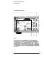
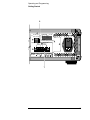
1
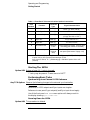
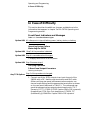
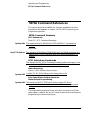
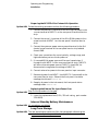
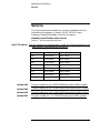
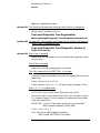
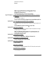
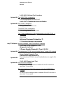
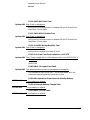
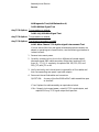
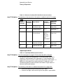
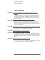
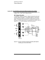
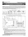
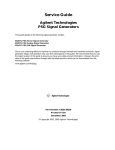
$JLOHQW $3ULPDU\)UHTXHQF\6WDQGDUG 7HOHFRPPXQLFDWLRQV2SWLRQV 7HOHFRPPXQLFDWLRQV 2SWLRQV6XSSOHPHQWDO 0DQXDO Telecommunications Options Supplemental Manual This manual describes the Telecommunications options for the Agilent 5071A Primary Frequency Standard. The information in this manual applies toinstruments with one or more telecommunications options having the number prefix listed below, unless accomplanied by a "Manual Updating Changes" package indicating otherwise. SERIAL NUMBER PREFIX: 3249A and above Options: 048, 104, 105, 220, 221, 222, 270, 271, and 272 Agilent 5071A Primary Frequency Standard Copyright Agilent Technologies, Inc. 1994, 2000 All Rights Reserved. Reproduction, adaptation, or translations without prior written permission is prohibited, except as allowed under the copyright laws. Printed: December 2000 Printed in USA Manual part number 05071-90042 Certification and Warranty Certification Agilent Technologies certifies that this product met its published specification at the time of shipment from the factory. Agilent further certifies that its calibration measurements are traceable to the United States National Institute of Standards and Technology (formerly National Bureau of Standards), to the extent allowed by the Institute’s calibration facility, and to the calibration facilities of other International Standards Organization members. Safety Considerations General Safety Considerations (contd) This product and related documentation must be reviewed for familiarization with this safety markings and instructions before operation. Indicates earth (ground) terminal. This product is a safety Class I instrument (provided with a protective earth terminal). or Before Applying Power Verify that the product is set to match the available line voltage and the correct fuse is installed. Refer to instructions in Chapter 1 of the Manual. Indicates terminal is connected to chassis when such connection is not apparent. Warranty Agilent warrants Agilent hardware, accessories and supplies against defects in materials and workmanship for a period of one year from date of shipment. If Agilent receives notice of such defects during the warranty period, Agilent will, at its option, either repair or replace products which prove to be defective. Replacement products may be either new or like-new. Agilent warrants that Agilent software will not fail to execute its programming instructions, for the period specified above, due to defects in material and workmanship when properly installed and used. If Agilent receives notice of such defects during the warranty period, Agilent will replace software media which does not execute its programming instructions due to such defects. Before Cleaning Disconnect the product from operating power before cleaning. Safety Earth Ground An uninterruptible safety earth ground must be provided from the mains power source to the product input wiring terminals or supplied power cable. Warning Symbols That May Be Used In This Book Indicates Alternating current. Indicates Direct current. WARNING BODILY INJURY OR DEATH MAY RESULT FROM FAILURE TO HEED A WARNING. DO NOT PROCEED BEYOND A WARNING SIGN UNTIL THE INDICATED CONDITIONS ARE FULLY UNDERSTOOD AND MET. CAUTION Instruction manual symbol; the product will be marked with this symbol when it is necessary for the user to refer to the instruction manual. Damage to equipment, or incorrect measurement data, may result from failure to heed a caution. Do not proceed beyond a CAUTION sign until the indicated conditions are fully understood and met. For additional safety and acoustic noise information, see back matter. For detailed warranty information, see back matter. Indicates hazardous voltages. Agilent Technologies, Inc. Santa Clara Site 5301 Stevens Creek Boulevard Santa Clara, California 95052-8059 8.CD.NL.A.03.11.97.R1.J.CW2F MANUAL UPDATING CHANGES CHANGE DATE: December 12, 2001 MANUAL UPDATING COVERAGE MANUAL IDENTIFICATION This supplement adapts your manual to Serial Numbers prefixed through: Instrument: Agilent 5071A Primary Frequency Standard Telecommunications Options Supplemental Manual US3930 Manual Print Date: December 2000 Manual Part Number: 05071-90042 ABOUT THIS SUPPLEMENT The information in this supplement is provided to correct manual errors and to adapt the manual to instruments containing changes after the manual print date. Change and correction information in this supplement is itemized by page numbers corresponding to the original manual pages. The pages in this supplement are organized in numerical order by manual page number. HOW TO USE THIS SUPPLEMENT Insert this title page in front of the title page in your manual. Perform all changes specified for “All Serials”, and all changes through the Series Prefix of your instrument or board. Insert any complete replacement pages provided into your manual in the proper location. The following pages are included in this update: If your manual has been updated according to the last edition of this supplement, you need only perform those changes pertaining to the new series prefix; see List of Effective Pages. New information affecting “All Serials” will be indicated by a “#” in front of the change. LIST OF EFFECTIVE PAGES SERIAL PREFIX, SERIAL # OR DATE CODE # PAGES All Serials ....................... 3-3. All Serials ....................... All pages. MANUAL CHANGES AGILENT 5071A TELECOMMUNICATIONS OPTIONS SUPPLEMENTAL MANUAL SERIAL PREFIX, SERIAL # OR DATE CODE # CHANGES Page 3-3, Accessories Furnished, dc input connector All Serials >Add the following Option 048: Delete reference to dc input connector part number 1251-0126 Title Page, Serial Number Prefix All Serials >Change from "3249A and above" to "US3930" Throughout The Entire Manual All Serials >Change all references of "HP" to "Agilent" >Change all references of "HP 5071A" to "5071A" (05071-90042, December 2000) Contents Preface How to Use This Manual v Instrument Identification v Instruments Covered by This Manual Manual Organization vi How to Order Manuals vi 1 vi Operating and Programming Introduction 1-2 Introducing the HP 5071A 1-2 HP 5071A Major Features 1-2 Operating The HP 5071A 1-2 Clock Functions 1-2 Getting Started 1-3 The HP 5071A at a Glance 1-3 Connectors 1-3 Rear Panel Connections 1-3 Starting The HP 5071A 1-6 Performing Basic Tasks 1-6 Synchronizing to an External 1 PPS Reference 1-6 Powering Down the HP 5071A 1-6 Using the HP 5071A 1-7 Monitoring Status 1-7 Disabling the Internal Standby Battery 1-7 In Case of Difficulty 1-8 Front-Panel Indicators and Messages 1-8 Operating System Failures 1-8 Restarting the HP 5071A 1-8 Verifying Operation 1-8 2. Rear-Panel Output Connectors 1-8 HP 5071A Command References 1-9 HP 5071A Command Summary 1-9 SCPI Commands 1-9 SCPI Subsystem Commands 1-9 Status Reporting 1-9 Rear-Panel Status Output Operation 1-9 Status Output Programming 1-9 iii Contents Installation 1-10 Preparation for Use 1-10 Power Requirements 1-10 Bench Operation 1-10 Operating the HP 5071A From External Dc Power 1-10 Preparing the HP 5071A For External Dc Operation 1-11 Replacing the External Dc Input Power Fuse 1-11 Internal Standby Battery Maintenance 1-11 Long-Term Storage 1-11 2 Service Performance Tests 2-2 Service 2-3 Top-Level Diagnostic Tree Organization 2-4 Warmup and Fatal Error Diagnostic Tree 2-5 Advisory Messages 2-6 Assembly/Module Diagnostic Trees 2-8 A9 Diagnostic Tree (A/M Subsection 4) 2-9 Theory of Operation 2-10 Introduction 2-10 Simplified Functional Description 2-10 Functional Block Descriptions 2-11 Instrument Control Block 2-12 Reference Oscillator/RF-Chain Block 2-12 Input/Output 2-13 Power Supply Block 2-14 A1 Motherboard Circuit Description 2-15 A11 Power Steering Logic Assembly 2-16 48V Subpanel Assembly 2-17 B1 Internal-Standby Battery 2-18 Replaceable Parts 2-19 Exchange Assemblies 2-19 Backdating iv 2-21 Contents 3 Specifications Supplemental Characteristics 3-2 Time Standard 3-2 Clock 1PPS Outputs 3-2 Clock Synchronization 3-2 Internal Standby Battery (Nominal Values) Environmental 2-9 Power Requirements 3-2 Weight 3-3 Accessories Furnished 3-3 dc input connector 3-3 Available Accessories and Options Options 3-4 3-2 3-4 v Contents vi Preface This manual provides operating, programming, and assembly-level service information for the HP 5071A Primary Frequency Standard Telecommunications options. How to Use This Manual Telecommunications option information is presented as changes, additions, and deletions to the material covered in the HP 5071A Operating and Programming and Assembly-Level Service manuals. The information appears in sequential order of occurrence corresponding to the subject headings that are affected by the options. Each occurrence of telecommunications option information uses the following presentation format: Subject heading(s): a. Left-justified option designation where: Option 048 = 48 Vdc power option, and Any TCO Option = Telecommunications output options 104, 105, 220, 221, 222, 270, 271, or 272. b. Text information explanation for either HP 5071A manual, and/or, c. Corrected text information for the cited subject heading(s) Except for the rear-panel illustration in chapter 1 of the HP 5071A Operating and Programming manual and Figure 2-1, all changes and corrections to manual illustrations appear as descriptive text items that convey new, changed, or deleted information about the artwork. The structure of topics covered corresponds to the outlines of the HP 5071A Operating and Programming and Assembly-Level Service manual except for specifications which occupies its own chapter. (See manual organization below.) Instrument Identification Instrument identification is made from the serial number located on the rear panel of the HP 5071A. Agilent uses a two-part serial number with the first part (prefix) identifying a series of instruments and the second part (suffix) identifying a particular instrument within a series. An Agilent assigned alpha character between the prefix and suffix identifies the country in which the instrument was manufactured. vii Preface Instruments Covered by This manual This manual applies to any HP 5071A Primary Frequency Standard that is equipped with one or more of the telecommunications options shown on the title page and has the same serial number prefix(es) also shown on the title page. If the serial number prefix of your standard differs from that listed on the title page of this manual, then there may be differences between this manual and your instrument. Instruments having a higher serial prefix are covered when required by one or more manual-change sheets included with this manual. If a required change sheet is missing, contact your nearest Agilent Sales Office listed at the back of this manual. Manual Organization This telecommunication options supplemental manual consists of a table of contents, preface, and three chapters. The page running headers identify the chapters and sections of this manual. The chapter contents are summarized as follows: Chapter 1, Operating and Programming, is divided into seven sections: Introduction, Getting Started, Using the 5071A, In Case of Difficulty, HP 5071A Command References, and Installation. Chapter 2, Assembly-Level Service, is divided into five sections: Performance Tests, Service, Theory of Operation, Replaceable Parts, and Backdating. Chapter 3, Specifications, is divided into two sections: Supplemental Characteristics, and Available Accessories and Options. How to Order Manuals This manual’s part number is 05071-90031. Use it to order copies of this manual. The HP 5071A Operating and Programming manual part number is 05071-90029. The HP 5071A Assembly-Level Service manual part number is 05071-90003. viii 1 Operating and Programming Operating and Programming Introduction Introduction This section describes the additions, changes, and deletions to the information that appears in the introduction of the 5071A Operating and Programming manual. Introducing the 5071A 5071A Major Features Option 048: In the bulleted text delete: • 45 minute standby battery Operating The 5071A Clock Functions Any TCO Option: 1st paragraph, 2nd sentence is changed: The 1 pps output is moveable in time and can be automatically synchronized with other 1 PPS sources. Any TCO Option: 3rd paragraph is changed: 1 pps output: There is one 1 pps output on the 5071A front panel. Any TCO Option: 4th paragraph is changed: The 1 pps output is TTL compatible and requires 50Ω termination. You can automatically synchronize the 1 PPS signal to an external 1 PPS, or manually change its timing by up to ± 500 ms in 50 ns steps. Use the front-panel Sync Input for an external system reference input. Option 048: 2nd paragraph (page vii) is changed: Power input and management: The 5071A operates from either ac or dc power. Power-source priority is controlled by the 5071A. The priority order is: 1. External dc power: when below the specified minimum voltage (40 Vdc on both dc inputs), or when absent, the 5071A switches to, 2. Ac line power. (Item 3 is deleted.) 1-2 Operating and Programming Getting Started Getting Started This section describes the additions, changes, and deletions to the information that appears in chapter 1 of the 5071A Operating and Programming manual. CHAPTER GUIDE Where to Find Important Topics Option 048: In the bulleted list delete: • Powering Down the 5071A 1-8 The 5071A at a Glance Connectors Any TCO Option: The paragraph immediately following item 8. Sync Input is changed(The electrical characteristics of these connectors are the same as the rear-panel 1 pps Output and Sync Input. See “Rear-Panel Features” on page 4 and 5 for more information.) The rear-panel 1 pps outputs and sync input connectors are absent. The front-panel 1 pps output and sync input signal characteristics are however accurately described by items 5 and 6 of Table 1-1 “Connector Descriptions” in the Operating and Programming manual. Rear-Panel Connections Table 1-1 Connector Descriptions items in the Operating and Programming manual are changed: Any TCO Option: Option 048: Items 5 and 6 are absent from the rear-panel. Item 9 is absent. Item 10 Connector Type is a 5-screw terminal strip. Item 10 Signal Characteristics are 40-58 Vdc on the rear-panel terminal strip dc-power inputs 1 and/or 2 with GND as chassis ground. 1-3 Operating and Programming Getting Started 5071A Rear Panel Connections (See Table 1-1 in this chapter for connector descriptions) 1 OPTIONS SERIAL PLATE 8 kHz Sync In TTL 50W OUTPUTS +13 dBm 50 W Sine Wave 5071A 8 kHz Sync Out ! RS - 232C (DTE) WARNING: TTL 50W To avold electric shock, do not remove covers. No user-serviceable parts inside. Refer all servicing to qualified personnel. Programmable outputs 5MHz or 10MHz 1 MHz Framed Output CAUTION: 92 100 kHz ! G.703/6 G.704 50W METRIC & INCH HARDWARE CONSULT SERVICE MANUAL Port 2 Status Output 001 Hi Performance 12.75 x 32 Port 1 2 Sync Out 2.048 Mb/s Sync Out ISM 1-A FOR LABORATORY USE BY QUALIFIED PERSONNEL FOUR USAGE EN LABORATOIRE PAR PERSONNEL QUALIFIE 75W G.703/10 3 50W TTL 4 5 NOTE The illustration on these pages depicts an 5071A equipped with Telecomm Options 048 and 272. When the telecomm output option includes either 100 or 120 Ω balanced output lines, the Framed Output connector will be a two-center-conductor BNC in place of the one shown above. In addition, the Mb/s and impedance designations will correspond to the particular telecomm output option shipped with the 5071A. 1-4 Operating and Programming Getting Started 9 48 VDC Input Fuse: 2.5A 250V FUSE POWER/FUSE Line: 1 100VA MAX 00/120 V Fuse: Freq: 1.5 5 AT 0-400 Hz 5 220/240 V 0.8 AT 0-60 Hz CAUTION: For continued protection against fire, replace only with fuse of s ame type and ratings. 120 Vac ! Operating Voltage Range: 40 to 5 8 VDC Input 1 GND Input 2 48 VDC TELECOM OPTIONS: 48Volt 048 48 VDC 1.544 Mb/s 104 105 2.048 Mb/s 220 270 221 271 222 272 7 1-5 Operating and Programming Getting Started Table 1-1 Rear-Panel Telecommunications Options Connections Item Number Function Connector Type Signal Characteristics 1 8 kHz Sync In BNC (F) 8 kHz, TTL level, into 50 Ω 2 8 kHz Sync Out BNC (F) 8 kHz, TTL level, into 50 Ω 3* Framed Output BNC (F) 4.8 V p-p max into 75 Ω (6V p-p into 100, or 120 Ω) 4* Sync Out BNC (F) 3 V p-p max into 75 Ω 5 Sync Out BNC (F) TTL level, into 50 Ω 6 Dc Power Fuse Cartridge Fuse Fuses external dc power, 2.5 amp, 250volt rating (part number 2110-0952) 7 Dc Power Input 5-Screw Terminal Strip 40 - 58 Vdc, 100 W Max, as labeled on rear panel (See bottom of page 1-10) * Note: Item 3, Framed Output complies with ITU-T (formerly CCITT) G.703/6 (G.703/2 if option 104 or 105 is present) formatted per G.704. Item 4, per G.703/10, 75 Ω (Additionally @ 1.544 MHz if option 104 or 105 present). Starting The 5071A Option 048: Bottom of page 1-6. * note is changed: * 1 entry may be present: “Power source is BATT” Performing Basic Tasks Synchronizing to an External 1 PPS Reference Any TCO Option: Observe the following changes to the external synchronization procedure: References to 1 PPS outputs and Sync inputs are singular. Reference to rear-panel 1 pps output(s) and Sync input do not apply. Use of the front-panel ARM REAR menu option will always result in the display showing Sync timed out. Powering Down the 5071A Option 048: This procedure is deleted. 1-6 Operating and Programming Using the 5071A Using the 5071A This section describes the additions, changes, and deletions to the information that appears in chapter 2 of the 5071A Operating and Programming manual. CHAPTER GUIDE Any TCO Option: All references to 1 PPS outputs and Sync inputs are singular. Chapter Summary Option 048: In the bulleted list delete. • Disabling the Internal-Standby Battery 2-15 Where to Find Important Topics Option 048: In the bulleted list delete: • Disabling the Internal Battery 2-15 Monitoring Status Table 2-2. Internal Operating Parameters Option 048: The bottom rightmost table cell entry under Typical Range is changed: DC or AC Disabling the Internal -Standby Battery Option 048: This procedure is deleted. 1-7 Operating and Programming In Case of Difficulty In Case of Difficulty This section describes the additions, changes, and deletions to the information that appears in chapter 3 of the 5071A Operating and Programming manual. Front-Panel Indicators and Messages Table 3-1. Front-Panel Status Lights Option 048: All references to internal-battery power, battery status, or battery operation are deleted. Operating System Failure Restarting the 5071A Option 048: Step 3 of the procedure is deleted. Option 048: Step 4 is renumbered and changed: 3. Reapply external dc or ac-line power. Option 048: Step 5 becomes step 4. Verifying Operation 2. Rear-Panel Output Connectors Checking the Outputs Any TCO Option: Step 1 of the procedure is changed: 1. Connect one of the 5071A outputs to an input channel of the 54600A with a 50Ω feed through termination and BNC cable. (When verifying rear-panel telecommunications outputs, use manual scope settings and the appropriate termination as shown on the rear-panel labels and in Table 1-1. The referenced rearpanel telecommunications outputs should comply with ITU-T (formerly CCITT) G.703/6 (G.703/2 if option 104 or 105 is present), formatted per G.704. Sync Out complies per G.703/10, 75 Ω (Additionally @ 1.544 MHz if option 104 or 105 is present. 1-8 Operating and Programming 5071A Command References 5071A Command References This section describes the additions, changes, and deletions to the information that appears in chapter 5 of the 5071A Operating and Programming manual. 5071A Command Summary SCPI Commands Table 5-2. SCPI Command Summary Option 048: The response form for DIAGnostic:STATus:SUPPLY? command has changed: AC/DC/LOW Any TCO Option: The operation of [SOURce]:PTIMe:SYNC with the REAR parameter will always result in sync timed out with arming terminated after 1.5 seconds, SCPI Subsystem Commands The changes for the 5071A Command Summary above also apply to the corresponding SCPI Subsystem Command references, Status Reporting Table 5-5. SCPI OPERation Status Register Option 048: In table 5-5. Bit 9 (On Battery) will always be zero (0). Rear-Panel Status Output Operation Status Output Programming Option 048: The actual use of SCPI OPERation status register Bit 9 as a programmed condition will never cause a status output port state change. The programming examples shown will work only when the 48 Vdc power option is absent, but are still valid to describe the technique for programming the status output port. 1-9 Operating and Programming Specifications Specifications Refer to chapter 3 of this manual for telecommunications options specification changes. 1-10 Operating and Programming Installation Installation This section describes the additions, changes, and deletions to the information that appears in chapter 7 of the 5071A Operating and Programming manual. CHAPTER GUIDE Chapter Summary Option 048: In the bulleted list delete: • Internal Battery Maintenance 7-11 Where to Find Important Topics Option 048: In the bulleted list delete: • Disconnecting the Internal Battery 7-13 • Removing and Replacing the Internal Battery 7-13 • Using the Battery Disconnect Switch 7-12 Preparation for Use Power Requirements Option 048: 2nd paragraph, 1st and 2nd sentences are changed: Operating power may also be supplied as external dc voltages between 40 and 58 Vdc. Maximum dc-power consumption is 100 W. Bench Operation Option 048: 1st WARNING sentence is changedThe 5071A weighs 28 kg (61 lbs). Operating the 5071A From External Dc Power Option 048: 1st paragraph, 1st sentence is : In addition to ac power capability, the 5071A can also operate from an external dc source with a voltage range of ± 40 to 58 Vdc. Option 048: Note content following the first paragraph is changed: The 5071A runs from dc power when both ac and dc power are available. The 5071A will not run from ac power unless the dc power source fails or is disconnected. 1-11 Operating and Programming Installation Preparing the RP 5071-A For External-Dc Operation Option 048: Delete the existing procedure and use the following procedure 1. Connect the positive (+) terminal of the 40 to 58 Vdc power to the + screw terminal of INPUT 1 on the rear-panel 5-terminal barrier strip. 2. Connect the minus (–) terminal of the 40 to 58 Vdc power to the – screw terminal of INPUT 1 on the rear-panel 5-terminal barrier strip. 3. Connect the system or power source ground terminal to the 3rd (center) screw terminal of the rear-panel barrier strip labeled chassis GND. 4. Check your connections for correct polarity, voltage range, and tightness before you turn the dc power on. 5. If a second 48 Vdc power source will be used, repeat steps 1 through 4 with INPUT 2 of the rear-panel barrier strip. (INPUT 2 will be an alternate power source if INPUT 1 should fail, be disconnected, or sag below the voltage of INPUT 2.) 6. Connect external ac power to the rear-panel ac input connector. 7. Remove dc power from INPUT 1 (and INPUT 2 if connected) on the rear-panel barrier strip. Observe the front panel, the status message should read: source AC. 8. Reapply dc power to the instrument; the front-panel status message reads: source DC. Replacing the External Dc Input Power Fuse Option 048: Step 3 of the procedure is changed: 3. Insert the replacement fuse (2.5 A, 250-volt rating, part number 2110-0952). Internal Standby Battery Maintenance Option 048: All procedures are deleted. Long-Term Storage Option 048: The last parenthetical sentence of the last paragraph referencing the internal-standby battery is deleted1-12 2 Assembly-Level Service Assembly-Level Service Performance Tests Performance Tests This section describes the additions, changes, and deletions to the information that appears in chapter 1 of the 5071A Primary Frequency Standard Assembly-Level Service manual. 5071A Operational Verification Rear-Panel Output Signal Checks Any TCO Option: Step 2 at the top of page 1-9. second parenthetical sentence is changed and has an additional sentence: (Use manual settings if needed to check the front-panel 1 pps output.) Verify that the G.70n referenced rear-panel telecommunications outputs comply with ITU-T (formerly CCITT) G.703/6 (G.703/2 if option 104 or 105 is present), formatted per G.704. Sync Out complies per G.703/10, 75 Ω (Additionally @ 1.544 MHz if option 104 or 105 is present. 2-2 Assembly-Level Service Service Service This section describes the additions, changes, and deletions to the information that appears in chapter 2 of the 5071A Primary Frequency Standard Assembly-Level Service manual. Assembly Identification and Location Table 2-2. 5071A Assembly Identification Any TCO Option: The part number and exchange part number for A9 are as follows for the eight different telecommunications options: TCO Option Part Number Exchange Part Number 104 05071-60276 05071-69276 105 05071-60281 05071-69281 220 05071-60286 05071-69286 221 05071-60287 05071-69287 222 05071-60288 05071-69288 270 05071-60289 05071-69289 271 05071-60273 05071-69273 272 05071-60290 05071-69290 Option 048: The part number for A1 is 05071-60028 when option 048 is present. Option 048: The part number for A11 is 05071-60033 when option 048 is Present. Option 048: The part number for A12 is 05071-60279 when option 048 is Present. Option 048: The -part number for T1- is 9100-5134 when option 048 is present. 2-3 Assembly-Level Service Service Figure 2-1. Instrument Top View Option 048: The “Batteries (Hidden behind battery door)”callout is changed to: 48 Vdc Input Terminals and Fuse Top-Level Diagnostic Tree Organization Warning Message Diagnostic Tree (Diagnostic Subsection 4) Option 048: On page 2-15, item number “1.4.4 Power Source is Batt” is deleted and item “1.4.4.1” is changed to 1.4.4. Top-Level Diagnostic Tree (Diagnostic Section 1) 1.0.0 First Power On Option 048: Step 3 text is changed: Ensure that the rear-panel dc-line fuse holder has a good fuse of the correct rating. Step 6 text is changed: Power on the 5071A by applying dc or ac power. The If No response to the QUESTION: is changed: Disconnect power immediately and check the appropriate rear-panel power fuse. If fuse is intact, Go to, 1.0.1.1.0. If fuse is blown, Go to, 2. 1. 1. 1. 0 (Power Supply Diagnostic Tree.) Step 1. 0. 1. 1. 0 is added below: 1.0.1.1.0 DC Input 1 and 2 Power Steering Circuit Check Use the DC Input 1 and 2 Power Steering Circuit Schematic (Figure 2-1.) located on page 17 of this chapter to troubleshoot the dc power input steering function. QUESTION: Is the DC input power steering circuit functional? (48V Subpanel Assembly, Option 048) If Yes: Go to, 1. 0. 1. 1. If No: Replace the 48V Subpanel Assembly, (part number 05071-60277) and retest. 2-4 Assembly-Level Service Service Warm-up and Fatal Error Diagnostic Tree (Diagnostic Subsection 3) 1.3.1.1 Operating Error-Code Interpretation Any TCO Option: On page 2-28, FIRST WORD message item 16 “SAW Osc unlocked” is changed to: 16. Unused bit, always 0 1.3.2.1 Cs Oven Failed: Ion Pump Overcurrent Warm-up Error Option 048: The If No response to the QUESTION, is changed to: The problem may have cleared itself, remove instrument power and retest. 1.3.2.2 A16/CBT Excess Ion-Pump Current Test Option 048: Step 1 text is changed to: Remove instrument power and wait at least 60 seconds for the high voltage supplies to bleed down. Warning Message Diagnostic Tree (Subsection 4) 1.4.4 Power Source is Batt Option 048: This procedure is deleted, 1.4.4.1 Ac-Line Operation - Battery Indicator On Option 048: This procedure is renumbered as 1.4.4. 1.4.4.2 Instrument Ac Power Absent Option 048: Step 1 text is changed to: Apply ac power. Step 3 text is changed to: Verify that the voltage is between 45 and 51 Vdc and record results. The QUESTION: is changed to: Is the voltage 45 - 51 Vdc? 2-5 Assembly-Level Service Service 1.4.4.2.1 A1C4 Voltage Test Procedure Option 048: The QUESTION, is changed to: Is the voltage between 45 and 51 Vdc? 1.4.4.3 LF1/T1 Transformer Fault Verification Option 048: Step 2 text is changed to: Verify presence of 33 - 47 Vrms. The QUESTION: is changed to: Is the voltage between 33 - 47 Vrms? The T1 part number within If No response text to the QUESTION., is changed to: (9100-5134) Advisory Messages (Subsection 7) 1.7.1 Advisory Message Interpretation Any TCO Option: Advisory Message: “SAW Osc unlocked” is deleted, Functional-Group Diagnostic Trees (Diagnostic Section 2) 1 Power-Supply Diagnostic Tree: 2.1.1.1.0 Option 048: The bulleted item “B1 24V Internal-Standby Battery” on page 2-45 is deleted. Option 048: Power-Supply Diagnostic Tree (Functional Group Subsection 1) The bulleted item “B1 24V Internal-Standby Battery” on page 2-46 is deleted. 2.1.1.1.1 A12 Power Input Test Option 048: Step 2 4 text is changed to: Verify that the voltage present is between 45 and 51 Vdc with no more than 1 Vrms ripple. The second sentence of the If No response to the first QUESTION: is changed: b) Verify that the voltage present is between 45 and 51 Vdc with no more than 1 Vrms ripple. 2-6 Assembly-Level Service Service 2.1.1.1.2 A11/A11 Cable Test Option 048: Step 2 text is changed to: Verify that the voltage present is between 45 and 51 Vdc with no more than 1 Vrms ripple. 2.1.1.1.3 A11/A11-A1 Cables Test Option 048: Step 2 text is changed to: Verify that the voltage present is between 45 and 51 Vdc with no more than 1 Vrms ripple. 2.1.1.1.4 A1CR3 Bridge Rectifier Test Option 048: Step 2 text is changed to: Verify that the voltage is at least 33 Vrms. 2.1.2.2.0 Ac-Line Fuse Fault Isolation: r/o LF1/T1 Option 048: The T1 part number within If No response text to the QUESTION: is changed to: (9100-5134) 2.1.4.0.0 Ext. Dc Input Fuse Fault Option 048: The second sentence of the first paragraph is changed to: The assumption here is that ONLY the dc fuse blows, with the instrument operating normally from the ac line. 2.1.5.0.0 No Operation From Internal Standby Battery OPTION 048: This procedure is deleted. 2.1.5.1.0 Internal-Battery Charger Test OPTION 048: This procedure is deleted. 2.1.5.2.0 A11 F1 Fuse Fault OPTION 048: This procedure is deleted. 2-7 Assembly-Level Service Service Assembly/Module Diagnostic Trees (Diagnostic Section 3) A8 Diagnostic Tree (A/M Subsection 3) 3.3.3 1 PPS Outputs Test Any TCO Option: Step 2 text is changed to: Use the oscilloscope with 50 Ω input termination to check for 20 microsecond pulses at a rate of one pulse per second at the external front-panel 1 PPS output connector. Step 3 text first sentence is changed to: Verify that the 1 PPS output level is: pulse low level less than 0.5 volts, and pulse high level more than 3.0 volts. The QUESTION: is changed to: Is the 1 PPS output as specified in step 2? 3.3.4 A8 Front/Rear-Panel Sync Input Test Any TCO Option: The procedure title is changed to: 3.3.4 A8 Front-Panel Sync Input Test Step 5 is deleted. 3.3.5 A8-to-Chassis Interconnect Test Any TCO Option: Step 3 text is changed to: Carefully remove the two SMB cable connectors (Note their locations first.) from J17 and J18 on A1. Step 4 text is changed to. Verify continuity and rule out short-to-ground for both cables an their corresponding front-panel 1 pps output and Sync input connectors. Record results. The QUESTION, text is changed to: Are any of the two SMB-to-BNC cable assemblies open or shorted? 2-8 Assembly-Level Service Service A9 Diagnostic Tree (A/M Subsection 4) 3.4.5.0 A9 Mon Signal Test Any TCO Option: This procedure is deleted. 3.4.6.0 A9 J4 80-MHz Signal Test Any TCO Option: This procedure is deleted. Any TCO Option: The following procedure is added: 4.4.4.1 A9-to-Chassis TCO Option signal Interconnect Test If one or more of the four rear-panel telecommunications outputs are absent or operating out of specification, use the following procedure to isolate the fault. 1 Remove instrument power. 2 Carefully remove the five (or six for a differential framed output) telecomm signal SMB cable connectors (Note their locations first.) from J6, J7, J8, (J9 - used only for options 104, 105, 220, 221, and 222), J10, and J11 on A9. 3 Verify continuity and rule out short-to-ground for all five cables and their corresponding rear-panel input and outputs. 4 Reconnect the verified cables and connectors. QUESTION: Are any of the five SMB-to-BNC cable assemblies open or shorted? If Yes: Replace the cable assembly as required and retest. If No: Reapply instrument power, retest A9 TCO input/outputs, and replace A9 if any TCO signal output fault persists. 2-9 Assembly-Level Service Theory of Operation Theory of Operation This section describes the additions, changes, and deletions to the information that appears in chapter 3 of the 5071A Primary Frequency Standard Assembly-Level Service manual. Introduction A1 Motherboard Circuit Description Option 048: The second sentence of the paragraph at the bottom of page 3-3 is changed to: It gives you information about how individual components on A1 and component groups (including A11, A12, and T1) perform their functions and provide dc power to the instrument. Simplified Functional Description Option 048: Item 6 text is changed to: Power distribution; A1, A11, A12, LF1, and T1. Figure 3-1. 5071 A Simplified Block Diagram Any TCO Option: The block diagram is changed in the following ways: The rear-panel Sync Input entering the left side of the Input/Output Block is absent. The rear-panel 1 PPS outputs exiting the right side of the Input/ Output Block are absent. A bi-directional line is added from the right side of the Reference Oscillator/RF-Chain Block to the right border of the diagram with a callout title “Telecommunications Input/Outputs”. Option 048: The block diagram is changed in the following way: The B1 Standby Battery in the Power Supply Block is absent. Reference Oscillator/RF-Chain Block Any TCO Option: The second paragraph has an added second sentence: Any telecommunications output option provides a Sync input and four outputs that are fed into and derived from the Reference Oscillator/ RF Chain Block. 2-10 Assembly-Level Service Theory of Operation Input/Output Block Any TCO Option: The first sentence of the second paragraph is changed to: The block also receives a front-panel Sync-input signal to synchronize the 1 pps output with an external system or event. Power Supply Block Option 048: The text is changed to: The power supply block provides the instrument with required internal dc power from either ac power or an external dc power source. It monitors the presence of these power sources, switching from one to another as required. Functional Block Descriptions Any TCO Option: On page 3-7. the second bulleted item text under the Reference Oscillator/RF-Chain Block is changed to: A9 Frequency Multiplier/Telecommunication Sync Input/Outputs Synthesizer Option 048: On page 3-7. the last bulleted item under the Power Supply Block is deleted: Figure 3-2. 5071 A Overall Block Diagram Any TCO Option: The Rear-Panel Sync Input at the top of page 3-8 is deleted: Any TCO Option: The A9 Frequency Multiplier Module block has the following name and input output changes: A9 Frequency Multiplier/Telecommunications Input Sync and Output Synthesizer Module An additional 8 kHz Sync Input is routed to A9 from the rear panel. Four additional outputs exit A9 and are routed to the rear panel; • • • • 8 kHz Sync Out Framed Output Sync Out Sync Out TTL 2-11 Assembly-Level Service Theory of Operation Figure 3-2. 5071 A Overall Block Diagram (Continued) Any TCO Option: The A8 1 PPS Assembly has the following input/output changes: Input B is deleted. Both rear-panel 1 PPS outputs are deleted. Option 048: The Power-Supply Block has the following changes: The DC Power input voltage is changed from 22-42V to 40-58V The B1 24V Battery and A11 Battery Charger are deleted. Instrument Control Block Operating Firmware: Warning Mode Option 048: The first sentence of the Warning Mode description at the top of page 3-14 is changed: The warning mode occurs when the health monitor detects a possible problem. Reference Oscillator/RF-Chain Block Any TCO Option: The third paragraph on page 3-15 that describes A9 has an additional sentence: In addition, all telecommunications options sync input and outputs are routed to and synthesized within the A9 module. 2-12 Assembly-Level Service Theory of Operation Table 3-2. Reference Oscillator/RF-Chain Block Interconnections Any TCO Option: The following interconnection information is added to table 3-2 on page 3-16: Source Module or Assembly From Path Connectors A9 N/A Telecommunications 8 kHz Sync Input A9J7 8 kHz Sync Input, Rear Panel A9 N/A Telecommunications 8 kHz Sync Out A9J8 8 kHz Sync Out, Rear Panel A9 N/A Telecommunications Framed Output Opt 27n: A9J10 Framed Output, Rear Panel Signal Name To Path Connectors Destination Module or Assembly Opt 104, 105, and 22n: A9J9-A9J10 A9 N/A Telecommunications Sync Out, G.703/10 A9J11 Sync Out, G.703/10 Rear Panel A9 N/A Telecommunications Sync Out, 50Ω TTL A9J6 Sync out 50Ω TTL, Rear Panel Input/Output Block Table 3-5. Input/Output Block Interconnections Any TCO Option: The third paragraph on page 3-21 that describes A8 is changed: A8 has four inputs and two outputs. An 80 MHz input from A9 is used with I-bus command I/O to generate: a. 1-MHz system clock signal sent to A2, 4, 6, and 7, and b. one front-panel 1 PPS output. In addition, a front-panel Sync input connector is used with I-bus command signals to synchronize the instrument’s 1-pps output to external events and systems. Any TCO Option: The following information is deleted from table 3-5 on page 3-21: • • Second row describing the rear-panel Sync Input, Seventh and eight rows concerning the rear-panel 1 pps outputs. 2-13 Assembly-Level Service Theory of Operation Power Supply Block Option 048: The first sentence of the first paragraph at the top of page 3-22 is changed: The Power-Supply Block consists of LF1 line filter/cable assembly, T1 toroidal power transformer, A1 rectifier/crowbar/Ext dc input filter circuits, A11 power steering logic assembly, and A12 Dc-Dc powerconverter module. Option 048: The second paragraph at the top of page 3-22 is changed: The power-supply block provides the instrument with internal dc power from either an ac power or external dc power source. It monitors the presence of these power sources, switching from external dc to ac line as required. Option 048: The voltages specified in the third paragraph on page 3-22 are changed: 28 Vrms is 37 Vrms and 32-38 Vdc is 45-51 Vdc Option 048: The fifth paragraph on page 3-22 is deleted: Option 048: The sixth paragraph on page 3-22 is changed: A11 implements the power-source steering hierarchy and provides power-status signals to A3. A11 receives the dc and ac power sources, selects one of them and routes it to the A12 Dc-Dc power converter module. Option 048: The last paragraph on page, 3-22 is changed: A12 converts the 40-58 Vdc steered power to nominal +5V, +12V, and -12V dc and routes these three voltages to A1 at A1J2. 2-14 Assembly-Level Service Theory of Operation Table 3-6. Power Supply Block Interconnections Option 048: The following signal name information in table 3-6 on page 3-23 is changed: • • • • The voltage range in the third row is changed from 22-42 Volts to 40-58 Volts. The voltage range in the fourth row is changed from 32-38 Volts to 45-51 Volts. The voltage range in the fifth and sixth row is changed from 22-42 Volts to 40-58 Volts. The only signal names present in the tenth row are: DC Valid, DC Valid Return, AC Valid, and AC Valid Return. A1 Motherboard Circuit Description Overvoltage Protection Circuit Option 048: The dc voltage ratings specified in the last sentences of paragraphs four and five on page 3-24 are changed: 56 Vdc is 72 Vdc and 50 Vdc is 65 Vdc. Option 048: The dc voltage rating specified in the last sentence of paragraph three on page 3-25 is changed: 56 Vdc is 72 Vdc. External Dc Input Circuit Option 048: The paragraph that describes the external dc input circuit on page 3-25 is changed: A1J1 receives the dc input from an external dc source (40-58V). The dc voltage is then routed to a filter consisting of A1L1 and A1C2 before being sent to A11 Power Steering Logic Assembly via connector A1J4. Diode A1CR2 prevents any damage to the instrument if the external dc-input source is reversed. The current handling capability of A1CR2 is higher than that of the external input fuse (2.5A) so the fuse blows before the diode fails. 2-15 Assembly-Level Service Theory of Operation A11 Power Steering Logic Assembly Option 048: The paragraph that describes the power-steering logic circuit on page 325 is changed: A11 directs the outputs of two power sources to the main instrument input bus in a hierarchical order. The two power sources are: 1) the external dc input and 2) the dc from the ac line (through a transformer, rectifier, and filter). The main instrument power input goes directly to A12 Dc-Dc Power Converter Module which supplies power to all instrument components (except A11 Power Steering Logic Assembly itself, which has its own supply). All circuits are divided up into three functional blocks: external dc, housekeeping, and dc from ac line. Figure 3-3. A1 Power Supply/Distribution Schematic Diagram Option 048: The circuit diagram on page 3-26 is changed: • • • • • • The input voltage range for the External DC Input Filter Block is 40-58 VDC, The value of C2 is 470 µf, The value of C4 is 4700 µf , The value of R4 is 17.8 Ω, The voltage rating of VR1 is 68V, The value of L1 is 235 µH. Figure 3-3. A1 Power Supply/Distribution Schematic Diagram (cont.) Option 048: The circuit diagram on page 3-27 is changed: • • • The value of C3 is 470 µf, The value of R7 is 31.6 kΩ. The value of R8 is 31.6 kΩ. Figure 3-4. A1 Slot/Module Interconnect Diagram Option 048: The slot/module interconnect diagram on -page 3-28 is changed. The Ext DC Connector (J1) is deleted and replaced by a five-screw terminal strip and associated subpanel assembly ( part number 05071-60277) that includes the dc input fuse. Refer to Figure 2-1 for a schematic diagram of the five-screw dc input terminal strip and associated power steering diodes for dc power input 1 and input 2. 2-16 Assembly-Level Service Theory of Operation Option 048: The slot/module interconnect diagram on page 3-28 is changed: The J3 Low Current Steering Logic connector does not have +5 VDC, POWER FAIL, or BAT VALID signals present. 48V Subpanel Assembly The schematic diagram in figure 2-1 below illustrates the wiring of the 48V Subpanel Assembly. This assembly steers dc input power, and provides fuse protection for the external 48V external dc input power. The output of this circuit at P1 is routed to the input of the External DC Input Filter Block (J1) illustrated at the top-left comer of figure 3-3. in the 5071A Assembly-Level Service manual. + CR1 Input 2 CR2 Chassis Ground Grn/Yel +Red MP3 Rear Panel DC Fuse Holder F2 2.5A DC Fuse P1 Red Grn/Yel To A1 Blk - + CR3 Input 1 MP2 3 Position Solder Terminal strip MP3 Solder Lug CR4 MP1 Rear Panel DC Power 5 Position screw Terminal strip Figure 2-1. DC Input 1 and 2 Power Steering Schematic (48V Subpanel Assembly, part number 05071-60277) 2-17 Assembly-Level Service Theory of Operation Figure 3-5. A1 Power-Supply Block Diagram Option 048: The Power Supply block diagram on page 3-30 is changed: • The Ext DC Input voltage is 40-58 VDC, • The F2 fuse rating is 2.5A, • The T1 toroidal power transformer part number is 9100-5134, • The P/O B1 battery packs are deleted, • The 05071-60226 battery connector assemblies are deleted, • The F1 fuse and series-connected diode on A11 are deleted. The external dc input(s) enter the instrument via the 48V Subpanel Assembly (part number 05071-60277) which provides both inputs with power steering and fuse protection. The schematic diagram for the Subpanel Assembly appears in Figure 2-1 of this chapter. B1 Internal-Standby Battery Option 048: The paragraph describing the B1 Internal Standby Battery on page 3-31 is deleted: 2-18 Assembly-Level Service Replaceable Parts Replaceable Parts This section describes the additions, changes, and deletions to the information that appears in chapter 5 of the 5071A Primary Frequency Standard Assembly-Level Service manual. Exchange Assemblies Table 5-1. A9 Telecommunications Options (TCO) Exchange Assemblies Any TCO Option: The part number and exchange part number for A9 are as follows for the eight different telecommunications options: TCO Option Part Number Exchange Part Number 104 05071-60276 05071-69276 105 05071-60281 05071-69281 220 05071-60286 05071-69286 221 05071-60287 05071-69287 222 05071-60288 05071-69288 270 05071-60289 05071-69289 271 05071-60273 05071-69273 272 05071-60290 05071-69290 Option 048: The part number for A1 is 05071-60028 when option 048 is present. Option 048: The part number for A11 is 05071-60033 when option 048 is present. Option 048: The part number for A12 is 05071-60279 when option 048 is present, Option 048: The 48V Subpanel Assembly illustrated by the schematic diagram shown in Figure 2-1 is part number 05071-60277. 2-19 Assembly-Level Service Replaceable Parts 2-20 Assembly-Level Service BACKDATING This section describes the additions, changes, and deletions to the information that appears in chapter 7 of the 5071A Primary Frequency Standard Assembly-Level Service manual. 2-21 Assembly-Level Service BACKDATING 2-22 3 Specifications Specifications Supplemental Characteristics Supplemental Characteristics This section describes the additions, changes, and deletions to the information that appears in the Supplemental Characteristics section of the Specification chapter for either the HP 5071A Operating and Programming manual or the HP 5071A Assembly-Level Service manual. Time Standard Clock 1 PPS Outputs Any TCO Option: All references to 1 PPS Outputs are singular. Clock Synchronization Any TCO Option: The 2nd sentence is changed: Sync pulse: front-panel input; may be armed via remote command or front-panel keystrokes. Internal Standby Battery (Nominal Values) Option 048: Delete all Internal Standby Battery specifications when the 48 Vdc Power option is present. Environmental Power Requirements Option 048: The following items under Input Power (nominal) are changed: dc: Primary power source; unit will draw dc power in preference to ac power. Option 048: The following items under Input voltage: dc: are changed: dc: 40-58 Vdc operating for option 048. Damage level: 72V. The maximum allowable volt-age between either input terminal and chassis is 60V. 3-2 Specifications Supplemental Characteristics Weight Option 048: The following are changed: Net weight: 28 kg (61 lb.). Shipping weight: 38 kg (83 lb.). Accessories Furnished dc input connector Option 048: The dc input connector description is changed: 5-screw terminal standard barrier strip 3-3 Specifications Available Accessories and Options Available Accessories and Options This section describes the additions, changes, and deletions to the information that appears in the Available Accessories and Options section of the Specification chapter for either the HP 5071A Operating and Programming manual or the HP 5071A Assembly-Level Service manual. Option 048: The description for the HP 5089A has additional information: The HP 5089A will not power the HP 5071A when option 048 is present. Options Any TCO Option: The descriptions for the telecommunications output options are added beneath the description of option 048: 104: 1.544 Mbbs, 100 Ω balanced, Super Frame (D4) 105: 1.544 Mbbs, 100 Ω balanced, Extended Super Frame (ESF) 220: 2.048 Mbbs, 120 Ω balanced, Common Channel Signaling 221: 2.048 Mbbs, 120 Ω balanced, Channel Associated Signaling 222: 2.048 Mbbs, 120 Ω balanced, Channel Associated Signaling with CRC4 270: 2.048 Mbbs, 75 Ω unbalanced, Common Channel Signaling 271: 2.048 Mbbs, 75 Ω unbalanced, Channel Associated Signaling 272: 2.048 Mbbs, 75 Ω unbalanced, Channel Associated Signaling with CRC4 The above telecommunications options comply with CCITT recommendations G.703 and G.704 for electrical signal characteristics and formatted content. In addition to the G.703 & G.704 defined outputs, all telecommunications options provide the following input/outputs: • • • 3-4 8 kHz Frame Sync In 8 kHz Frame Sync Out Sync Out (Telecommunications Rate 1.544 or 2.048 Mbbs) Service and Support Contacting Agilent Technologies: For more information about Agilent test and measurement products, applications, and services, visit our web site at http://www.agilent.com/services/English/index.html. Agilent’s Test and Measurement Fax Service for United States and Canada: Technical information for test and measurement products and services is available 24 hours a day, 7 days a week, by calling 1-800-800-5281. Technical Support: If you need technical assistance with an Agilent test and measurement product or application, you can find a list of local service representatives on the web site listed above. If you do not have access to the Internet, one of the following centers can direct you to your nearest representative: Asia Pacific: Japan: Hong Kong, SAR Measurement Assistance Center Tokyo, Japan Tel: (852) 2599-7777 Fax: (852) 2506-9284 Tel: 81-426-56-7832 Fax: 81-426-56-7843 Australia/New Zealand: Blackburn, Victoria, Australia Tel: 1-800-629-485 (Australia) Tel: 0-800-738-378 (New Zealand) Fax: (61-3) 9272-0749 Latin America: Latin America Region Headquarters Miami, FL, U.S.A. Tel: (305) 267-4245 Fax: (305) 267-4288 Canada: Mississauga, ON, Canada Tel: 877-894-4414 Fax: (905) 206-4700 Europe: United States: Test & Measurement Call Center Englewood, CO, U.S.A. Tel: (800) 452-4844 (Toll free in US) Fax: (303) 662-3726 European Marketing Organization The Netherlands Tel: +31 20 547 9999 Fax: +31 20 547 7799 Printed in U.S.A Data subject to change Rev 12/2000 Continued from front matter. . . Warranty (contd) Agilent does not warrant that the operation of Agilent products will be uninterrupted or error free. If Agilent is unable, within a reasonable time, to repair or replace any product to a condition as warranted, customer will be entitled to a refund of the purchase price upon prompt return of the product. Agilent products may contain remanufactured parts equivalent to new in performance or may have been subjected to incidental use. The warranty period begins on the date of delivery or on the date of installation if installed by Agilent. If customer schedules or delays Agilent installation more than 30 days after delivery, warranty begins on the 31st day from delivery. Warranty does not apply to defects resulting from (a) improper or inadequate maintenance or calibration, (b) software, interfacing, parts or supplies not supplied by Agilent, (c) unauthorized modification or misuse, (d) operation outside of the published environmental specifications for the product, or (e) improper site preparation or maintenance. TO THE EXTENT ALLOWED BY LOCAL LAW, THE ABOVE WARRANTIES ARE EXCLUSIVE AND NO OTHER WARRANTY OR CONDITION, WHETHER WRITTEN OR ORAL, IS EXPRESSED OR IMPLIED AND AGILENT SPECIFICALLY DISCLAIMS ANY IMPLIED WARRANTIES OR CONDITIONS OF MERCHANTABILITY, SATISFACTORY QUALITY, AND FITNESS FOR A PARTICULAR PURPOSE. Agilent will be liable for damage to tangible property per incident up to the greater of $300,000 or the actual amount paid for the product that is the subject of the claim, and for damages for bodily injury or death, to the extent that all such damages are determined by a court of competent jurisdiction to have been directly caused by a defective Agilent product. TO THE EXTENT ALLOWED BY LOCAL LAW, THE REMEDIES IN THIS WARRANTY STATEMENT ARE CUSTOMER’S SOLE AND EXCLUSIVE REMEDIES. EXCEPT AS INDICATED ABOVE, IN NO EVENT WILL AGILENT OR ITS SUPPLIERS BE LIABLE FOR LOSS OF DATA OR FOR DIRECT, SPECIAL, INCIDENTAL, CONSEQUENTIAL (INCLUDING LOST PROFIT OR DATA), OR OTHER DAMAGE, WHETHER BASED IN CONTRACT, TORT, OR OTHERWISE. For consumer transactions in Australia and New Zealand: the warranty terms contained in this statement, except to the extent lawfully permitted, do not exclude, restrict or modify and are in addition to the mandatory statutory rights applicable to the sale of this product to you. Safety Considerations (contd) WARNING ANY INTERRUPTION OF THE PROTECTIVE GROUNDING CONDUCTOR (INSIDE OR OUTSIDE THE INSTRUMENT) OR DISCONNECTING THE PROTECTIVE EARTH TERMINAL WILL CAUSE A POTENTIAL SHOCK HAZARD THAT COULD RESULT IN PERSONAL INJURY. (GROUNDING ONE CONDUCTOR OF A TWO CONDUCTOR OUTLET IS NOT SUFFICIENT PROTECTION.) Whenever it is likely that the protection has been impaired, the instrument must be made inoperative and be secured against any unintended operation. Acoustic Noise Emissions LpA<47 dB at operator position, at normal operation, tested per EN 27779. All data are the results from type test. Geräuschemission LpA<47 dB am Arbeits platz, normaler Betrieb, geprüft nach EN 27779. Die Angagen beruhen auf Ergebnissen von Typenprüfungen. Electrostatic Discharge Immunity Testing When the product is tested with 8kV AD, 4kV CD and 4kV ID according to IEC801-2, a system error may occur that may affect measurement data made during these disturbances. After these occurrences, the system self-recovers without user intervention. If this instrument is to be energized via an autotransformer (for voltage reduction) make sure the common terminal is connected to the earthed pole terminal (neutral) of the power source. Instructions for adjustments while covers are removed and for servicing are for use by service-trained personnel only. To avoid dangerous electric shock, do not perform such adjustments or servicing unless qualified to do so. Assistance Product maintenance agreements and other customer assistance agreements are available for Agilent products. For any assistance, contact your nearest Agilent Sales and Service Office. For continued protection against fire, replace the line fuse(s) only with 250V fuse(s) of the same current rating and type (for example, normal blow, time delay). Do not use repaired fuses or short circuited fuseholders. 8.CD.NL.A.03.11.97.R1.J.CW2B DECLARATION OF CONFORMITY According to ISO/IEC Guide 22 and CEN/CENELEC EN 45014 Manufacturer’s Name: Agilent Technologies, Inc. Manufacturer’s Address Santa Clara Site 5301 Stevens Creek Boulevard Santa Clara, California 95052-8059 U.S.A. Declares, that the product Product Name: Primary Frequency Standard Model Number: 5071A Product Options: This declaration includes all product options. Conforms with the following product specifications: EMC Safety Standard Limit CISPR 22: 1997 / EN 55022:1998 IEC 1000-4-2:1995 / EN 50082-1:1997 IEC 1000-4-3:1995 / EN 50082-1:1997 IEC 1000-4-4:1995 / EN 50082-1:1997 Class A 4kV CD, 8kV AD 3 V/m 0.5kV signal lines, 1kV power lines IEC 1010-1:1990+A2 / EN 61010-1:1993 Supplementary Information: The product herewith complies with the requirements of the Low Voltage Directive 73/23/EEC, the EMC Directive 89/336/EEC (including 93/68/EEC) and carries the CE marking accordingly. May 11, 1999 Date Bruce Euler, Quality Engineering Manager For further information, please contact your local Agilent Technologies sales office, agent or distributor. WARNING: This is a Class A product. In a domestic environment this product may cause radio interference, in which case, the user may be required to take adequate measures. Manual Part Number 05071-90042 Printed in U.S.A., DECEMBER 2000