1
Operating and Service Manual
Agilent Technologies
85037A/B
Precision Detectors
Serial Numbers
This manual applies directly to Agilent 85037A/B detectors with serial
number 00101 and above.
Part Number: 85037-90013
Printed in USA
November 2001
Supersedes June 1993
© Copyright 1992–1993, 2001 Agilent Technologies, Inc.
Notice.
The information contained in this document is subject to change without notice.
Agilent Technologies makes no warranty of any kind with regard to this material,
including but not limited to, the implied warranties of merchantability and fitness for a
particular purpose. Agilent shall not be liable for errors contained herein or for incidental
or consequential damages in connection with the furnishing, performatnce, or use of this
material.
Hewlett-Packard to Agilent Technologies Transition
This documentation supports a product that previously shipped under the
Hewlett-Packard company brand name. The brand name has now been changed to Agilent
Technologies. The two products are functionally identical, only our name has changed. The
document still includes references to Hewlett-Packard products, some of which have been
transitioned to Agilent Technologies.
ii
Certification
Warranty
Agilent Technologies certies that this product met its published
specications at the time of shipment from the factory. Agilent
further certies that its calibration measurements are traceable to the
United States National Institute of Standards and Technology, to
the extent allowed by the Institute's calibration facility, and to the
calibration facilities of other International Standards Organization
members.
This Agilent instrument product is warranted against defects in
material and workmanship for a period of one year from date of
shipment. During the warranty period, Agilent will, at its option,
either repair or replace products which prove to be defective.
For warranty service or repair, this product must be returned to a
service facility designated by Agilent. Buyer shall prepay shipping
charges to Agilent and Agilent shall pay shipping charges to return
the product to Buyer. However, Buyer shall pay all shipping charges,
duties, and taxes for products returned to Agilent from another
country.
Agilent Technologies warrants that its software and rmware
designated by Agilent for use with an instrument will execute
its programming instructions when properly installed on that
instrument. Agilent does not warrant that the operation of the
instrument, or software, or rmware will be uninterrupted or
error-free.
Limitation of Warranty
The foregoing warranty shall not apply to defects resulting from
improper or inadequate maintenance by Buyer, Buyer-supplied
software or interfacing, unauthorized modication or misuse,
operation outside of the environmental specications for the
product, or improper site preparation or maintenance.
NO OTHER WARRANTY IS EXPRESSED OR IMPLIED.
HEWLETT-PACKARD SPECIFICALLY DISCLAIMS THE
IMPLIED WARRANTIES OF MERCHANTABILITY AND
FITNESS FOR A PARTICULAR PURPOSE.
Exclusive Remedies
THE REMEDIES PROVIDED HEREIN ARE BUYER'S SOLE
AND EXCLUSIVE REMEDIES. HEWLETT-PACKARD SHALL
NOT BE LIABLE FOR ANY DIRECT, INDIRECT, SPECIAL,
INCIDENTAL, OR CONSEQUENTIAL DAMAGES, WHETHER
BASED ON CONTRACT, TORT, OR ANY OTHER LEGAL
THEORY.
iii
Assistance
Safety Notes
Caution
Product maintenance agreements and other customer assistance
agreements are available for Agilent products.
For any assistance, contact your nearest Agilent Technologies Sales
and Service Oce.
The following safety notes are used throughout this manual.
Familiarize yourself with each of the notes and its meaning before
operating this instrument.
Caution denotes a hazard. It calls attention to a procedure that, if
not correctly performed or adhered to, could result in damage to or
destruction of the instrument. Do not proceed beyond a caution sign
until the indicated conditions are fully understood and met.
Warning
Warning
denotes a hazard. It calls attention to a procedure which, if
not correctly performed or adhered to, could result in injury or loss
of life. Do not proceed beyond a
warning
note until the indicated
conditions are fully understood and met.
L
Instruction The instruction manual symbol. The product is marked with
Manual this symbol when it is necessary for the user to refer to the
instructions in the manual.
iv
Contents
1.
General Information
2.
Installation
3.
Introduction . . . . . . . . . . . . . . . .
Product Description . . . . . . . . . . .
Instruments Covered by This Manual . . . .
Accessories . . . . . . . . . . . . . . . .
Equipment Required but Not Supplied . . . .
Recommended Test Equipment . . . . . . .
Reection or Transmission Measurements . .
AC Detection . . . . . . . . . . . . . .
Specications and Supplemental Characteristics
.
.
.
.
.
.
.
.
.
.
.
.
.
.
.
.
.
.
Safety Considerations . . . . . . . . . . . . . .
Initial Inspection . . . . . . . . . . . . . . . .
Preparation for Use . . . . . . . . . . . . . . .
Electrostatic Discharge (ESD) . . . . . . . . .
Static-Safe Workstation . . . . . . . . . . .
Static-Safe Practices . . . . . . . . . . . .
Power Requirements . . . . . . . . . . . . .
Cable Lead Identication . . . . . . . . . . .
Mating Connectors . . . . . . . . . . . . . .
Connecting an 85037A/B . . . . . . . . . . .
Mating a Precision 3.5 mm Connector to an SMA
Connector . . . . . . . . . . . . . . .
Electrical Performance . . . . . . . . . .
Operating Environment . . . . . . . . . . . . .
Storage and Shipment . . . . . . . . . . . . . .
Environment . . . . . . . . . . . . . . . . .
Packaging . . . . . . . . . . . . . . . . . .
Returning a Detector for Service . . . . . . . . .
Operation
Operating Theory . . . . . . . .
AC Detection . . . . . . . . .
DC Detection . . . . . . . . .
Features . . . . . . . . . . . . .
Connector Torque Values . . . . .
Operator's Check . . . . . . . . .
Operating Modes and Specications
Dynamic Accuracy . . . . . . .
Frequency Response . . . . . .
Measurement System Conguration .
.
.
.
.
.
.
.
.
.
.
.
.
.
.
.
.
.
.
.
.
.
.
.
.
.
.
.
.
.
.
.
.
.
.
.
.
.
.
.
.
.
.
.
.
.
.
.
.
.
.
.
.
.
.
.
.
.
.
.
.
.
.
.
.
.
.
.
.
.
.
1-1
1-1
1-1
1-2
1-2
1-2
1-2
1-2
1-2
2-1
2-1
2-2
2-2
2-2
2-2
2-3
2-3
2-3
2-3
2-4
2-4
2-6
2-6
2-6
2-6
2-7
3-1
3-1
3-1
3-2
3-2
3-3
3-3
3-3
3-3
3-4
Contents-1
DC Detection Measurements . . . . . . . . .
Enabling the DC Detection Mode . . . . .
Making Accurate DC Measurements . . . .
Operation . . . . . . . . . . . . . . .
Zeroing an 85037A/B . . . . . . . . . .
AC Detection Measurements . . . . . . . . .
Making Accurate AC Measurements . . . .
Characterizing the Detector (Performing a Power
Calibration) . . . . . . . . . . . . . .
Contents-2
4.
Performance Tests
5.
Adjustments
6.
Replaceable Parts
Introduction . . . . . . . . . . . . . .
Equipment Required . . . . . . . . .
Return Loss at a Nominal 010 dBm . . .
Description . . . . . . . . . . . . .
Procedure . . . . . . . . . . . . . .
Frequency Response at a Nominal 010 dBm
Description . . . . . . . . . . . . .
Procedure . . . . . . . . . . . . . .
Conguring the System . . . . . . . .
Measuring the Source . . . . . . . . .
Measuring the Detector . . . . . . . .
Computing the Maximum Error . . . .
Dynamic Power Accuracy . . . . . . . .
Description . . . . . . . . . . . . .
Procedure . . . . . . . . . . . . . .
First Alternate Dynamic Power Accuracy .
Description . . . . . . . . . . . . .
Second Alternate Dynamic Power Accuracy
Description . . . . . . . . . . . . .
Procedure . . . . . . . . . . . . . .
.
.
.
.
.
.
.
.
.
.
.
.
.
.
3-5
3-5
3-5
3-5
3-5
3-6
3-6
. .
3-7
.
.
.
.
.
.
.
.
.
.
.
.
.
.
.
.
.
.
.
.
.
.
.
.
.
.
.
.
.
.
.
.
.
.
.
.
.
.
.
.
.
.
.
.
.
.
.
.
.
.
.
.
.
.
.
.
.
.
.
.
.
.
.
.
.
.
.
.
.
.
.
.
.
.
.
.
.
.
.
.
4-1
4-1
4-2
4-2
4-3
4-5
4-5
4-6
4-6
4-7
4-7
4-8
4-10
4-10
4-10
4-11
4-11
4-12
4-12
4-12
.
.
.
.
.
.
.
.
.
.
.
.
.
.
.
.
.
.
.
.
.
.
.
.
.
.
.
.
5-1
5-2
5-2
5-2
5-3
5-3
5-3
Introduction . . . . . . . . . . . . . . . . . .
Ordering Parts . . . . . . . . . . . . . . . . .
6-1
6-1
Introduction . . . . . . . . .
Coarse Zero Adjustment . . . .
Description . . . . . . . .
Procedure . . . . . . . . .
Feedthrough Nulling Adjustment
Description . . . . . . . .
Procedure . . . . . . . . .
.
.
.
.
.
.
.
.
.
.
.
.
.
.
.
.
.
.
.
.
.
.
.
.
.
.
.
.
.
.
.
.
.
.
.
7.
A.
Service
Error Messages . . . . . . . . . . .
Repair . . . . . . . . . . . . . .
Replacing the Detector . . . . . .
Removing the Covers . . . . . . .
Replacing the Cable Assembly (W1)
.
.
.
.
.
7-1
7-1
7-2
7-2
7-3
Visual Inspection . . . . . . . . . . . . . . . .
Cleaning . . . . . . . . . . . . . . . . . .
Mechanical Inspection . . . . . . . . . . . . .
A-1
A-1
A-2
Caring for Connectors
.
.
.
.
.
.
.
.
.
.
.
.
.
.
.
.
.
.
.
.
.
.
.
.
.
Index
Contents-3
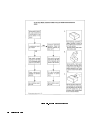
Figures
2-1. Example of a Static-Safe Workstation . . . . . .
2-2. Using Precision 7 mm Connectors . . . . . . .
2-3. SMA and 3.5 mm Connector Cross-Sections and
SWR Performance . . . . . . . . . . . . .
3-1. Detector Features . . . . . . . . . . . . . .
3-2. Typical Measurement Setup . . . . . . . . . .
4-1. Return Loss Setup . . . . . . . . . . . . . .
4-2. Frequency Response Test Setup . . . . . . . .
4-3. Frequency Response Graph . . . . . . . . . .
4-4. Dynamic Power Accuracy Test Setup . . . . . .
4-5. First Alternate Dynamic Power Accuracy Test Setup
4-6. Second Alternate Dynamic Power Accuracy Test
Setup . . . . . . . . . . . . . . . . . .
5-1. Coarse Zero/Feedthrough Nulling Adjustment . .
5-2. Coarse Zero Adjustment . . . . . . . . . . . .
5-3. Feedthrough Nulling Adjustment . . . . . . . .
6-1. Detectors and Cable Marker Kit . . . . . . . .
6-2. Module Exchange Program . . . . . . . . . .
7-1. Removing the Detector Covers . . . . . . . . .
7-2. Cable Connections . . . . . . . . . . . . . .
2-2
2-3
2-5
3-2
3-4
4-2
4-5
4-9
4-11
4-11
4-12
5-2
5-3
5-4
6-2
6-4
7-2
7-4
Tables
1-1.
1-2.
1-3.
1-4.
4-1.
4-2.
4-3.
4-4.
4-5.
4-6.
4-7.
6-1.
6-2.
6-3.
Contents-4
Agilent 85037A Standard1 . . . . . .
Agilent 85037B Specications1 . . . .
Supplemental Characteristics . . . .
Recommended Test Equipment . . . .
Return Loss Equipment Table . . . .
Frequency Response Equipment Table .
Worksheet . . . . . . . . . . . . .
Additional Equipment . . . . . . .
Test Record for 85037A . . . . . . .
Test Record for 85037A Option 001 . .
Test Record for 85037B . . . . . . .
Miscellaneous Parts . . . . . . . . .
Replaceable Parts and Accessories . .
Contacting Agilent . . . . . . . . .
.
.
.
.
.
.
.
.
.
.
.
.
.
.
.
.
.
.
.
.
.
.
.
.
.
.
.
.
.
.
.
.
.
.
.
.
.
.
.
.
.
.
.
.
.
.
.
.
.
.
.
.
.
.
.
.
.
.
.
.
.
.
.
.
.
.
.
.
.
.
1-3
1-4
1-5
1-6
4-3
4-6
4-9
4-12
4-13
4-17
4-21
6-2
6-3
6-5
1
General Information
Introduction
Product Description
This manual contains information on operating, testing, and servicing
the Agilent 85037A and 85037B precision detectors. Figure 6-1 shows
the detectors and the supplied cable marker kit.
The Agilent 85037A/B precision detectors are specically designed
for use with an Agilent 8757D scalar network analyzer and are
not compatible with the Agilent 8757A/C/E, 8756, or 8755 scalar
network analyzers. These dual0diode detectors may be used in
either AC or DC detection modes. For improved power measurement
accuracy versus frequency, each Agilent 85037 series precision
detector includes detector specic frequency response data, stored in
an internal EEPROM, which is automatically read by the 8757D.
When used in conjunction with the 8757D's internal power calibrator
(Option 002), these detectors provide the maximum absolute power
measurement accuracy.
Agilent Detector
Instruments Covered by
This Manual
Connector Type
85037A
Type-N (m)
85037A Option 001
Precision 7 mm
85037B
Precision 3.5 mm (m)
Each detector has a unique serial number. The contents of this
manual apply directly to detectors with serial numbers listed on the
title page.
General Information
1-1
Accessories
Table 6-2 lists accessories available for use with these detectors.
Equipment Required
but Not Supplied
Recommended Test
Equipment
Reflection or
Transmission
Measurements
AC Detection
Specifications and
Supplemental
Characteristics
1-2
General Information
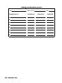
Table 1-4 lists the equipment required to test the detectors. You
may substitute any equipment that meets the indicated critical
specications.
Reection and transmission measurements require the following
equipment:
One or more detectors.
An Agilent 8757D scalar network analyzer.
One of the following:
A directional bridge.
A directional coupler.
A sweep oscillator or synthesized sweeper.
For ratio measurements use:
A power splitter or dual directional coupler.
AC detection requires the equipment listed above, plus either a signal
source capable of 27.778 kHz squarewave amplitude modulation, or
an external modulator.
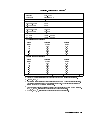
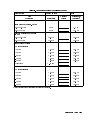
Table 1-1 and Table 1-2 list detector specications which are the
performance standards or limits against which you can test the
device.
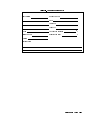
Table 1-3 lists supplemental (typical, non-warranted) detector
characteristics.
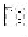
Table 1-1. Agilent 85037A Standard
1
Connector
Standard
Type-N (m)
Option 001
Precision 7 mm
Frequency Range
0.01 to 18 GHz
Return Loss
0.01 to 0.04 GHz
10 dB
0.04 to 18 GHz
20 dB
2
Frequency Response
0.01 to 0.04 GHz
60.35 dB
0.04 to 18 GHz
60.18 dB
Dynamic Range
AC mode
+20 to 055 dBm
DC mode
+20 to 050 dBm
3 ,5
DC Absolute Power Accuracy
Power
Corrected
(dBm)
(6dB)
+20
0.25
+10
0.11
030
0.11
040
0.40
050
0.85
3 ,4
AC Dynamic Power Accuracy
Default
(6dB)
0.40
0.40
0.40
0.80
1.30
Power
Corrected
Default
(dBm)
(6dB)
(6dB)
+20
0.25
0.40
+10
0.11
0.40
030
0.11
0.40
040
0.40
0.80
050
0.85
1.30
055
0.85
1.30
Temperature Coecient of Linearity
0.01 dB/ C temp. change after calibration.
1
2
3
4
5
The 85037A/B specications only apply when used with the 8757D scalar network analyzer.
010 dBm, 25 65 C
The corrected specications apply after a calibration via the 8757D Option 002 internal calibrator.
The default specications apply when the calibrator is not used. Power calibrator uncertainty is
included in the 85037A/B corrected specications.
Dynamic accuracy refers to measurement accuracy as power varies (in dB) from a 0 dBm reference.
25 65 C, 50 MHz, calibration and measurement at the same temperature.
DC mode, 25 65 C, calibration and measurement at the same temperature.
General Information
1-3
Table 1-2. Agilent 85037B Specifications
1
Connector
3.5 mm (m)
Frequency Range
0.01 to 26.5 GHz
Return Loss
0.01 to 0.04 GHz
10 dB
0.04 to 18 GHz
20 dB
18 to 26.5 GHz
18 dB
2
Frequency Response
0.01 to 0.04 GHz
60.35 dB
0.04 to 18 GHz
60.18 dB
18 to 26.5 GHz
60.22 dB
Dynamic Range
AC mode
+20 to 055 dBm
DC mode
+20 to 050 dBm
3,5
DC Absolute Power Accuracy
Power
Corrected3
(dBm)
(6dB)
+20
0.25
+10
0.11
030
0.11
040
0.40
050
0.85
3 ,4
AC Dynamic Power Accuracy
Default
(6dB)
0.40
0.40
0.40
0.80
1.30
Power
Corrected
Default
(dBm)
(6dB)
(6dB)
+20
0.25
0.40
+10
0.11
0.40
030
0.11
0.40
040
0.40
0.80
050
0.85
1.30
055
0.85
1.30
Temperature Coecient of Linearity
0.01 dB/ C temp. change after calibration.
1
2
3
4
5
1-4
The 85037A/B specications only apply when used with the 8757D scalar network analyzer.
010 dBm, 25 65 C
The corrected specications apply after a calibration via the 8757D Option 002 internal calibrator.
The default specications apply when the calibrator is not used. Power calibrator uncertainty is
included in the 85037A/B corrected specications.
Dynamic accuracy refers to measurement accuracy as power varies (in dB) from a 0 dBm reference.
25 65 C, 50 MHz, calibration and measurement at the same temperature.
DC mode, 25 6 5 C, calibration and measurement at the same temperature.
General Information
Table 1-3. Supplemental Characteristics
Cable Length
Weight
Net
Shipping
1.22m (48 in)
0.24 kg (0.5 lb)
1 kg (2.2 lb)
RF Connector Mechanical Tolerances
Type-N male (85037A)
Recession of the male center conductor
0.207 to 0.210 in1
Precision 7 mm (85037A Option 001)
Recession of the center conductor2
Collet resilience
0 to 0.003 in
After you depress the collet, it must spring back out.
Precision 3.5 mm (85037B)
Recession of the male center conductor
0 to 0.003 in
Because a type-N gage calibration block zeros the gage at a 0.207 inch oset, the gage displays a 0.207 to 0.210 inch oset as
0.000 to 0.003 inches.
2 With the center conductor collet removed.
1
General Information
1-5
Table 1-4. Recommended Test Equipment
Item
Type-N Connector Gage Kit
7 mm Connector Gage Kit
3.5 mm Connector Gage Kit
Collet Extractor Tool
Synthesized Sweeper
Scalar Network Analyzer
Directional Bridge
Power Meter
Calibrated Power Sensor
10 dB Attenuator
Calibrated Short
Shielded Open
Calibrated Short/Shielded Open
Adapter
Torque Wrench
1-6
General Information
Critical
Specications
Required for 85037A
No substitute
Required for 85037A Option 001
No substitute
Required for 85037B
No substitute
Required for 85037A Option 001
No substitute
Compatible with 8757D
No substitute
Compatible with 8757D
AC/DC detection
Type-N
Precision
Precision
Type-N
Precision
Precision
Type-N
Type-N
7 mm
3.5 mm
7 mm
3.5 mm
Precision 3.5 mm
Precision 7 mm
Type-N (f) to BNC (m)
Type-N (m) to Type-N (m)
3.5 mm (f) to 3.5 mm (f)
Type-N (m) to APC-7
(Option 001 only)
Precision 7 mm 12 in-lb
(85037A Option 001)
20 mm 8 in-lb (85037B)
Agilent Model or
Part Number
85054-80011
85050-80012
11752-60105
5060-0370
83620A/30A
8757D
85027A/B/C
436A, 437B or 438A
8481A
8481A Option 001
8485A
8491B Option 010
8492A Option 010
8493C Option 010
11511A
85032-60001
85037-60001
85021-60001
1250-1534
1250-1475
1250-1749
11525A
8710-1766
8710-1764
2
Installation
Safety
There are no hazardous voltages in this detector.
Considerations
Initial Inspection
1.
2.
3.
4.
Check the shipping container and packaging material for damage.
Check that the shipment is complete.
Check connector, cable, and detector body for mechanical damage.
Check the detector electrically:
Either make a measurement or test to specications. (See Chapter
3, \Operation" or Chapter 4, \Performance Tests.")
If any of the following conditions exist, notify your nearest Agilent
oce:
incomplete shipment
mechanical damage or defect
failed electrical test
If you nd damage or signs of stress to the shipping container or the
cushioning material, keep them for the carrier's inspection. Agilent
does not wait for a claim settlement before arranging for repair or
replacement.
Installation
2-1
Preparation for Use
Caution
Electrostatic Discharge
(ESD)
Do not subject the detector to mechanical shock.
ESD can damage the highly sensitive microcircuits in this device;
charges as low as 100 V can destroy a detector.
ESD damage occurs most often as you connect or disconnect a
device. Use this detector at a static-safe workstation and wear a
grounding strap. Never touch the input connector center contacts or
the cable contact pins.
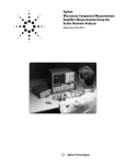
Static-Safe
Workstation
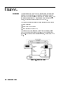
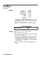
Figure 2-1 illustrates a static-safe station using two types of ESD
protection that you can use either together or separately.
A conductive table mat and wrist-strap combination.
A conductive oor mat and heel-strap combination.
Figure 2-1. Example of a Static-Safe Workstation
Static-Safe
Practices
Before cleaning, inspecting, or making a connection to a
static-sensitive device or test port, ground yourself as far as
possible from the test port.
Discharge static electricity from a device before connecting it:
Touch the device briey (through a resistor of at least 2 M
) to
either the outer shell of the test port, or another exposed ground.
This discharges static electricity and protects test equipment
circuitry.
2-2
Installation
Power Requirements
Cable Lead
Identification
Mating Connectors
Caution
Connecting an
85037A/B
The scalar network analyzer supplies power for the detector.
When you use more than one detector, use the coded cable clips
(from the cable marker kit) to identify leads; place matching clips on
each cable, one at each end.
Table 1-3 lists connector mechanical tolerances. Microwave
Connector Care (08510-90064) provides information on the proper
maintenance, inspection, and gaging of connectors. Use the
appropriate torque wrench. (See Table 1-4.)
When tightening a connector, do not apply more than the
recommended torque value. If you torque the connectors with more
pressure than is recommended it can deform the mating surfaces.
Connect a detector to the network analyzer as follows:
1. With the cable plug key downward, insert the DC connector into
the analyzer mating connector.
2. To secure the DC connector in the analyzer, turn the outer shell
clockwise.
3. For a standard detector, connect the RF input by turning the
male connector outer shell clockwise.
4. For a precision (Option 001) 7 mm connector, refer to Figure 2-2.
Figure 2-2. Using Precision 7 mm Connectors
Installation
2-3
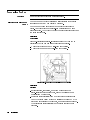
Mating a Precision 3.5 mm Connector to an SMA Connector
It is possible to mate a precision 3.5 mm connector to an SMA
connector, but this is not ideal because the two connectors have
slightly dierent dimensions and mechanical characteristics. Mating
a precision 3.5 mm connector to an SMA connector also aects the
electrical performance. (See \Electrical Performance".) Use the
following procedure to safely mate 3.5 mm and SMA connectors.
1. Inspect the SMA connector.
Never mate a precision 3.5 mm connector to an SMA connector
in which the solid plastic dielectric protrudes in front of the outer
conductor mating plane.
2. Gage both connectors. The SMA connector must meet the
precision 3.5 mm connector setback specications. If not, it will
damage the 3.5 mm connector.
In some SMA connectors, the male contact pins are not held
securely and are easily pulled out of specication (especially if
the female connector contact ngers are tight). Also, some SMA
male pins are not true pins, but are the cut-o ends of the center
conductor in semi-rigid coaxial cable. In this case, misalignment
and burrs are likely to occur.
3. Carefully align the connectors.
4. Push the two connectors together with the male contact pin
precisely concentric with the female.
5. Do not twist either connector or device.
6. Turn only the outer male connector nut.
7. Use a 60 N-cm (5 in-lb) torque wrench for the nal connection.
If you must make more than a few connections, use a 3.5 mm-to-3.5
mm adapter to protect the 3.5 mm connector.
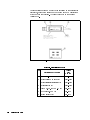
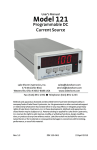
Electrical Performance. The electrical performance of the junction of
two precision 3.5 mm connectors is superior to the junction of either
two SMA connectors, or an SMA connector mated to a precision 3.5
mm connector. (See Figure 2-3.)
When you mate an SMA connector with a precision 3.5 mm
connector, the connection has a typical mismatch (SWR) of
1.10 at 2 GHz. This mismatch is less than that of two SMA
connectors, but is much higher than that of two precision 3.5 mm
connectors.
2-4
Installation
Figure 2-3. SMA and 3.5 mm Connector Cross-Sections and SWR Performance
Installation
2-5
: 0 C to +55 C.
:
Up to 95%. Protect the detector from temperature
extremes, which can cause condensation.
:
Up to 7,620m (25,000 ft).
Operating
Temperature
Environment
Humidity
Altitude
Storage and
Shipment
Environment
Store or ship the detectors in environments within the following
limits:
: 025 C to +75 C.
:
Up to 95%. Protect the detector from temperature
extremes which can cause condensation.
:
Up to 7,620m (25,000 ft).
Temperature
Humidity
Altitude
Packaging
2-6
Installation
Containers and materials identical to those used in factory-packaging
are available. Contact your local Agilent oce for information. If you
package the detector using commercially available material, follow
these instructions:
1. Wrap the detector in heavy paper.
2. Use a strong shipping container that has a double-wall carton of
at least 350-pound test material.
3. Provide a rm cushion that prevents movement inside the
container.
4. Use a 5 to 7 cm (3 to 4 inch) layer of shock-absorbing material
around all sides of the detector.
5. Seal the shipping container securely.
6. Mark the shipping container FRAGILE.
Returning a
Detector for Service
If you ship the detector to a Agilent oce or service center ll out a
blue service tag (provided at the back of this manual), and include
the following information:
1. Company name and address.
Do not use an address with a P.O. box number because products
cannot be returned to a P.O. box.
2. A technical contact person with a complete phone number.
3. The complete model and serial number of the detector.
4. The type of service required (calibration, repair).
5. Any other information, such as failure condition or cause, that
could expedite service.
When you make an inquiry, either by mail or by telephone, refer to
the detector by both model number and full serial number.
Installation
2-7
3
Operation
Operating Theory
AC Detection
DC Detection
Cautions
The 85037A/B can detect either unmodulated RF signals (DC mode)
or square wave amplitude modulated RF signals (AC mode). In
either detection mode, the detector provides a 27.778 kHz square
wave signal to the analyzer to interpret and display.
In AC detection, an RF or microwave signal is amplitude modulated
with a 27.778 kHz square wave. The detector demodulates (envelope
detects) and amplies this signal to produce a 27.778 kHz square
wave whose peak-to-peak voltage corresponds to the magnitude of
the original RF signal.
DC mode requires no modulation. The detector diode converts
the RF signal into DC voltage which is then chopped at a
27.778 kHz rate and amplied. The amplied signal is a signal
like that produced by AC detection.
Electrostatic discharge (ESD) can damage the highly sensitive
microcircuits in this device; charges as low as 100 V can destroy your
detector.
ESD damage occurs most often as you connect or disconnect a
device. Use this detector at a static-safe workstation and wear a
grounding strap. Never touch the input connector center contact, or
the cable contact pins.
Do not exceed the recommended torque specication to tighten a
connector because greater surface torque can deform the mating
surfaces.
Do not apply more than +23 dBm RF CW power or more
than 610 Vdc to the detector. Higher power/voltage can electrically
damage the detector.
Before you connect a cable to the detector, always discharge the
cable's center conductor static electricity to instrument-ground.
Do not subject the detector to mechanical shock.
Operation
3-1
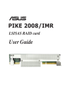
Features
Figure 3-1. Detector Features
Connector Torque
Values
3-2
Operation
Tighten the 85037A type-N connector nger-tight only.
Tighten the 85037A Option 001 with a torque wrench, part number
8710-1766 set at 13.8 cm-kg (12 in-lb).
Tighten the 85037B with a torque wrench part number 8710-1764
set at 9.2 cm-kg (8 in-lb).
Operator's Check
Operating Modes
and Specifications
Dynamic Accuracy
Frequency Response
See \Characterizing the Detector" in this chapter for a procedure
that allows you to quickly check the detector. This procedure can be
used as a daily check.
The Agilent 85037 series precision detectors have built-in corrections
for both frequency range and dynamic accuracy. These corrections
are used to enhance the measurement capability of the detector. The
following text explains how the corrections are made. Additional
information regarding detector operation is available in the 8757D
Scalar Network Analyzer Operating Manual .
The dynamic accuracy and absolute power accuracy of the detector is
measured at the factory. Approximately 150 correction constants are
then calculated and stored in the EEPROM of each detector. This
provides a default correction and is sucient to guarantee the default
dynamic accuracy specications. To obtain maximum performance,
the detector must be connected to the 50 MHz calibrator output
of the 8757D Option 002 and then characterized using the built-in
correction routine in the 8757D. Once this is done, the detector will
meet the enhanced (corrected) specication for dynamic accuracy for
both AC and DC measurements. This characterization will remain
valid until the detector is unplugged. For optimal performance
however, the detector must be recharacterized if its temperature
changes by more than 65 C.
The 85037 uses built-in correction factors to provide the best possible
frequency response. The number of correction factors will vary
with each detector, but is typically 25. These correction factors are
determined at the factory and are stored within the EEPROM of the
detector. If the 8757D is used with the system interface, then the
analyzer will automatically determine the proper correction factor to
use; no user intervention is required. If the 8757 system interface
is not being used, then the frequency related correction factors
will be determined from the start/stop labels. These labels can be
entered into the 8757 by pressing 4
5 LABELS START LABEL (or
STOP LABEL ) and then entering the start (or stop) frequency.
NNNNNNNNNNNNNNNNNNNN NNNNNNNNNNNNNNNNNNNNNNNNNNNNNNNNNNN
SYSTEM
NNNNNNNNNNNNNNNNNNNNNNNNNNNNNNNN
Operation
3-3
However, if the frequency the detector sees is dierent from what is
being swept (for example, when using a mixer or multiplier), then the
user must manually enter the correct detector frequencies as follows:
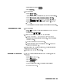
1. Press 4 5.
2. Select MORE .
3. Select DET FREQ .
CAL
NNNNNNNNNNNNNN
NNNNNNNNNNNNNNNNNNNNNNNNNN
4. Select
5. Select
6. Select
7. Select
Measurement
System
Configuration
DET A,B,C or R .
NNNNNNNNNNNNNNNNNNNNNNNNNNNNNNNNNNNNNNNNNNNN
and use the keypad to enter a value.
and use the keypad to enter a value.
NNNNNNNNNNNNNNNNNNNNNNNNNNNNNNNN
Start Freq
NNNNNNNNNNNNNNNNNNNNNNNNNNNNN
Stop Freq
DET FREQ ON .
NNNNNNNNNNNNNNNNNNNNNNNNNNNNNNNNNNN
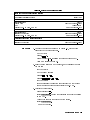
Figure 3-2 shows a typical measurement setup. AC detection mode,
the turn-on state of the 8757D analyzer, does not require any special
setup to initiate a measurement. DC detection mode, however,
requires that you press specic analyzer keys in the correct order.
Figure 3-2. Typical Measurement Setup
3-4
Operation
DC Detection
Measurements
Enabling the DC
Detection Mode
DC detection oers absolute power measurement capability and the
ability to characterize oscillators and modulation sensitive devices.
1. On the analyzer, press 4
5.
2. Connect the detector.
3. Enable DC mode:
Press 4
5 and select MODE DC .
Selecting the MODE DC softkey also turns o the source square
wave modulation.
You must enable the DC mode to access the DC-specic softkeys.
To make DC-mode measurements as shown in Figure 3-2, you
must use an 85027 directional bridge capable of both AC and DC
detection.
PRESET
NNNNNNNNNNNNNNNNNNNNNNN
SYSTEM
NNNNNNNNNNNNNNNNNNNNNNN
Remember
Making Accurate DC
Measurements
Operation
Before accurate DC measurements can be made, two quick routines
must be performed; a DC zero and a dynamic power characterization.
(This is referred to as a power calibration on the 8757 and on other
annotations.) The DC zero will improve accuracy below 035 dBm.
The dynamic characterization will provide the improved (corrected)
power accuracy specication on the 8787D Option 002 only.
Measurements can be performed without this characterization (such
as on instruments without Option 002), however only the default
dynamic accuracy specications of the detector are guaranteed. This
characterization includes a DC zero so it is not necessary to perform
the zero before performing the characterization.
Zeroing an 85037A/B
When making DC{mode measurements, you must perform a zeroing
operation to compensate for the eects of DC drift and temperature
uctuations. This is not required in AC detection. The zeroing
operation eliminates small DC voltages present in the detector that
would otherwise cause amplitude measurement errors at low power
levels (035 dBm and below). Zeroing also establishes the displayed
noise level (the system noise oor) with no RF signal applied. A
DC zero should be performed at least once every half-hour once the
system has stabilized. A DC zero should be performed more often
as the system warms up, or if the temperature is changing. The
autozero function is provided to automatically perform DC zeros
periodically when the system interface is used.
Operation
3-5
Note
Before you zero the detector, remove all RF signals from the detector
input. Even a small RF signal present during zeroing produces
measurement errors.
The 8757D analyzer has three types of zeroing:
AUTOZRO turns o the source RF signal output and
automatically zeroes the detector.
REPT AZ ON/OFF automatically repeats autozero at
selected intervals.
MANUAL is similar to power meter zeroing. First you
must either physically remove the detector from the
RF signal or turn the RF signal o, then you select
MANUAL to perform the zero.
NNNNNNNNNNNNNNNNNNNNNNN
Autozero
NNNNNNNNNNNNNNNNNNNNNNNNNNNNNNNNNNNNNNNNNNNN
Repeat
Autozero
NNNNNNNNNNNNNNNNNNNN
Manual Zero
NNNNNNNNNNNNNNNNNNNN
Note
AC Detection
Measurements
Making Accurate AC
Measurements
3-6
Operation
See the analyzer documentation for more information on these
softkeys.
AC detection is the preferred method for the majority of
measurements as it oers greater sensitivity. It also oers
immunity to noise and drift with time and temperature. AC
detection amplitude measurements require a modulation envelope.
The envelope is provided through a 27.778 kHz square wave
amplitude modulation of the RF test signal. Test set connections
vary depending on the source. Figure 3-2 illustrates a typical
measurement setup with an Agilent 8360 synthesized sweeper
supplying the 27.778 kHz modulation.
Accurate AC measurements depend heavily on the envelope of
the amplitude modulated RF signal. In addition, to obtain the
specied dynamic accuracy, a characterization of the detector (a
power cal) must rst be performed. Without this characterization,
only the default dynamic accuracy is guaranteed. Performing the
characterization will calibrate the detector in both AC and DC
modes. See \Characterizing the Detector" in this chapter.
The RF signal must be squarewave modulated at a rate within 20
Hz of 27.778 kHz. The amplitude ratio of the on portion to the
o portion of the envelope must be at least 30 dB and the ratio of
on-time to o-time should be within 5% of 50/50. Most Agilent
sources provide this capability. If your 8757D scalar network analyzer
is equipped with the Option 002 power calibrator, you can obtain the
best power measurement accuracy by following this procedure.
Characterizing the
Detector (Performing
a Power Calibration)
To obtain the best accuracy, and to meet the \corrected" dynamic
accuracy specications, each detector must be characterized on the
8757D input on which it will be used. The characterization routine
simultaneously corrects both AC and DC measurements. This
routine is also useful as an operator's check to ensure the detector
is operating properly. Only the 8757D with an Option 002 power
calibrator have this capability.
Detector characterization begins at +20 dBm and decreases in 1 dB
increments down to 035 dBm. To reduce measurement time, power
steps are larger than 1 dB at lower power levels. Correction values
will be generated over this range if the detector is operational. It
will also correct for any loss in the detector up to about 50 dB. For
example, lets assume a DC detector has a dynamic range of +20 to
050 dBm. A 30 dB attenuator is then placed on the detector and a
characterization is performed. Upon completion, the detector will be
characterized from +20 to 020 dBm. Applying a 0 dBm signal to
the detector/pad combination will result in a 0 dBm reading; not a
030 dBm reading which is what the detector itself is actually seeing.
A loss of more than about 50 dB may result in an error message
being displayed on the analyzer. This could occur if the detector is
defective or if you simply forgot to connect the detector under test to
the Power Cal Output of the 8757D.
Upon completion of this routine, the dynamic range of the detector
will be displayed; verify that it is correct for the current detection
mode, taking into account any attenuation due to added pads or
other devices, or due to inherent loss, such as in a directional bridge
which typically has 12.5 dB of loss.
To characterize the detector (perform a power cal), connect the
detector to the desired input of the 8757D. Connect the RF input of
the detector to the calibrator output. Make sure the analyzer has
been on and the detector connected for at least 30 minutes.
1. Press 4 5.
2. Select MORE .
3. Select POWER CAL .
4. Select DET A,B,C or R .
CAL
NNNNNNNNNNNNNN
NNNNNNNNNNNNNNNNNNNNNNNNNNNNN
NNNNNNNNNNNNNNNNNNNNNNNNNNNNNNNNNNNNNNNNNNNN
5. Select START CAL .
A complete characterization for one detector takes about 60 seconds.
Once characterized, do not unplug the detector from the analyzer or
you will have to perform another characterization. This is because
the 8757 automatically recalibrates itself when it senses a detector
has been removed or connected to the detector inputs. However,
the analyzer can be turned o and on again without losing this
information. Perform the characterization at least once per day and
more often if the temperature varies by more than 65 C.
NNNNNNNNNNNNNNNNNNNNNNNNNNNNN
Operation
3-7
4
Performance Tests
Use the procedures in this chapter to test the detector's electrical
performance to the specications listed in Chapter 1. None of these
tests require access to the detector's interior. To completely test each
detector, three tests are required:
1. return loss
2. dynamic accuracy (AC and DC uncorrected)
3. frequency response
Introduction
Equipment Required
Note
Preceding each test is an equipment table that lists which equipment
you will need for that particular test. You may substitute any
equipment that meets the indicated critical specications. Refer to
Table 1-4.
Before you perform a performance test, gage the input connector
on the detector and enter the results in the test record at the
end of \Performance Tests." For descriptive illustrations dening
connector tolerances, see Microwave Connector Care (part number
08510-90064).
Performance Tests
4-1
Return Loss at a
Nominal
0
10 dBm
Description
The return loss of the 85037 can be measured using the test system
described in this procedure. The test setup is calibrated using an
open/short to minimize frequency response and phasing errors. Then
the detector under test (DUT) is connected to the test port of the
bridge, and its return loss is measured on the 8757D.
The three main sources of error in these measurements come from:
1. bridge directivity
2. source match of the bridge
3. dynamic accuracy of the 8757D
The rst two vary with frequency while dynamic accuracy varies
with the measured return loss amplitude. Use the corresponding,
connector-compatible Agilent directional bridge, Agilent 85027/A/B
or C.
Figure 4-1. Return Loss Setup
4-2
Performance Tests
Table 4-1. Return Loss Equipment Table
Equipment Common to all Agilent Detectors
Scalar Network Analyzer
8360 Series Synthesized Sweeper
Additional Equipment Required for 85037A
Directional Bridge
Shielded Open
Short
Adapter Type-N (m) to 3.5 mm (f)
Additional Equipment Required for 85037A Option 001
Directional Bridge
Calibrated Open/Short
Adapter Type-N (m) to 3.5 mm (f)
Additional Equipment Required for 85037B
Directional Bridge
Calibrated Open/Short
Procedure
8757D
83620A/30A
85027C
Part Number 85032-60001
Agilent 11512A
Part Number 1250-1744
85027A
Part Number 85021-60001
Part Number 1250-1744
85027B
Part Number 85037-60001
1. Connect the equipment as shown in Figure 4-1, with nothing
connected to the bridge test port .
On the 8757D:
Press 4
5.
Press Channel 4 5 4 5 (Pressing twice turns channel 2 o).
Allow 30 minutes for warmup.
2. Reset the stop frequency on the source, and if necessary and set
the power:
For the 85037A:
On the 83620A source:
Press 4 5 4 5 4 5.
Press 4
5 40 5 4
5.
For the 85037B:
It is not necessary to reset the stop frequency on the Agilent
83630A source as it stops automatically at 26.5 GHz.
3. Calibrate the test setup.
Press Function 4 5.
Select SHORT/OPEN . Follow the directions (prompts) appearing
on the CRT.
Connect the short to the test port of the bridge.
Select STORE SHORT .
Remove the short.
PRESET
2
STOP
18
2
GHz
POWER LEVEL
3
dBm
CAL
NNNNNNNNNNNNNNNNNNNNNNNNNNNNNNNN
NNNNNNNNNNNNNNNNNNNNNNNNNNNNNNNNNNN
Performance Tests
4-3
Connect the open to the test port of the bridge.
Select STORE OPEN .
Remove the open.
The CRT will display:
SHORT/OPEN CAL SAVED IN CH1 MEM.
Press Function 4
5.
Select MEAS-MEM .
4. On the 8757D:
Connect the detector under test to the test port of the bridge.
Press Function 4
5 4 5 4 5.
Press 4
5. Use the cursor to nd the highest trace value
(the worst case measurement), in each specication range.
Write each value in the test record.
If more frequency resolution is needed at the low end of the
frequency range, repeat the preceeding procedure using a stop
frequency of 50 MHz.
NNNNNNNNNNNNNNNNNNNNNNNNNNNNNNNN
DISPLAY
NNNNNNNNNNNNNNNNNNNNNNNNNN
SCALE
5
dB
CURSOR
Note
This completes the procedure for measuring return loss.
4-4
Performance Tests
Frequency
Response at a
Nominal
0
10 dBm
Description
The frequency response of the 85037A/B detector is specied as
the maximum peak-to-peak deviation from a constant input signal
of 010 dBm, as measured over the specied frequency range.
To simplify the measurement procedure, frequency response is
measured with a nominal 010 dBm signal applied. First, the source
is characterized for frequency response using a calibrated power
meter/sensor combination. Second, the DUT is characterized.
Finally, a point-by-point dierence is computed, plotted, and
compared to the specication window. The manual test described in
this procedure has an approximate root sum of the squares (RSS)
uncertainty ranging up to 60.25 dB. This implies that a \good"
detector, well within the limits of its specications, could measure
out of specication. This measurement is only an indication of the
detector's response within these limits. If greater measurement
accuracy is desired, a test system that minimizes the sources of
measurement uncertainty will be required.
Figure 4-2. Frequency Response Test Setup
Performance Tests
4-5
Table 4-2. Frequency Response Equipment Table
Equipment Common to All Agilent Detectors
Scalar Network Analyzer
8360 Series Synthesized Sweeper
Power Meter
Additional Equipment Required for Agilent 85037A
Power Splitter
Power Meter
Calibrated Sensor
10 dB Attenuator
Crystal Detector
Additional Equipment Required for Agilent 85037A Option 001
Power Splitter
Power Meter
Calibrated Sensor
10 dB Attenuator
Crystal Detector
Additional Equipment Required for Agilent 85037B
Power Splitter
Power Meter
Calibrated Sensor
10 dB Attenuator
Crystal Detector
8757D
83620A/30A
436A/437B/438A
11667A
436A/437B/438A
8481A
8491B Option 010
8474B
11667A Opt 002
436A/437B/438A
8481A Option 001
8492A Option 010
8474A
11667B
436A/437B/438A
8485A
8493C Option 010
8473D
Procedure
Configuring the System
1. Connect the equipment as shown in Figure 4-2, with nothing
connected to the open end of the power splitter.
Turn on all equipment.
Allow 30 minutes for warmup.
2. On the power meter:
Press 4 5 mode.
Zero and calibrate the power meter. If you are unsure of how
to do this, refer to the power meter operating and service
manual.
4
5 and 4
5 should remain o.
Set the Cal Factor % on the power meter to the value
indicated for 50 MHz on the power sensor Cal Factor Chart .
3. On the 8757D:
Preset the analyzer, turn channel 2 o, and select the detector
mode for DC:
Press 4
5.
Press Channel 4 5 4 5 (Pressing twice turns Channel 2 o).
dBm
Range Hold
Power Ref
PRESET
2
4-6
Performance Tests
2
Press Instrument State 4
5.
Select MODE DC .
4. On the source:
Press 4 5 4 5 4 5.
Connect the power meter/sensor to the output of the splitter.
Press 4 5 Ext Det MORE Coupling Factor 4 5 4 5.
Press 4
5 40 5 4
5 and, if necessary, adjust the
power level for a power meter reading within 6 0.05 dB of
010 dBm.
Do not readjust the power level for the remainder of this test.
SYSTEM
NNNNNNNNNNNNNNNNNNNNNNN
CW
50
MHz
NNNNNNNNNNNNNNNNNNNNNNN NNNNNNNNNNNNNN NNNNNNNNNNNNNNNNNNNNNNNNNNNNNNNNNNNNNNNNNNNNNNN
ALC
10
POWER LEVEL
Measuring the Source
10
dB
dBm
5. On the source:
Press 4 5 and enter the test frequencies as shown on the work
sheet.
For example: 4 5 4 5 4 5.
6. Using the Cal Factor Chart on the Power Sensor:
a. Set the Cal Factor % on the power meter to the value
indicated for the test frequency as needed. (Use the nearest
frequency value.)
b. Note the reading on the power meter.
c. Record this value onto the worksheet Table 4-3 under the
\Source Power" column.
7. Repeat steps 5 and 6 using, at minimum, the test frequencies
noted on the work sheet.
8. Disconnect the power meter/sensor.
CW
CW
Measuring the Detector
.01
GHz
9. With the detector still disconnected from the source, zero the
detector:
Press 4 5 on the 8757D.
Select 4
5.
Select AUTOZERO .
When the zero is complete, the display will indicate:
AUTO ZERO COMPLETE.
CAL
DC DET ZERO
NNNNNNNNNNNNNNNNNNNNNNNNNN
Performance Tests
4-7
10. Connect the detector to the power splitter.
On the 8757D:
Press Function 4
5 to turn the cursor on.
11. On the source:
Press 4 5 and enter the rst test frequency. Remember to use
only the test frequencies used in steps 5 through 7.
12. Note and record on the worksheet (under the \Measured Power"
column) the value indicated by the 8757D cursor display.
13. Repeat this step until all of the same frequency points have been
measured.
CURSOR
CW
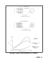
Computing the
Maximum Error
4-8
Performance Tests
14. Using the values recorded in steps 6 and 12, subtract the value
in step 6 from the value in step 12 for each of the frequencies as
shown on the worksheet.
Now use these values to plot a point to point variation curve
on the graph on the next page. The peak to peak variations
determine the frequency response of the detector. Record this
result on the test record.
This completes the procedure for measuring frequency
response.
Figure 4-3. Frequency Response Graph
Table 4-3. Worksheet
Recommended Test Frequencies
Frequency
in GHz
Measured Power
(dBm)
Source Power
(dBm)
Meas Power minus
Source Power (dB)
0.01
0.04
0.10
2
6
10
14
16
18
20
22
24
26.5
Performance Tests
4-9
Dynamic Power
Accuracy
Description
Procedure
The dynamic power accuracy of the 85037A/B is dependent upon the
raw (uncorrected) response of the detector, the correction routine
of the 8757D analyzer, and the accuracy of the 8757D Option 002
calibrator. The accuracy of the calibrator is assumed to be within
specications. This can be checked by following the performance test
procedure in the 8757D manual. The correction routine is xed and
cannot vary, so it is also assumed to be accurate. The high accuracy
of the 85037A/B is only guaranteed after performing the built-in
characterization routine (a power cal) in the 8757D. Once this is
done, performing any dynamic accuracy tests using the same 8757D
calibrator is ineectual because the only error that will be seen will
be due to measurement repeatability and any possible temperature
drift. Therefore, to verify the dynamic accuracy of the 85037A/B,
only the raw, uncorrected performance is measured. Once this has
been veried, the corrected dynamic accuracy, by design, must be
within specication. Independent verication of both corrected and
uncorrected specications can be performed by using either of the
two alternative setups shown in Figure 4-5 or Figure 4-6. Testing of
the raw dynamic accuracy performance is the only test required. The
manual test procedure follows.
1. Connect the equipment as shown in Figure 4-4. If the sweeper is
on, turn it o.
2. Allow equipment to warm up for 30 minutes.
3. Disconnect the detector.
4. Press 4
5.
5. Reconnect the detector to input A, this forces default correction.
6. Press Channel 4 5 4 5 (Pressing twice turns Channel 2 o).
7. Press 4
5.
8. Select MORE SWEEP MODE CW ON .
9. Press 4 5 MORE DET OFFSET MEASURE DET OFS DET A
45 4
5 START MEAS . Read the oset value. Note this number
as the reference value.
10. Press 4 5 PRIOR MENU 4 5 4 5 START MEAS .
11. Read the oset value shown on the 8757D and subtract from
this the reference value in step 9. Record the results on the test
record card under Dynamic Accuracy AC Mode.
12. Repeat steps 10 and 11 at the power levels shown on the test
record.
PRESET
2
2
SYSTEM
NNNNNNNNNNNNNN NNNNNNNNNNNNNNNNNNNNNNNNNNNNNNNN NNNNNNNNNNNNNNNNN
NNNNNNNNNNNNNN NNNNNNNNNNNNNNNNNNNNNNNNNNNNNNNN NNNNNNNNNNNNNNNNNNNNNNNNNNNNNNNNNNNNNNNNNNNNNNN
CAL
NNNNNNNNNNNNNNNNNNNNNNNNNNNNNNNN
0
dBm
NNNNNNNNNNNNNNNNNNNNNNNNNNNNNNNN
CAL
4-10
Performance Tests
NNNNNNNNNNNNNNNNNNNNNNNNNNNNNNNN
19
dBm
NNNNNNNNNNNNNNNNN
13. Verify the noise oor in AC mode.
Press: 4 5 AVG ON 4
5
and record the average noise oor as displayed by the cursor
reading.
14. Press 4
5 4
5 MODE DC .
15. Repeat steps 6 through 12 for DC mode. The detector should be
rezeroed between the 030 and 040 dBm steps.
NNNNNNNNNNNNNNNNNNNN
AVG
CURSOR
NNNNNNNNNNNNNNNNNNNNNNN
PRESET
SYSTEM
Figure 4-4. Dynamic Power Accuracy Test Setup
First Alternate
Dynamic Power
Accuracy
Description
Figure 4-5. First Alternate Dynamic Power Accuracy Test Setup
This setup is for performing independent verication of dynamic
accuracy in 10 dB increments up to 0 dBm in DC mode.
Performance Tests
4-11
Second Alternate
Dynamic Power
Accuracy
Description
Figure 4-6. Second Alternate Dynamic Power Accuracy Test Setup
This setup is for performing independent verication of dynamic
accuracy in 10 dB increments up to +20 dBm in DC mode.
Table 4-4. Additional Equipment
Function Generator
50 MHz Bandpass Filter
Procedure
4-12
Performance Tests
Agilent 8116A
08757-80027
1. Set the 8757D for CW, DC mode, cursor on.
2. Set the step attenuator to 20 dB.
3. Adjust the 8116 for a 50 MHz sinewave and adjust the amplitude
for a cursor reading of 0.0 dBm.
4. Adjust the step attenuator in 10 dB steps and compare the 8757D
cursor reading with the calculated applied power determined
by the calibrated step attenuator. The 20 dB step on the step
attenuator becomes the reference. The other steps are relative to
this 20 dB value.
5. The detector should be rezeroed between the 030 and 040 dBm
steps.
Table 4-5. Test Record for 85037A
Test Facility
Report Number
Date
Customer
Tested by
Model
Ambient temperature
Serial Number
Relative humidity
C
%
Options
Special Notes
Performance Tests
4-13
Table 4-5. Test Record for 85037A (2 of 3)
Model
Test Equipment Used
1.
2.
3.
4.
5.
6.
7.
8.
4-14
Performance Tests
Report Number
Model Number
Date
Trace Number
Cal Due Date
Table 4-5. Test Record for 85037A (3 of 3)
Serial Number:
Report Number:
Test
Description
Specication
Return Loss at a Nominal 010 dBm
Date:
Measured
Results
Measurement
Uncertainty1
0.01 to 0.04 GHz
10 dB
0.04 to 18 GHz
20 dB
61.0 dB
62.4 dB
60.35 dB
60.18 dB
60.18 dB
60.25 dB
60.4 dB
60.4 dB
60.4 dB
60.8 dB
61.3 dB
055 dBm
60.2 dB
60.13 dB
60.22 dB
60.30 dB
60.36 dB
60.4 dB
60.4 dB
60.4 dB
60.8 dB
61.3 dB
60.2 dB
60.13 dB
60.22 dB
60.3 dB
60.36 dB
Frequency Response at a Nominal 010 dBm
0.01 to 0.04 GHz
0.04 to 18 GHz
Dynamic Power Accuracy
AC Mode uncorrected
+19 dBm
+10 dBm
030 dBm
040 dBm
050 dBm
Noise Floor
Dynamic Power Accuracy
DC Mode uncorrected
+19 dBm
+10 dBm
030 dBm
040 dBm
050 dBm
1
Using the equipment and procedures documented in this manual.
Performance Tests
4-15
4-16
Performance Tests
Table 4-6. Test Record for 85037A Option 001
Test Facility
Report Number
Date
Customer
Tested by
Model
Ambient temperature
Serial Number
Relative humidity
C
%
Options
Special Notes
Performance Tests
4-17
Table 4-6. Test Record for 85037A Option 001 (2 of 3)
Model
Test Equipment Used
1.
2.
3.
4.
5.
6.
7.
8.
4-18
Performance Tests
Report Number
Model Number
Date
Trace Number
Cal Due Date
Table 4-6. Test Record for 85037A Option 001 (3 of 3)
Serial Number:
Report Number:
Test
Description
Specication
Return Loss at a Nominal 010 dBm
Date:
Measured
Results
Measurement
Uncertainty1
0.01 to 0.04 GHz
10 dB
0.04 to 18 GHz
20 dB
6.7 dB
61.4 dB
60.35 dB
60.18 dB
60.18 dB
60.25 dB
60.4 dB
60.4 dB
60.4 dB
60.8 dB
61.3 dB
055 dBm
60.2 dB
60.13 dB
60.22 dB
60.3 dB
60.36 dB
60.4 dB
60.4 dB
60.4 dB
60.8 dB
61.3 dB
60.2 dB
60.13 dB
60.22 dB
60.3 dB
60.36 dB
Frequency Response at a Nominal
010 dBm
0.01 to 0.04 GHz
0.04 to 18 GHz
Dynamic Power Accuracy
AC Mode uncorrected
+19 dBm
+10 dBm
030 dBm
040 dBm
050 dBm
Noise Floor
Dynamic Power Accuracy
DC Mode uncorrected
+19 dBm
+10 dBm
030 dBm
040 dBm
050 dBm
1
Using the equipment and procedures documented in this manual.
Performance Tests
4-19
4-20
Performance Tests
Table 4-7. Test Record for 85037B
Test Facility
Report Number
Date
Customer
Tested by
Model
Ambient temperature
Serial Number
Relative humidity
C
%
Options
Special Notes
Performance Tests
4-21
Table 4-7. Test Record for 85037B (2 of 3)
Model
Test Equipment Used
1.
2.
3.
4.
5.
6.
7.
8.
4-22
Performance Tests
Report Number
Model Number
Date
Trace Number
Cal Due Date
Table 4-7. Test Record for 85037B (3 of 3)
Serial Number:
Report Number:
Test
Description
Specication
Return Loss at a Nominal 010 dBm
Date:
Measured
Results
Measurement
Uncertainty1
0.01 to 0.04 GHz
10 dB
0.04 to 18 GHz
20 dB
18 GHz to 26.5 GHz
18 dB
60.7 dB
61.4 dB
62.0 dB
60.35 dB
60.18 dB
60.22 dB
60.18 dB
60.25 dB
60.3 dB
6 0.4 dB
6 0.4 dB
6 0.4 dB
6 0.8 dB
6 1.3 dB
055 dBm
60.2 dB
60.13 dB
60.22 dB
60.3 dB
60.36 dB
+10 dBm
6 0.4 dB
6 0.4 dB
0 dBm
+ 0.4 dB
030 dBm
040 dBm
050 dBm
6 0.4 dB
6 0.8 dB
6 1.3 dB
60.2 dB
60.13 dB
60.22 dB
60.22 dB
60.3 dB
60.36 dB
Frequency Response at a Nominal 010 dBm
0.01 to 0.04 GHz
0.04 to 18 GHz
18 GHz to 26.5 GHz
Dynamic Power Accuracy
AC Mode uncorrected
+19 dBm
+10 dBm
030 dBm
040 dBm
050 dBm
Noise Floor
Dynamic Power Accuracy
DC Mode uncorrected
+19 dBm
1
Using the equipment and procedures documented in this manual.
Performance Tests
4-23
5
Adjustments
Introduction
Two adjustments can be performed on the 85037A/B.
1. coarse zero adjustment
2. feedthrough nulling adjustment
Normally these two adjustments do not need to be performed. They
should only be performed if the zeroing routine fails.
Before attempting any adjustments:
Turn on all equipment and allow a minimum of 30 minutes warmup
time.
Note that the adjustments are interactive and must be performed
in the order given.
Adjustments
5-1
Coarse Zero
Adjustment
Description
The coarse zero adjustment centers the detector's DC preamp input
oset voltage within the built-in automatic zero routine's range.
This is accomplished by adjusting for the lowest overall indication of
noise on the 8757D. When the level is minimized, it indicates that
the range has been properly centered. Remove the detector's outer
covers and metal housing to allow access for making the adjustments.
(Refer to \Removing the Covers" at the beginning of Chapter 7,
\Service.")
Figure 5-1. Coarse Zero/Feedthrough Nulling Adjustment
Equipment: 8757D scalar network analyzer
Procedure
1. Connect the equipment as shown in Figure 5-1 with no input to
the detector.
2. Press 4
5.
3. Press 4
5 MORE SERVICE A4 ADC MORE CHANNEL VOLTS
CHANV LOGGER .
4. Locate the single-turn potentiometer on bottom side of the board.
While viewing the DATA READING for INPUT A, adjust the coarse
zero potentiometer (the single turn pot) for the most negative
reading (typically about 05 V). See Figure 5-2.
PRESET
NNNNNNNNNNNNNN NNNNNNNNNNNNNNNNNNNNNNN NNNNNNNNNNNNNNNNNNNN NNNNNNNNNNNNNN NNNNNNNNNNNNNNNNNNNNNNNNNNNNNNNNNNNNNNNNN
SYSTEM
NNNNNNNNNNNNNNNNNNNNNNNNNNNNNNNNNNNNNN
5-2
Adjustments
Figure 5-2. Coarse Zero Adjustment
Feedthrough Nulling
Adjustment
Description
Procedure
The feedthrough nulling is adjusted for best DC accuracy below
045 dBm. This is accomplished by adjusting for the highest
overall indication of noise on the 8757D. When the level of noise is
maximized, it indicates that the feedthrough is nulled.
Equipment: 8757D scalar network analyzer
Perform the following steps in order.
Connect the equipment as shown in Figure 5-1.
On the 8757D:
1. Press 4
5.
2. Press Channel 4 5 4 5 (Pressing twice turns Channel 2 o).
3. Press 4
5 MORE SWEEP MODE CW ON to place the 8757D in
CW mode.
4. Press 4
5 MODE DC .
5. Press 4 5 SMOOTH ON .
PRESET
2
2
NNNNNNNNNNNNNN NNNNNNNNNNNNNNNNNNNNNNNNNNNNNNNN NNNNNNNNNNNNNNNNN
SYSTEM
NNNNNNNNNNNNNNNNNNNNNNN
SYSTEM
NNNNNNNNNNNNNNNNNNNNNNNNNNNNN
SPCL
6. Press 4
5 4 5 4 5.
7. If necessary, use the arrows keys to move up or down to set the
reference line to the center of the screen. (This will be 4 divisions
up from the bottom of the CRT screen.)
8. Press 4 5 REF POSN .
9. Press 4
5 CRSR0>REF LVL .
SCALE
5
dB
NNNNNNNNNNNNNNNNNNNNNNNNNN
REF
NNNNNNNNNNNNNNNNNNNNNNNNNNNNNNNNNNNNNNNNNN
CURSOR
Adjustments
5-3
10. Press 4 5 DC DET ZERO MANUAL . The display
indicates:REMOVE RF FROM DC DETECTORS. If you have connected
the detector to an RF output, disconnect it.
11. Press CONT .
When the routine is complete the display indicates: MANUAL
ZERO COMPLETED.
12. Locate the Feedthrough Null multi-turn potentiometer which
is on the top side of the PC board, (the same side as the cable
wires). Adjust it one half turn (either direction). See Figure 5-3.
13. Repeat steps 9 through 12 until turning the Feedthrough Null
potentiometer in either direction will only decrease the displayed
noise. If the overall noise level is less (lower on the screen) than
the beginning value noted, reverse the direction of adjustment.
Continue adjusting until the noise level displayed is maximized .
NNNNNNNNNNNNNNNNNNNNNNNNNNNNNNNNNNN NNNNNNNNNNNNNNNNNNNN
CAL
NNNNNNNNNNNNNN
Figure 5-3. Feedthrough Nulling Adjustment
5-4
Adjustments
6
Replaceable Parts
Introduction
Ordering Parts
This section provides replaceable parts and ordering information.
To order a part listed in the replaceable parts Table 6-2, quote the
Agilent part number, indicate the quantity required and address the
order to your nearest Agilent oce.
Replaceable Parts
6-1
To request information on a part that is not listed in the replaceable
parts table, include the instrument model number and a description
of the part and its function. Address the inquiry to the nearest
Agilent oce.
Figure 6-1. Detectors and Cable Marker Kit
Table 6-1. Miscellaneous Parts
Item
#
6-2
Replaceable Parts
Description and Quantity
Agilent
Part
Number
1
Plastic half-body cover (2)
85025-40006
2
Label: warning max input (1)
85037-80003
Label: electrostatic sensitive (1)
85037-80002
3
Cable assembly (1)
85025-60003
4
Screw M2.5 x 0.45; 4 mm-LG (2)
0515-0972
5
Lock washer 2.5 mm (2)
2190-0583
6
Cable marker kit (1)
5061-1044
Table 6-2. Replaceable Parts and Accessories
Part
Description
Agilent Model or
Part Number
Rebuilt/Exchange Assemblies
85037A
Type-N
85037A Option 001
7 mm
85037B
3.5 mm
Accessories
Connector Gage Kits
Type-N
7 mm
3.5 mm
85037-69006
85037-69007
85037-69008
85054-80011
85050-80012
11752-60106
Collet Extractor Tool
For 85037A Option 001
5060-0370
Adapters
Type-N (f) to BNC (m)
Type-N (m) to Type-N (m)
3.5 mm (f) to 3.5 mm (f)
Type-N (m) to APC-7
(Option 001 only)
APC-3.5 (f) to N (m)
1250-1534
1250-1475
1250-1749
11525A
7.6 meter (25 foot)
61 meter (200 foot)
11679A
11679B
Extension Cables
Connector Care Manual
1250-1744
08510-90064
Replaceable Parts
6-3
Figure 6-2. Module Exchange Program
6-4
Replaceable Parts
By internet, phone, or fax, get assistance with all your test &
measurement needs.
Table 6-3. Contacting Agilent
Online Assistance: www.agilent.com/find/assist
United States
(tel) 1 800 452 4844
Japan
New Zealand
(tel) (81) 426 56 7832 (tel) 0 800 738 378
(fax) (81) 426 56 7840 (fax) 64 4 495 8950
Canada
(tel) 1 877 894 4414
(fax) (905) 206 4120
Latin America
(tel) (305) 269 7500
(fax) (305) 269 7599
Asia Pacic
(tel) (852) 3197 7777
(fax) (852) 2506 9284
Europe
Australia
(tel) (31 20) 547 2323 (tel) 1 800 629 485
(fax) (31 20) 547 2390 (fax) (61 3) 9210 5947
Replaceable Parts
6-5
7
Service
Caution
Error Messages
This product is susceptible to damage from electrostatic discharge
(ESD). When you perform any of the following procedures, wear a
grounded static-strap and work at a static-safe workstation.
The message EEPROM read failed -- A (B,C or R) Indicates that
the EEPROM calibration constants are either corrupted or unable
to be read from the detector. The problem could be in either the
detector or the 8757D. Try another detector to isolate the cause.
If the detector appears to be the cause of the problem, then the
detector needs to have the calibration constants regenerated at the
factory. Refer to \Returning a Detector for Service" in Chapter 2,
\Installation."
These detectors have only one repairable item:
The cable assembly.
If the detector fails electrically, order an exchange detector:
1. See the Replaceable parts, Table 6-2, for the part number that
matches the model that you are replacing:
85037A
85037A Option 001 or
85037B.
2. Follow \The Module Exchange Program" instructions in
Figure 6-2.
Repair
Remember
To receive exchange credit, you must return the failed assembly to
Agilent in the exchange assembly box.
Service
7-1
Repair
Replacing the Detector
Removing the Covers
1. Remove the plastic covers from the existing detector. (See
\Removing the Covers.")
2. Install the covers on the replacement detector.
3. Perform an operator's check. (See \Operator's Check" in
Chapter 3.)
4. If the replacement is a restored exchange detector, return the
defective detector using the packing material supplied.
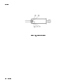
1. Place the detector with its narrow side on a at surface, with the
RF connector facing away from you. (See Figure 7-1.)
2. Holding the sides of the detector near the cable end, insert a small
at-blade screwdriver with a blade no greater than 3.5 mm (1/8
in) between the side label and the raised edge. (See Figure 7-1.)
Make sure you insert the screwdriver as far forward on the
detector as possible.
3. Rotate the screwdriver approximately 90, until the cover snaps
apart.
4. Repeat steps 2 and 3, inserting the screwdriver approximately 2/3
of the way toward the cable end of the detector. (See the point
shown in Figure 7-1.)
5. Separate the plastic shell halves. If the cover does not separate
easily, repeat steps 2 through 4 on the other side of the detector.
(See Figure 7-1.)
6. To attach the covers to a replacement detector, snap the halves
together.
Figure 7-1. Removing the Detector Covers
7-2
Service
Repair
Replacing the Cable
Assembly (W1)
Caution
1. Remove the plastic covers from the detector. (See \Removing the
Covers.")
2. Remove the two screws at the cable end of the metal housing.
3. Slide the metal housing away from the RF connector, completely
exposing the printed circuit (PC) assembly.
4. Unsolder all cable wires from the PC assembly.
5. With the PC assembly facing up, carefully secure the detector
frame in a vice. Do not grip the PC assembly.
Do not over-tighten the vice; you can bend the frame.
6.
7.
8.
9.
10.
11.
12.
13.
14.
Using a 7/16 inch open-ended wrench, unscrew the cable hex nut.
Remove the old cable assembly.
Remove the metal housing from the cable.
Carefully slide the metal housing onto the new cable
assembly, making sure that you do not cover the adjustment
potentiometers.
Solder the new cable wires to the PC assembly. (Refer to Figure
7-2.)
Ensure that all cable wires are securely connected to the
assembly.
Slide the metal housing over the PC assembly.
Using the screws removed in step 2, secure the metal housing to
the frame.
Snap the covers back on.
Service
7-3
Repair
Figure 7-2. Cable Connections
7-4
Service
A
Caring for Connectors
This appendix provides a brief introduction to the fundamentals of
proper connector care, as important to good measurements as proper
instrument calibration and adjustment. This appendix is intended to
provide basic information and tell you where to nd more: Agilent's
Microwave Connector Care . (See Table 6-2 for ordering information.)
Remember
A damaged connector can destroy any connector attached to it.
Basic connector care comprises three parts:
1. visual inspection
2. cleaning
3. mechanical inspection
Visual Inspection
Cleaning
Visually inspect all system connectors often. Examine connectors
for problems such as contamination or corrosion, especially on the
contacting surfaces. Look for deformed threads, burrs, scratches,
rounded shoulders, and similar signs of wear or damage. Any visible
problem can degrade performance; clean, reinspect, and, if necessary,
replace the connector.
Try compressed air rst.
Use compressed air to loosen particles on the connector mating
plane surfaces. Clean air cannot damage a connector, or leave
particles or residues behind.
If a solvent is necessary, use only isopropyl alcohol.
If there is dirt or contamination on a connector that you cannot
removed with compressed air, try a foam swab or lint-free cleaning
cloth moistened with isopropyl alcohol.
Use the least amount of alcohol possible.
Avoid getting any plastic parts in the connectors wet with the
alcohol.
Never spray alcohol directly into a connector.
Check the alcohol periodically for contamination.
Caring for Connectors
A-1
Mechanical Inspection
A-2
Caring for Connectors
Because coaxial connector mechanical tolerances can be very precise
(on the order of a few hundredths of microinches), even a perfectly
clean, unused connector can cause trouble if it is mechanically out of
specication. Use a connector gage to mechanically inspect coaxial
connectors. Gage a connector at the following times:
Before you use it for the rst time.
If either visual inspection or electrical performance indicates that
the connector interface may be out of specication (due to wear or
damage, for example).
The device is used on another system or piece of equipment.
As a matter of routine: initially after every 100 connections, and
after that as often as experience suggests.
Index
A
B
C
D
AC detection, 1-2, 3-1
adjustments, 5-1
coarse zero adjustment, 5-1{2
feedthrough nulling adjustment, 5-1{2
autozero, 4-7
bridge
directivity, 4-2
source match, 4-2
cable
lead identication, 2-3
replacing, 7-3
cable assembly, 7-3
characterizing the detector, 3-7
characterizing the source, 4-7
cleaning connectors, A-1
coarse zero adjustment, 5-1
computing the maximum error, 4-8
worksheet, 4-9
connector
care, A-1
cleaning, A-1
mating, 2-3
mating a 3.5 mm to an SMA connector, 2-4
mechanical inspection, A-2
torque values, 3-2
visual inspection, A-1
contacting Agilent, 6-5
cover
attaching, 7-2
removing, 7-2
DC detection, 3-1
detector
characterization, 3-7
connecting, 2-3
power calibration, 3-7
replacing, 7-2
zeroing, 3-5
detector rebuild/exchange, 7-1
dynamic accuracy, 3-3
dynamic accuracy of the 8757D, 4-2
dynamic power accuracy, 4-10
Index-1
E
F
feedthrough nulling adjustment, 5-1
oor mat
use, 2-2
frequency response, 4-5
correction constants, 3-3
correction factors, 3-3
G
gaging, 2-4
H
heel strap
use, 2-2
I
M
O
P
Index-2
electrical performance, 4-1
electrostatic discharge (ESD), 2-2
cautions, 3-1
equipment, 4-6
exchange credit, 7-1
initial inspection, 2-1
installation, 2-1
mat
use, 2-2
measurement errors
sources, 4-2
measurements
AC detection, 3-6
DC detection, 3-5
measurement system conguration, 3-4
measuring the detector, 4-7
measuring the source, 4-7
mixer or multiplier, when using
manually entering frequencies, 3-3
module exchange program, 6-4
operating environment, 2-6
operation
theory, 3-1
ordering parts, 6-1
packaging, 2-6
performance tests, 4-1
dynamic accuracy, 4-1{10
frequency response, 4-1, 4-5
return loss, 4-3
power
requirements, 2-3
R
S
T
W
Z
reection measurements, 1-2
removing covers, 7-2
repairable parts, 7-1
replaceable parts, 6-1
replacing
cable, 7-3
detector, 7-2
return loss, 4-3
test description, 4-2
safety considerations, 2-1
service, 7-1
returning detector for service, 2-7
setup
AC detection mode, 3-4{6
DC detection mode, 3-4{5
static-safe
practices, 2-2
workstation, 2-2
storage and shipment, 2-6
environment, 2-6
table mat
use, 2-2
test records, 4-13
transmission measurements, 1-2
W1 cable
replacement, 7-3
wrist strap
use, 2-2
zeroing, 3-6
autozero, 3-6
manual zero, 3-6
repeat zero, 3-6
Index-3